Embed Size (px)
Citation preview

Detection and Modelling of Nonlinear Elastic Response in
Damaged Composite Structures
F. Ciampa1, E. Onder1, E. Barbieri2, M. Meo1*
1Material Research Centre, Department of Mechanical Engineering, University of Bath,
Bath, BA2 7AY, UK
2The School of Engineering and Material Science, Queen Mary, University of London,
Mile End Road, London, E1 4NS, UK
*Corresponding author: [email protected]
Abstract
In this paper the nonlinear material response of damaged composite structures under
periodic excitation is experimentally and numerically investigated. In particular, the
nonlinear wave propagation problem was numerically analysed through a finite element
model able to predict the nonlinear interaction of acoustic/ultrasonic waves with
damage precursors and micro-cracks. Such a constitutive model is based on the
Landau’s semi-analytical approach to account for anharmonic effects of the medium,
and is able to provide an understanding of nonlinear elastic phenomena such as the
second harmonic generation. Moreover, Kelvin tensorial formulation was used to extend
the wave propagation problem in orthotropic materials to the 3D Cartesian space. In this
manner, the interaction of the stress waves with the 3D crack could be analysed. This
numerical model was then experimentally validated on a composite plate undergone to
impact loading. Good agreement between the experimental and numerical second

harmonic response was found, showing that this material model can be used as a simple
and useful tool for future structural diagnostic applications.
Keywords: Nondestructive Evaluation Techniques, Nonlinear Ultrasound, Finite
Element Method, Multiscale Modelling.
1 Introduction
Composite materials are renowned for their high strength to weight ratio,
resistance to fatigue and low thermal expansion. However, due to their fragility to
foreign object impacts, they present challenges for damage detection as much of the
flaw is often interlaminar and not readily detectable. Such a defect is commonly referred
to barely visible impact damage (BVID) and, if not promptly identified, it may cause
strength and stiffness reductions driving the structure to collapse.
In the last few decades, a number of acoustic/ultrasonic-based Non-destructive
(NDT) Evaluation techniques and Structural Health Monitoring (SHM) systems were
developed to provide an early detection and warning of critical defects [1], [2]. Most of
them analyse the variations of linear properties of the elastic waves propagating into the
medium due to the presence of damage. Indeed, changes of the wave speed and
amplitude can be used as a signature to access the location and severity of structural
anomalies. However, acoustic/ultrasonic methods based on classical linear
elastodynamic theory can be difficult to apply to inhomogeneous materials, such as
composite laminates, and, in general, to damaged structures where the crack size is
comparable with the wavelength (e.g. micro-cracks, delamination, inclusions, etc…)
[3].
Recent studies have shown that nonlinear ultrasonic measurements are sensitive
to low levels of defects and they can be used for detecting damages at their earliest
stages [4], [5]. In particular, it was analytically and experimentally shown that the
progressive degradation of the material structure and the presence of cracks create
ultrasonic wave distortion along the wave propagation path. From a physical point of
view, when a damage specimen is excited by an external dynamic load, the excitation
produces compressive and tensile stresses on the edges of the crack, causing its
“clapping” motion [6]. Hence, due to mechanical contacts between the crack interfaces,
the wave induced response of the material generates nonlinear elastic effects such as
higher harmonics of the excitation frequency [7].
Therefore, nonlinear elastic wave spectroscopy (NEWS) and phase symmetry
analysis (PSA) techniques were developed to provide an effective means to characterise
the structural damage by investigating the magnitude of higher (even) harmonics caused
by nonlinear material behaviour [8], [9]. Particularly, as the second harmonic is
quadratic with the amplitude of the fundamental frequency, it can be used as a signature
of the presence of cracks or delamination within the medium [10]. Simplified nonlinear
elastic theories have attempted to significantly provide an understanding of the
generation of nonlinear phenomena in metallic and composite structures, especially in
the presence of micro-cracks [11], [12], [13], [14]. However, these analytical
approaches are mainly 1D or 2D and they may not succeed in reproducing the whole set
of observed phenomena. Hence, numerical models can be used as an alternative for a
more complete analysis, including the extension to the 3D space for anisotropic
structures [15], [16], [17], [18].
The aim of this paper is to experimentally and numerically investigate nonlinear
material responses of damaged composite structures. In particular, the nonlinear wave
propagation problem was numerically analysed through a nonlinear elastic material
model for the simulation of the acoustic/ultrasound stress waves with micro-cracks.
Such a constitutive model is implemented in an explicit in-house finite element (FE)
numerical software and it is based on the Landau’s semi-analytical approach to account
for anharmonic effects of the medium. In particular, the nonlinear structural response of
the damaged material under continuous periodic (harmonic) input is represented through
a finite number of FE elements with varying properties defining their nonlinear stress-
strain relationship. Moreover, Kelvin tensorial formulation was used to extend the wave
propagation problem in orthotropic materials to the 3D Cartesian space. In this manner,
the interaction of the stress waves with the 3D crack could be analysed. As a result, it
was possible to numerically reproduce nonlinear experimentally-observed phenomena
such as the even (second) harmonic generation effect. This numerical model was then
experimentally validated on a composite plate undergone to impact loading. Good
agreement between the experimental and numerical second harmonic response was
found, showing that this material model is able to provide an understanding of nonlinear
elastic phenomena in composite structures with different levels of damages.
The layout of the paper is as follows: in Section 2 the 3D nonlinear elastic model for
composite structures is presented. Section 3 reports the numerical test case used for the
comparison with experimental test, whilst Section 4 illustrates the experimental set-up
and the NDT techniques (C-scan and CT-scan) used to detect and access the damaged
area. The comparison between the numerical and experimental results is presented in
Section 5 and then, the conclusions of the paper are discussed.

2 Nonlinear Constitutive Model
Linear stress-strain relationship defined in Hooke’s law is usually inadequate to
describe the nonlinear mechanical behaviour of solids with distributed damage (micro-
cracks and micro voids) and with inelastic behaviour [19], [20]. Indeed, damaged
materials such as aluminium, steel and composites that have atomic elasticity arising
from atomic-level forces between atoms and molecules, exhibit classical nonlinear (also
known as anharmonic) effects which can be described by the nonlinear elastic theory of
Landau [21]. Particularly, the expression of the nonlinear elastic modulus KC can be
obtained through a 1D power law expansion of the stress with respect to the strain :
2
0 1 KKC (1)
where K0 is the linear elastic modulus, and are classical second order and third order
nonlinear coefficients. However, for most of solids only the first nonlinear term can
be sufficient to predict the material’s nonlinear response. This coefficient can be
experimentally obtained from the measurement of the second harmonic amplitude
generated from a single pure tone input [22]. Moreover, since Eq. (1) represents a scalar
model, it cannot be used to investigate the 3D anisotropic material behaviour of a
cracked sample to different types of waves (bulk waves, guided waves, etc…) (Fig. 1).
Figure 1 Material nonlinear response with a 3D crack.

Hence, to overcome this limitation, Kelvin notation was used to extend the standard
Voigt stress-strain formulation in a tensorial equivalent form for the 3D Cartesian space
[23]. Indeed, by introducing Kelvin representation, the Voigt stress-strain relationship
for a homogeneous orthotropic elastic medium becomes:
εKσ ~~~ (2)
where the new components of the 6D stress and strain vectors are:
T
T
231312332211
231312332211
2,2,2,,,~
2,2,2,,,~
ε
σ (3)
and K~
is the new six by six stiffness matrix defined by:
TKTK ~
with
I
IT
20
0 (4)
where K is the stiffness matrix in Voigt formulation. The symmetric matrix K~
can be
shown to represent the components of a second-rank tensor in the 6D space [24]. In
accordance with Ciampa and Meo [25], the aim of this approach consists of determining
the eigenmoduli and the associated eigentensors ε~ of Eq. (2) in order to form an
ortho-normalized basis for the stress and strain tensors of the second rank. In this
manner, these tensors can be decomposed with respect to this basis in the 6D space. In
other words, we seek for the eigenvalues (known as Kelvin moduli) that satisfy the
following equation:
0~~ εΛIK . (5)
Since the six-dimensional linear transformation K~
is assumed to be symmetric and
positive definite, there will be a maximum of six positive eigenelastic constants i
( 6,,1i ) associated to Eq. (5). In addition to the six values of Λ , also six values of

ε~ will be associated to the problem (5), which are denoted by the vector iε~ in the 6D
space. The stresses iσ~ obtained by multiplying i
ε~ by the eigenvalues i are called
the stress eigentensors. Therefore, a Cartesian basis in the 6D space can be constructed
from the normalized strain eigentensors, denoted by N~
:
1~~
;~~~;~~~ 2 NNεεεεNε . (6)
Hence, the stress eigentensors can be written in terms of the normalized strain
eigentensors using Eqs. (2), (5) and (6) as:
ii
iεσ ~~ . (7)
With respect to the 6D space, σ~ , ε~ and K~
have the following representation:
6
1
6
1
6
1
6
1
~~~~
~~~~
i
ii
i
i
i
ii
i
i
i
i
Nεεε
Nεεσ
(8)
and:
i
i
i
i NNK~~~ 6
1
(9)
where indicated the tensor or dyadic product. The projection of the strain state given
by Eq. (3) along the eigenvectors obtained using Eq. (8) defines the eigenstrain vector
i~ . Thereby, the total elastic modulus due to nonlinear material behaviour defined in
Eq. (1) becomes:
2
,~~1
~iiiiTOTK . (10)
Once the total elastic modulus iTOTK ,
~ ( 6,,1i ) is obtained, according to Eqs. (10)
and (9), the 6 x 6 nonlinear stiffness matrix KTOT can be then transformed from Kelvin

to Voigt notation and it can be used for the implementation of the explicit FE numerical
method at each individual time step.
2.1 Nonlinear Finite Element Simulation
The application of explicit FE analysis in wave propagation problems allows computing
the nodal forces and displacements without recourse to a factorization of the global
stiffness matrix in a step-by-step solution. Let us consider a 3D solid domain with
boundary discretized with 3D elements. The weak form of the equilibrium equations
for the continuum can be derived from the displacement variational principle as
follows [26]:
intFFuM ext (11)
where the dots superscript denotes a second time derivative operation of the global
displacement vector u and the external nodal forces vector extF , the internal nodal
forces vector intF and the (lumped) diagonal mass matrix M are:
eln
e
eeTe
1
int uLCLF (12a)
el
ee
n
e
TTTeext dd1
bΦtΦLF (12b)
eln
e
eeTe
1
LmLM (12c)
where eL is the Boolean connectivity matrix that gather the nodal displacement e
d of
each element e to the global one over the entire domain , eln is the total number of
elements, e and e are the element domain and its boundary, TΦ is the transpose of
the shape function matrix, t and b are the surface traction and body (inertial) force of
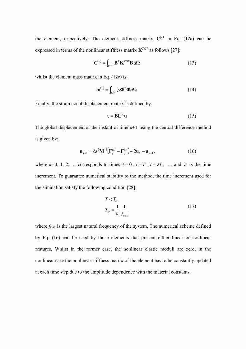
the element, respectively. The element stiffness matrix eC in Eq. (12a) can be
expressed in terms of the nonlinear stiffness matrix KTOT as follows [27]:
e
dTOTTeBKBC (13)
whilst the element mass matrix in Eq. (12c) is:
e
dTeΦΦm . (14)
Finally, the strain nodal displacement matrix is defined by:
uBLε
e (15)
The global displacement at the instant of time k+1 using the central difference method
is given by:
1
int12
1 2
kk
ext
k kkt uuFFMu . (16)
where k=0, 1, 2, … corresponds to times 0t , Tt , Tt 2 , …, and T is the time
increment. To guarantee numerical stability to the method, the time increment used for
the simulation satisfy the following condition [28]:
max
11
fT
TT
cr
cr
(17)
where fmax is the largest natural frequency of the system. The numerical scheme defined
by Eq. (16) can be used by those elements that present either linear or nonlinear
features. Whilst in the former case, the nonlinear elastic moduli are zero, in the
nonlinear case the nonlinear stiffness matrix of the element has to be constantly updated
at each time step due to the amplitude dependence with the material constants.

3 Numerical Test Case
The influence of nonlinear material effects on the FE model illustrated above was first
numerically verified on a 3D composite plate with dimensions 153 x 106 x 3 mm (Fig.
2).
Figure 2 Geometry of the 3D composite plate.
The mesh was made of 15000 nodes with 77322 nodes in way that the element
length was approximately 1 mm. The mechanical properties are reported in Table 1,
whilst the stacking sequence for a quasi-isotropic laminate is [0/45/90/-45]s.
Table 1: Orthotropic Material Properties
E11
(GPa)
E22
(GPa)
E33
(GPa)
G12
(GPa)
G23
(GPa)
G31
(GPa)
12 23 31
kg/m3
131 9 9 5.7 5.37 5.37 0.3 0.29 0/34 1545
The numerical model was meshed with tetrahedral solid elements using the
isoparametric formulation and it was implemented in an in-house FE code developed by
the authors. According to Fig. 2, the plate was modelled in a cantilever position so that
it was fixed at one end, whilst the other was kept free. The plate was dynamically

loaded with a continuous, harmonic and uniform in-plane traction force according to the
following periodic law:
)2sin( 0tfAts (18)
where A is the amplitude of the input source and f0 is the excitation frequency. In this
case, an amplitude A=5x10³ Pa and a fundamental frequency f0=150 kHz were used.
Such a time-dependent pressure distribution was applied from an area located at xi=90
mm and yi=48 mm on the top surface, in way to represent the numerical model of two
sensors operating in pitch-catch mode. The output (in-plane displacement) of the
numerical model was measured within a time window of 3105 s and, according to
Eq. (17), the sampling time (time step) was set to 7101 T s.
4 Experimental set-up
The experiments were carried out on a composite CFRP plate with the same
dimensions and a lay-up sequence as in the numerical case (Fig. 3).
Figure 3 Experimental set-up.
A dropped-weight impact test machine with a hemispherical tip was used for hitting the
test panel at 12 J. Such an energy level was chosen in order to inflict damage in the
composite laminate corresponding to a BVID. In order to transmit the input source and

measure the material nonlinear response, two different surface bonded transducers were
used, i.e. a broadband APC sensor with diameter of 6.35 mm and thickness of 2.55 mm,
and a MFC-P2 transducer with length of 37 mm and width of 18 mm. The APC sensor
was employed as receiver and it was instrumented with an oscilloscope (Picoscope
4224) with a sampling rate of 10 MHz and an acquisition window of 3105 s. To
transmit the continuous sinusoidal waveform with a frequency f0=150 kHz, the MFC
transducer was linked to a preamplifier and connected to an arbitrarily waveform
generator (TTi-TGA12104). Additionally, the carbon fibre specimen was positioned on
two foam pieces in order to reduce the environmental noise (Fig. 4).
Figure 4 Set-up of the data acquisition system.
4.1 Evaluation of Damaged Area
In order to obtain a qualitative image of the delamination generated by the impact and,
thus, to provide an indication of the damaged area, two standard NDT tests were
performed, i.e. an ultrasonic C-Scan and an X-ray tomography (CT-Scan). In the first
test, the “USL SCM 12X” ultrasonic C-Scan was used to image the defect (Fig. 5).
Indeed, this linear ultrasonic test showed two damage locations with an “apparent”
undamaged area in the middle of the composite specimen (represented by a white colour

area). However, since a protrusion occurred as a result of impact loading, the ultrasonic
C-scan was able to reveal only the presence of damage within the laminate, but it was
not able to detect and access the damaged area beneath this protrusion due to poor
acoustic impedance.
Figure 5 Image of the defect using ultrasonic C-Scan.
Therefore, in way to obtain a quantitative estimation of the presence of delamination
beneath the composite surface, a second nondestructive test was performed. In
particular, a “Nikon Metrology XT H 225 ST” computational tomography machine was
used to take a series of 2D X-ray images of the test specimen. Fig. 6 displays the
damaged area at various depths caused by the impact within the cross-section of the
material.
Figure 6 CT-scan image showing the damages occurred at a different depth.

Since at the impact point loaded laminates were pushed upwards causing all the
laminates to move towards the top of the specimen, an indentation on the bottom and a
protrusion on the top of the sample were generated. This resulted in the creation of a
“pine tree” shape of the damage with three different delaminations occurred within the
composite laminate (Fig. 6). Therefore, based on the CT-scan results, for the calculation
of the damaged location a circular area was assumed with a radius of 10 mm and a
thickness of 2 mm.
5 Numerical and Experimental Results
According to the previous section, the nonlinear classical material was modelled by
imposing a combination of the semi-analytical Landau and Kelvin formulation to those
elements within the damaged area. In this manner, the 3D nonlinear response to
different types of stress waves could be simulated. In order to compare the amplitude of
the second harmonic between the numerical model and the experimental test, only the
influence of the second order nonlinear coefficient was considered [Eq. (10)].
Moreover, the mesoscopic elements with nonlinear features were assumed to be
uniformly distributed over a circular area with diameter of 20 mm and thickness of 2
mm located at the middle of the plate.
The quadratic nonlinear parameter was experimentally calculated as the ratio between
the amplitude of the second harmonic and the square value of the fundamental one, and
it was used as an input for simulating the nonlinear behaviour of the composite
structure. In our case a value of =0.4 was found. Hence, the nonlinear signature
(harmonic generation) could be easily disclosed by the analysis the recorded signals in
the frequency domain. Fig. 7 shows the comparison of the fast Fourier transformation

(FFT) of the in-plane displacement component ux at xi=30 mm and yi=50 mm from both
the experimental and numerical (FE) tests.
Figure 7 Comparison of the in-plane displacement spectra from experimental (red) and simulated (blue)
material responses.
From Fig. 7 it can be clearly seen that a good agreement between the values of the
second harmonic from the experimental and numerical tests was achieved. Indeed, in
accordance with theoretical and experimental evidence [29], [30], [31], the second
harmonic contribution is predominant in the measured material response due to the
presence of damage. Moreover, it should be noted that the amplitude of the fundamental
harmonic was normalized to a unit value. In this manner, it was possible to compare
both simulated and experimental material responses in the case where no information
about the mechanical pressure exerted by the actuator sensor was provided.
Hence, this numerical model can be employed to understand the nonlinear behaviour of
3D composite structure, or, alternatively, for nonlinear inverse problems, in which the
size of the micro-crack or the fatigue crack grow can be estimated from the analysis of
the harmonic structural responses.

Conclusions
The purpose of this study was to validate a numerical elastic material model with
experimental results for the analysis of the nonlinear harmonic response in composite
structures. By means of semi-analytical Landau and Kelvin formulation, this
constitutive model allows the description of the structural response under continuous
harmonic excitation in 3D composite laminates. In this manner, nonlinear elastic effects
observed experimentally such as the second harmonic generation could be simulated. To
validate the proposed model, experimental tests were conducted on a composite plate
undergone to impact loading. Good agreement in the level magnitude of the second
harmonic between the numerical and experimental tests, not only verify the validity of
the theoretical model, but also shows its promising future in the application of
nondestructive testing. Future work is now undergoing to extend this model to further
nonlinear elastic phenomena such as vibro and inter-modulation (side-bands generation)
in a variety of materials.
References
[1] J.-B Inh, F.-K Chang. Pitch-catch active sensing method in structural health
monitoring for aircraft structures. Struct Health Monit 7(1), 5-19 (2008).
[2] V. Giurgiutiu, A. Zagrai, J.-J. Bao. Piezoelectric waver embedded active sensors for
aging aircraft structural health monitoring. Struct Health Monit 1(1), 41-61 (2002).
[3] W. J.-N. de Lima and M.-F. Hamilton, “Finite-amplitude waves in isotropic elastic
plates”, J. Sound Vib. 265, 819 (2003).

[4] K. E.-A. Van Den Abeele, K. Van de Velde, J. Carmeliet. “Inferring the degradation
of pultruded composites from dynamic nonlinear resonance measurements”, Polym.
Compos. 22, 555-567, (2001).
[5] P.-B. Nagy, L. Adler. “Acoustic Nonlinearity in plastics”, in Review of Progress in
Quantitative Nondestructive Evaluation, edited by D. O. Thompson and D. E.
Chimenti (Plenum, New York, 1992), Vol. I IB, 2025-2032, (1992).
[6] C. Pecorari. “Nonlinear interaction of plane ultrasonic waves with an interface
between rough surfaces in contact”. J. Acoust. Soc. Am. 113 (6), 3065-72 (2003).
[7] J.H.-Cantrell. “Fundamentals and applications of non-linear ultrasonic non-
destructive evaluation”. In: Kundu Tribikiram, editor. Ultrasonic non-destructive
evaluation, vol. 6. Boca Raton (FL): CRC Press; 363-434 (2004)
[8] K. E.-A. Van Den Abeele, P.-A. Johnston, A. Sutin. “Nonlinear elastic wave
spectroscopy (NEWS) techniques to discern material damage, part I: nonlinear wave
modulation spectroscopy (NWMS)”. Res. Nondestr. Eval. 12 (1), 17-30 (2000).
[9] F. Ciampa, M. Meo. “Nonlinear elastic imaging using reciprocal time reversal and
third order symmetry analysis”. J. Acoust. Soc. Am. 131 (6), pp. 4316-23 (2012)
[10] V.-V. Kazakov, A. Sutin, and P.-A. Johnson. “Sensitive imaging of an elastic
nonlinear wave-scattering source in a solid”, Appl. Phys. Lett. 81, 646–648 (2002)
[11] O. Bou Matar, P.-Y Guerder, Y. Li, B. Vandewoestyne, K. E.-A. Van Den
Abeele. “A nodal discontinuous Galerkin finite element method for nonlinear elastic
wave propagation”. J. Acoust. Soc. Am. 131 (5), pp. 3650-63 (2012)
[12] S. Hirose, J.-D. Achenback, “Higher harmonics in the far field due to dynamic
crack-face contacting”, J. Acoust. Soc. Am., 93 (1), pp. 142–147 (1993)
[13] P. Delsanto, M. Scalerandi, “A spring model for the simulation of the
propagation of ultrasonic pulses through imperfect contact interfaces”, J. Acoust.
Soc. Am., 104, 2584 (1998)
[14] M. Scalerandi, V. Agostini, P.-P Delsanto, K. E.-A. Van Den Abeele, P.-A.
Johnson. “Local interaction simulation approach to modelling nonclassical, nonlinear
elastic behaviour in solids”. J. Acoust. Soc. Am. 113 (6), (2003).
[15] K. E.-A. Van Den Abeele, F. Shubert, V. Aleshin, F. Windels. J. Carmeliet.
“Resonnat bar simulations in media with localized damage”, Ultrasonics 42 (1-9),
1017-1024 (2004).
[16] S. Vanaverbeke, K. E.-A. Van Den Abeele. “Two-dimensional modelling of
wave propagation in materials with hysteretic nonlinearity”, J. Acoust. Soc. Am.,
122, pp. 58–72 (2007).
[17] G. Zumpano, M. Meo. “A new nonlinear elastic time reversal acoustic method
for the identification and localisation of stress corrosion cracking in welded plate-
like structures – A simulation study”. Int. J. Solids Struct. 44, 3666–84 (2007).
[18] E. Barbieri, M. Meo. “Time reversal DORT method applied to nonlinear elastic
wave scattering”. Wave Motion 47 (7), 452–467 (2010).
[19] L. Ostrovsky, P.-A. Johnson. “Dynamic nonlinear elasticity in geomaterials”.
Riv. Nuovo Cim. 24, 1−46 (2001).
[20] P.-A. Johnson. The Universality of Nonclassical Nonlinearity (with application
to Nondestructive Evaluation and Ultrasonics), Chap. 4, Springer New York, 49–69,
(2006).
[21] L.-D. Landau, E.-M. Lifshitz, Theory of Elasticity, Pergamon, Oxford, (1986).
[22] G. Zumpano, M. Meo. “A new damage detection technique based on wave
propagation for rails”. Int. J. Solids Struct. 43 (5), 1023–46 (2006).
[23] K. Helbig and P. N.-J Rasolofosaon. “A theoretical paradigm for describing
hysteresis and nonlinear elasticity in arbitrary anisotropic rocks” in Proceedings of the
Ninth International Workshop on Seismic Anisotropy, Society of Exploration
Geopysicistry, Tulsa, (2000).

[24] P.-S. Theocaris, D.-P. Sokolis. “Spectral decomposition of the compliance
fourth-rank tensor for orthotropic materials” Archive of Applied Mechanics, 70: 289-
306, (2000).
[25] F. Ciampa, E. Barbieri, M. Meo. “Modelling of Multiscale Nonlinear Interaction
of Elastic Waves with 3D Cracks”. Manuscript submitted to Journal of Acoustical
Society of America (2013)
[26] K.-J. Bathe. Finite Element Procedures in Engineering Analysis. Prentice-Hall
Inc., (1982).
[27] R.-D. Cook, D.-S. Malkus, M.-E. Plesha. Concepts and applications of finite
element analysis, third ed. John Wiley & Sons, (1989).
[28] J. Donea. Advanced Structural Dynamics, Applied Science Publishers, Barking.
Essex (1980).
[29] M. Meo, G. Zumpano. “Nonlinear elastic wave spectroscopy identification of
impact damage on sandwich plate”. Compos Struct 71, 469–474 (2005).
[30] G. Zumpano, M. Meo. “Damage localization using transient non-linear elastic
wave spectroscopy on composite structures”. Int. J. Nonlin. Mech. 43, 217-230,
(2008).
[31] K. E.-A. Van Den Abeele, A. Sutin, J. Carmeliet, P. A. Johnston. “Micro-
damage diagnostics using nonlinear elastic wave spectroscopy (NEWS)”. NDT&E
International, Vol. 34, 239-248 (2001)