Embed Size (px)
Citation preview
Detection of Man-in-the-middle AttacksUsing Physical Layer Wireless Security Techniques
by
Le Wang
A ThesisSubmitted to the Faculty
of theWORCESTER POLYTECHNIC INSTITUTE
in partial fulfillment of the requirements for theDegree of Master of Science
in
Electrical and Computer Engineeringby
July, 2013
APPROVED:
Professor Alexander M. Wyglinski, Worcester Polytechnic Institute, Major Advisor
Professor Lifeng Lai, Worcester Polytechnic Institute
Professor Weichao Wang, University of North Carolina Charlotte
Abstract
In a wireless network environment, all the users are able to access the wireless channel.
Thus, if malicious users exploit this feature by mimicking the characteristics of a normal user
or even the central wireless access point (AP), they can intercept almost all the information
through the network. This scenario is referred as a Man-in-the-middle (MITM) attack.
In the MITM attack, the attackers usually set up a rogue AP to spoof the clients. In this
thesis, we focus on the detection of MITM attacks in Wi-Fi networks. The thesis introduces
the entire process of performing and detecting the MITM attack in two separate sections.
The first section starts from creating a rogue AP by imitating the characteristics of the
legitimate AP. Then a multi-point jamming attack is conducted to kidnap the clients and
force them to connect to the rogue AP. Furthermore, the sniffer software is used to intercept
the private information passing through the rogue AP.
The second section focuses on the detection of MITM attacks from two aspects: jam-
ming attacks detection and rogue AP detection. In order to enable the network to perform
defensive strategies more effectively, distinguishing different types of jamming attacks is nec-
essary. We begin by using signal strength consistency mechanism in order to detect jamming
attacks. Then, based on the statistical data of packets send ratio (PSR) and packets de-
livery ratio (PDR) in different jamming situations, a model is built to further differentiate
the jamming attacks. At the same time, we gather the received signal strength indication
(RSSI) values from three monitor nodes which process the random RSSI values employing
a sliding window algorithm. According to the mean and standard deviation curve of RSSI,
we can detect if a rogue AP is present within the vicinity. All these proposed approaches,
either attack or detection, have been validated via computer simulations and experimental
hardware implementations including Backtrack 5 Tools and MATLAB software suite.

iii
Acknowledgements
First and foremost I would like to give my deepest gratitude to my advisor, Professor
Alexander M. Wyglinski, for the opportunity to do research with him. At the beginning of
my search, his forethoughtful guidance pointed out the right direction for me. During the
process of research, he gave me a large degree of independence and was always willing to help
in any way possible. Since the first version of the thesis, he spent a lot of time, especially in
his sabbatical period, helping me improve the experiment, reorganize the structure of the
article and even correct every grammar problems. I can not finish my thesis so well without
his admirable enthusiasm for novel ideas on the research.
I also want to express my appreciation to Professor Lifeng Lai and Professor Weichao
Wang for agreeing to be on my committee for their feedback and suggestions during the
presentation of my Master Thesis.
Besides, it is my great pleasure to meet so many friends at the Wireless Innovation
Laboratory (WiLab). I owe my thanks to them for making my time in the WiLab so
enjoyable. I would like to thank Di Pu, Sean Rocke, Travis Collins, Benji Aygun for their
valuable reviews regards to my thesis. In particular, I would like to thank Zhu (Zoe) Fu for
giving me great support during my graduate experience at WPI. Thank you for making my
time at WPI memorable.
Last but not the least, I would like to thank my parents for bringing me into this world,
encouraging me on my study interest along the way. Thank you for everything.
iv
Contents
List of Figures vi
List of Tables viii
1 Introduction 11.1 The Importance of Wireless Networking . . . . . . . . . . . . . . . . . . . . 11.2 Research Contributions . . . . . . . . . . . . . . . . . . . . . . . . . . . . . 31.3 Thesis Organization . . . . . . . . . . . . . . . . . . . . . . . . . . . . . . . 4
2 Background 62.1 Computer Networks . . . . . . . . . . . . . . . . . . . . . . . . . . . . . . . 62.2 From Ethernet to Wi-Fi . . . . . . . . . . . . . . . . . . . . . . . . . . . . . 8
2.2.1 The Physical Media . . . . . . . . . . . . . . . . . . . . . . . . . . . 92.2.2 The MAC Sublayer . . . . . . . . . . . . . . . . . . . . . . . . . . . . 9
2.3 Topology in Wi-Fi . . . . . . . . . . . . . . . . . . . . . . . . . . . . . . . . 142.3.1 Basic Service Set . . . . . . . . . . . . . . . . . . . . . . . . . . . . . 152.3.2 Extended Service Set . . . . . . . . . . . . . . . . . . . . . . . . . . . 15
2.4 Current State of the Art . . . . . . . . . . . . . . . . . . . . . . . . . . . . . 182.4.1 Hidden ESSIDs . . . . . . . . . . . . . . . . . . . . . . . . . . . . . . 182.4.2 MAC Address Filter . . . . . . . . . . . . . . . . . . . . . . . . . . . 182.4.3 Security Authentication Mechanisms . . . . . . . . . . . . . . . . . . 19
2.5 Chapter Summary . . . . . . . . . . . . . . . . . . . . . . . . . . . . . . . . 24
3 The Performance of Combined Man-In-The-Middle Attack 253.1 Introduction . . . . . . . . . . . . . . . . . . . . . . . . . . . . . . . . . . . . 253.2 The Implementation of MITM attack . . . . . . . . . . . . . . . . . . . . . . 27
3.2.1 Reconnaissance . . . . . . . . . . . . . . . . . . . . . . . . . . . . . . 283.2.2 Rogue AP Setup . . . . . . . . . . . . . . . . . . . . . . . . . . . . . 293.2.3 Bypass the Security Mechanism . . . . . . . . . . . . . . . . . . . . . 33
3.3 Kidnap the Clients . . . . . . . . . . . . . . . . . . . . . . . . . . . . . . . . 393.3.1 The Implementation of Jamming Attacks . . . . . . . . . . . . . . . 393.3.2 Flaws on Wi-Fi MAC Frames . . . . . . . . . . . . . . . . . . . . . . 423.3.3 Deceptive Jamming Attacks . . . . . . . . . . . . . . . . . . . . . . . 46
v
3.3.4 Multi-point Jamming Attack . . . . . . . . . . . . . . . . . . . . . . 503.4 Peep into Channel . . . . . . . . . . . . . . . . . . . . . . . . . . . . . . . . 523.5 Chapter Summary . . . . . . . . . . . . . . . . . . . . . . . . . . . . . . . . 54
4 The Detection of Man-In-The-Middle Attack 564.1 The Detection of Jamming Attacks . . . . . . . . . . . . . . . . . . . . . . . 56
4.1.1 Signal Strength Consistency Checks . . . . . . . . . . . . . . . . . . 574.1.2 PDR Consistency Checks . . . . . . . . . . . . . . . . . . . . . . . . 57
4.2 The Processing of Signal Strength Values . . . . . . . . . . . . . . . . . . . 604.2.1 Different Measurement Values of Signal Strength . . . . . . . . . . . 604.2.2 The Sliding Window Algorithm to Process RSSI Values . . . . . . . 62
4.3 The RSSI based Detection Mechanism of rogue AP . . . . . . . . . . . . . . 664.3.1 The Current Detection Mechanism . . . . . . . . . . . . . . . . . . . 664.3.2 The Principle of the RSSI Based Detection Mechanism . . . . . . . . 674.3.3 Test Environment and Test Data . . . . . . . . . . . . . . . . . . . . 78
4.4 Design Evaluations . . . . . . . . . . . . . . . . . . . . . . . . . . . . . . . . 824.4.1 Evaluation Units . . . . . . . . . . . . . . . . . . . . . . . . . . . . . 824.4.2 Evaluation Result . . . . . . . . . . . . . . . . . . . . . . . . . . . . 84
4.5 Chapter Summary . . . . . . . . . . . . . . . . . . . . . . . . . . . . . . . . 85
5 Conclusion 875.1 Research Innovations . . . . . . . . . . . . . . . . . . . . . . . . . . . . . . . 875.2 Future Work . . . . . . . . . . . . . . . . . . . . . . . . . . . . . . . . . . . 88
Bibliography 90
vi
List of Figures
1.1 The trend of worldwide wireless users (In Million, 2009-2016*) [1] . . . . . . 11.2 Thesis organization. . . . . . . . . . . . . . . . . . . . . . . . . . . . . . . . 5
2.1 Data flow between nodes based on TCP/IP model. . . . . . . . . . . . . . . 62.2 TCP/IP model and OSI model. . . . . . . . . . . . . . . . . . . . . . . . . . 82.3 The mechanism of CSMA/CD protocol. . . . . . . . . . . . . . . . . . . . . 102.4 Hidden terminal problem in Wi-Fi network. . . . . . . . . . . . . . . . . . . 122.5 Exposed terminal problem in Wi-Fi network. . . . . . . . . . . . . . . . . . 122.6 The mechanism of CSMA/CA protocol. . . . . . . . . . . . . . . . . . . . . 132.7 Infrastructure network and Ad-Hoc network. . . . . . . . . . . . . . . . . . 142.8 The Extended Service Set (ESS). . . . . . . . . . . . . . . . . . . . . . . . . 162.9 The list of ESSIDs in different operation systems. . . . . . . . . . . . . . . . 172.10 The relationship between ESSID and BSSID. . . . . . . . . . . . . . . . . . 172.11 The codes for changing MAC address. . . . . . . . . . . . . . . . . . . . . . 192.12 The shared key authentication (SKA) process of WEP. . . . . . . . . . . . . 212.13 The process of WEP encryption. . . . . . . . . . . . . . . . . . . . . . . . . 212.14 The schematic diagram of WPA/WPA2. . . . . . . . . . . . . . . . . . . . . 23
3.1 The basic model of Man-In-The-Middle attack . . . . . . . . . . . . . . . . 263.2 The devices for MITM attack . . . . . . . . . . . . . . . . . . . . . . . . . . 263.3 The procedures of MITM attack . . . . . . . . . . . . . . . . . . . . . . . . 283.4 The codes for switching the mode of NIC and reconnaissance. . . . . . . . . 293.5 The result of reconnaissance. . . . . . . . . . . . . . . . . . . . . . . . . . . 303.6 The codes for creating rogue AP. . . . . . . . . . . . . . . . . . . . . . . . . 313.7 A rogue AP with ESSID of WPI-Wireless on channel 11. . . . . . . . . . . . 313.8 Compare the rogue AP with the legitimate AP. . . . . . . . . . . . . . . . . 323.9 The PNL information from Probe Request frames. . . . . . . . . . . . . . . 323.10 The codes for creating four rogue APs with different security mechanisms. . 333.11 The result of four rogue APs with different security mechanisms. . . . . . . 343.12 A bridge based MITM attack. . . . . . . . . . . . . . . . . . . . . . . . . . . 353.13 The codes for creating bridge in MITM attack . . . . . . . . . . . . . . . . 363.14 A router based MITM attack. . . . . . . . . . . . . . . . . . . . . . . . . . . 363.15 The codes for DHCP configuration. . . . . . . . . . . . . . . . . . . . . . . . 37
vii
3.16 The codes for making routing rules in MITM attack. . . . . . . . . . . . . . 383.17 The codes for IPtables configuration. . . . . . . . . . . . . . . . . . . . . . . 383.18 The model of jamming attack. . . . . . . . . . . . . . . . . . . . . . . . . . . 403.19 IEEE 802.11 frame structure. . . . . . . . . . . . . . . . . . . . . . . . . . . 433.20 The process of authentication between the client and AP . . . . . . . . . . . 463.21 The codes for conducting authentication flood attack in MDK3. . . . . . . . 473.22 The codes for conducting de-authentication attack in aireplay-ng. . . . . . . 483.23 The process of deauthentication attack. . . . . . . . . . . . . . . . . . . . . 483.24 The result of de-authentication attack. . . . . . . . . . . . . . . . . . . . . . 493.25 The list of APs can be detected within the range. . . . . . . . . . . . . . . . 503.26 The codes for making jamming rules. . . . . . . . . . . . . . . . . . . . . . . 513.27 The status of rogue AP. . . . . . . . . . . . . . . . . . . . . . . . . . . . . . 523.28 Intercept username and password from MITM attack. . . . . . . . . . . . . 533.29 Intercept email information from MITM attack. . . . . . . . . . . . . . . . . 53
4.1 A combined approach for detecting jamming attacks. . . . . . . . . . . . . . 584.2 Ordinary RSSI values with different distances. . . . . . . . . . . . . . . . . . 644.3 The principle of sliding window algorithm. . . . . . . . . . . . . . . . . . . . 654.4 The mean and STD of RSSI after processing by sliding window. . . . . . . . 654.5 Comparison with different steps and window sizes. . . . . . . . . . . . . . . 684.6 The fluctuation of RSSI due to antenna malfunctions. . . . . . . . . . . . . 704.7 The sliding window calculation result of RSSI values in blind area. . . . . . 714.8 The sketch of radio frequency propagation. . . . . . . . . . . . . . . . . . . 724.9 The signal strength distribution where both RSSI values are equal. . . . . . 744.10 The process of RSSI based MITM attack detection mechanism. . . . . . . . 774.11 Layout of the third layer of the Atwater Kent laboratories at the WPI. . . . 794.12 The detection result of node 1 (Step=1, Window Size=500). . . . . . . . . . 804.13 The detection result of node 2 (Step=1, Window Size=500). . . . . . . . . . 814.14 The detection result of node 3 (Step=1, Window Size=500). . . . . . . . . . 82
viii
List of Tables
1.1 List of IEEE 802.11x protocols [2] . . . . . . . . . . . . . . . . . . . . . . . 2
3.1 PSR/PDR for the four types of jamming attack models [3] . . . . . . . . . . 42
4.1 The conversion between dBm and mW . . . . . . . . . . . . . . . . . . . . . 624.2 The relationship between Distance and RSSI based on inverse-square law . 634.3 Definitions for Test Statistics. . . . . . . . . . . . . . . . . . . . . . . . . . . 834.4 The Detection Evaluation with Different Quantities of Monitor Nodes. . . . 84
1
Chapter 1
Introduction
1.1 The Importance of Wireless Networking
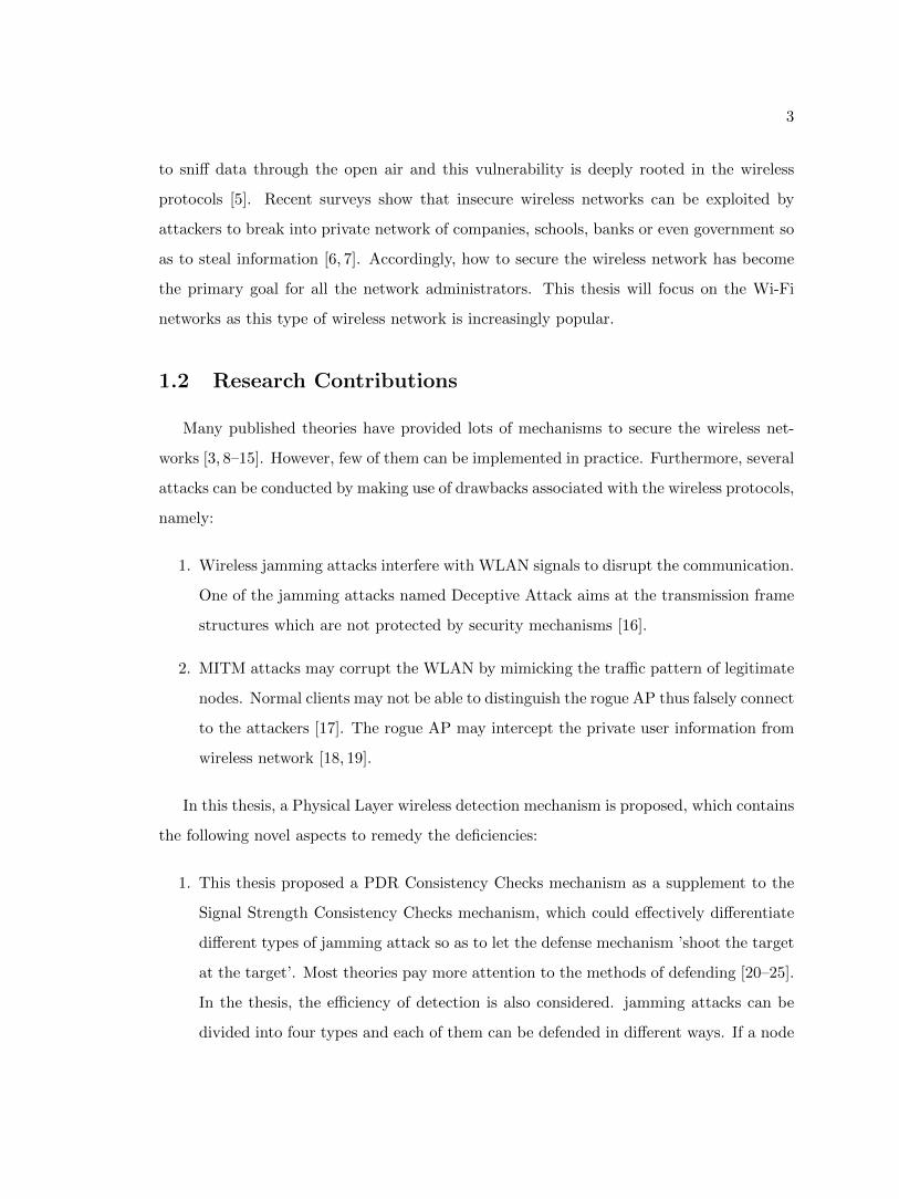
Wireless networks have been becoming more universal throughout the world. Countless
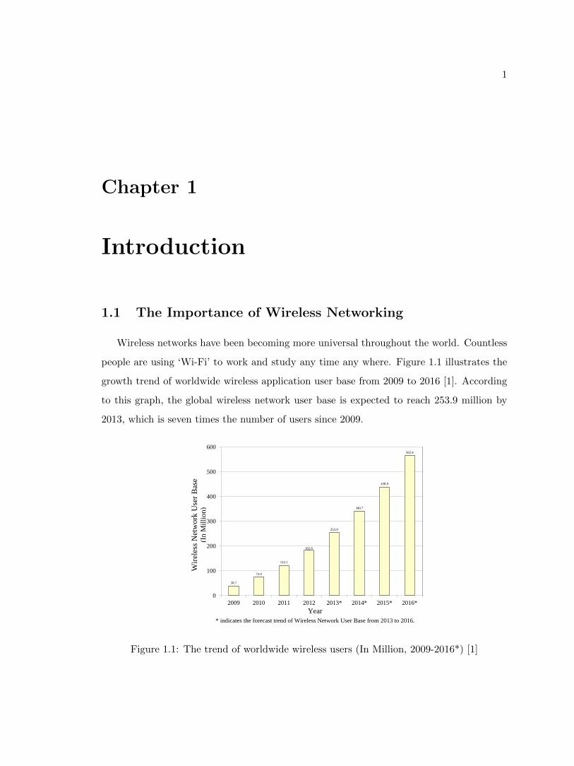
people are using ‘Wi-Fi’ to work and study any time any where. Figure 1.1 illustrates the
growth trend of worldwide wireless application user base from 2009 to 2016 [1]. According
to this graph, the global wireless network user base is expected to reach 253.9 million by
2013, which is seven times the number of users since 2009.
38.7
73.9
122.1
182.8
253.9
340.7
438.9
565.4
0
100
200
300
400
500
600
2009 2010 2011 2012 2013* 2014* 2015* 2016*
Year
* indicates the forecast trend of Wireless Network User Base from 2013 to 2016.
Wir
eles
s N
etw
ork
Use
r B
ase
(In
Mil
lio
n)
Figure 1.1: The trend of worldwide wireless users (In Million, 2009-2016*) [1]
2
Table 1.1: List of IEEE 802.11x protocols [2]
Standards Frequency Speed Rate Modulation Note
802.11 2.4G 2Mbps FHSS/DSSS N/A
802.11a 5G 54Mbps OFDM N/A
802.11b 2.4G 11Mbps DSSS WEP only
802.11g 2.4G 54Mbps OFDM/DSSS Most Popular
802.11i 2.4G N/A N/A WPA/WPA2
802.11e 2.4G N/A N/A Improve QoS
802.11n 2.4G/5G Up to 600Mbps OFDM MIMO
Many wireless products in the market are based on different protocols. For example,
Wi-Fi devices are based on IEEE 802.11x; WPANs (Wireless Personal Area Networks) are
based on IEEE 802.15; WiMax is based on IEEE 802.16 [4]. Among those wireless local
area networks (WLANs), Wi-Fi gets more attention for its stable transmission performance
and relatively low price.
People usually believe that Wi-Fi is the abbreviation of ‘Wireless Fidelity’, which ac-
tually is a common misconception. Wi-Fi is simply a trademark for any WLAN products
based on the IEEE 802.11x standards. The Wi-Fi trademark belongs to Wi-Fi Alliance
which is responsible for promoting Wi-Fi technology and certifying Wi-Fi products.
Since 1997 when IEEE 802.11 protocol was created, the Wi-Fi alliance has played an
important role in improving IEEE 802.11x products. With the help of the Wi-Fi alliance,
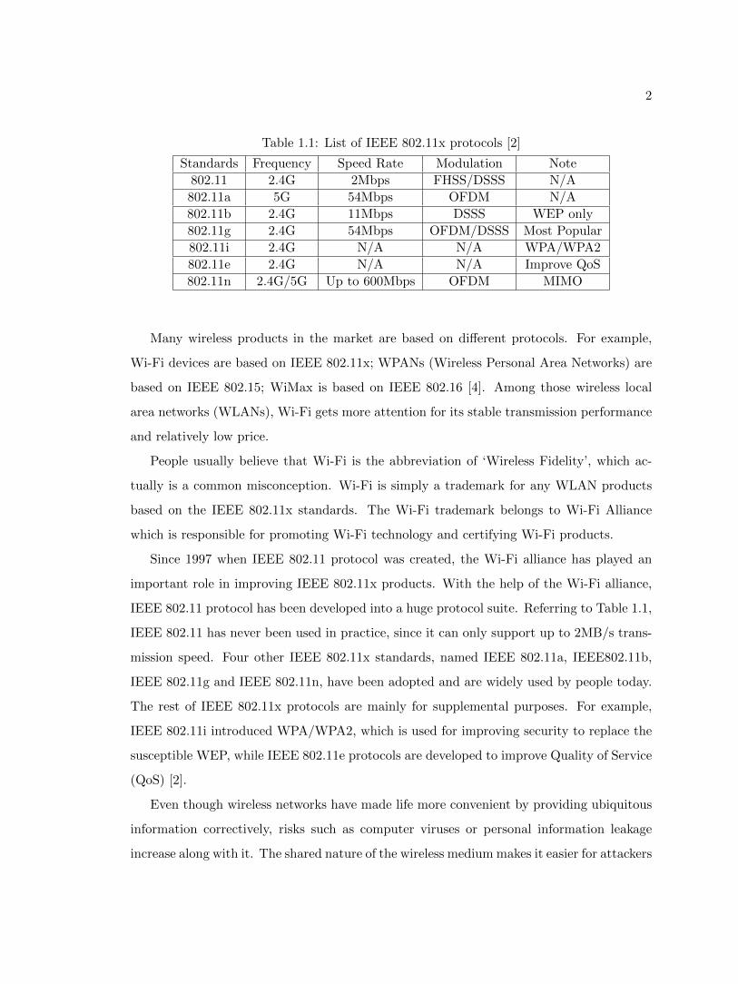
IEEE 802.11 protocol has been developed into a huge protocol suite. Referring to Table 1.1,
IEEE 802.11 has never been used in practice, since it can only support up to 2MB/s trans-
mission speed. Four other IEEE 802.11x standards, named IEEE 802.11a, IEEE802.11b,
IEEE 802.11g and IEEE 802.11n, have been adopted and are widely used by people today.
The rest of IEEE 802.11x protocols are mainly for supplemental purposes. For example,
IEEE 802.11i introduced WPA/WPA2, which is used for improving security to replace the
susceptible WEP, while IEEE 802.11e protocols are developed to improve Quality of Service
(QoS) [2].
Even though wireless networks have made life more convenient by providing ubiquitous
information correctively, risks such as computer viruses or personal information leakage
increase along with it. The shared nature of the wireless medium makes it easier for attackers
3
to sniff data through the open air and this vulnerability is deeply rooted in the wireless
protocols [5]. Recent surveys show that insecure wireless networks can be exploited by
attackers to break into private network of companies, schools, banks or even government so
as to steal information [6, 7]. Accordingly, how to secure the wireless network has become
the primary goal for all the network administrators. This thesis will focus on the Wi-Fi
networks as this type of wireless network is increasingly popular.
1.2 Research Contributions
Many published theories have provided lots of mechanisms to secure the wireless net-
works [3, 8–15]. However, few of them can be implemented in practice. Furthermore, several
attacks can be conducted by making use of drawbacks associated with the wireless protocols,
namely:
1. Wireless jamming attacks interfere with WLAN signals to disrupt the communication.
One of the jamming attacks named Deceptive Attack aims at the transmission frame
structures which are not protected by security mechanisms [16].
2. MITM attacks may corrupt the WLAN by mimicking the traffic pattern of legitimate
nodes. Normal clients may not be able to distinguish the rogue AP thus falsely connect
to the attackers [17]. The rogue AP may intercept the private user information from
wireless network [18, 19].
In this thesis, a Physical Layer wireless detection mechanism is proposed, which contains
the following novel aspects to remedy the deficiencies:
1. This thesis proposed a PDR Consistency Checks mechanism as a supplement to the
Signal Strength Consistency Checks mechanism, which could effectively differentiate
different types of jamming attack so as to let the defense mechanism ’shoot the target
at the target’. Most theories pay more attention to the methods of defending [20–25].
In the thesis, the efficiency of detection is also considered. jamming attacks can be
divided into four types and each of them can be defended in different ways. If a node
4
could determine the specific type of the jamming attack, it would conduct defending
mechanisms better.
2. A lightweight RSSI based detection mechanism of rogue AP is proposed in the thesis.
The word ‘lightweight’ means this mechanism can be easily implemented in practice
with a high accuracy. By processing only RSSI values in sliding window algorithm, the
monitor nodes could detect the existence of the rogue AP. Monitoring only RSSI values
could improve the detection efficiency and reduce the complexity of the algorithm.
Among 1000 experiments, the accuracy could reach 99%.
1.3 Thesis Organization
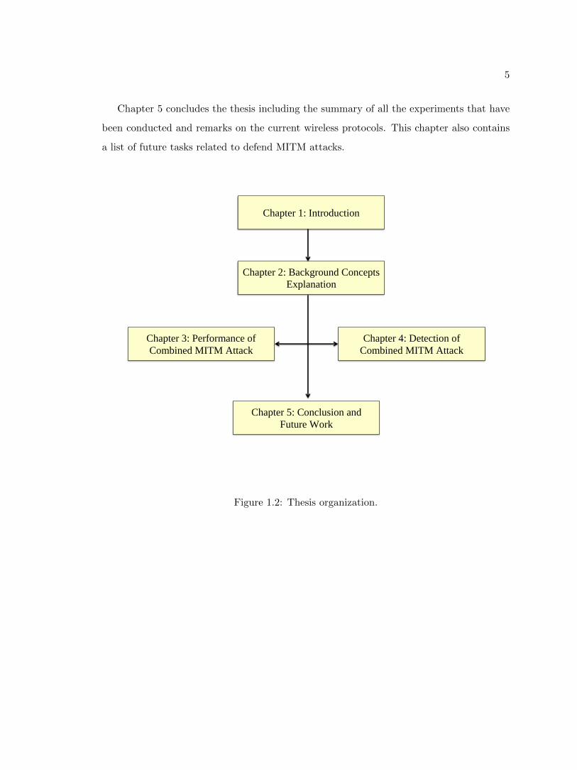
As shown in Figure 1.2, the remainder of the thesis is organized as follows:
In Chapter 2, several important fundamental theories related to computer networks are
introduced. Chapter 2.1 introduces some basic principles of networks. In Chapter 2.2, the
feature of wireless networks is gradually introduced by comparing it with the traditional
Ethernet from Physical Layer to MAC Sublayer. Then in Chapter 2.3, the topology of wire-
less networks is mentioned, which leads to the important concept of wireless network: Basic
Service Set (BSS) and Extended Service Set (ESS). Finally, the chapter briefly introduces
the current security mechanisms and their weaknesses.
Chapter 3 and Chapter 4 dive into two opposite categories. Chapter 3 proposed the
procedures of conducting a combined MITM attacks in details. This combined MITM attack
could be conducted against the majority of common wireless APs successfully. Chapter 3
first introduces the basic procedures for ordinary MITM attack. Then the rest section of
this chapter focuses on how to kidnap the clients by performing jamming attacks.
Chapter 4 focused on the detection mechanism against the MITM attack. The detec-
tion was conducted aiming at two directions. In Chapter 4.1, an algorithm named PDR
Consistency Checks on how to distinguish different types of jamming attacks is introduced.
Chapter 4.2 analyzes the characteristics of RSSI, then detects the rogue AP using time-
varying RSSI parameters. Finally, Chapter 4 dedicates to solve some practical problems
which could improve the accuracy of this RSSI-based detection mechanism.
5
Chapter 5 concludes the thesis including the summary of all the experiments that have
been conducted and remarks on the current wireless protocols. This chapter also contains
a list of future tasks related to defend MITM attacks.
Chapter 1: Introduction
Chapter 2: Background Concepts
Explanation
Chapter 3: Performance of
Combined MITM Attack
Chapter 4: Detection of
Combined MITM Attack
Chapter 5: Conclusion and
Future Work
Figure 1.2: Thesis organization.
6
Chapter 2
Background
2.1 Computer Networks
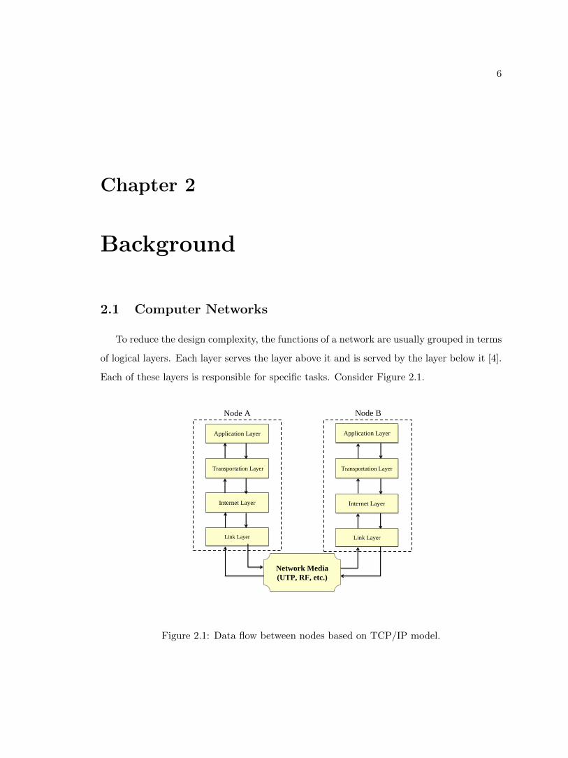
To reduce the design complexity, the functions of a network are usually grouped in terms
of logical layers. Each layer serves the layer above it and is served by the layer below it [4].
Each of these layers is responsible for specific tasks. Consider Figure 2.1.
Application Layer
Transportation Layer
Internet Layer
Link Layer
Application Layer
Transportation Layer
Internet Layer
Network Media
(UTP, RF, etc.)
Link Layer
Node A Node B
Figure 2.1: Data flow between nodes based on TCP/IP model.
7
Figure 2.1 illustrates a simple transmission process between two nodes in a network
based on the TCP/IP model. Both Node A and Node B are transmitters as well as receivers.
When Node A wants to send a message to Node B, i.e., Node A is the transmitter, the
application layer of Node A will generate the message and pass it to the transportation
layer. After creating a port on the Node A, the transportation layer pass the message to
the Internet layer which will locate the position of Node B by IP address. Then the Internet
layer would send the message to the link layer. In the link layer, the message is transformed
into binary codes, e.g., 001100 and sent out through physical medium including, but not
limited to, Unshielded Twisted Pair (UTP), coaxial cable , optical fiber or radio waves.
The physical medium could direct the signal to the link layer of Node B, which will perform
some integrity checks after receiving the binary codes. After that the link layer of Node B
pass the codes to the upper layers. The Internet/transportation layers restore the message
and send it to the application Layer which could show the content of this message to Node
B. Similarly, Node B could send messages to Node A in the same way [4].
Among varieties of network models, a popular one named Open Systems Interconnection
(OSI) model was created by International Organization for Standardization (ISO) [26]. In
an OSI model, a network is divided into seven layers instead of four layers in TCP/IP
model. This seven layers model is convenient to describe the functions of networks, while
four layers TCP/IP model is easier to achieve the functions of networks in reality. Therefore,
TCP/IP model is derived form OSI model but less complicated. Figure 2.2 illustrates the
correspondence between TCP/IP model and OSI model.
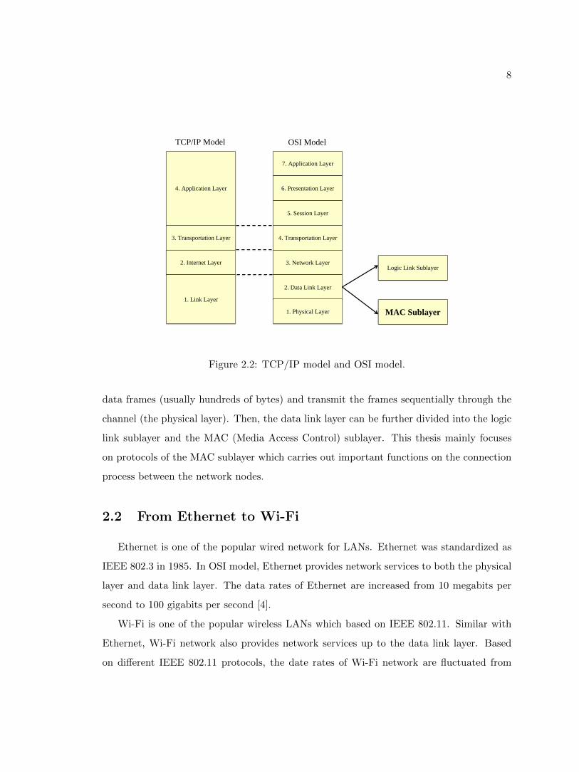
In Figure 2.2, the application layer of TCP/IP model is divided into three layers of
OSI model, i.e. The application layer, the presentation layer and the session layer. The
link layer of TCP/IP model can be divided into the date link layer and the physical layer
in OSI Model. As the signal noise exists in the common physical channel, messages are
difficult to be sent from one node to another directly without corrupting. If some part
of the message was damaged by the interference from noise or other signals, a duplicate
message has to be retransmitted, which may result in a serious delay and enormous waste
of bandwidth. Under such circumstances, the data link layer of OSI model was designed to
solve the problem by further breaking up the segments received from the network layer into
8
7. Application Layer
6. Presentation Layer
5. Session Layer
4. Transportation Layer
3. Network Layer
2. Data Link Layer
1. Physical Layer
4. Application Layer
3. Transportation Layer
2. Internet Layer
1. Link Layer
Logic Link Sublayer
MAC Sublayer
TCP/IP Model OSI Model
Figure 2.2: TCP/IP model and OSI model.
data frames (usually hundreds of bytes) and transmit the frames sequentially through the
channel (the physical layer). Then, the data link layer can be further divided into the logic
link sublayer and the MAC (Media Access Control) sublayer. This thesis mainly focuses
on protocols of the MAC sublayer which carries out important functions on the connection
process between the network nodes.
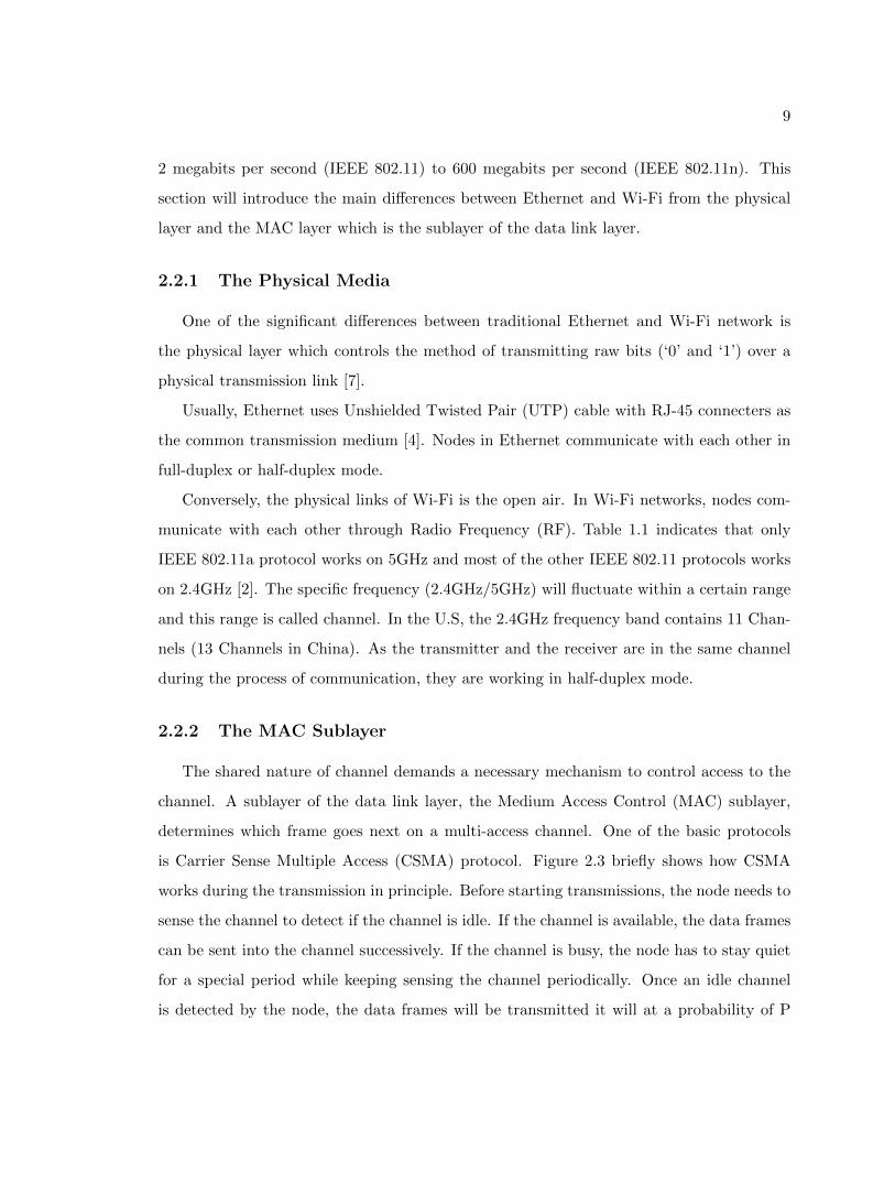
2.2 From Ethernet to Wi-Fi
Ethernet is one of the popular wired network for LANs. Ethernet was standardized as
IEEE 802.3 in 1985. In OSI model, Ethernet provides network services to both the physical
layer and data link layer. The data rates of Ethernet are increased from 10 megabits per
second to 100 gigabits per second [4].
Wi-Fi is one of the popular wireless LANs which based on IEEE 802.11. Similar with
Ethernet, Wi-Fi network also provides network services up to the data link layer. Based
on different IEEE 802.11 protocols, the date rates of Wi-Fi network are fluctuated from
9
2 megabits per second (IEEE 802.11) to 600 megabits per second (IEEE 802.11n). This
section will introduce the main differences between Ethernet and Wi-Fi from the physical
layer and the MAC layer which is the sublayer of the data link layer.
2.2.1 The Physical Media
One of the significant differences between traditional Ethernet and Wi-Fi network is
the physical layer which controls the method of transmitting raw bits (‘0’ and ‘1’) over a
physical transmission link [7].
Usually, Ethernet uses Unshielded Twisted Pair (UTP) cable with RJ-45 connecters as
the common transmission medium [4]. Nodes in Ethernet communicate with each other in
full-duplex or half-duplex mode.
Conversely, the physical links of Wi-Fi is the open air. In Wi-Fi networks, nodes com-
municate with each other through Radio Frequency (RF). Table 1.1 indicates that only
IEEE 802.11a protocol works on 5GHz and most of the other IEEE 802.11 protocols works
on 2.4GHz [2]. The specific frequency (2.4GHz/5GHz) will fluctuate within a certain range
and this range is called channel. In the U.S, the 2.4GHz frequency band contains 11 Chan-
nels (13 Channels in China). As the transmitter and the receiver are in the same channel
during the process of communication, they are working in half-duplex mode.
2.2.2 The MAC Sublayer
The shared nature of channel demands a necessary mechanism to control access to the
channel. A sublayer of the data link layer, the Medium Access Control (MAC) sublayer,
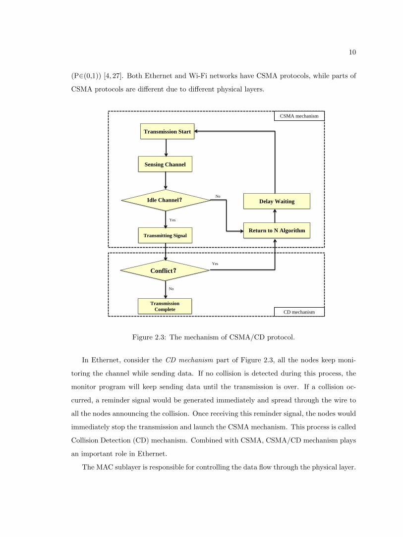
determines which frame goes next on a multi-access channel. One of the basic protocols
is Carrier Sense Multiple Access (CSMA) protocol. Figure 2.3 briefly shows how CSMA
works during the transmission in principle. Before starting transmissions, the node needs to
sense the channel to detect if the channel is idle. If the channel is available, the data frames
can be sent into the channel successively. If the channel is busy, the node has to stay quiet
for a special period while keeping sensing the channel periodically. Once an idle channel
is detected by the node, the data frames will be transmitted it will at a probability of P
10
(P∈(0,1)) [4, 27]. Both Ethernet and Wi-Fi networks have CSMA protocols, while parts of
CSMA protocols are different due to different physical layers.
No
Yes
No
Yes
Sensing Channel
Idle Channel?
Return to N Algorithm
Delay Waiting
Transmitting Signal
Conflict?
Transmission
Complete
Transmission Start
CSMA mechanism
CD mechanism
Figure 2.3: The mechanism of CSMA/CD protocol.
In Ethernet, consider the CD mechanism part of Figure 2.3, all the nodes keep moni-
toring the channel while sending data. If no collision is detected during this process, the
monitor program will keep sending data until the transmission is over. If a collision oc-
curred, a reminder signal would be generated immediately and spread through the wire to
all the nodes announcing the collision. Once receiving this reminder signal, the nodes would
immediately stop the transmission and launch the CSMA mechanism. This process is called
Collision Detection (CD) mechanism. Combined with CSMA, CSMA/CD mechanism plays
an important role in Ethernet.
The MAC sublayer is responsible for controlling the data flow through the physical layer.
11
Since the transmission medium has been changed from ‘wired’ into ‘wireless’, the collision
processing mechanism should also be modified accordingly [28].
One of the reasons is that, unlike the wired transmission medium in Ethernet along
which the collision reminder signal could be transmitted to the nodes, a wireless network
has no guidable route for the collision reminder signal to transmit. In other words, the
wireless collision happened in the open air and there is no way for the reminder signal to
send back. Therefore, even if a collision reminder signal can be generated successfully after
a collision, the nodes within this wireless network have no way to detect it.
Another reason is that in a wireless environment, it would be difficult for the transmitter
to decide if the receiver is actually idle even though the channel between them may be
available. Thus multiple transmissions at the same time may corrupt each other. In a
wireless network, what really matters is not the status of the transmitter but the status of
the receiver. Two of the common wireless transmission problems are hidden station problem
and exposed station problem.
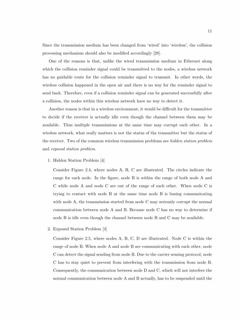
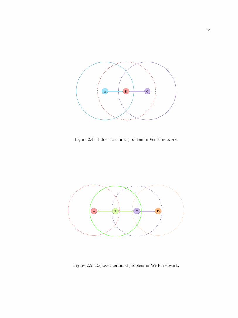
1. Hidden Station Problem [4]
Consider Figure 2.4, where nodes A, B, C are illustrated. The circles indicate the
range for each node. In the figure, node B is within the range of both node A and
C while node A and node C are out of the range of each other. When node C is
trying to contact with node B at the same time node B is busing communicating
with node A, the transmission started from node C may seriously corrupt the normal
communication between node A and B. Because node C has no way to determine if
node B is idle even though the channel between node B and C may be available.
2. Exposed Station Problem [4]
Consider Figure 2.5, where nodes A, B, C, D are illustrated. Node C is within the
range of node B. When node A and node B are communicating with each other, node
C can detect the signal sending from node B. Due to the carrier sensing protocol, node
C has to stay quiet to prevent from interfering with the transmission from node B.
Consequently, the communication between node D and C, which will not interfere the
normal communication between node A and B actually, has to be suspended until the
12
C B A
Figure 2.4: Hidden terminal problem in Wi-Fi network.
D C B A
Figure 2.5: Exposed terminal problem in Wi-Fi network.
13
activities of node B are finished. In this situation, one normal communication affects
another communication unnecessarily.
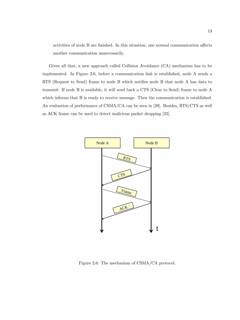
Given all that, a new approach called Collision Avoidance (CA) mechanism has to be
implemented. In Figure 2.6, before a communication link is established, node A sends a
RTS (Request to Send) frame to node B which notifies node B that node A has data to
transmit. If node B is available, it will send back a CTS (Clear to Send) frame to node A
which informs that B is ready to receive message. Then the communication is established.
An evaluation of performance of CSMA/CA can be seen in [29]. Besides, RTS/CTS as well
as ACK frame can be used to detect malicious packet dropping [22].
Node A Node B
t
Figure 2.6: The mechanism of CSMA/CA protocol.
14
2.3 Topology in Wi-Fi
Topology indicates the physical or logical relationships between different network nodes.
Currently, there are five types of topologies in the wired network, i.e., bus topology, ring
topology, star topology, tree topology as well as mesh topology. In wireless networks,
however, there are only two types of topologies: star topology and mesh topology [30].
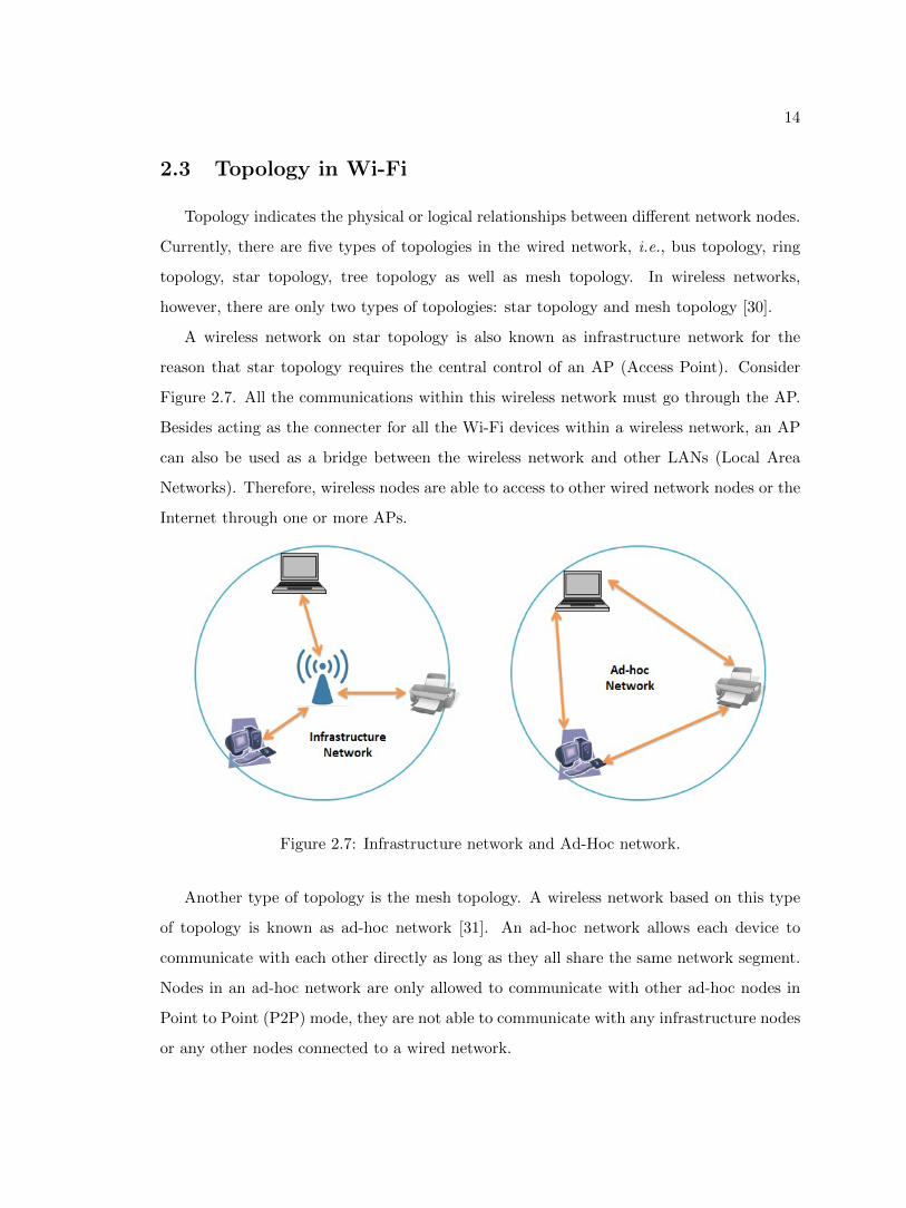
A wireless network on star topology is also known as infrastructure network for the
reason that star topology requires the central control of an AP (Access Point). Consider
Figure 2.7. All the communications within this wireless network must go through the AP.
Besides acting as the connecter for all the Wi-Fi devices within a wireless network, an AP
can also be used as a bridge between the wireless network and other LANs (Local Area
Networks). Therefore, wireless nodes are able to access to other wired network nodes or the
Internet through one or more APs.
Figure 2.7: Infrastructure network and Ad-Hoc network.
Another type of topology is the mesh topology. A wireless network based on this type
of topology is known as ad-hoc network [31]. An ad-hoc network allows each device to
communicate with each other directly as long as they all share the same network segment.
Nodes in an ad-hoc network are only allowed to communicate with other ad-hoc nodes in
Point to Point (P2P) mode, they are not able to communicate with any infrastructure nodes
or any other nodes connected to a wired network.
15
As was stated above, infrastructure networks are more suitable for home, small offices.
Therefore, most wireless LANs adopt star topology. Chapter 3 will introduce a combined
man-in-the-middle attack which can be conducted against the infrastructure Wi-Fi net-
works. The MITM attack could not only result in a network meltdown but also intercept
the private information of the clients. In Chapter 4, an RSSI based MITM attack detection
mechanism is implemented. As all the legitimate Wi-Fi networks may be affected by the
MITM attack, the detection mechanism is carried out based on an ad-hoc network.
2.3.1 Basic Service Set
The Basic Service Set (BSS) is a set of all stations consisting of at most one single
wireless AP. In Figure 2.7, both types of wireless networks, infrastructure networks and
ad-hoc networks belong to the BSS. Accordingly, the BSS can be divided into two types,
i.e., the infrastructure BSS and the Independent BSS (also referred to as IBSS). An ad-hoc
network is an IBSS because it cannot connect to any other basic service set. Similarly, an
infrastructure network is an infrastructure BSS.
Each BSS is uniquely identified by a basic service set identification (BSSID), usually the
‘MAC Address’ of the AP, generated by the 24 bits Organization Unique Identifier (OUI).
This 24 bits OUI usually indicates the NIC (Network Interface Card) manufacturers. In
other words, the first three bytes of the MAC addresses on the NICs of the same brand
should be the same. This characteristic can be used to perform multi-point jamming attacks.
More details on jamming attacks will be introduced in Chapter 3.
2.3.2 Extended Service Set
Figure 2.8 shows a concept of the Extended Service Set (ESS). In an ESS, multiple APs
are connected to the wired portion of the network, operation from the same router. All
those APs have the same ESSID which is the identifier of the network. The key point is all
the APs are controlled by the same router. That is, in an ESS all APs must be within the
same subnet. The ESSID is often a up to 32-byte alphanumeric key identifying the name
of the WLANs. For the wireless devices in a WLAN to communicate with each other, all
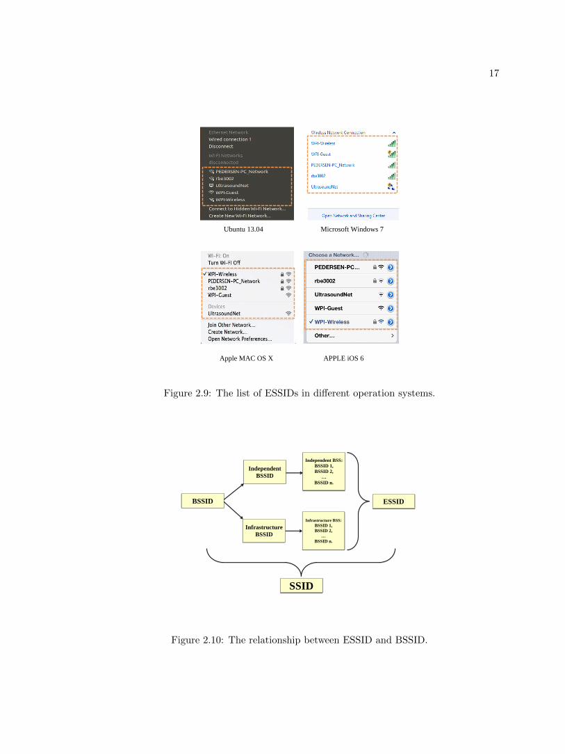
devices must be configured with the same ESSID. Figure 2.9 shows how ESSIDs look like

16
Internet
ESSID: WPI-Wireless BSSID: 78:19:F7:77:6F:82
ESSID: WPI-Wireless BSSID: 78:19:F7:77: FB: 82
ESSID: WPI-Wireless BSSID: 78:19:F7:77:8D: 42
Figure 2.8: The Extended Service Set (ESS).
in several popular operation systems.
People may feel confused about the concepts of SSID, BSSID as well as ESSID. Consider
Figure 2.10, SSID is consist of both BSSID and ESSID. By way of analogy, people usually
have two identify labels in the real world. One is the ‘name’ which is easy to remember,
another one is a unique identifier such as the ‘Social Security Number (SSN)’ in the U.S.
The network world has the same naming rules to identify network, i.e., ESSID and BSSID.
Both the ESSID and BSSID are the identifiers for a wireless network. Just like the ‘name’
in the real world, ESSID is usually a human readable name associate with a Wi-Fi network
which can be considered as the ‘network name’. As the ESSID can be modified at any time,
it is necessary to find another identifier which is unique in the world and normally cannot
be modified. A MAC address in a NIC is a unique identifier. Under normal conditions,
MAC address is unique and prohibited from modified. Therefore, the central AP usually
chooses its MAC address as the BSSID.
An ESSID may contain several BSSIDs. Both ESSID and BSSID are composed to SSID.
In an infrastructure mode network, all the devices associated with the AP are considered
17
Ubuntu 13.04 Microsoft Windows 7
Apple MAC OS X APPLE iOS 6
Figure 2.9: The list of ESSIDs in different operation systems.
SSID
Independent BSS:
BSSID 1,
BSSID 2,
…
BSSID n.
BSSID ESSID
Independent
BSSID
Infrastructure
BSSID
Infrastructure BSS:
BSSID 1,
BSSID 2,
…
BSSID n.
Figure 2.10: The relationship between ESSID and BSSID.
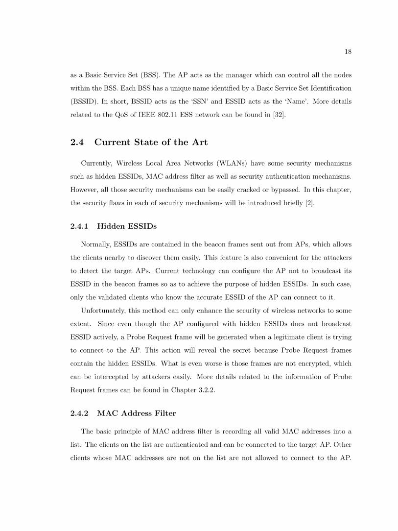
18
as a Basic Service Set (BSS). The AP acts as the manager which can control all the nodes
within the BSS. Each BSS has a unique name identified by a Basic Service Set Identification
(BSSID). In short, BSSID acts as the ‘SSN’ and ESSID acts as the ‘Name’. More details
related to the QoS of IEEE 802.11 ESS network can be found in [32].
2.4 Current State of the Art
Currently, Wireless Local Area Networks (WLANs) have some security mechanisms
such as hidden ESSIDs, MAC address filter as well as security authentication mechanisms.
However, all those security mechanisms can be easily cracked or bypassed. In this chapter,
the security flaws in each of security mechanisms will be introduced briefly [2].
2.4.1 Hidden ESSIDs
Normally, ESSIDs are contained in the beacon frames sent out from APs, which allows
the clients nearby to discover them easily. This feature is also convenient for the attackers
to detect the target APs. Current technology can configure the AP not to broadcast its
ESSID in the beacon frames so as to achieve the purpose of hidden ESSIDs. In such case,
only the validated clients who know the accurate ESSID of the AP can connect to it.
Unfortunately, this method can only enhance the security of wireless networks to some
extent. Since even though the AP configured with hidden ESSIDs does not broadcast
ESSID actively, a Probe Request frame will be generated when a legitimate client is trying
to connect to the AP. This action will reveal the secret because Probe Request frames
contain the hidden ESSIDs. What is even worse is those frames are not encrypted, which
can be intercepted by attackers easily. More details related to the information of Probe
Request frames can be found in Chapter 3.2.2.
2.4.2 MAC Address Filter
The basic principle of MAC address filter is recording all valid MAC addresses into a
list. The clients on the list are authenticated and can be connected to the target AP. Other
clients whose MAC addresses are not on the list are not allowed to connect to the AP.
19
This technique seems secure enough since MAC addresses should be unique as mentioned
in Chapter 2.3.2. Unfortunately, just like the Maginot Line, the MAC address filters can
be bypassed.
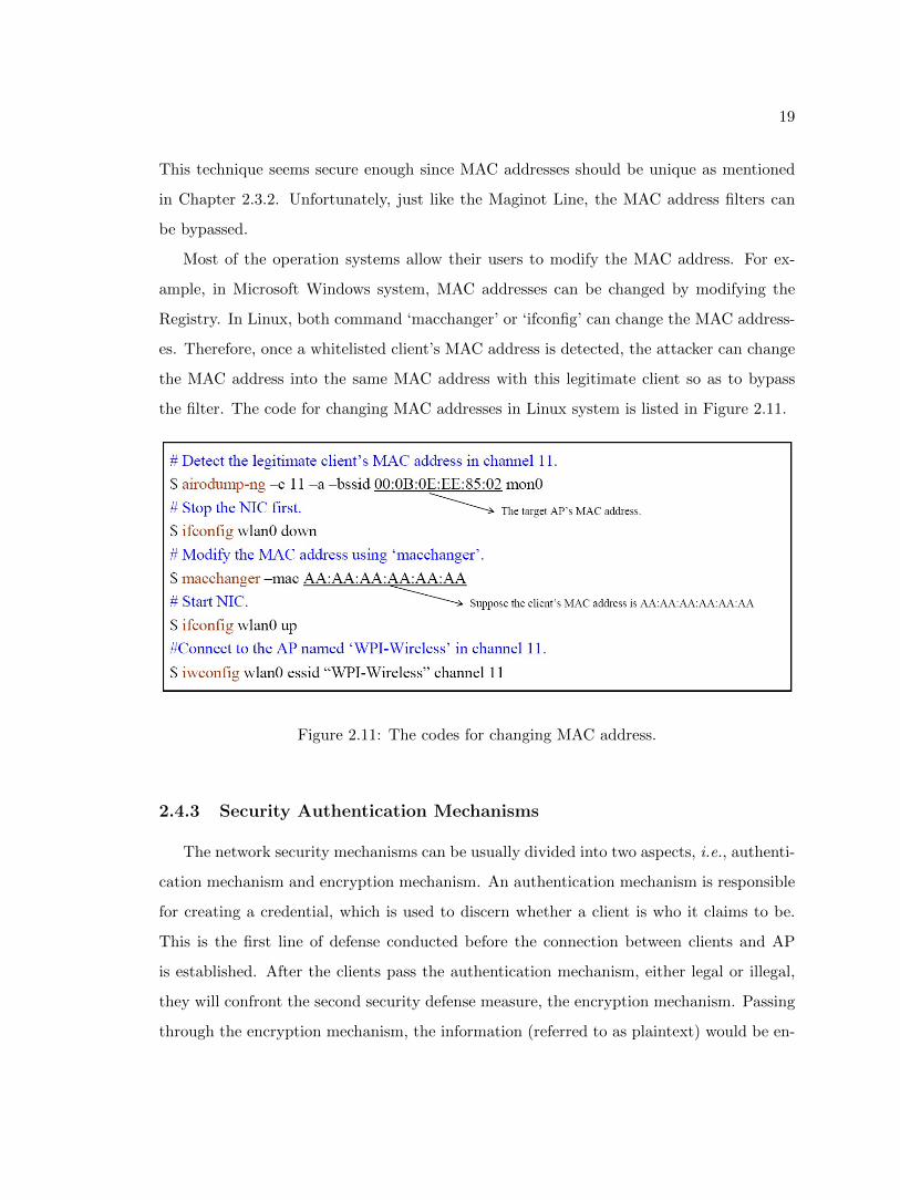
Most of the operation systems allow their users to modify the MAC address. For ex-
ample, in Microsoft Windows system, MAC addresses can be changed by modifying the
Registry. In Linux, both command ‘macchanger’ or ‘ifconfig’ can change the MAC address-
es. Therefore, once a whitelisted client’s MAC address is detected, the attacker can change
the MAC address into the same MAC address with this legitimate client so as to bypass
the filter. The code for changing MAC addresses in Linux system is listed in Figure 2.11.
Figure 2.11: The codes for changing MAC address.
2.4.3 Security Authentication Mechanisms
The network security mechanisms can be usually divided into two aspects, i.e., authenti-
cation mechanism and encryption mechanism. An authentication mechanism is responsible
for creating a credential, which is used to discern whether a client is who it claims to be.
This is the first line of defense conducted before the connection between clients and AP
is established. After the clients pass the authentication mechanism, either legal or illegal,
they will confront the second security defense measure, the encryption mechanism. Passing
through the encryption mechanism, the information (referred to as plaintext) would be en-
20
crypted by an encryption algorithm. The encryption algorithm can turn the plaintext into
the unreadable ciphertext so that eavesdroppers cannot read it [33].
At present, mainly security mechanisms of Wi-Fi networks are WEP, WPA/WPA2-
personal, WPA/WPA2-enterprise. This chapter will briefly analyze the weaknesses of each
security mechanisms from authentication aspect and encryption aspect.
WEP
Wired Equivalent Privacy (WEP) is the first applied security mechanism for Wi-Fi
networks which was adopted as the only privacy component of IEEE 802.11 and IEEE
802.11b protocols. Just as the name implies, the design purpose of WEP is to provide data
confidentiality as secure as a wired connection. However, WEP has been proved to have
many weaknesses [25].
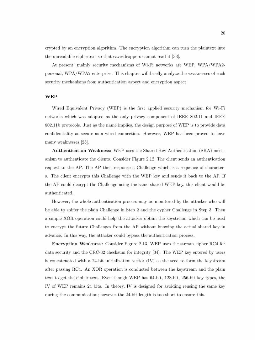
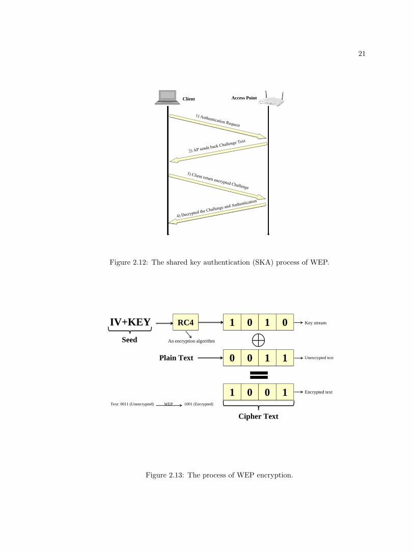
Authentication Weakness: WEP uses the Shared Key Authentication (SKA) mech-
anism to authenticate the clients. Consider Figure 2.12, The client sends an authentication
request to the AP. The AP then response a Challenge which is a sequence of character-
s. The client encrypts this Challenge with the WEP key and sends it back to the AP. If
the AP could decrypt the Challenge using the same shared WEP key, this client would be
authenticated.
However, the whole authentication process may be monitored by the attacker who will
be able to sniffer the plain Challenge in Step 2 and the cypher Challenge in Step 3. Then
a simple XOR operation could help the attacker obtain the keystream which can be used
to encrypt the future Challenges from the AP without knowing the actual shared key in
advance. In this way, the attacker could bypass the authentication process.
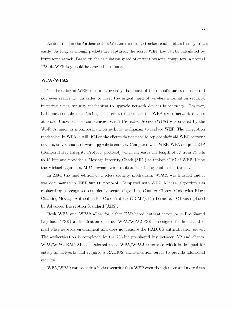
Encryption Weakness: Consider Figure 2.13, WEP uses the stream cipher RC4 for
data security and the CRC-32 checksum for integrity [34]. The WEP key entered by users
is concatenated with a 24-bit initialization vector (IV) as the seed to form the keystream
after passing RC4. An XOR operation is conducted between the keystream and the plain
text to get the cipher text. Even though WEP has 64-bit, 128-bit, 256-bit key types, the
IV of WEP remains 24 bits. In theory, IV is designed for avoiding reusing the same key
during the communication; however the 24-bit length is too short to ensure this.
21
Client Access Point
Figure 2.12: The shared key authentication (SKA) process of WEP.
An encryption algorithm
Text: 0011 (Unencrypted) WEP 1001 (Encrypted)
0 0 1 1
1 0 0 1
Plain Text
IV+KEY RC4 1 0 1 0
Seed
Cipher Text
Encrypted text
Unencrypted text
Key stream
Figure 2.13: The process of WEP encryption.
22
As described in the Authentication Weakness section, attackers could obtain the keystream
easily. As long as enough packets are captured, the secret WEP key can be calculated by
brute force attack. Based on the calculation speed of current personal computers, a normal
128-bit WEP key could be cracked in minutes.
WPA/WPA2
The breaking of WEP is so unexpectedly that most of the manufacturers or users did
not even realize it. In order to meet the urgent need of wireless information security,
inventing a new security mechanism to upgrade network devices is necessary. However,
it is unreasonable that forcing the users to replace all the WEP series network devices
at once. Under such circumstances, Wi-Fi Protected Access (WPA) was created by the
Wi-Fi Alliance as a temporary intermediate mechanism to replace WEP. The encryption
mechanism in WPA is still RC4 so the clients do not need to replace their old WEP network
devices, only a small software upgrade is enough. Compared with WEP, WPA adopts TKIP
(Temporal Key Integrity Protocol protocol) which increases the length of IV from 24 bits
to 48 bits and provides a Message Integrity Check (MIC) to replace CRC of WEP. Using
the Michael algorithm, MIC prevents wireless data from being modified in transit.
In 2004, the final edition of wireless security mechanism, WPA2, was finished and it
was documented in IEEE 802.11i protocol. Compared with WPA, Michael algorithm was
replaced by a recognized completely secure algorithm, Counter Cipher Mode with Block
Chaining Message Authentication Code Protocol (CCMP). Furthermore, RC4 was replaced
by Advanced Encryption Standard (AES).
Both WPA and WPA2 allow for either EAP-based authentication or a Pre-Shared
Key-based(PSK) authentication scheme. WPA/WPA2-PSK is designed for home and s-
mall office network environment and does not require the RADIUS authentication server.
The authentication is completed by the 256-bit pre-shared key between AP and clients.
WPA/WPA2-EAP AP also referred to as WPA/WPA2-Enterprise which is designed for
enterprise networks and requires a RADIUS authentication server to provide additional
security.
WPA/WPA2 can provide a higher security than WEP even though more and more flaws
23
KEY
SSID
SHA-1
(HASH)
PMK
ANounce
Client MAC
Address
SNounce
AP MAC
Address
PTK Pairwise Transient Key
Plain Text
TKIP/AES MIC Cipher Text
Four-Way Handshake
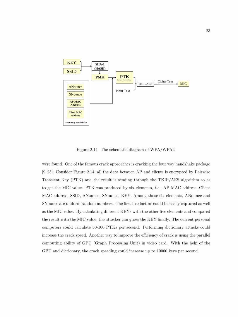
Figure 2.14: The schematic diagram of WPA/WPA2.
were found. One of the famous crack approaches is cracking the four way handshake package
[9, 25]. Consider Figure 2.14, all the data between AP and clients is encrypted by Pairwise
Transient Key (PTK) and the result is sending through the TKIP/AES algorithm so as
to get the MIC value. PTK was produced by six elements, i.e., AP MAC address, Client
MAC address, SSID, ANounce, SNounce, KEY. Among those six elements, ANounce and
SNounce are uniform random numbers. The first five factors could be easily captured as well
as the MIC value. By calculating different KEYs with the other five elements and compared
the result with the MIC value, the attacker can guess the KEY finally. The current personal
computers could calculate 50-100 PTKs per second. Performing dictionary attacks could
increase the crack speed. Another way to improve the efficiency of crack is using the parallel
computing ability of GPU (Graph Processing Unit) in video card. With the help of the
GPU and dictionary, the crack speeding could increase up to 10000 keys per second.
24
2.5 Chapter Summary
The chapter introduces some fundamental principles of Wi-Fi networks. The content is
summarized as follows:
1. The functions of networks are divided into logical layers. Each layer serves the layer
above it and is served by the layer below it. To better understand the functions in
different layers, the four-layer TCP/IP model can spread to seven-layer OSI model.
2. Compared with wired network, the significant difference of Wi-Fi networks in Physical
Layer is adopting radio wave as the transmission medium. Correspondingly, the pro-
tocol of Wi-Fi networks in MAC sublayer adopts CSMA/CA instead of CSMA/CD
for Ethernet for the reason that the transmission medium of wireless network, i.e.,
electromagnetic wave, is not guidable.
3. Wi-Fi networks have only two type of topologies,i.e., Star topology and Mesh topology,
compared with five topologies in wired networks. Wi-Fi network in Star topology is
called infrastructure network and in Mesh topology is called Ad-Hoc network.
4. Both infrastructure networks and ad-hoc networks belong to Basic Service Set(BSS)
and normally use the MAC address as the BSSID. Several BSS connected together
could form ESS which use uniform ESSID. Both BSSID and ESSID compose to SSID.
5. Hidden ESSIDs can be revealed by intercepting Probe Request frames. Changing
MAC addresses could bypass the MAC address filter. Both authentication and en-
cryption mechanisms in WEP have been proved insecure. The weak passwords in
WPA/WPA2-Personal can be disclosed by attacking the four-way handshake packets.
Next chapter will continue analyzing the drawbacks on the protocols of MAC sublayer.
Then a combined MITM attack is conducted by exploiting those drawbacks. This combined
MITM attack could not only bypass the security mechanisms but also sniff the private
information in the Wi-Fi network.
25
Chapter 3
The Performance of Combined
Man-In-The-Middle Attack
3.1 Introduction
The transmission channel of Wi-Fi networks is the open air, which means the infor-
mation packets are all over around people and anyone can intercept the packets. In this
case, encrypting the data packets seems the only way to secure the information. Indeed,
WPA/WPA2 is hard to crack, which is secure enough to block the majority of attackers.
However, an advanced encryption algorithm, as well as an authentication mechanism, is
hard to protect the information from being intercepted by MITM attacks.
Next, a combined Man-in-The-Middle (MITM) attack will be proposed. This type of
attack is able to steal the information no matter what type of security mechanism is being
implemented. During the MITM attack, the attacker creates a separate connection with
the clients and replays transmission packets, making them believe that they are connecting
to the Internet directly, while actually the whole communication process is manipulated by
the attacker [6]. The combined MITM attack includes the configuration of DHCP server,
the creating of a rogue AP and multi-point jamming attacks for kidnaping the clients to
increase the success rate.
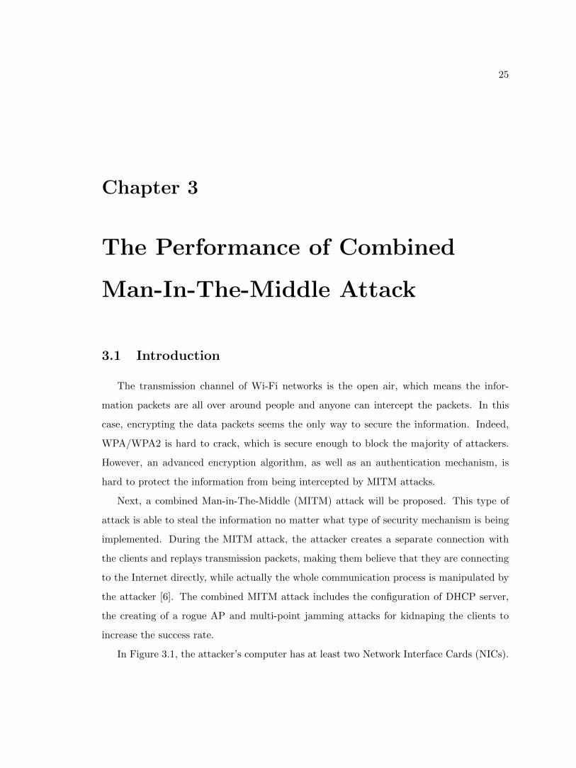
In Figure 3.1, the attacker’s computer has at least two Network Interface Cards (NICs).
26
Internet
The legitimate client
The legitimate AP
The Attacker
(Conducting
Man-In-The-Middle
Attacks)
The fake AP
(Broadcasting the
same ESSID as the
legitimate AP)
Figure 3.1: The basic model of Man-In-The-Middle attack
One is connected to the Internet using either a wire or a wireless LAN, the other one is
used to create a rogue AP. This rogue AP will broadcast the same SSID as the legitimate
APs nearby. Normally the attacker may either wait clients accidently connect to the rogue
AP or attract them to connect by using a higher signal strength. Besides, a multi-point
jamming attack is conducted against the legitimate APs to obtain a better performance of
MITM attack.
Antenna 1
Antenna 2 Antenna 3
Wireless NIC
BackTrack 5 system
Figure 3.2: The devices for MITM attack
27
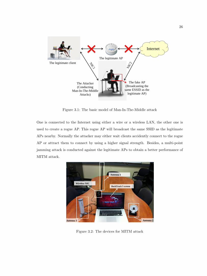
Figure 3.2 shows the basic equipments needed in the combined MITM attack. The
attacker test bed includes powerful antennas, a computer with BackTrack system as well as
an extra wireless NIC, which supports packets injection.
The target test bed is based on the wireless network of WPI, which uses WPA2-
Enterprise as the authentication mechanism. From a safety point of view, WPI forbids
anyone to install a hardware AP either through the wired LAN or in repeater mode with
the legitimated wireless APs. In a word, any network devices are not allowed to connect
with WPI network. Furthermore, the RADIUS server of WPA2-Enterprise is hard to at-
tack. Even though the wireless network environment of WPI is so secure, the combined
MITM attack is still able to intercept private data packets from clients.
3.2 The Implementation of MITM attack
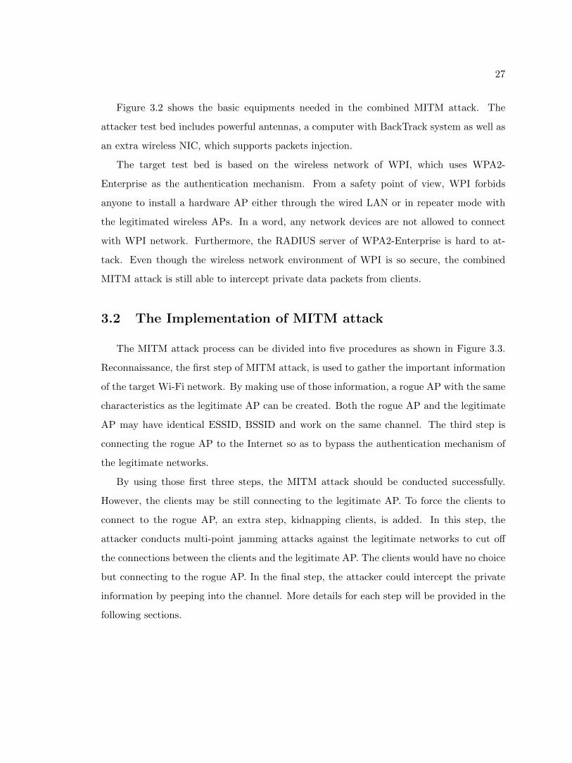
The MITM attack process can be divided into five procedures as shown in Figure 3.3.
Reconnaissance, the first step of MITM attack, is used to gather the important information
of the target Wi-Fi network. By making use of those information, a rogue AP with the same
characteristics as the legitimate AP can be created. Both the rogue AP and the legitimate
AP may have identical ESSID, BSSID and work on the same channel. The third step is
connecting the rogue AP to the Internet so as to bypass the authentication mechanism of
the legitimate networks.
By using those first three steps, the MITM attack should be conducted successfully.
However, the clients may be still connecting to the legitimate AP. To force the clients to
connect to the rogue AP, an extra step, kidnapping clients, is added. In this step, the
attacker conducts multi-point jamming attacks against the legitimate networks to cut off
the connections between the clients and the legitimate AP. The clients would have no choice
but connecting to the rogue AP. In the final step, the attacker could intercept the private
information by peeping into the channel. More details for each step will be provided in the
following sections.
28
1. Reconnaissance
2. Rogue Access Point
3. Bypass Security
5. Peep into the Channel
4. Kidnap Clients Target Connect to
the Rogue AP?
Yes
No
Figure 3.3: The procedures of MITM attack
3.2.1 Reconnaissance
Normal wireless NICs have three major modes, i.e., managed mode, ad-hoc mode and
monitor mode. Managed mode is used to connect with a wireless AP. Ad-hoc mode is for the
ad-hoc network. In a Local Area Network (LAN), the transmission packets are transmitted
in the form of broadcast, which means the packets will pass by all the clients in the same
network segment. Only the client with the specified destination MAC addresses is able to
accept the data. To monitor all data in a Wi-Fi network, the mode of NICs needs to be
changed into monitor mode (promiscuous mode in Ethernet). In the monitor mode, the
NIC of the attacker will be able to intercept all the packets in the network. In Linux, the
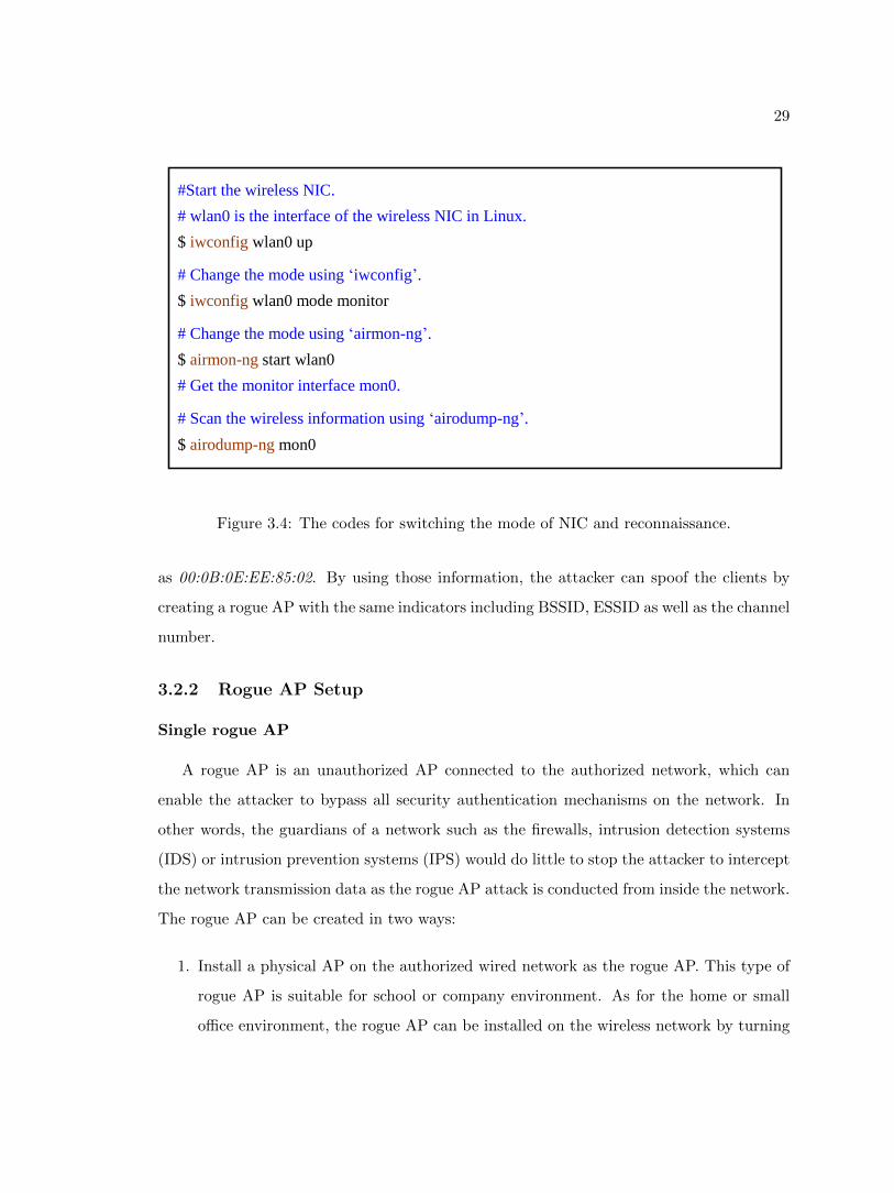
mode of NICs can be switched using iwconfig or airmon-ng. Figure 3.4 shows the codes for
switching the mode of NIC and conducting reconnaissance using command airodump-ng.
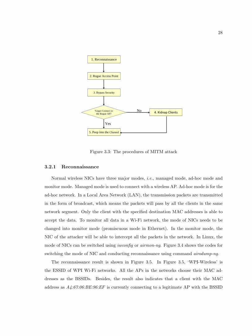
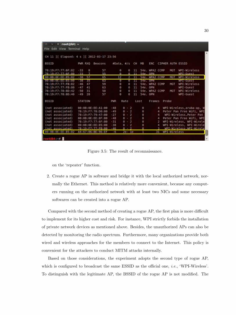
The reconnaissance result is shown in Figure 3.5. In Figure 3.5, ‘WPI-Wireless’ is
the ESSID of WPI Wi-Fi networks. All the APs in the networks choose their MAC ad-
dresses as the BSSIDs. Besides, the result also indicates that a client with the MAC
address as A4:67:06:BE:96:EF is currently connecting to a legitimate AP with the BSSID
29
#Start the wireless NIC.
# wlan0 is the interface of the wireless NIC in Linux.
$ iwconfig wlan0 up
# Change the mode using ‘iwconfig’.
$ iwconfig wlan0 mode monitor
# Change the mode using ‘airmon-ng’.
$ airmon-ng start wlan0
# Get the monitor interface mon0.
# Scan the wireless information using ‘airodump-ng’.
$ airodump-ng mon0
Figure 3.4: The codes for switching the mode of NIC and reconnaissance.
as 00:0B:0E:EE:85:02. By using those information, the attacker can spoof the clients by
creating a rogue AP with the same indicators including BSSID, ESSID as well as the channel
number.
3.2.2 Rogue AP Setup
Single rogue AP
A rogue AP is an unauthorized AP connected to the authorized network, which can
enable the attacker to bypass all security authentication mechanisms on the network. In
other words, the guardians of a network such as the firewalls, intrusion detection systems
(IDS) or intrusion prevention systems (IPS) would do little to stop the attacker to intercept
the network transmission data as the rogue AP attack is conducted from inside the network.
The rogue AP can be created in two ways:
1. Install a physical AP on the authorized wired network as the rogue AP. This type of
rogue AP is suitable for school or company environment. As for the home or small
office environment, the rogue AP can be installed on the wireless network by turning
30
Figure 3.5: The result of reconnaissance.
on the ‘repeater’ function.
2. Create a rogue AP in software and bridge it with the local authorized network, nor-
mally the Ethernet. This method is relatively more convenient, because any comput-
ers running on the authorized network with at least two NICs and some necessary
softwares can be created into a rogue AP.
Compared with the second method of creating a rogue AP, the first plan is more difficult
to implement for its higher cost and risk. For instance, WPI strictly forbids the installation
of private network devices as mentioned above. Besides, the unauthorized APs can also be
detected by monitoring the radio spectrum. Furthermore, many organizations provide both
wired and wireless approaches for the members to connect to the Internet. This policy is
convenient for the attackers to conduct MITM attacks internally.
Based on those considerations, the experiment adopts the second type of rogue AP,
which is configured to broadcast the same ESSID as the official one, i.e., ‘WPI-Wireless’.
To distinguish with the legitimate AP, the BSSID of the rogue AP is not modified. The
31
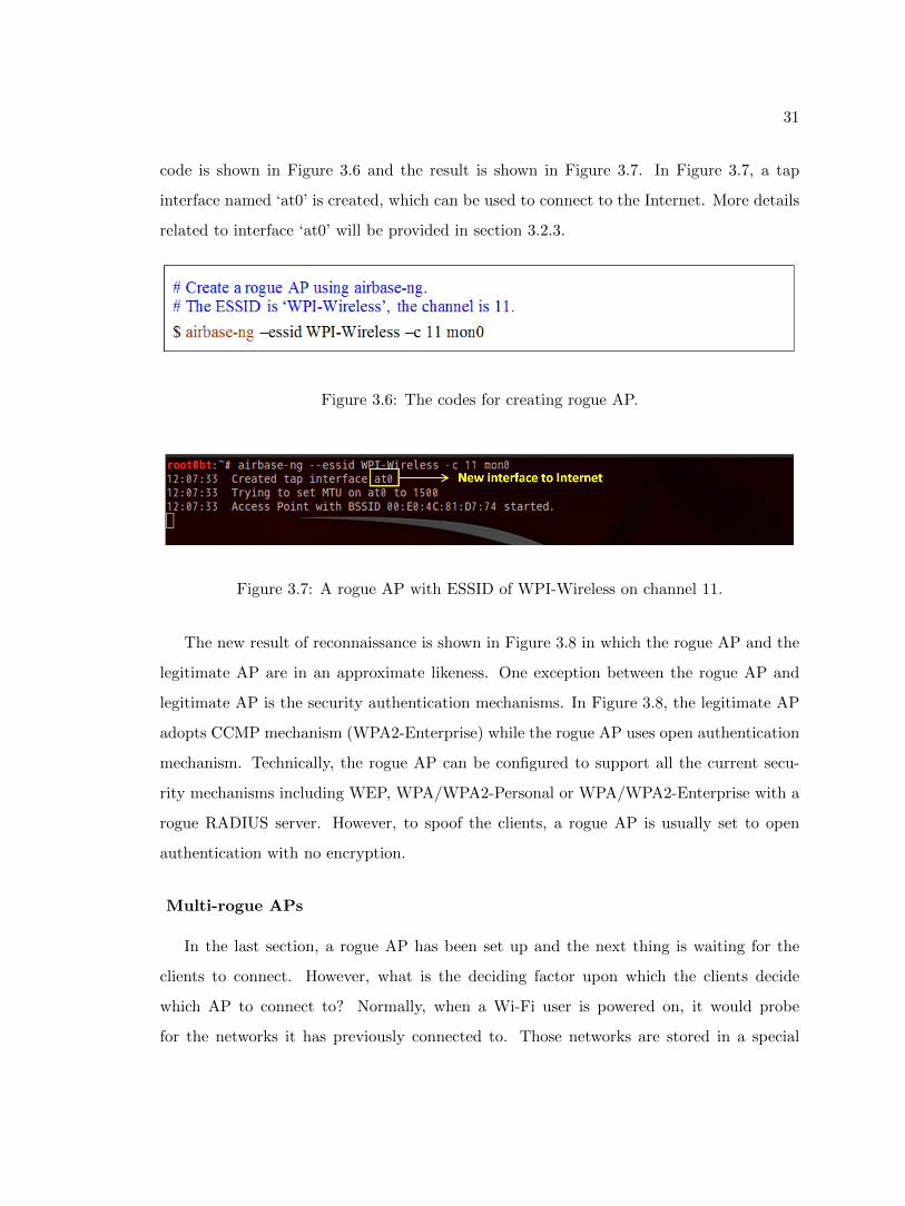
code is shown in Figure 3.6 and the result is shown in Figure 3.7. In Figure 3.7, a tap
interface named ‘at0’ is created, which can be used to connect to the Internet. More details
related to interface ‘at0’ will be provided in section 3.2.3.
Figure 3.6: The codes for creating rogue AP.
Figure 3.7: A rogue AP with ESSID of WPI-Wireless on channel 11.
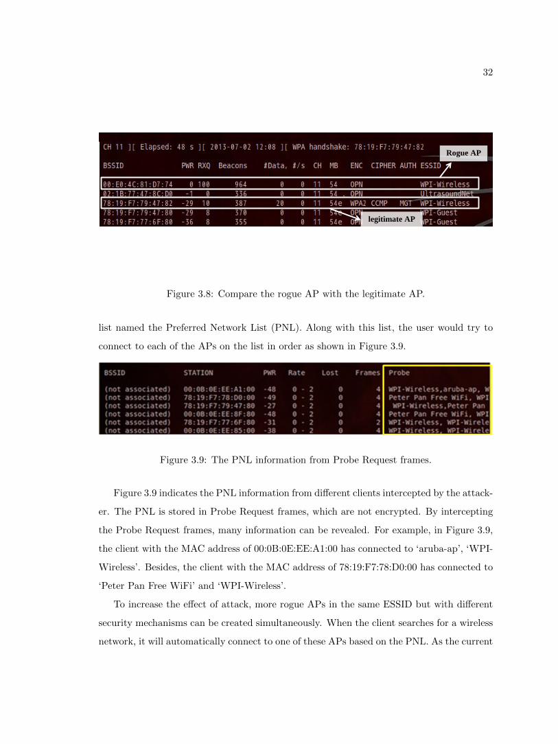
The new result of reconnaissance is shown in Figure 3.8 in which the rogue AP and the
legitimate AP are in an approximate likeness. One exception between the rogue AP and
legitimate AP is the security authentication mechanisms. In Figure 3.8, the legitimate AP
adopts CCMP mechanism (WPA2-Enterprise) while the rogue AP uses open authentication
mechanism. Technically, the rogue AP can be configured to support all the current secu-
rity mechanisms including WEP, WPA/WPA2-Personal or WPA/WPA2-Enterprise with a
rogue RADIUS server. However, to spoof the clients, a rogue AP is usually set to open
authentication with no encryption.
Multi-rogue APs
In the last section, a rogue AP has been set up and the next thing is waiting for the
clients to connect. However, what is the deciding factor upon which the clients decide
which AP to connect to? Normally, when a Wi-Fi user is powered on, it would probe
for the networks it has previously connected to. Those networks are stored in a special
32
Rogue AP
legitimate AP
Figure 3.8: Compare the rogue AP with the legitimate AP.
list named the Preferred Network List (PNL). Along with this list, the user would try to
connect to each of the APs on the list in order as shown in Figure 3.9.
Figure 3.9: The PNL information from Probe Request frames.
Figure 3.9 indicates the PNL information from different clients intercepted by the attack-
er. The PNL is stored in Probe Request frames, which are not encrypted. By intercepting
the Probe Request frames, many information can be revealed. For example, in Figure 3.9,
the client with the MAC address of 00:0B:0E:EE:A1:00 has connected to ‘aruba-ap’, ‘WPI-
Wireless’. Besides, the client with the MAC address of 78:19:F7:78:D0:00 has connected to
‘Peter Pan Free WiFi’ and ‘WPI-Wireless’.
To increase the effect of attack, more rogue APs in the same ESSID but with different
security mechanisms can be created simultaneously. When the client searches for a wireless
network, it will automatically connect to one of these APs based on the PNL. As the current
33
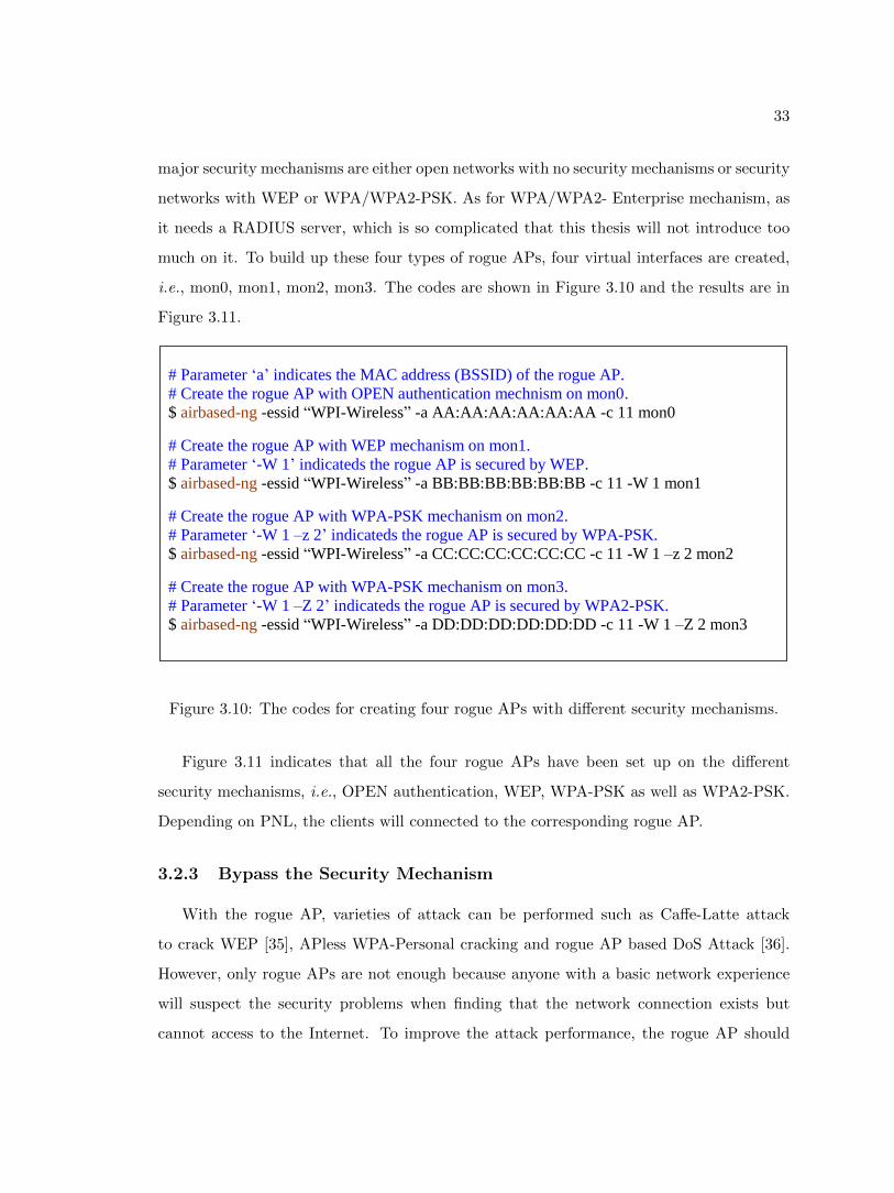
major security mechanisms are either open networks with no security mechanisms or security
networks with WEP or WPA/WPA2-PSK. As for WPA/WPA2- Enterprise mechanism, as
it needs a RADIUS server, which is so complicated that this thesis will not introduce too
much on it. To build up these four types of rogue APs, four virtual interfaces are created,
i.e., mon0, mon1, mon2, mon3. The codes are shown in Figure 3.10 and the results are in
Figure 3.11.
# Parameter ‘a’ indicates the MAC address (BSSID) of the rogue AP.
# Create the rogue AP with OPEN authentication mechnism on mon0.
$ airbased-ng -essid “WPI-Wireless” -a AA:AA:AA:AA:AA:AA -c 11 mon0
# Create the rogue AP with WEP mechanism on mon1.
# Parameter ‘-W 1’ indicateds the rogue AP is secured by WEP.
$ airbased-ng -essid “WPI-Wireless” -a BB:BB:BB:BB:BB:BB -c 11 -W 1 mon1
# Create the rogue AP with WPA-PSK mechanism on mon2.
# Parameter ‘-W 1 –z 2’ indicateds the rogue AP is secured by WPA-PSK.
$ airbased-ng -essid “WPI-Wireless” -a CC:CC:CC:CC:CC:CC -c 11 -W 1 –z 2 mon2
# Create the rogue AP with WPA-PSK mechanism on mon3.
# Parameter ‘-W 1 –Z 2’ indicateds the rogue AP is secured by WPA2-PSK.
$ airbased-ng -essid “WPI-Wireless” -a DD:DD:DD:DD:DD:DD -c 11 -W 1 –Z 2 mon3
Figure 3.10: The codes for creating four rogue APs with different security mechanisms.
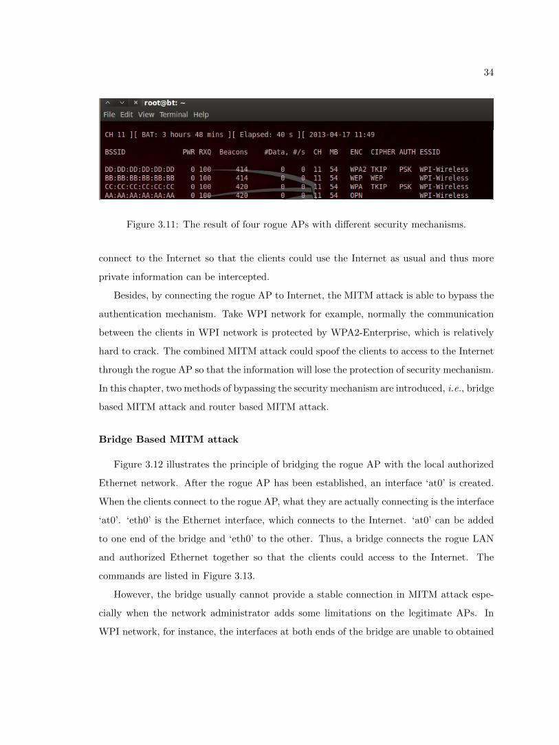
Figure 3.11 indicates that all the four rogue APs have been set up on the different
security mechanisms, i.e., OPEN authentication, WEP, WPA-PSK as well as WPA2-PSK.
Depending on PNL, the clients will connected to the corresponding rogue AP.
3.2.3 Bypass the Security Mechanism
With the rogue AP, varieties of attack can be performed such as Caffe-Latte attack
to crack WEP [35], APless WPA-Personal cracking and rogue AP based DoS Attack [36].
However, only rogue APs are not enough because anyone with a basic network experience
will suspect the security problems when finding that the network connection exists but
cannot access to the Internet. To improve the attack performance, the rogue AP should
34
Figure 3.11: The result of four rogue APs with different security mechanisms.
connect to the Internet so that the clients could use the Internet as usual and thus more
private information can be intercepted.
Besides, by connecting the rogue AP to Internet, the MITM attack is able to bypass the
authentication mechanism. Take WPI network for example, normally the communication
between the clients in WPI network is protected by WPA2-Enterprise, which is relatively
hard to crack. The combined MITM attack could spoof the clients to access to the Internet
through the rogue AP so that the information will lose the protection of security mechanism.
In this chapter, two methods of bypassing the security mechanism are introduced, i.e., bridge
based MITM attack and router based MITM attack.
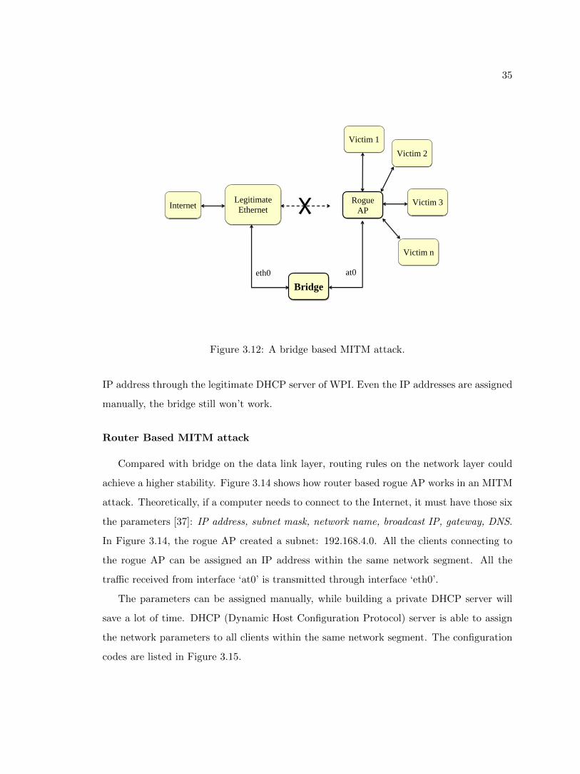
Bridge Based MITM attack
Figure 3.12 illustrates the principle of bridging the rogue AP with the local authorized
Ethernet network. After the rogue AP has been established, an interface ‘at0’ is created.
When the clients connect to the rogue AP, what they are actually connecting is the interface
‘at0’. ‘eth0’ is the Ethernet interface, which connects to the Internet. ‘at0’ can be added
to one end of the bridge and ‘eth0’ to the other. Thus, a bridge connects the rogue LAN
and authorized Ethernet together so that the clients could access to the Internet. The
commands are listed in Figure 3.13.
However, the bridge usually cannot provide a stable connection in MITM attack espe-
cially when the network administrator adds some limitations on the legitimate APs. In
WPI network, for instance, the interfaces at both ends of the bridge are unable to obtained
35
Internet Rogue
AP
Legitimate
Ethernet
Bridge
Victim 1
Victim 2
Victim 3
Victim n
eth0 at0
Figure 3.12: A bridge based MITM attack.
IP address through the legitimate DHCP server of WPI. Even the IP addresses are assigned
manually, the bridge still won’t work.
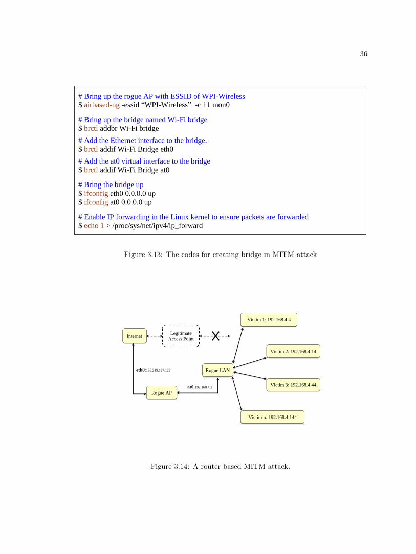
Router Based MITM attack
Compared with bridge on the data link layer, routing rules on the network layer could
achieve a higher stability. Figure 3.14 shows how router based rogue AP works in an MITM
attack. Theoretically, if a computer needs to connect to the Internet, it must have those six
the parameters [37]: IP address, subnet mask, network name, broadcast IP, gateway, DNS.
In Figure 3.14, the rogue AP created a subnet: 192.168.4.0. All the clients connecting to
the rogue AP can be assigned an IP address within the same network segment. All the
traffic received from interface ‘at0’ is transmitted through interface ‘eth0’.
The parameters can be assigned manually, while building a private DHCP server will
save a lot of time. DHCP (Dynamic Host Configuration Protocol) server is able to assign
the network parameters to all clients within the same network segment. The configuration
codes are listed in Figure 3.15.
36
# Bring up the rogue AP with ESSID of WPI-Wireless
$ airbased-ng -essid “WPI-Wireless” -c 11 mon0
# Bring up the bridge named Wi-Fi bridge
$ brctl addbr Wi-Fi bridge
# Add the Ethernet interface to the bridge.
$ brctl addif Wi-Fi Bridge eth0
# Add the at0 virtual interface to the bridge
$ brctl addif Wi-Fi Bridge at0
# Bring the bridge up
$ ifconfig eth0 0.0.0.0 up
$ ifconfig at0 0.0.0.0 up
# Enable IP forwarding in the Linux kernel to ensure packets are forwarded
$ echo 1 > /proc/sys/net/ipv4/ip_forward
Figure 3.13: The codes for creating bridge in MITM attack
Internet Legitimate
Access Point
Rogue AP
Victim 2: 192.168.4.14
Victim 1: 192.168.4.4
Rogue LAN
Victim 3: 192.168.4.44
Victim n: 192.168.4.144
eth0:130.215.127.128
at0:192.168.4.1
Figure 3.14: A router based MITM attack.
37
ddns-update-style interim;
default-lease-time 600;
max-lease-time 7200;
subnet 192.168.4.0 netmask 255.255.255.0 {
option subnet-mask 255.255.255.0;
option broadcast-address 192.168.4.255;
option routers 192.168.4.1;
option domain-name-servers 130.215.39.18;
option domain-name-servers 130.215.5.18;
range 192.168.4.2 192.168.4.150;
}
Figure 3.15: The codes for DHCP configuration.
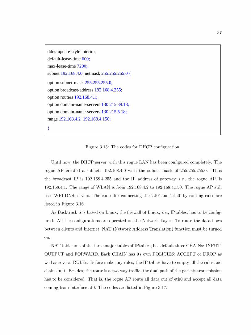
Until now, the DHCP server with this rogue LAN has been configured completely. The
rogue AP created a subnet: 192.168.4.0 with the subnet mask of 255.255.255.0. Thus
the broadcast IP is 192.168.4.255 and the IP address of gateway, i.e., the rogue AP, is
192.168.4.1. The range of WLAN is from 192.168.4.2 to 192.168.4.150. The rogue AP still
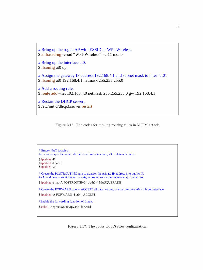
uses WPI DNS servers. The codes for connecting the ‘at0’ and ‘eth0’ by routing rules are
listed in Figure 3.16.
As Backtrack 5 is based on Linux, the firewall of Linux, i.e., IPtables, has to be config-
ured. All the configurations are operated on the Network Layer. To route the data flows
between clients and Internet, NAT (Network Address Translation) function must be turned
on.
NAT table, one of the three major tables of IPtables, has default three CHAINs: INPUT,
OUTPUT and FORWARD. Each CHAIN has its own POLICIES: ACCEPT or DROP as
well as several RULEs. Before make any rules, the IP tables have to empty all the rules and
chains in it. Besides, the route is a two-way traffic, the dual path of the packets transmission
has to be considered. That is, the rogue AP route all data out of eth0 and accept all data
coming from interface at0. The codes are listed in Figure 3.17.
38
# Bring up the rogue AP with ESSID of WPI-Wireless.
$ airbased-ng -essid “WPI-Wireless” -c 11 mon0
# Bring up the interface at0.
$ ifconfig at0 up
# Assign the gateway IP address 192.168.4.1 and subnet mask to inter `at0’.
$ ifconfig at0 192.168.4.1 netmask 255.255.255.0
# Add a routing rule.
$ route add –net 192.168.4.0 netmask 255.255.255.0 gw 192.168.4.1
# Restart the DHCP server.
$ /etc/init.d/dhcp3.server restart
Figure 3.16: The codes for making routing rules in MITM attack.
# Empty NAT iptables.
#-t: choose specific table; -F: delete all rules in chain; -X: delete all chains.
$ iptables -F
$ iptables -t nat -F
$ iptables -X
# Create the POSTROUTING rule to transfer the private IP address into public IP.
# -A: add new rules at the end of original rules; -o: output interface; -j: operations.
$ iptables -t nat -A POSTROUTING -o eth0 -j MASQUERADE
# Create the FORWARD rule to ACCEPT all data coming fromm interface at0; -I: input interface.
$ iptables -A FORWARD -I at0 -j ACCEPT
#Enable the forwarding function of Linux.
$ echo 1 > /proc/sys/net/ipv4/ip_forward
Figure 3.17: The codes for IPtables configuration.
39
Improvement on Traditional MITM attack
So far, two types of rogue APs have been introduced. Both of them belong to the
traditional MITM attack. A basic requirement for the traditional MITM attack is to connect
the wireless interface ‘at0’ with the legitimate network in advance either through wired
LANs or wireless LANs. This requirement greatly decreases the flexibility of MITM attack.
For example, an outsider who is not a WPI member will be difficult to launch the MITM
attack to WPI networks.
Therefore some improvements based on the traditional rogue APs have been made.
Nowadays, most of smart phones have a function named hot spot, which could turn the
smart phone into a wireless AP [38]. By using the hot spot function, the rogue AP could
be out of the limitations of legitimate wired/wireless LANs. Furthermore, the 4G wireless
SIM card and its adapter could also let a rogue AP access to the Internet, which makes the
rogue AP more insidious.
3.3 Kidnap the Clients
So far the rogue AP has been built up completely, the victims should be able to access
to the Internet through the rogue AP. However, what if the clients are still connecting to
the legitimate AP? How to force the clients to connect to the rogue AP?
3.3.1 The Implementation of Jamming Attacks
To solve this problem, a powerful weapon against wireless networks, DoS (Denial of
Service) attack, is adopted. DoS attack could disconnect the normal transmission between
the clients and the legitimate AP. One type of the effective DoS attacks is jamming attacks,
which can be implemented by either corrupting the operations of the MAC protocols or
transmitting large amounts of interfering wireless signals without obeying the MAC proto-
cols.
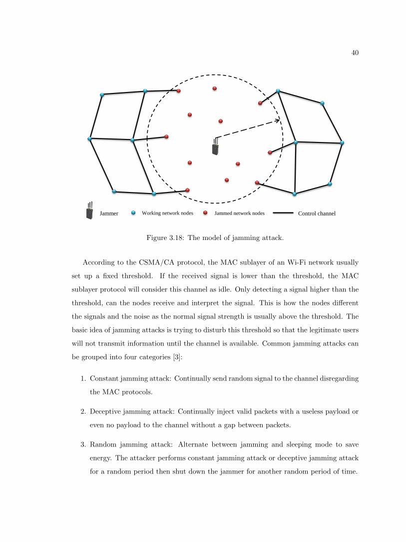
In order to better understand jamming attacks, a basic jamming attack model was set
up. In Figure 3.18, a jammer is transmitting jamming signals among the network nodes.
The communications between the nodes within the range of the jammer are corrupted.
40
Jammer Working network nodes Jammed network nodes Control channel
Figure 3.18: The model of jamming attack.
According to the CSMA/CA protocol, the MAC sublayer of an Wi-Fi network usually
set up a fixed threshold. If the received signal is lower than the threshold, the MAC
sublayer protocol will consider this channel as idle. Only detecting a signal higher than the
threshold, can the nodes receive and interpret the signal. This is how the nodes different
the signals and the noise as the normal signal strength is usually above the threshold. The
basic idea of jamming attacks is trying to disturb this threshold so that the legitimate users
will not transmit information until the channel is available. Common jamming attacks can
be grouped into four categories [3]:
1. Constant jamming attack: Continually send random signal to the channel disregarding
the MAC protocols.
2. Deceptive jamming attack: Continually inject valid packets with a useless payload or
even no payload to the channel without a gap between packets.
3. Random jamming attack: Alternate between jamming and sleeping mode to save
energy. The attacker performs constant jamming attack or deceptive jamming attack
for a random period then shut down the jammer for another random period of time.
41
4. Reactive jamming attack: Stay quiet and keep sensing the channel until there is a com-
munication in the channel then corrupted transmission signal using only a minimum
amount of power, which brings more imperceptibility.
To evaluate the efficiency of each jamming attacks, two metrics were proposed:
1. Packets Send Ratio:
Packets Send Ratio (PSR) is the ratio of the number of frames that are actually sent
into the channel compared to frames that are intended to be sent into the channel.
For instance, node A intends to send Y frames to node B however only X of Y are
send out for some reason. Then
PSR =X
Y(3.1)
Equation 3.1 is used to calculate the PSR by the transmitter and the PSR value can
be only calculated by the transmitter.
2. Packets Delivery Ratio:
Packets Delivery Ratio (PDR) is the ratio of the of the number of frames which the
receiver receives successfully compared to the number of frames that have been sent
out from the sender. In the above instance, X frames were actually sent into the
channel, if Z frames were received by B successfully, then
PDR =Z
X(3.2)
Equation 3.2 is used to calculate the PDR by the receiver end. However, unlike the
PSR which can be only calculated by the transmitter end, the PDR can be calculated
at both transmitter and receiver ends.
So, how could the receiver end calculate the exact number of frames which are suc-
cessfully received by the receiver? Consider Figure 2.6, according to the protocol if a
frame is received by receiver successfully, the receiver will return an ACK frame. In
42
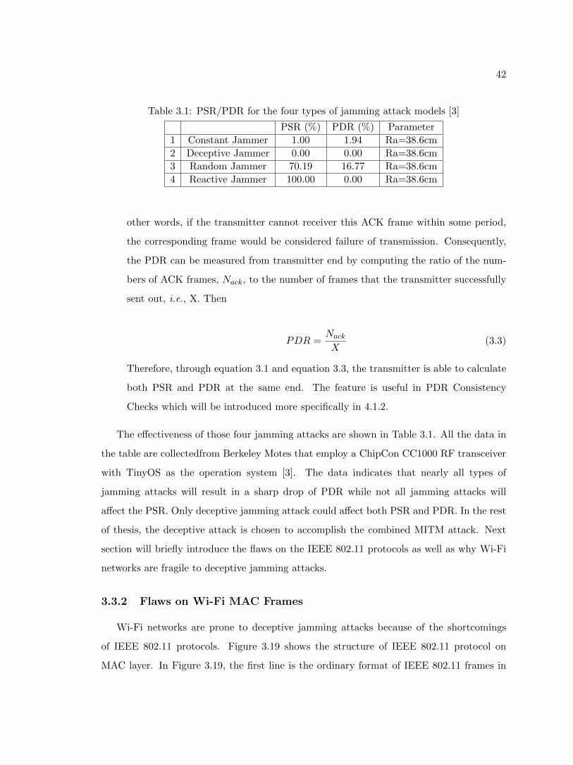
Table 3.1: PSR/PDR for the four types of jamming attack models [3]
PSR (%) PDR (%) Parameter
1 Constant Jammer 1.00 1.94 Ra=38.6cm
2 Deceptive Jammer 0.00 0.00 Ra=38.6cm
3 Random Jammer 70.19 16.77 Ra=38.6cm
4 Reactive Jammer 100.00 0.00 Ra=38.6cm
other words, if the transmitter cannot receiver this ACK frame within some period,
the corresponding frame would be considered failure of transmission. Consequently,
the PDR can be measured from transmitter end by computing the ratio of the num-
bers of ACK frames, Nack, to the number of frames that the transmitter successfully
sent out, i.e., X. Then
PDR =Nack
X(3.3)
Therefore, through equation 3.1 and equation 3.3, the transmitter is able to calculate
both PSR and PDR at the same end. The feature is useful in PDR Consistency
Checks which will be introduced more specifically in 4.1.2.
The effectiveness of those four jamming attacks are shown in Table 3.1. All the data in
the table are collectedfrom Berkeley Motes that employ a ChipCon CC1000 RF transceiver
with TinyOS as the operation system [3]. The data indicates that nearly all types of
jamming attacks will result in a sharp drop of PDR while not all jamming attacks will
affect the PSR. Only deceptive jamming attack could affect both PSR and PDR. In the rest
of thesis, the deceptive attack is chosen to accomplish the combined MITM attack. Next
section will briefly introduce the flaws on the IEEE 802.11 protocols as well as why Wi-Fi
networks are fragile to deceptive jamming attacks.
3.3.2 Flaws on Wi-Fi MAC Frames
Wi-Fi networks are prone to deceptive jamming attacks because of the shortcomings
of IEEE 802.11 protocols. Figure 3.19 shows the structure of IEEE 802.11 protocol on
MAC layer. In Figure 3.19, the first line is the ordinary format of IEEE 802.11 frames in
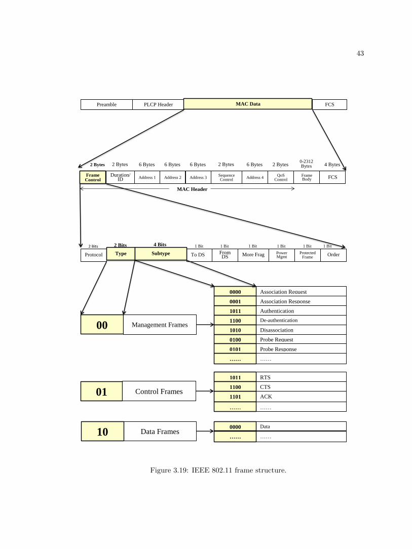
43
PLCP Header Preamble FCS MAC Data
Protocol To DS From DS More Frag Power
Mgmt Protected
Frame Order Type Subtype
2 Bits 1 Bit 1 Bit 1 Bit 1 Bit 1 Bit 1 Bit 2 Bits 4 Bits
2 Bytes 6 Bytes 6 Bytes 6 Bytes 2 Bytes 6 Bytes 2 Bytes 0-2312 Bytes 4 Bytes 2 Bytes
Duration/ID Address 1 Address 2 Address 3
Sequence Control
Address 4 QoS
Control Frame Body FCS Frame
Control
MAC Header
Authentication 1011
Association Request 0000
Association Response 0001
De-authentication 1100
Probe Request 0100
…… ……
Probe Response 0101
Disassociation 1010
RTS 1011
ACK 1101
CTS 1100
…… ……
Data 0000
…… ……
00 Management Frames
01 Control Frames
10 Data Frames
Figure 3.19: IEEE 802.11 frame structure.
44
MAC sublayer. The critical piece of the frame is the ‘MAC data’ which can be extended to
the second layer. The 2-byte ‘Frame Control’ determines the type of frames. The ‘Frame
Control’ section spread to the third layer, in which the 2-bit ‘Type’ section divides the MAC
frames into three types [28].
1. Management frames:
Management frames are responsible for maintaining communication between the AP
and wireless clients. The Management frames can be divided into many sub-types
(decided by the 4-bit ‘Subtype‘ section). Figure 3.19 only indicates the following im-
portant ones: Authentication, De-Authentication, Association Request, Association
Response, Disassociation, Probe Request, Probe Response. Those sub-types are re-
sponsible for the initial interactive operations between the clients and APs. More
details related to the sub-types frames are provided in section ”How does a client
connect to an existing AP? ”
2. Control Frames:
Control frames are in charge of ensuring a proper exchange of data between the AP
and wireless clients. Control frames have three sub-types: CTS, RTS, ACK. Control
frames are used for CSMA/CA mechanism. More details have been introduced in
Section 2.2.2.
3. Data frames:
Data frames contain the actual data received from network layer and they are pro-
tected by the security mechanisms such as WEP, WPA or WPA2.
The key point is that only Data frames are encrypted, Management frames and Control
frames are not encrypted. This brings two hidden troubles. The first one is the unencrypted
Management frames may disclose private information. As it did in the case of revealing Wi-
Fi information in the Reconnaissance section. The hidden ESSID, for instance, can be
revealed from Probe frames, which belong to Management frames. The second trouble
is that the attackers can perform deceptive jamming attacks by transmitting forged De-
authentication Frames.
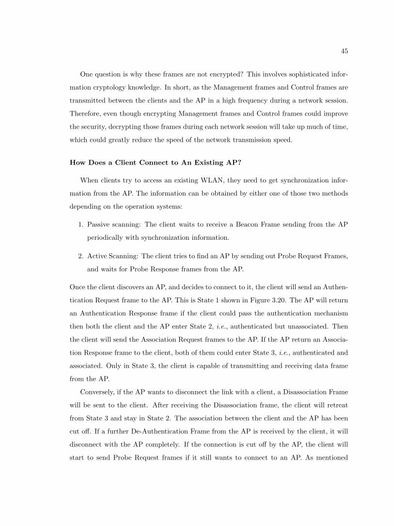
45
One question is why these frames are not encrypted? This involves sophisticated infor-
mation cryptology knowledge. In short, as the Management frames and Control frames are
transmitted between the clients and the AP in a high frequency during a network session.
Therefore, even though encrypting Management frames and Control frames could improve
the security, decrypting those frames during each network session will take up much of time,
which could greatly reduce the speed of the network transmission speed.
How Does a Client Connect to An Existing AP?
When clients try to access an existing WLAN, they need to get synchronization infor-
mation from the AP. The information can be obtained by either one of those two methods
depending on the operation systems:
1. Passive scanning: The client waits to receive a Beacon Frame sending from the AP
periodically with synchronization information.
2. Active Scanning: The client tries to find an AP by sending out Probe Request Frames,
and waits for Probe Response frames from the AP.
Once the client discovers an AP, and decides to connect to it, the client will send an Authen-
tication Request frame to the AP. This is State 1 shown in Figure 3.20. The AP will return
an Authentication Response frame if the client could pass the authentication mechanism
then both the client and the AP enter State 2, i.e., authenticated but unassociated. Then
the client will send the Association Request frames to the AP. If the AP return an Associa-
tion Response frame to the client, both of them could enter State 3, i.e., authenticated and
associated. Only in State 3, the client is capable of transmitting and receiving data frame
from the AP.
Conversely, if the AP wants to disconnect the link with a client, a Disassociation Frame
will be sent to the client. After receiving the Disassociation frame, the client will retreat
from State 3 and stay in State 2. The association between the client and the AP has been
cut off. If a further De-Authentication Frame from the AP is received by the client, it will
disconnect with the AP completely. If the connection is cut off by the AP, the client will
start to send Probe Request frames if it still wants to connect to an AP. As mentioned
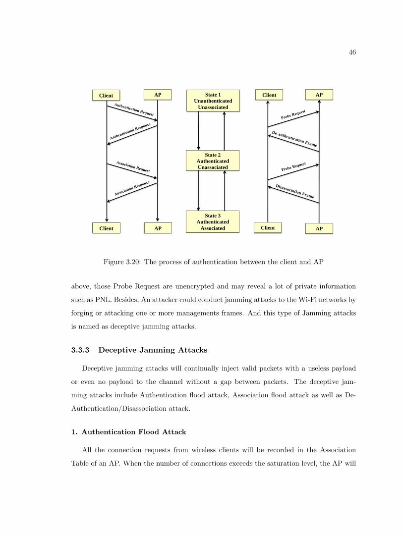
46
AP State 1
Unauthenticated
Unassociated
State 2
Authenticated
Unassociated
State 3
Authenticated
Associated
Client
AP Client
AP Client
Client AP
Figure 3.20: The process of authentication between the client and AP
above, those Probe Request are unencrypted and may reveal a lot of private information
such as PNL. Besides, An attacker could conduct jamming attacks to the Wi-Fi networks by
forging or attacking one or more managements frames. And this type of Jamming attacks
is named as deceptive jamming attacks.
3.3.3 Deceptive Jamming Attacks
Deceptive jamming attacks will continually inject valid packets with a useless payload
or even no payload to the channel without a gap between packets. The deceptive jam-
ming attacks include Authentication flood attack, Association flood attack as well as De-
Authentication/Disassociation attack.
1. Authentication Flood Attack
All the connection requests from wireless clients will be recorded in the Association
Table of an AP. When the number of connections exceeds the saturation level, the AP will
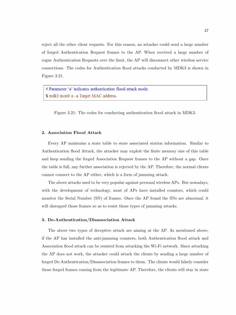
47
reject all the other client requests. For this reason, an attacker could send a large number
of forged Authentication Request frames to the AP. When received a large number of
rogue Authentication Requests over the limit, the AP will disconnect other wireless service
connections. The codes for Authentication flood attacks conducted by MDK3 is shown in
Figure 3.21.
Figure 3.21: The codes for conducting authentication flood attack in MDK3.
2. Association Flood Attack
Every AP maintains a state table to store associated station information. Similar to
Authentication flood Attack, the attacker may exploit the finite memory size of this table
and keep sending the forged Association Request frames to the AP without a gap. Once
the table is full, any further association is rejected by the AP. Therefore, the normal clients
cannot connect to the AP either, which is a form of jamming attack.
The above attacks used to be very popular against personal wireless APs. But nowadays,
with the development of technology, most of APs have installed counters, which could
monitor the Serial Number (SN) of frames. Once the AP found the SNs are abnormal, it
will disregard those frames so as to resist those types of jamming attacks.
3. De-Authentication/Disassociation Attack
The above two types of deceptive attack are aiming at the AP. As mentioned above,
if the AP has installed the anti-jamming counters, both Authentication flood attack and
Association flood attack can be resisted from attacking the Wi-Fi network. Since attacking
the AP does not work, the attacker could attack the clients by sending a large number of
forged De-Authentication/Disassociation frames to them. The clients would falsely consider
those forged frames coming from the legitimate AP. Therefore, the clients will stay in state
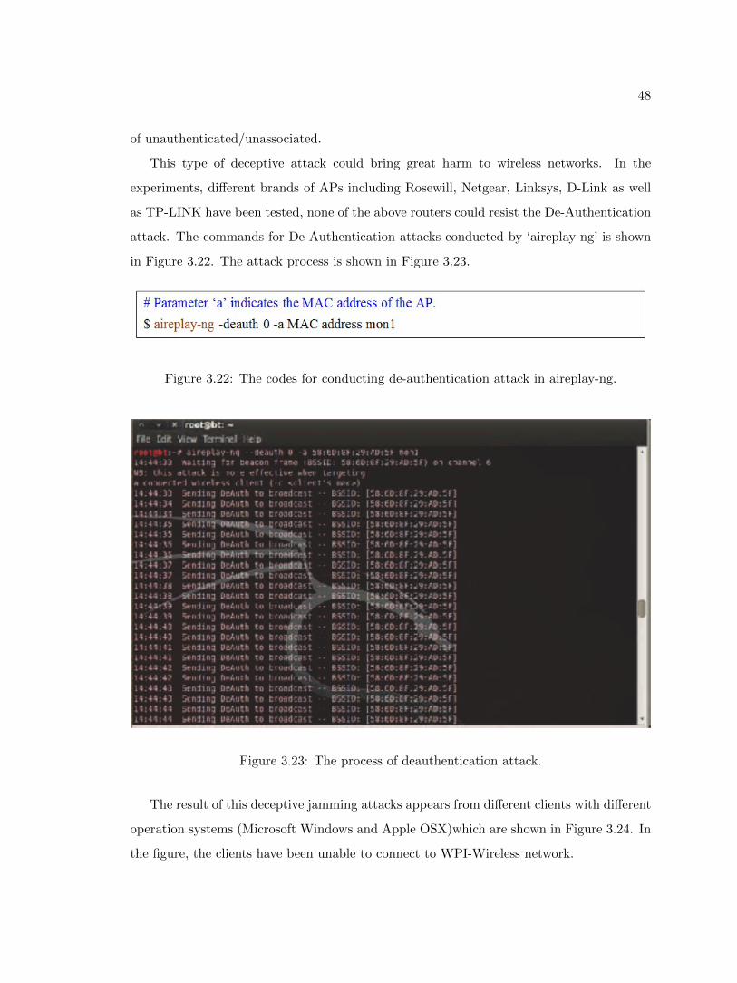
48
of unauthenticated/unassociated.
This type of deceptive attack could bring great harm to wireless networks. In the
experiments, different brands of APs including Rosewill, Netgear, Linksys, D-Link as well
as TP-LINK have been tested, none of the above routers could resist the De-Authentication
attack. The commands for De-Authentication attacks conducted by ‘aireplay-ng’ is shown
in Figure 3.22. The attack process is shown in Figure 3.23.
Figure 3.22: The codes for conducting de-authentication attack in aireplay-ng.
Figure 3.23: The process of deauthentication attack.
The result of this deceptive jamming attacks appears from different clients with different
operation systems (Microsoft Windows and Apple OSX)which are shown in Figure 3.24. In
the figure, the clients have been unable to connect to WPI-Wireless network.
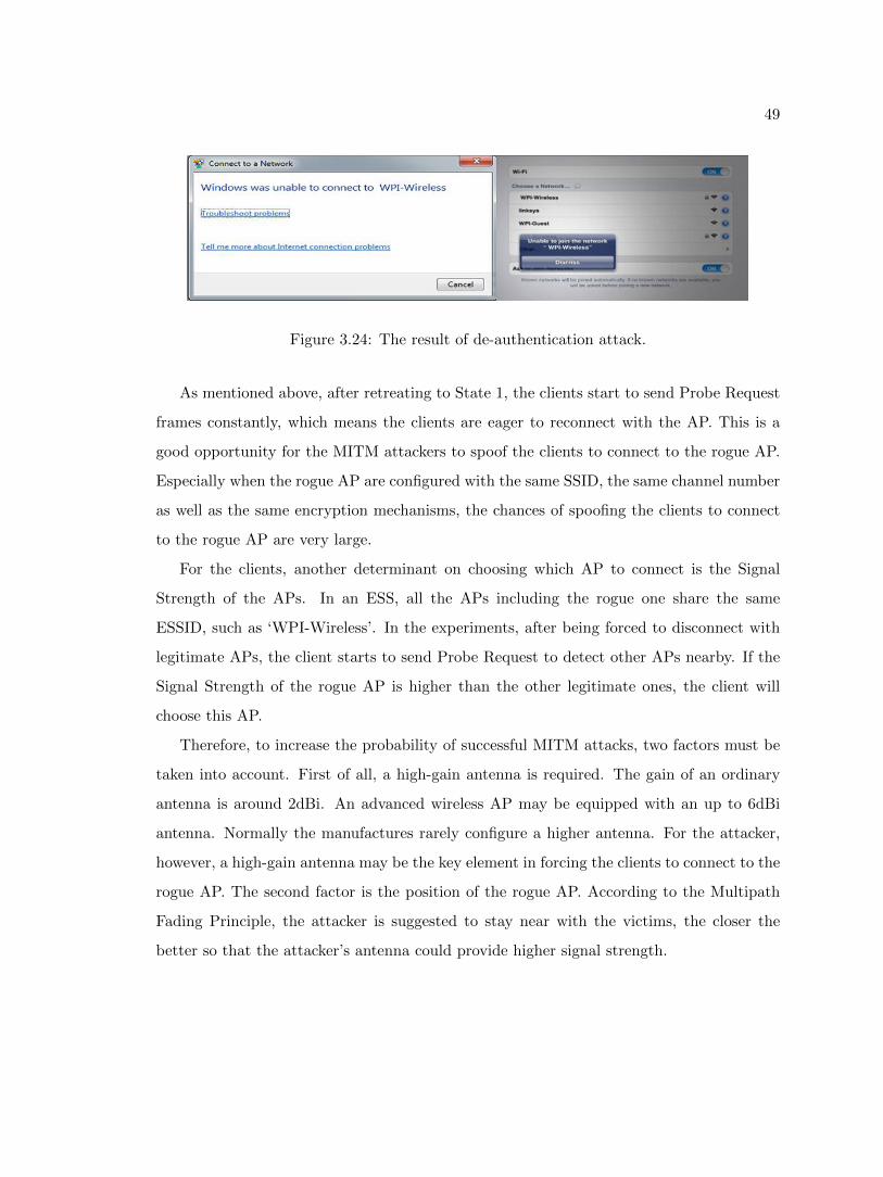
49
Figure 3.24: The result of de-authentication attack.
As mentioned above, after retreating to State 1, the clients start to send Probe Request
frames constantly, which means the clients are eager to reconnect with the AP. This is a
good opportunity for the MITM attackers to spoof the clients to connect to the rogue AP.
Especially when the rogue AP are configured with the same SSID, the same channel number
as well as the same encryption mechanisms, the chances of spoofing the clients to connect
to the rogue AP are very large.
For the clients, another determinant on choosing which AP to connect is the Signal
Strength of the APs. In an ESS, all the APs including the rogue one share the same
ESSID, such as ‘WPI-Wireless’. In the experiments, after being forced to disconnect with
legitimate APs, the client starts to send Probe Request to detect other APs nearby. If the
Signal Strength of the rogue AP is higher than the other legitimate ones, the client will
choose this AP.
Therefore, to increase the probability of successful MITM attacks, two factors must be
taken into account. First of all, a high-gain antenna is required. The gain of an ordinary
antenna is around 2dBi. An advanced wireless AP may be equipped with an up to 6dBi
antenna. Normally the manufactures rarely configure a higher antenna. For the attacker,
however, a high-gain antenna may be the key element in forcing the clients to connect to the
rogue AP. The second factor is the position of the rogue AP. According to the Multipath
Fading Principle, the attacker is suggested to stay near with the victims, the closer the
better so that the attacker’s antenna could provide higher signal strength.
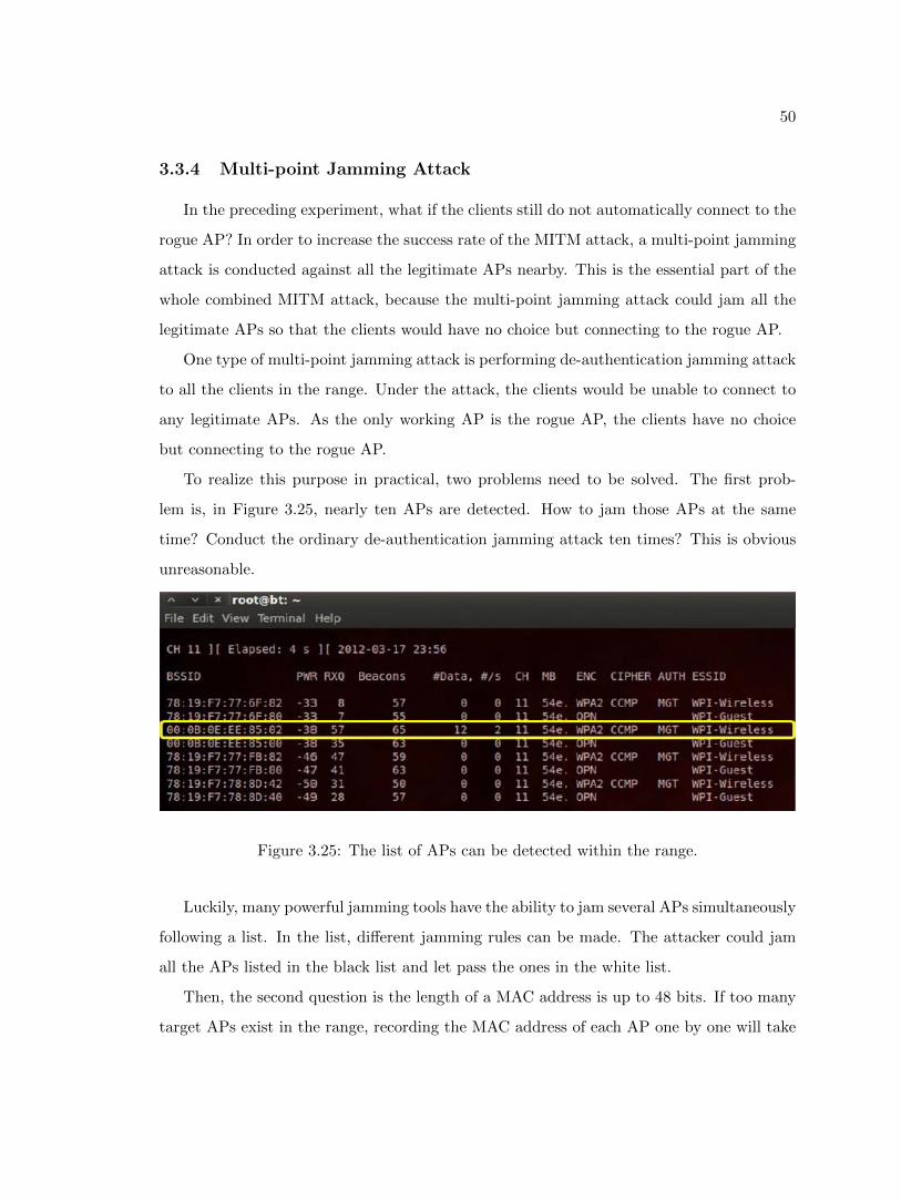
50
3.3.4 Multi-point Jamming Attack
In the preceding experiment, what if the clients still do not automatically connect to the
rogue AP? In order to increase the success rate of the MITM attack, a multi-point jamming
attack is conducted against all the legitimate APs nearby. This is the essential part of the
whole combined MITM attack, because the multi-point jamming attack could jam all the
legitimate APs so that the clients would have no choice but connecting to the rogue AP.
One type of multi-point jamming attack is performing de-authentication jamming attack
to all the clients in the range. Under the attack, the clients would be unable to connect to
any legitimate APs. As the only working AP is the rogue AP, the clients have no choice
but connecting to the rogue AP.
To realize this purpose in practical, two problems need to be solved. The first prob-
lem is, in Figure 3.25, nearly ten APs are detected. How to jam those APs at the same
time? Conduct the ordinary de-authentication jamming attack ten times? This is obvious
unreasonable.
Figure 3.25: The list of APs can be detected within the range.
Luckily, many powerful jamming tools have the ability to jam several APs simultaneously
following a list. In the list, different jamming rules can be made. The attacker could jam
all the APs listed in the black list and let pass the ones in the white list.
Then, the second question is the length of a MAC address is up to 48 bits. If too many
target APs exist in the range, recording the MAC address of each AP one by one will take
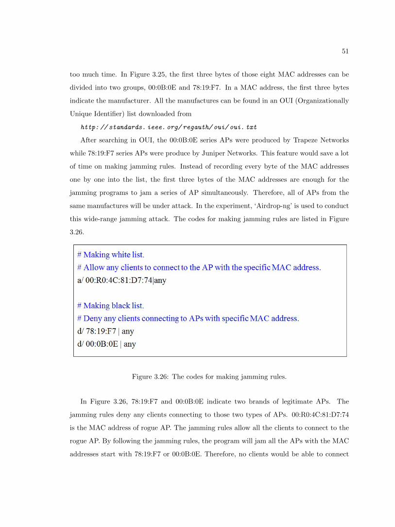
51
too much time. In Figure 3.25, the first three bytes of those eight MAC addresses can be
divided into two groups, 00:0B:0E and 78:19:F7. In a MAC address, the first three bytes
indicate the manufacturer. All the manufactures can be found in an OUI (Organizationally
Unique Identifier) list downloaded from
http: // standards. ieee. org/ regauth/ oui/ oui. txt
After searching in OUI, the 00:0B:0E series APs were produced by Trapeze Networks
while 78:19:F7 series APs were produce by Juniper Networks. This feature would save a lot
of time on making jamming rules. Instead of recording every byte of the MAC addresses
one by one into the list, the first three bytes of the MAC addresses are enough for the
jamming programs to jam a series of AP simultaneously. Therefore, all of APs from the
same manufactures will be under attack. In the experiment, ‘Airdrop-ng’ is used to conduct
this wide-range jamming attack. The codes for making jamming rules are listed in Figure
3.26.
Figure 3.26: The codes for making jamming rules.
In Figure 3.26, 78:19:F7 and 00:0B:0E indicate two brands of legitimate APs. The
jamming rules deny any clients connecting to those two types of APs. 00:R0:4C:81:D7:74
is the MAC address of rogue AP. The jamming rules allow all the clients to connect to the
rogue AP. By following the jamming rules, the program will jam all the APs with the MAC
addresses start with 78:19:F7 or 00:0B:0E. Therefore, no clients would be able to connect
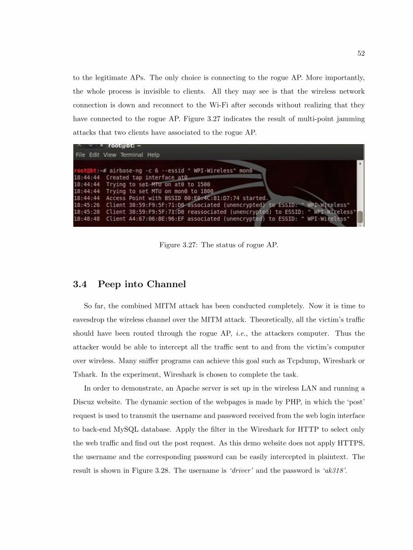
52
to the legitimate APs. The only choice is connecting to the rogue AP. More importantly,
the whole process is invisible to clients. All they may see is that the wireless network
connection is down and reconnect to the Wi-Fi after seconds without realizing that they
have connected to the rogue AP. Figure 3.27 indicates the result of multi-point jamming
attacks that two clients have associated to the rogue AP.
Figure 3.27: The status of rogue AP.
3.4 Peep into Channel
So far, the combined MITM attack has been conducted completely. Now it is time to
eavesdrop the wireless channel over the MITM attack. Theoretically, all the victim’s traffic
should have been routed through the rogue AP, i.e., the attackers computer. Thus the
attacker would be able to intercept all the traffic sent to and from the victim’s computer
over wireless. Many sniffer programs can achieve this goal such as Tcpdump, Wireshark or
Tshark. In the experiment, Wireshark is chosen to complete the task.
In order to demonstrate, an Apache server is set up in the wireless LAN and running a
Discuz website. The dynamic section of the webpages is made by PHP, in which the ‘post’
request is used to transmit the username and password received from the web login interface
to back-end MySQL database. Apply the filter in the Wireshark for HTTP to select only
the web traffic and find out the post request. As this demo website does not apply HTTPS,
the username and the corresponding password can be easily intercepted in plaintext. The
result is shown in Figure 3.28. The username is ‘driver’ and the password is ‘ak318’.
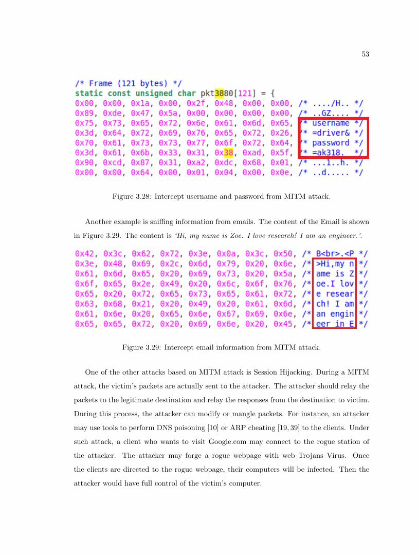
53
Figure 3.28: Intercept username and password from MITM attack.
Another example is sniffing information from emails. The content of the Email is shown
in Figure 3.29. The content is ‘Hi, my name is Zoe. I love research! I am an engineer.’.
Figure 3.29: Intercept email information from MITM attack.
One of the other attacks based on MITM attack is Session Hijacking. During a MITM
attack, the victim’s packets are actually sent to the attacker. The attacker should relay the
packets to the legitimate destination and relay the responses from the destination to victim.
During this process, the attacker can modify or mangle packets. For instance, an attacker
may use tools to perform DNS poisoning [10] or ARP cheating [19, 39] to the clients. Under
such attack, a client who wants to visit Google.com may connect to the rogue station of
the attacker. The attacker may forge a rogue webpage with web Trojans Virus. Once
the clients are directed to the rogue webpage, their computers will be infected. Then the
attacker would have full control of the victim’s computer.
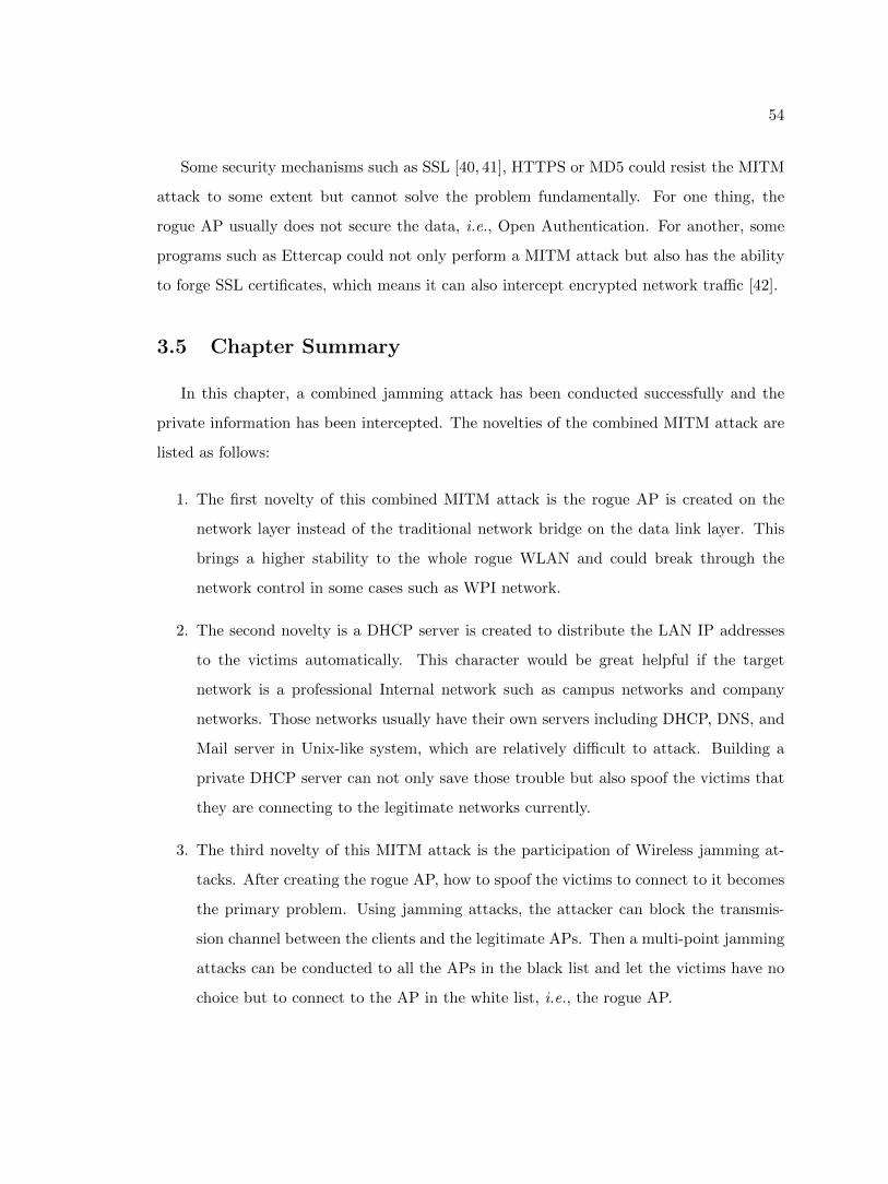
54
Some security mechanisms such as SSL [40, 41], HTTPS or MD5 could resist the MITM
attack to some extent but cannot solve the problem fundamentally. For one thing, the
rogue AP usually does not secure the data, i.e., Open Authentication. For another, some
programs such as Ettercap could not only perform a MITM attack but also has the ability
to forge SSL certificates, which means it can also intercept encrypted network traffic [42].
3.5 Chapter Summary
In this chapter, a combined jamming attack has been conducted successfully and the
private information has been intercepted. The novelties of the combined MITM attack are
listed as follows:
1. The first novelty of this combined MITM attack is the rogue AP is created on the
network layer instead of the traditional network bridge on the data link layer. This
brings a higher stability to the whole rogue WLAN and could break through the
network control in some cases such as WPI network.
2. The second novelty is a DHCP server is created to distribute the LAN IP addresses
to the victims automatically. This character would be great helpful if the target
network is a professional Internal network such as campus networks and company
networks. Those networks usually have their own servers including DHCP, DNS, and
Mail server in Unix-like system, which are relatively difficult to attack. Building a
private DHCP server can not only save those trouble but also spoof the victims that
they are connecting to the legitimate networks currently.
3. The third novelty of this MITM attack is the participation of Wireless jamming at-
tacks. After creating the rogue AP, how to spoof the victims to connect to it becomes
the primary problem. Using jamming attacks, the attacker can block the transmis-
sion channel between the clients and the legitimate APs. Then a multi-point jamming
attacks can be conducted to all the APs in the black list and let the victims have no
choice but to connect to the AP in the white list, i.e., the rogue AP.
55
Among so many jamming attacks, deceptive jamming attack is chosen for the reason
that its performance is better on dropping both PDR and PSR down to 0%. The deceptive
jamming attack is effective because the Management Frames are not encrypted. This is
the flaw deeply rooted in the Wi-Fi protocols, many wireless APs with the value of ranging
from $20 to $200 cannot resist this type of jamming attacks.
Even though many good ideas are mentioned to resist MITM attack, few wireless devices
in practice could achieve this. Unencrypted Managements frames are the basic reason but
they cannot be encrypted because the more encryption mechanisms are applied, the more
time are needed to decrypt the frames. Accordingly, the entire wireless network efficiency
will be greatly affected.
One thing needs to be mentioned is that MITM attacks come in many forms. This thesis
introduces two types of rogue APs, two ways to bypass the security mechanisms as well as
several types of jamming attacks. By combining those varieties, the MITM attacks can be
derived into many forms. Due to space limitations, only one representative MITM attack,
the combined MITM attack, is chosen. As the multi-point jamming attacks can achieve
a better performance on spoofing the clients to connect to the rogue AP, this combined
MITM does not change the BSSID of rogue AP. Therefore the multi-point jamming attacks
would be able to jam all the legitimate APs and let go the rogue one. Furthermore, as the
combined MITM uses a ‘hot spot’ to connect to the internet, the IDS or IPS system of
the organization cannot detect the rogue AP. According to the experiments, the combined
MITM attack has a higher success rate and concealment compared with the traditional
MITM attack.
In the rest of this thesis, an RSSI based MITM attack detection mechanism will be
introduced. As the attack combined two major parts, the jamming attack and the rogue
AP attack, correspondingly the detection mechanism is divided into two segments. The
first segment dedicates to differentiate different types of jamming attacks. Then the RSSI
based mechanism could detect rogue AP.
56
Chapter 4
The Detection of
Man-In-The-Middle Attack
4.1 The Detection of Jamming Attacks
In this section, a combined detection mechanism is proposed to distinguish different
types of jamming attacks against wireless networks. Many jamming detection approaches
[20, 24, 43] cannot provide a precise way for differentiating between the various categories
of jamming attacks. To enable the network to perform defense strategies more effectively,
distinguishing the type of different jamming attacks is necessary.
We improved one of the existing jamming detection approaches, Signal Strength Con-
sistency Checks, and combined a new mechanism named PDR Consistency Checks with it.
The PDR Consistency Checks is based on the statistical data of Packets Send Ratio (PSR)
and Packets Delivery Ratio (PDR) in different jamming situations. This combined detec-
tion mechanism can not only detect the existence of jamming attacks but also differentiate
the types of jamming attacks.
To explain the principle more explicitly, we divided the whole process into two proce-
dures. First, we compare the correlation between the Signal Strength (SS) and PDR in
order to determine whether a jamming attack exists. Then based on the statistical relation-
ship between PSR and PDR in different jamming situations, we further divide the type of
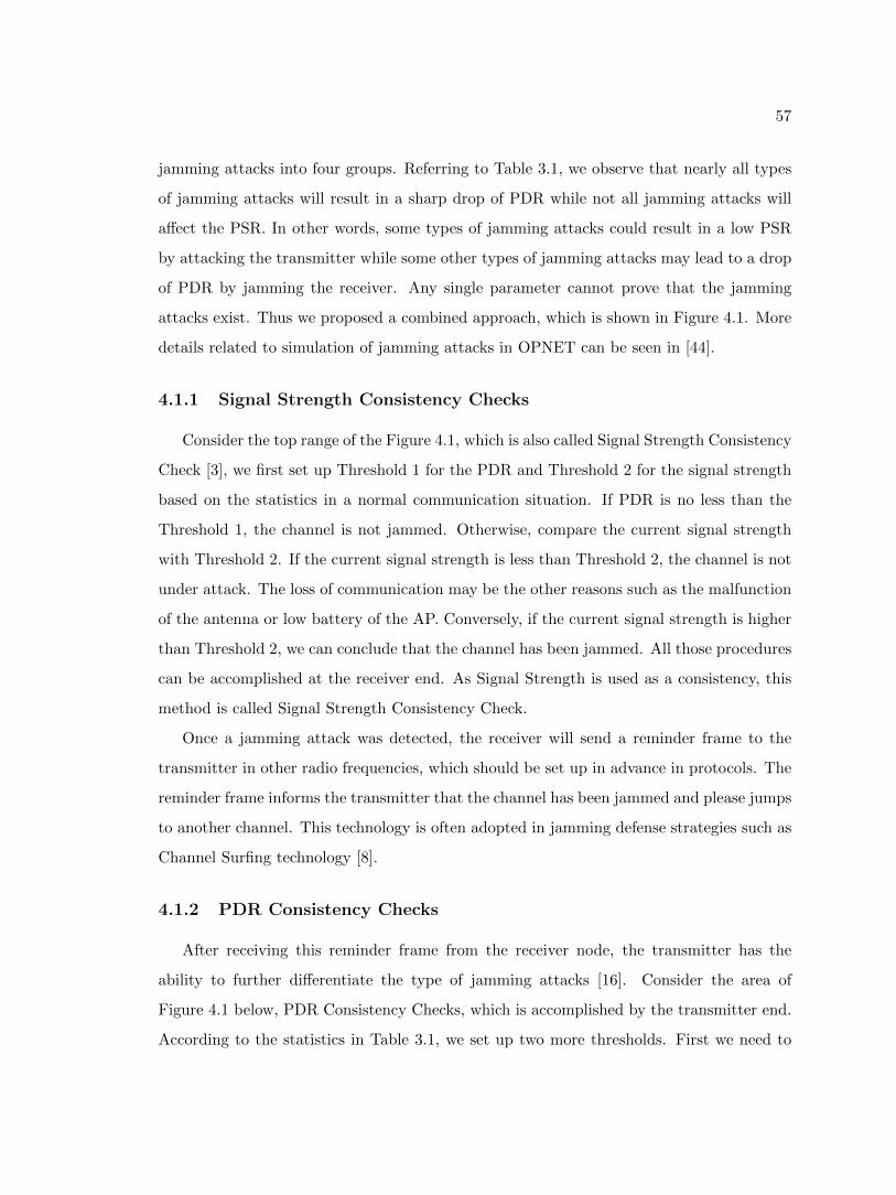
57
jamming attacks into four groups. Referring to Table 3.1, we observe that nearly all types
of jamming attacks will result in a sharp drop of PDR while not all jamming attacks will
affect the PSR. In other words, some types of jamming attacks could result in a low PSR
by attacking the transmitter while some other types of jamming attacks may lead to a drop
of PDR by jamming the receiver. Any single parameter cannot prove that the jamming
attacks exist. Thus we proposed a combined approach, which is shown in Figure 4.1. More
details related to simulation of jamming attacks in OPNET can be seen in [44].
4.1.1 Signal Strength Consistency Checks
Consider the top range of the Figure 4.1, which is also called Signal Strength Consistency
Check [3], we first set up Threshold 1 for the PDR and Threshold 2 for the signal strength
based on the statistics in a normal communication situation. If PDR is no less than the
Threshold 1, the channel is not jammed. Otherwise, compare the current signal strength
with Threshold 2. If the current signal strength is less than Threshold 2, the channel is not
under attack. The loss of communication may be the other reasons such as the malfunction
of the antenna or low battery of the AP. Conversely, if the current signal strength is higher
than Threshold 2, we can conclude that the channel has been jammed. All those procedures
can be accomplished at the receiver end. As Signal Strength is used as a consistency, this
method is called Signal Strength Consistency Check.
Once a jamming attack was detected, the receiver will send a reminder frame to the
transmitter in other radio frequencies, which should be set up in advance in protocols. The
reminder frame informs the transmitter that the channel has been jammed and please jumps
to another channel. This technology is often adopted in jamming defense strategies such as
Channel Surfing technology [8].
4.1.2 PDR Consistency Checks
After receiving this reminder frame from the receiver node, the transmitter has the
ability to further differentiate the type of jamming attacks [16]. Consider the area of
Figure 4.1 below, PDR Consistency Checks, which is accomplished by the transmitter end.
According to the statistics in Table 3.1, we set up two more thresholds. First we need to
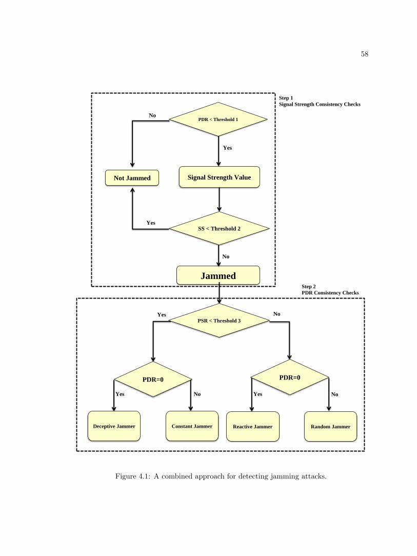
58
No
Yes
No
Yes
Signal Strength Value
PDR < Threshold 1
Not Jammed
Jammed
SS < Threshold 2
Yes
Yes
Yes
Deceptive Jammer
PDR=0
Constant Jammer Reactive Jammer Random Jammer
PDR=0
PSR < Threshold 3
No
No No
Step 1
Signal Strength Consistency Checks
Step 2
PDR Consistency Checks
Figure 4.1: A combined approach for detecting jamming attacks.
59
calculate PSR at the transmitter and compare it with threshold 3. Based on the result,
we could further divide the jamming attacks into two groups, Constant Jammer/Deceptive
Jammer group and Random Jammer/Reactive Jammer group.
For the first group, as the transmitter keeps staying in receiving/sensing mode, no
ordinary communication would exist in the channel. Therefore the PDR will be 0%. For
the second group, as the reactive jamming attack aims at the receiver, the PSR will not
be affected, but the PSR would be kept around 0%. By comparing the value of PSR
with different threshold, the transmitter would be able to differentiate the type of jamming
attacks easily.
As described in the above section, the value of PSR can be calculated only at the
transmitter end because only the transmitter can record how many data packets it is going
to send into the channel. While the value of PDR can be calculated at both ends of the
channel. The receiver could calculate the value of PDR by computing the ratio of the
number of frames received correctly by the receiver compared to the numbers of frames
that were sent into the channel. Besides, the transmitter could also calculate the value of
PDR by computing the ratio of the numbers of ACK frames sent back from the receiver to
the number of frames that the transmitter successfully sent out. Therefore the transmitter
calculates both PDR and PSR values and use the value of PDR as the consistency.
The algorithm of PDR Consistency Checks is listed as follows. In this algorithm, two
variables, MaxPSR and MinPDR, have to be measured simultaneously at the transmitting
node. If MaxPSR is less than PSRThresh 3, which should be set up in advance, the
type of jamming attack may be Deceptive jamming attacks or Constant jamming attacks.
Otherwise the result may be either Reactive jamming attacks or Random jamming attacks.
By comparing the minimum value of PDR with 0%, those four kinds of jamming attacks
can be distinguished explicitly.
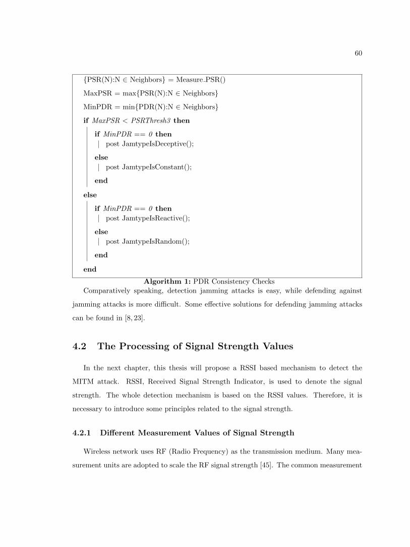
60
{PSR(N):N ∈ Neighbors} = Measure PSR()
MaxPSR = max{PSR(N):N ∈ Neighbors}
MinPDR = min{PDR(N):N ∈ Neighbors}
if MaxPSR < PSRThresh3 then
if MinPDR == 0 then
post JamtypeIsDeceptive();
else
post JamtypeIsConstant();
end
else
if MinPDR == 0 then
post JamtypeIsReactive();
else
post JamtypeIsRandom();
end
end
Algorithm 1: PDR Consistency Checks
Comparatively speaking, detection jamming attacks is easy, while defending against
jamming attacks is more difficult. Some effective solutions for defending jamming attacks
can be found in [8, 23].
4.2 The Processing of Signal Strength Values
In the next chapter, this thesis will propose a RSSI based mechanism to detect the
MITM attack. RSSI, Received Signal Strength Indicator, is used to denote the signal
strength. The whole detection mechanism is based on the RSSI values. Therefore, it is
necessary to introduce some principles related to the signal strength.
4.2.1 Different Measurement Values of Signal Strength
Wireless network uses RF (Radio Frequency) as the transmission medium. Many mea-
surement units are adopted to scale the RF signal strength [45]. The common measurement
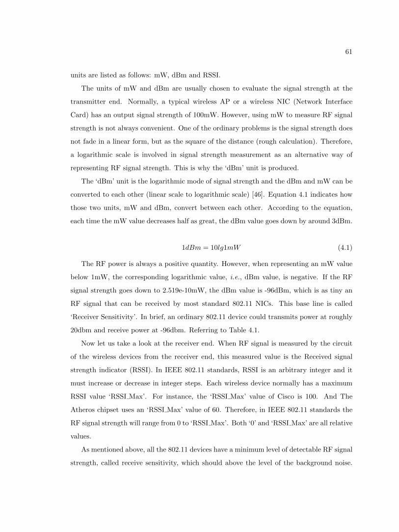
61
units are listed as follows: mW, dBm and RSSI.
The units of mW and dBm are usually chosen to evaluate the signal strength at the
transmitter end. Normally, a typical wireless AP or a wireless NIC (Network Interface
Card) has an output signal strength of 100mW. However, using mW to measure RF signal
strength is not always convenient. One of the ordinary problems is the signal strength does
not fade in a linear form, but as the square of the distance (rough calculation). Therefore,
a logarithmic scale is involved in signal strength measurement as an alternative way of
representing RF signal strength. This is why the ‘dBm’ unit is produced.
The ‘dBm’ unit is the logarithmic mode of signal strength and the dBm and mW can be
converted to each other (linear scale to logarithmic scale) [46]. Equation 4.1 indicates how
those two units, mW and dBm, convert between each other. According to the equation,
each time the mW value decreases half as great, the dBm value goes down by around 3dBm.
1dBm = 10lg1mW (4.1)
The RF power is always a positive quantity. However, when representing an mW value
below 1mW, the corresponding logarithmic value, i.e., dBm value, is negative. If the RF
signal strength goes down to 2.519e-10mW, the dBm value is -96dBm, which is as tiny an
RF signal that can be received by most standard 802.11 NICs. This base line is called
‘Receiver Sensitivity’. In brief, an ordinary 802.11 device could transmits power at roughly
20dbm and receive power at -96dbm. Referring to Table 4.1.
Now let us take a look at the receiver end. When RF signal is measured by the circuit
of the wireless devices from the receiver end, this measured value is the Received signal
strength indicator (RSSI). In IEEE 802.11 standards, RSSI is an arbitrary integer and it
must increase or decrease in integer steps. Each wireless device normally has a maximum
RSSI value ‘RSSI Max’. For instance, the ‘RSSI Max’ value of Cisco is 100. And The
Atheros chipset uses an ‘RSSI Max’ value of 60. Therefore, in IEEE 802.11 standards the
RF signal strength will range from 0 to ‘RSSI Max’. Both ‘0’ and ‘RSSI Max’ are all relative
values.
As mentioned above, all the 802.11 devices have a minimum level of detectable RF signal
strength, called receive sensitivity, which should above the level of the background noise.
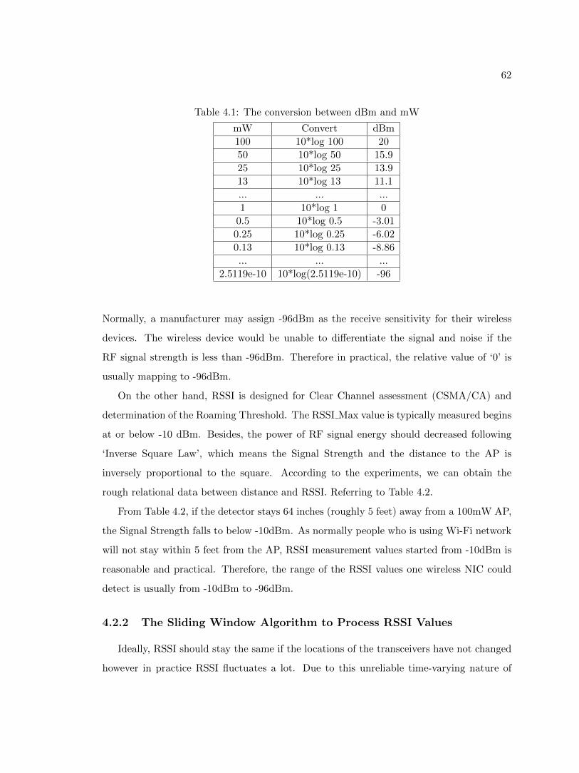
62
Table 4.1: The conversion between dBm and mW
mW Convert dBm
100 10*log 100 20
50 10*log 50 15.9
25 10*log 25 13.9
13 10*log 13 11.1
... ... ...
1 10*log 1 0
0.5 10*log 0.5 -3.01
0.25 10*log 0.25 -6.02
0.13 10*log 0.13 -8.86
... ... ...
2.5119e-10 10*log(2.5119e-10) -96
Normally, a manufacturer may assign -96dBm as the receive sensitivity for their wireless
devices. The wireless device would be unable to differentiate the signal and noise if the
RF signal strength is less than -96dBm. Therefore in practical, the relative value of ‘0’ is
usually mapping to -96dBm.
On the other hand, RSSI is designed for Clear Channel assessment (CSMA/CA) and
determination of the Roaming Threshold. The RSSI Max value is typically measured begins
at or below -10 dBm. Besides, the power of RF signal energy should decreased following
‘Inverse Square Law’, which means the Signal Strength and the distance to the AP is
inversely proportional to the square. According to the experiments, we can obtain the
rough relational data between distance and RSSI. Referring to Table 4.2.
From Table 4.2, if the detector stays 64 inches (roughly 5 feet) away from a 100mW AP,
the Signal Strength falls to below -10dBm. As normally people who is using Wi-Fi network
will not stay within 5 feet from the AP, RSSI measurement values started from -10dBm is
reasonable and practical. Therefore, the range of the RSSI values one wireless NIC could
detect is usually from -10dBm to -96dBm.
4.2.2 The Sliding Window Algorithm to Process RSSI Values
Ideally, RSSI should stay the same if the locations of the transceivers have not changed
however in practice RSSI fluctuates a lot. Due to this unreliable time-varying nature of
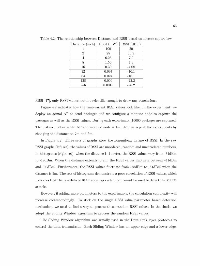
63
Table 4.2: The relationship between Distance and RSSI based on inverse-square law
Distance (inch) RSSI (mW) RSSI (dBm)
1 100 20
2 25 13.9
4 6.26 7.9
8 1.56 1.9
16 0.39 -4.08
32 0.097 -10.1
64 0.024 -16.1
128 0.006 -22.2
256 0.0015 -28.2
RSSI [47], only RSSI values are not scientific enough to draw any conclusions.
Figure 4.2 indicates how the time-variant RSSI values look like. In the experiment, we
deploy an actual AP to send packages and we configure a monitor node to capture the
packages as well as the RSSI values. During each experiment, 10000 packages are captured.
The distance between the AP and monitor node is 1m, then we repeat the experiments by
changing the distance to 2m and 5m.
In Figure 4.2. Three sets of graphs show the nonuniform nature of RSSI. In the raw
RSSI graphs (left set), the values of RSSI are unordered, random and uncorrelated numbers.
In histograms (right set), when the distance is 1 meter, the RSSI values vary from -34dBm
to -19dBm. When the distance extends to 2m, the RSSI values fluctuate between -41dBm
and -30dBm. Furthermore, the RSSI values fluctuate from -58dBm to -61dBm when the
distance is 5m. The sets of histograms demonstrate a poor correlation of RSSI values, which
indicates that the raw data of RSSI are so sporadic that cannot be used to detect the MITM
attacks.
However, if adding more parameters to the experiments, the calculation complexity will
increase correspondingly. To stick on the single RSSI value parameter based detection
mechanism, we need to find a way to process those random RSSI values. In the thesis, we
adopt the Sliding Window algorithm to process the random RSSI values.
The Sliding Window algorithm was usually used in the Data Link layer protocols to
control the data transmission. Each Sliding Window has an upper edge and a lower edge,
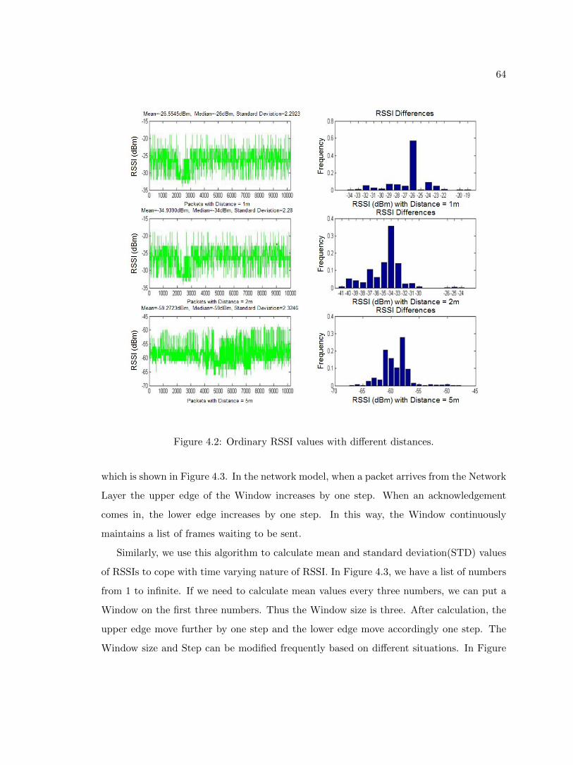
64
Figure 4.2: Ordinary RSSI values with different distances.
which is shown in Figure 4.3. In the network model, when a packet arrives from the Network
Layer the upper edge of the Window increases by one step. When an acknowledgement
comes in, the lower edge increases by one step. In this way, the Window continuously
maintains a list of frames waiting to be sent.
Similarly, we use this algorithm to calculate mean and standard deviation(STD) values
of RSSIs to cope with time varying nature of RSSI. In Figure 4.3, we have a list of numbers
from 1 to infinite. If we need to calculate mean values every three numbers, we can put a
Window on the first three numbers. Thus the Window size is three. After calculation, the
upper edge move further by one step and the lower edge move accordingly one step. The
Window size and Step can be modified frequently based on different situations. In Figure
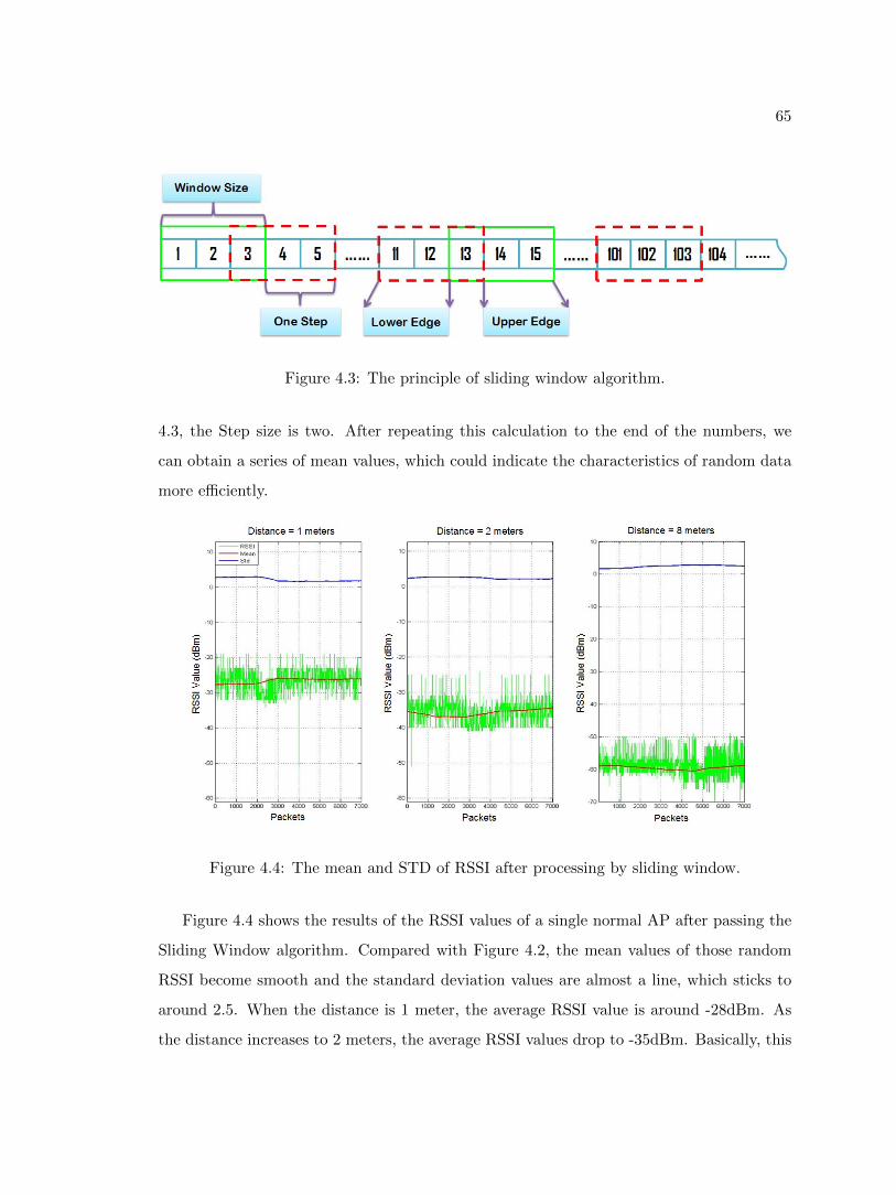
65
Figure 4.3: The principle of sliding window algorithm.
4.3, the Step size is two. After repeating this calculation to the end of the numbers, we
can obtain a series of mean values, which could indicate the characteristics of random data
more efficiently.
Figure 4.4: The mean and STD of RSSI after processing by sliding window.
Figure 4.4 shows the results of the RSSI values of a single normal AP after passing the
Sliding Window algorithm. Compared with Figure 4.2, the mean values of those random
RSSI become smooth and the standard deviation values are almost a line, which sticks to
around 2.5. When the distance is 1 meter, the average RSSI value is around -28dBm. As
the distance increases to 2 meters, the average RSSI values drop to -35dBm. Basically, this
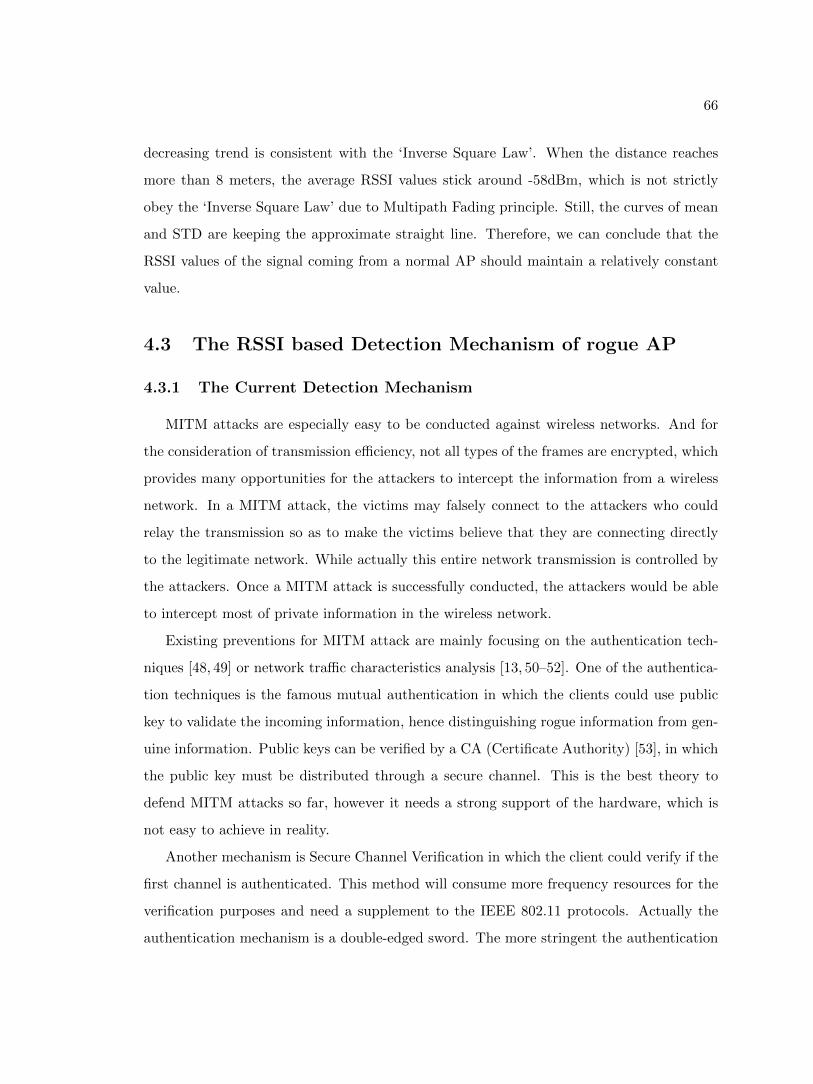
66
decreasing trend is consistent with the ‘Inverse Square Law’. When the distance reaches
more than 8 meters, the average RSSI values stick around -58dBm, which is not strictly
obey the ‘Inverse Square Law’ due to Multipath Fading principle. Still, the curves of mean
and STD are keeping the approximate straight line. Therefore, we can conclude that the
RSSI values of the signal coming from a normal AP should maintain a relatively constant
value.
4.3 The RSSI based Detection Mechanism of rogue AP
4.3.1 The Current Detection Mechanism
MITM attacks are especially easy to be conducted against wireless networks. And for
the consideration of transmission efficiency, not all types of the frames are encrypted, which
provides many opportunities for the attackers to intercept the information from a wireless
network. In a MITM attack, the victims may falsely connect to the attackers who could
relay the transmission so as to make the victims believe that they are connecting directly
to the legitimate network. While actually this entire network transmission is controlled by
the attackers. Once a MITM attack is successfully conducted, the attackers would be able
to intercept most of private information in the wireless network.
Existing preventions for MITM attack are mainly focusing on the authentication tech-
niques [48, 49] or network traffic characteristics analysis [13, 50–52]. One of the authentica-
tion techniques is the famous mutual authentication in which the clients could use public
key to validate the incoming information, hence distinguishing rogue information from gen-
uine information. Public keys can be verified by a CA (Certificate Authority) [53], in which
the public key must be distributed through a secure channel. This is the best theory to
defend MITM attacks so far, however it needs a strong support of the hardware, which is
not easy to achieve in reality.
Another mechanism is Secure Channel Verification in which the client could verify if the
first channel is authenticated. This method will consume more frequency resources for the
verification purposes and need a supplement to the IEEE 802.11 protocols. Actually the
authentication mechanism is a double-edged sword. The more stringent the authentication
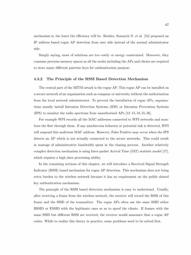
67
mechanism is, the lower the efficiency will be. Besides, Somayeh N. et al. [54] proposed an
IP address based rogue AP detection from user side instead of the normal administrator
side.
Simply saying, most of solutions are too costly or energy constrained. Moreover, they
consume precious memory spaces as all the nodes including the APs and clients are required
to store many different pairwise keys for authentication purpose.
4.3.2 The Principle of the RSSI Based Detection Mechanism
The central part of the MITM attack is the rogue AP. This rogue AP can be installed on
a secure network of an organization such as company or university without the authorization
from the local network administrator. To prevent the installation of rogue APs, organiza-
tions usually install Intrusion Detection Systems (IDS) or Intrusion Prevention Systems
(IPS) to monitor the radio spectrum from unauthorized APs [12–15, 18, 55, 56].
For example WPI records all the MAC addresses connected to WPI networks and mon-
itors the flow through them. If any mischievous behavior or potential risk is detected, WPI
will suspend this malicious MAC address. However, False Positive may occur when the IPS
detects an AP which is not actually connected to the secure networks. This could result
in wastage of administrative bandwidth spent in the chasing process. Another relatively
complex detection mechanism is using Inter-packet Arrival Time (IAT) statistic model [17],
which requires a high data processing ability.
In the remaining sections of this chapter, we will introduce a Received Signal Strength
Indicator (RSSI) based mechanism for rogue AP detection. This mechanism does not bring
extra burden to the wireless network because it has no requirement on the public shared
key authentication mechanism.
The principle of the RSSI based detection mechanism is easy to understand. Usually,
after receiving a frame from the wireless network, the receiver will record the RSSI of this
frame and the SSID of the transmitter. The rogue APs often use the same SSID either
BSSID or ESSID with the legitimate ones so as to spoof the clients. If frames with the
same SSID but different RSSI are received, the receiver would announce that a rogue AP
exists. While to realize this theory in practice, some problems need to be solved first.
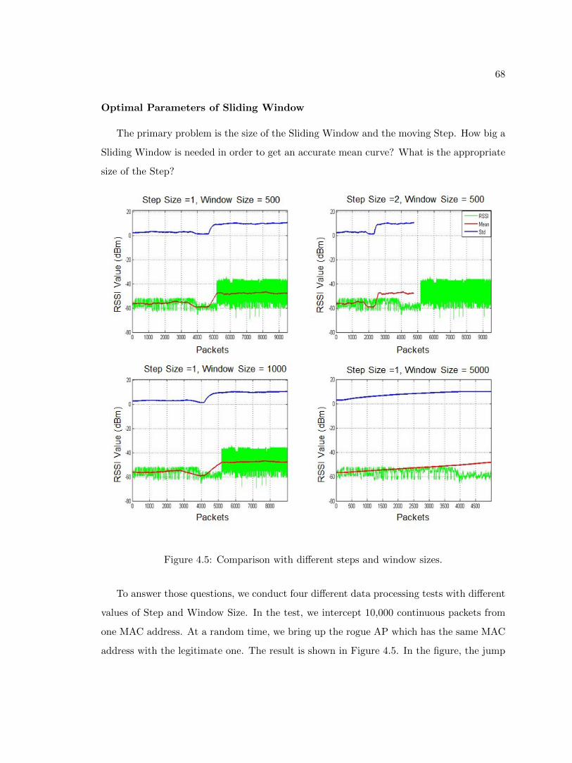
68
Optimal Parameters of Sliding Window
The primary problem is the size of the Sliding Window and the moving Step. How big a
Sliding Window is needed in order to get an accurate mean curve? What is the appropriate
size of the Step?
Figure 4.5: Comparison with different steps and window sizes.
To answer those questions, we conduct four different data processing tests with different
values of Step and Window Size. In the test, we intercept 10,000 continuous packets from
one MAC address. At a random time, we bring up the rogue AP which has the same MAC
address with the legitimate one. The result is shown in Figure 4.5. In the figure, the jump
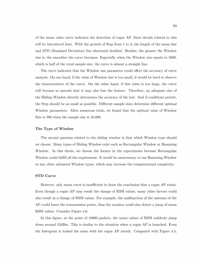
69
of the mean value curve indicates the detection of rogue AP. More details related to this
will be introduced later. With the growth of Step from 1 to 2, the length of the mean line
and STD (Standard Deviation) line shortened doubled. Besides, the greater the Window
size is, the smoother the curve becomes. Especially when the Window size equals to 5000,
which is half of the total sample size, the curve is almost a straight line.
The curve indicates that the Window size parameter could effect the accuracy of curve
analysis. On one hand, if the value of Window size is too small, it would be hard to observe
the characteristics of the curve. On the other hand, if this value is too large, the curve
will become so smooth that it may also lose the feature. Therefore, an adequate size of
the Sliding Window directly determines the accuracy of the test. And if conditions permit,
the Step should be as small as possible. Different sample sizes determine different optimal
Window parameters. After numerous trials, we found that the optimal value of Window
Size is 500 when the sample size is 10,000.
The Type of Window
The second question related to the sliding window is that which Window type should
we choose. Many types of Sliding Window exist such as Rectangular Window or Hamming
Window. In this thesis, we choose the former in the experiments because Rectangular
Window could fulfill all the requirement. It would be unnecessary to use Hamming Window
or any other advanced Window types, which may increase the computational complexity.
STD Curve
However, only mean curve is insufficient to draw the conclusion that a rogue AP exists.
Even though a rogue AP may result the change of RSSI values, many other factors could
also result in a change of RSSI values. For example, the malfunction of the antenna of the
AP could lower the transmission power, thus the monitor could also detect a jump of mean
RSSI values. Consider Figure 4.6.
In this figure, at the point of 10000 packets, the mean values of RSSI suddenly jump
down around 12dBm. This is similar to the situation when a rogue AP is launched. Even
the histogram is looked the same with the rogue AP attack. Compared with Figure 4.5,
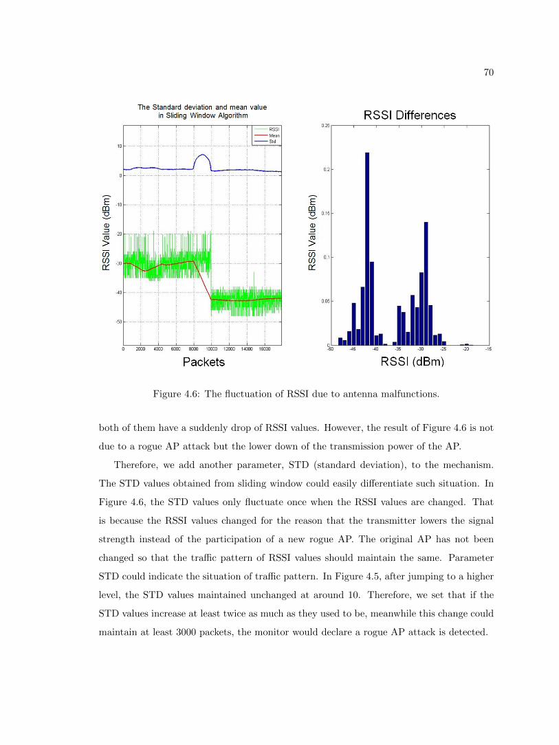
70
Figure 4.6: The fluctuation of RSSI due to antenna malfunctions.
both of them have a suddenly drop of RSSI values. However, the result of Figure 4.6 is not
due to a rogue AP attack but the lower down of the transmission power of the AP.
Therefore, we add another parameter, STD (standard deviation), to the mechanism.
The STD values obtained from sliding window could easily differentiate such situation. In
Figure 4.6, the STD values only fluctuate once when the RSSI values are changed. That
is because the RSSI values changed for the reason that the transmitter lowers the signal
strength instead of the participation of a new rogue AP. The original AP has not been
changed so that the traffic pattern of RSSI values should maintain the same. Parameter
STD could indicate the situation of traffic pattern. In Figure 4.5, after jumping to a higher
level, the STD values maintained unchanged at around 10. Therefore, we set that if the
STD values increase at least twice as much as they used to be, meanwhile this change could
maintain at least 3000 packets, the monitor would declare a rogue AP attack is detected.
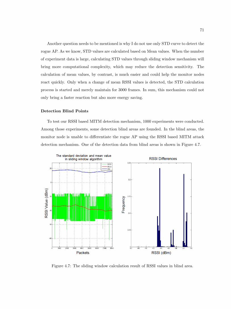
71
Another question needs to be mentioned is why I do not use only STD curve to detect the
rogue AP. As we know, STD values are calculated based on Mean values. When the number
of experiment data is large, calculating STD values through sliding window mechanism will
bring more computational complexity, which may reduce the detection sensitivity. The
calculation of mean values, by contrast, is much easier and could help the monitor nodes
react quickly. Only when a change of mean RSSI values is detected, the STD calculation
process is started and merely maintain for 3000 frames. In sum, this mechanism could not
only bring a faster reaction but also more energy saving.
Detection Blind Points
To test our RSSI based MITM detection mechanism, 1000 experiments were conducted.
Among those experiments, some detection blind areas are founded. In the blind areas, the
monitor node is unable to differentiate the rogue AP using the RSSI based MITM attack
detection mechanism. One of the detection data from blind areas is shown in Figure 4.7.
Figure 4.7: The sliding window calculation result of RSSI values in blind area.
72
In the histogram of Figure 4.7, the distribution of RSSI values concentrates in three
areas, -15dBm to -20dBm, -30dBm to -40dBm, -50dBm to -55dBm, which seems abnormal.
However we cannot tell if a rogue AP exists from RSSI characteristic pattern because the
span of RSSI values range from -18dBm to -55dBm and both mean and STD values in
sliding window mode are less than the thresholds. Thus we cannot detect the rogue AP at
this area using the RSSI based MITM mechanism. This is a False Negative (FN) because
the rogue AP does exist. Similar blind areas are distributed within the detection areas.
Each blind area is a nearly circle with a radius of 3 meters.
Transmitter
Receiver 1
Receiver 2
Reflection
Direct Transmission
Diffraction
Scattering
Collision
Figure 4.8: The sketch of radio frequency propagation.
Now it is necessary to introduce the Multipath Fading Principle. Consider Figure 4.8.
The ‘Inverse Square Law’ is a rough calculation of the relationship between signal strength
and distance. The signal is actually an electromagnetic wave, which may reflect many
hops before arriving at the receiver. Besides, the electromagnetic wave may also need to
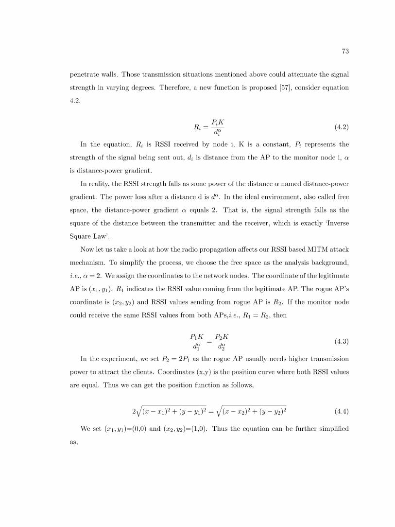
73
penetrate walls. Those transmission situations mentioned above could attenuate the signal
strength in varying degrees. Therefore, a new function is proposed [57], consider equation
4.2.
Ri =PiK
dαi(4.2)
In the equation, Ri is RSSI received by node i, K is a constant, Pi represents the
strength of the signal being sent out, di is distance from the AP to the monitor node i, α
is distance-power gradient.
In reality, the RSSI strength falls as some power of the distance α named distance-power
gradient. The power loss after a distance d is dα. In the ideal environment, also called free
space, the distance-power gradient α equals 2. That is, the signal strength falls as the
square of the distance between the transmitter and the receiver, which is exactly ‘Inverse
Square Law’.
Now let us take a look at how the radio propagation affects our RSSI based MITM attack
mechanism. To simplify the process, we choose the free space as the analysis background,
i.e., α= 2. We assign the coordinates to the network nodes. The coordinate of the legitimate
AP is (x1, y1). R1 indicates the RSSI value coming from the legitimate AP. The rogue AP’s
coordinate is (x2, y2) and RSSI values sending from rogue AP is R2. If the monitor node
could receive the same RSSI values from both APs,i.e., R1 = R2, then
P1K
dα1=P2K
dα2(4.3)
In the experiment, we set P2 = 2P1 as the rogue AP usually needs higher transmission
power to attract the clients. Coordinates (x,y) is the position curve where both RSSI values
are equal. Thus we can get the position function as follows,
2√
(x− x1)2 + (y − y1)2 =√
(x− x2)2 + (y − y2)2 (4.4)
We set (x1, y1)=(0,0) and (x2, y2)=(1,0). Thus the equation can be further simplified
as,
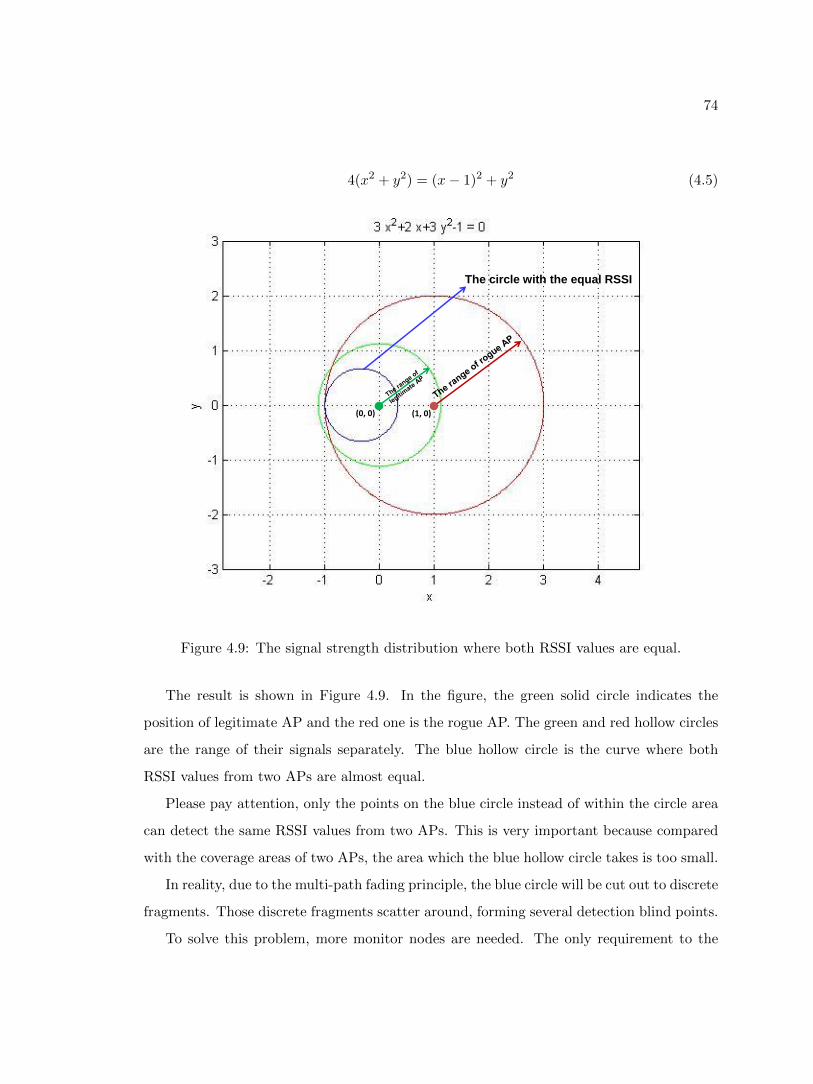
74
4(x2 + y2) = (x− 1)2 + y2 (4.5)
(1, 0) (0, 0)
The circle with the equal RSSI
Figure 4.9: The signal strength distribution where both RSSI values are equal.
The result is shown in Figure 4.9. In the figure, the green solid circle indicates the
position of legitimate AP and the red one is the rogue AP. The green and red hollow circles
are the range of their signals separately. The blue hollow circle is the curve where both
RSSI values from two APs are almost equal.
Please pay attention, only the points on the blue circle instead of within the circle area
can detect the same RSSI values from two APs. This is very important because compared
with the coverage areas of two APs, the area which the blue hollow circle takes is too small.
In reality, due to the multi-path fading principle, the blue circle will be cut out to discrete
fragments. Those discrete fragments scatter around, forming several detection blind points.
To solve this problem, more monitor nodes are needed. The only requirement to the
75
positions of those monitor nodes is they should be placed around the legitimate AP as
sporadic as possible. Then I set monitor node 1 as the control monitor. When a monitor
node detect a rogue AP, it will send the detection result along with the calculation data to
the control node, i.e., node 1. The control node will not only perform the MITM detection
mechanism itself but also examine all the report it has received from the other nodes. If at
least one node declares an rogue AP attack, the control monitor will announce that a rogue
AP attack is detected.
The Communication Mode of the Monitor Nodes
As more than one monitor nodes are needed to detect the MITM attack, how to commu-
nication with each other or send the attack notice to the control node becomes a problem.
Due to the presentence of rogue AP, we have reasons to believe that the legitimate Wi-Fi
network is not trustworthy anymore. The transmission between the monitor nodes may be
intercepted or corrupted. Therefore, which network can we use to send detection messages?
One way is to use the UTP cable to connect the monitor nodes, letting them commu-
nicate with each other through Ethernet. Indeed, this way could resist the wireless MITM
attack. The weak points, however, are also obvious. For one thing, making and arranging
the UTP cables will greatly run up costs. For another, wired network greatly limits the
detection of flexibility.
Another substitute is still using the official wireless network but encrypting the infor-
mation such as the attack notice. However, encrypting and decrypting the information
will tremendous reduce the efficiency and increase the burden of detection system, not to
mention that the attacker may still corrupt the transmission between the monitor nodes.
The third way is using the other network carriers such as the 3G or LTE network.
Transmission through cellular networks could bypass the MITM attack restrictions and the
speed is enough to send and receive the detection information. However, the cost for the
data flow is quite high.
Therefore, one of the cheap and reliable transmission method, which is also the method
I use in the experiment is the ad-hoc network. In the experiment, the three monitor nodes
are three computers. All of them are configured into ad-hoc mode. The transmission based
76
on the ad-hoc network does not need the legitimate AP. Thus the attacker would be hard
to detect or attack the detection mechanisms.
As the basic operation of this detection mechanism is calculating the mean and STD
values in Sliding Window, using up to three computers is quite wasteful. A better idea is
choosing the WSN (Wireless Sensor Network). A WSN consists of distributed sensors to
monitor specific conditions. The cost for the sensors are relatively low and those sensors
have great flexibility.
The Algorithm of Detection Mechanism
We have introduced the basic principle of RSSI based MITM attack detection mechanis-
m. Now it is necessary to further discuss the details of this mechanism. In the experiment,
two parameters were used to determine if a rogue AP exists. That is, mean value and STD
(standard deviation) value. The basic flow process of RSSI based detection mechanism is
shown in Figure 4.10.
In Figure 4.10, the monitor node starts by monitoring the RSSI values received from the
same SSID and pass the RSSI through Sliding Window algorithm. Then keep monitoring
the mean curve of RSSI. Once the rogue AP is launched, the RSSI values will fluctuate. The
curve of mean values after processing by Sliding Window algorithm will jump to another
lever either higher or lower than before. When a jump of mean value is detected, i.e., the
mean change is larger than Threshold 1, the monitor node will calculate the STD curve for
3000 frames in Sliding Windows. If the STD is greater than Threshold 2, the monitor node
will announce that a rogue AP is detected. Otherwise, the monitor node just record the
results and keep monitoring the mean curve of RSSI.
Actually, this jump value may be decided by varieties of elements such as the distance
between the legitimate AP and rogue AP, the detection position of the monitor nodes as
well as the transmission power of both APs. From Figure 4.5, the jump of the mean value
of RSSI could reach up to -10dBm. Here, we setup a threshold 1 at 5dBm. If the jump
value of the mean curve is equal or higher than 5dBm, the monitor node will declare a rogue
AP exists. Otherwise, if the jump value of the mean curve is less than 5dBm, the monitor
node would consider everything is normal. Please notice that the threshold of 5dBm is for
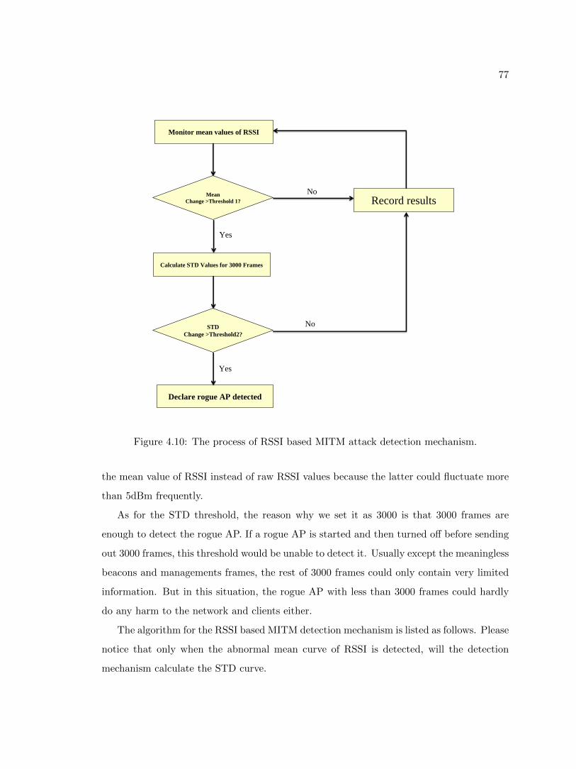
77
Monitor mean values of RSSI
Mean
Change >Threshold 1?
Calculate STD Values for 3000 Frames
STD
Change >Threshold2?
Declare rogue AP detected
Record results No
Yes
No
Yes
Figure 4.10: The process of RSSI based MITM attack detection mechanism.
the mean value of RSSI instead of raw RSSI values because the latter could fluctuate more
than 5dBm frequently.
As for the STD threshold, the reason why we set it as 3000 is that 3000 frames are
enough to detect the rogue AP. If a rogue AP is started and then turned off before sending
out 3000 frames, this threshold would be unable to detect it. Usually except the meaningless
beacons and managements frames, the rest of 3000 frames could only contain very limited
information. But in this situation, the rogue AP with less than 3000 frames could hardly
do any harm to the network and clients either.
The algorithm for the RSSI based MITM detection mechanism is listed as follows. Please
notice that only when the abnormal mean curve of RSSI is detected, will the detection
mechanism calculate the STD curve.
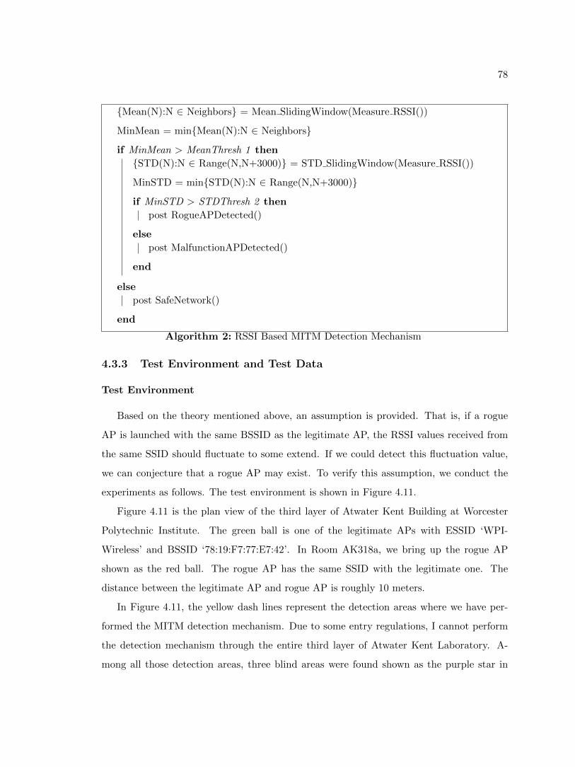
78
{Mean(N):N ∈ Neighbors} = Mean SlidingWindow(Measure RSSI())
MinMean = min{Mean(N):N ∈ Neighbors}
if MinMean > MeanThresh 1 then
{STD(N):N ∈ Range(N,N+3000)} = STD SlidingWindow(Measure RSSI())
MinSTD = min{STD(N):N ∈ Range(N,N+3000)}
if MinSTD > STDThresh 2 then
post RogueAPDetected()
else
post MalfunctionAPDetected()
end
else
post SafeNetwork()
end
Algorithm 2: RSSI Based MITM Detection Mechanism
4.3.3 Test Environment and Test Data
Test Environment
Based on the theory mentioned above, an assumption is provided. That is, if a rogue
AP is launched with the same BSSID as the legitimate AP, the RSSI values received from
the same SSID should fluctuate to some extend. If we could detect this fluctuation value,
we can conjecture that a rogue AP may exist. To verify this assumption, we conduct the
experiments as follows. The test environment is shown in Figure 4.11.
Figure 4.11 is the plan view of the third layer of Atwater Kent Building at Worcester
Polytechnic Institute. The green ball is one of the legitimate APs with ESSID ‘WPI-
Wireless’ and BSSID ‘78:19:F7:77:E7:42’. In Room AK318a, we bring up the rogue AP
shown as the red ball. The rogue AP has the same SSID with the legitimate one. The
distance between the legitimate AP and rogue AP is roughly 10 meters.
In Figure 4.11, the yellow dash lines represent the detection areas where we have per-
formed the MITM detection mechanism. Due to some entry regulations, I cannot perform
the detection mechanism through the entire third layer of Atwater Kent Laboratory. A-
mong all those detection areas, three blind areas were found shown as the purple star in
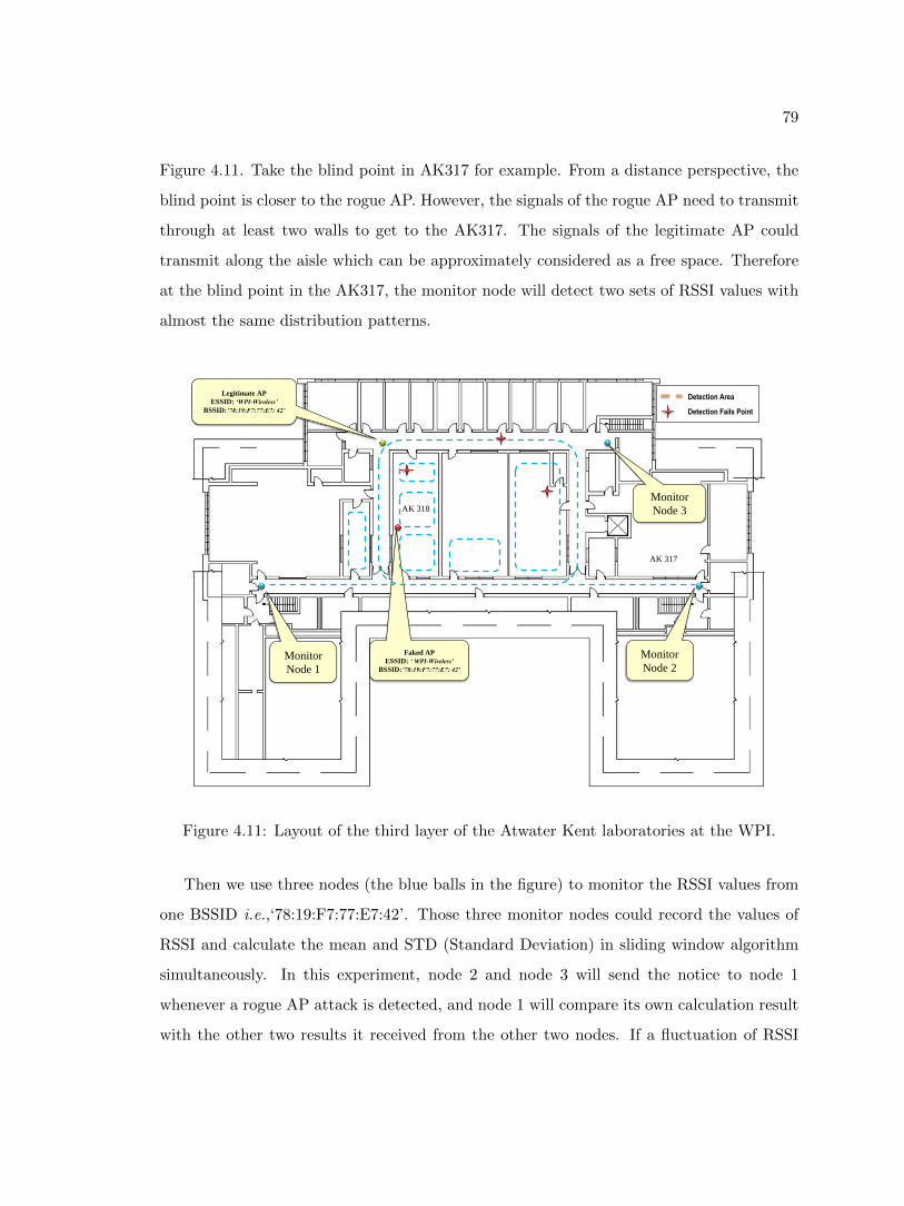
79
Figure 4.11. Take the blind point in AK317 for example. From a distance perspective, the
blind point is closer to the rogue AP. However, the signals of the rogue AP need to transmit
through at least two walls to get to the AK317. The signals of the legitimate AP could
transmit along the aisle which can be approximately considered as a free space. Therefore
at the blind point in the AK317, the monitor node will detect two sets of RSSI values with
almost the same distribution patterns.
Legitimate AP
ESSID: ‘WPI-Wireless’
BSSID:’78:19:F7:77:E7: 42’
Monitor
Node 3
Faked AP
ESSID: ‘ WPI-Wireless’
BSSID:’78:19:F7:77:E7: 42’
Monitor
Node 1
Monitor
Node 2
Detection Area
Detection Fails Point
AK 317
AK 318
Figure 4.11: Layout of the third layer of the Atwater Kent laboratories at the WPI.
Then we use three nodes (the blue balls in the figure) to monitor the RSSI values from
one BSSID i.e.,‘78:19:F7:77:E7:42’. Those three monitor nodes could record the values of
RSSI and calculate the mean and STD (Standard Deviation) in sliding window algorithm
simultaneously. In this experiment, node 2 and node 3 will send the notice to node 1
whenever a rogue AP attack is detected, and node 1 will compare its own calculation result
with the other two results it received from the other two nodes. If a fluctuation of RSSI
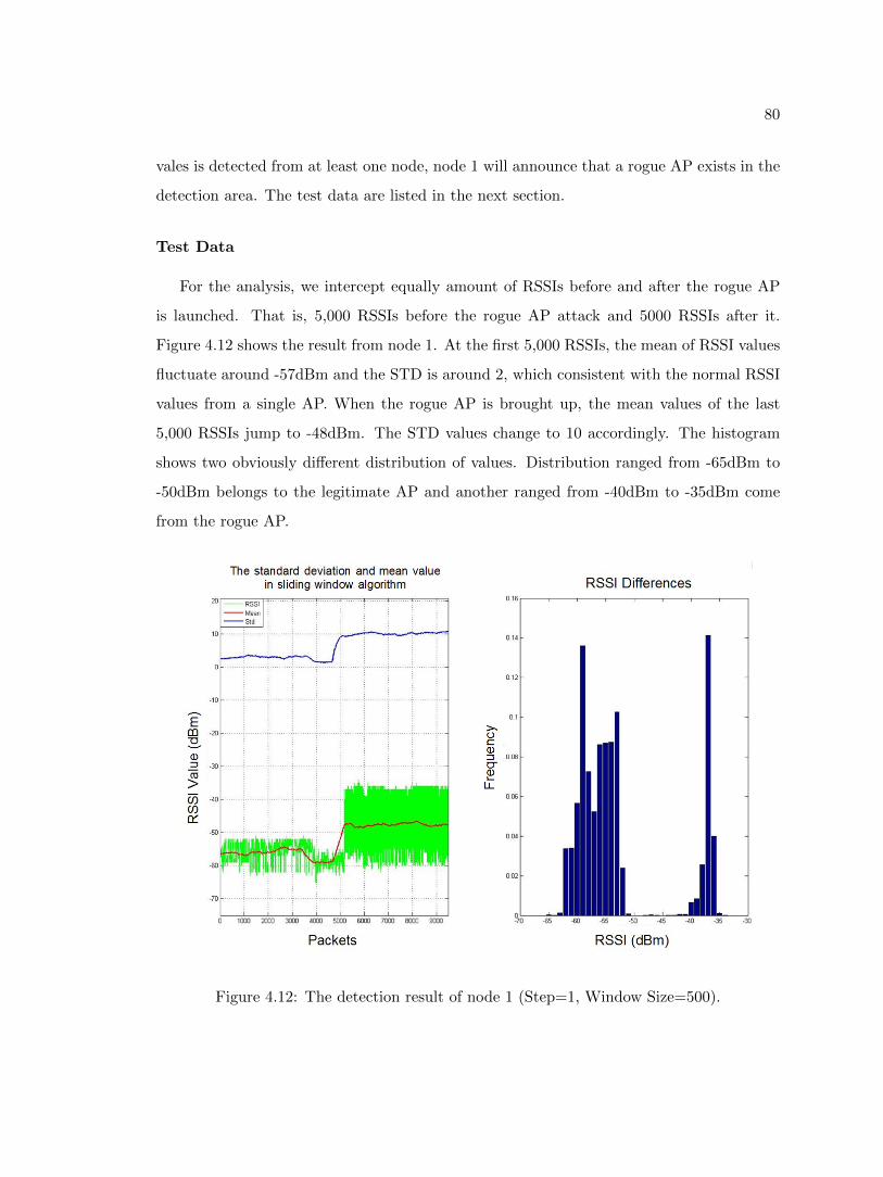
80
vales is detected from at least one node, node 1 will announce that a rogue AP exists in the
detection area. The test data are listed in the next section.
Test Data
For the analysis, we intercept equally amount of RSSIs before and after the rogue AP
is launched. That is, 5,000 RSSIs before the rogue AP attack and 5000 RSSIs after it.
Figure 4.12 shows the result from node 1. At the first 5,000 RSSIs, the mean of RSSI values
fluctuate around -57dBm and the STD is around 2, which consistent with the normal RSSI
values from a single AP. When the rogue AP is brought up, the mean values of the last
5,000 RSSIs jump to -48dBm. The STD values change to 10 accordingly. The histogram
shows two obviously different distribution of values. Distribution ranged from -65dBm to
-50dBm belongs to the legitimate AP and another ranged from -40dBm to -35dBm come
from the rogue AP.
Figure 4.12: The detection result of node 1 (Step=1, Window Size=500).
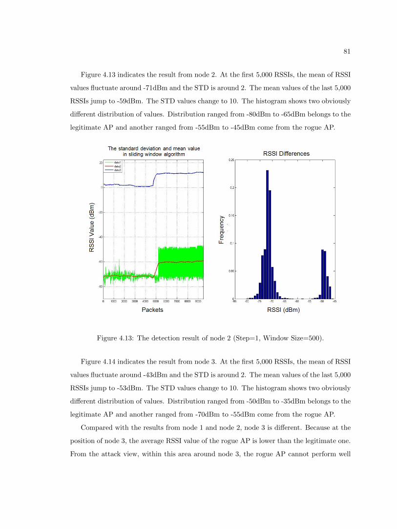
81
Figure 4.13 indicates the result from node 2. At the first 5,000 RSSIs, the mean of RSSI
values fluctuate around -71dBm and the STD is around 2. The mean values of the last 5,000
RSSIs jump to -59dBm. The STD values change to 10. The histogram shows two obviously
different distribution of values. Distribution ranged from -80dBm to -65dBm belongs to the
legitimate AP and another ranged from -55dBm to -45dBm come from the rogue AP.
Figure 4.13: The detection result of node 2 (Step=1, Window Size=500).
Figure 4.14 indicates the result from node 3. At the first 5,000 RSSIs, the mean of RSSI
values fluctuate around -43dBm and the STD is around 2. The mean values of the last 5,000
RSSIs jump to -53dBm. The STD values change to 10. The histogram shows two obviously
different distribution of values. Distribution ranged from -50dBm to -35dBm belongs to the
legitimate AP and another ranged from -70dBm to -55dBm come from the rogue AP.
Compared with the results from node 1 and node 2, node 3 is different. Because at the
position of node 3, the average RSSI value of the rogue AP is lower than the legitimate one.
From the attack view, within this area around node 3, the rogue AP cannot perform well
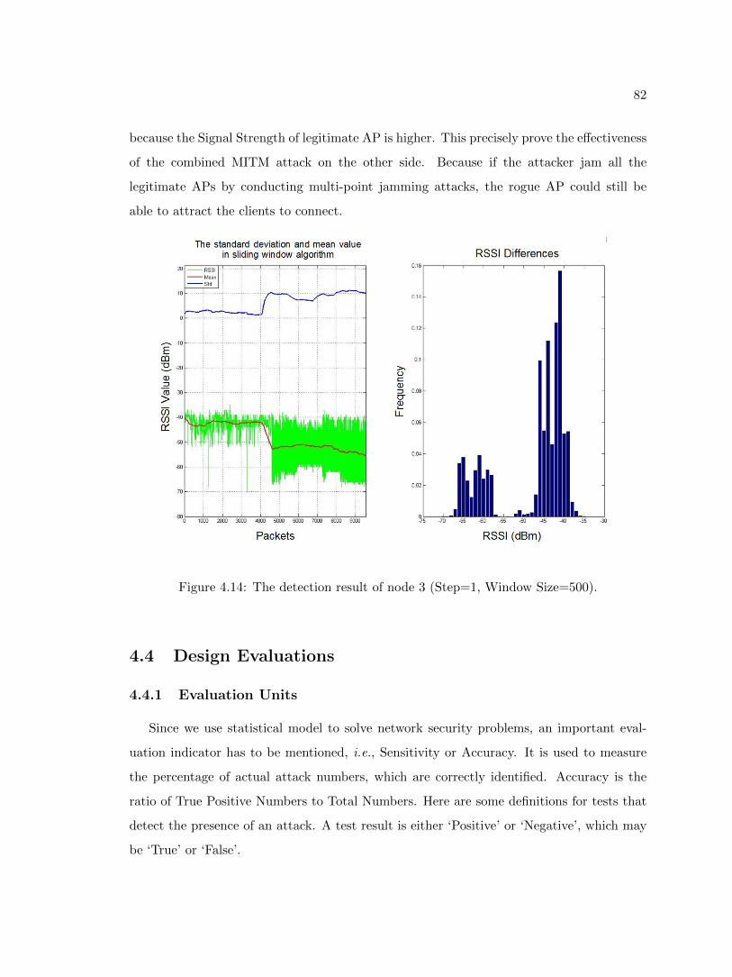
82
because the Signal Strength of legitimate AP is higher. This precisely prove the effectiveness
of the combined MITM attack on the other side. Because if the attacker jam all the
legitimate APs by conducting multi-point jamming attacks, the rogue AP could still be
able to attract the clients to connect.
Figure 4.14: The detection result of node 3 (Step=1, Window Size=500).
4.4 Design Evaluations
4.4.1 Evaluation Units
Since we use statistical model to solve network security problems, an important eval-
uation indicator has to be mentioned, i.e., Sensitivity or Accuracy. It is used to measure
the percentage of actual attack numbers, which are correctly identified. Accuracy is the
ratio of True Positive Numbers to Total Numbers. Here are some definitions for tests that
detect the presence of an attack. A test result is either ‘Positive’ or ‘Negative’, which may
be ‘True’ or ‘False’.
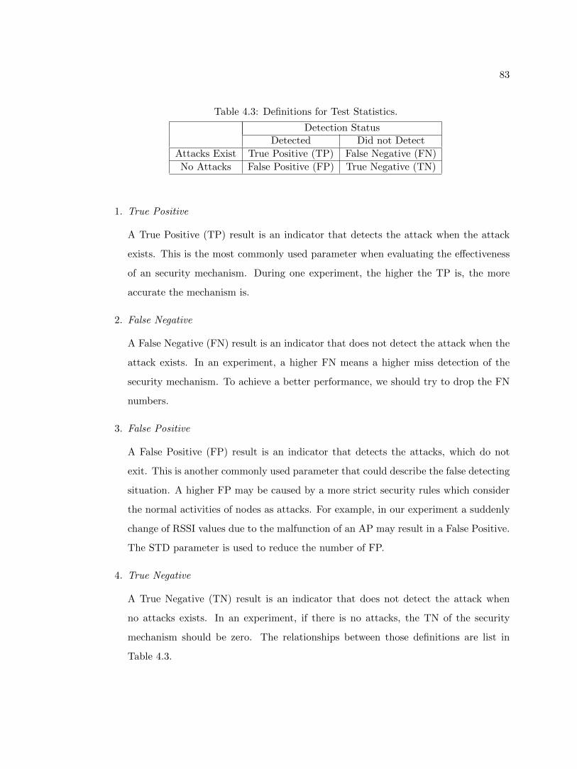
83
Table 4.3: Definitions for Test Statistics.
Detection StatusDetected Did not Detect
Attacks Exist True Positive (TP) False Negative (FN)
No Attacks False Positive (FP) True Negative (TN)
1. True Positive
A True Positive (TP) result is an indicator that detects the attack when the attack
exists. This is the most commonly used parameter when evaluating the effectiveness
of an security mechanism. During one experiment, the higher the TP is, the more
accurate the mechanism is.
2. False Negative
A False Negative (FN) result is an indicator that does not detect the attack when the
attack exists. In an experiment, a higher FN means a higher miss detection of the
security mechanism. To achieve a better performance, we should try to drop the FN
numbers.
3. False Positive
A False Positive (FP) result is an indicator that detects the attacks, which do not
exit. This is another commonly used parameter that could describe the false detecting
situation. A higher FP may be caused by a more strict security rules which consider
the normal activities of nodes as attacks. For example, in our experiment a suddenly
change of RSSI values due to the malfunction of an AP may result in a False Positive.
The STD parameter is used to reduce the number of FP.
4. True Negative
A True Negative (TN) result is an indicator that does not detect the attack when
no attacks exists. In an experiment, if there is no attacks, the TN of the security
mechanism should be zero. The relationships between those definitions are list in
Table 4.3.
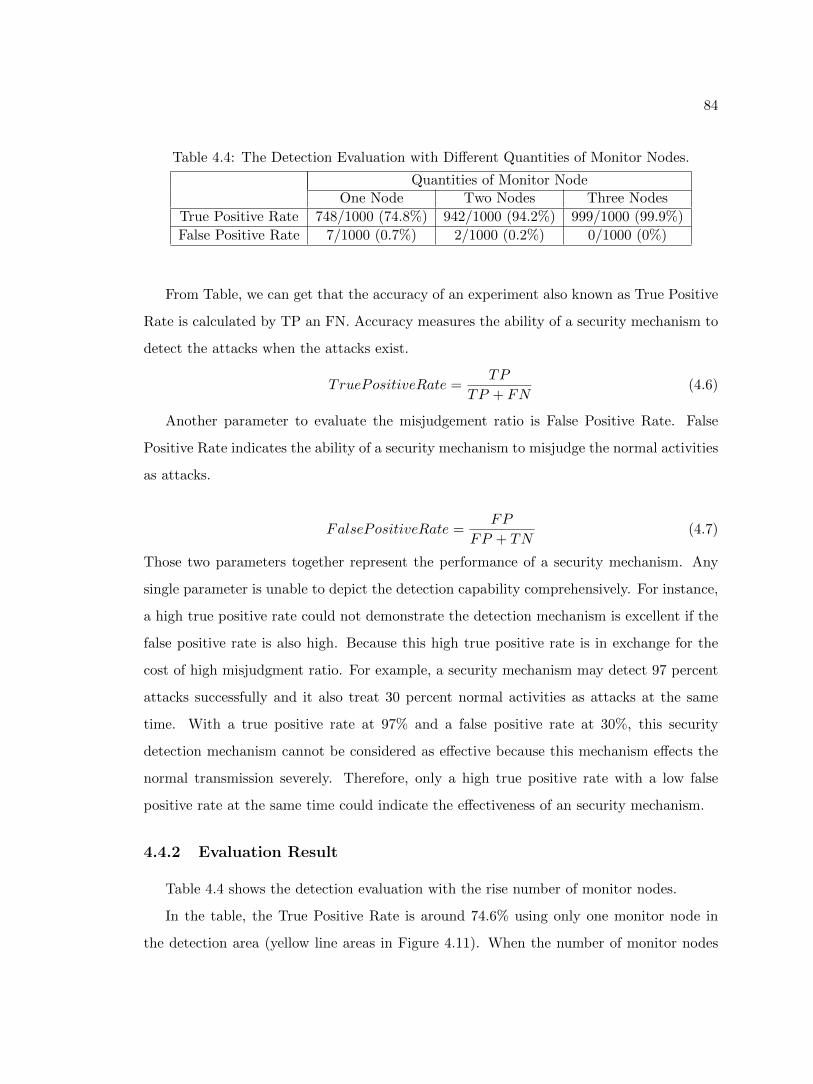
84
Table 4.4: The Detection Evaluation with Different Quantities of Monitor Nodes.
Quantities of Monitor NodeOne Node Two Nodes Three Nodes
True Positive Rate 748/1000 (74.8%) 942/1000 (94.2%) 999/1000 (99.9%)
False Positive Rate 7/1000 (0.7%) 2/1000 (0.2%) 0/1000 (0%)
From Table, we can get that the accuracy of an experiment also known as True Positive
Rate is calculated by TP an FN. Accuracy measures the ability of a security mechanism to
detect the attacks when the attacks exist.
TruePositiveRate =TP
TP + FN(4.6)
Another parameter to evaluate the misjudgement ratio is False Positive Rate. False
Positive Rate indicates the ability of a security mechanism to misjudge the normal activities
as attacks.
FalsePositiveRate =FP
FP + TN(4.7)
Those two parameters together represent the performance of a security mechanism. Any
single parameter is unable to depict the detection capability comprehensively. For instance,
a high true positive rate could not demonstrate the detection mechanism is excellent if the
false positive rate is also high. Because this high true positive rate is in exchange for the
cost of high misjudgment ratio. For example, a security mechanism may detect 97 percent
attacks successfully and it also treat 30 percent normal activities as attacks at the same
time. With a true positive rate at 97% and a false positive rate at 30%, this security
detection mechanism cannot be considered as effective because this mechanism effects the
normal transmission severely. Therefore, only a high true positive rate with a low false
positive rate at the same time could indicate the effectiveness of an security mechanism.
4.4.2 Evaluation Result
Table 4.4 shows the detection evaluation with the rise number of monitor nodes.
In the table, the True Positive Rate is around 74.6% using only one monitor node in
the detection area (yellow line areas in Figure 4.11). When the number of monitor nodes
85
increase to two (node1 and node2), the True Positive Rate will also rise to 94.2% and the
False Positive Rate drops to 0.2%. This result is actually good enough in most cases. When
there are three monitor nodes in the area, the True Positive Rate is 99.9% and the False
Positive Rate is 0%.
4.5 Chapter Summary
We presented an RSSI based detection mechanism for the MITM attack in wireless
network. We prove that even though the RSSI is time-varying and unreliable, using Sliding
Window is feasible to overcome the problem. Our protocol is robust because we detect the
rogue AP with an accuracy of 99% with the collaboration of two other monitor nodes and
zero false positive.
The first section of this Chapter aims at the detection of jamming attacks, which are
performed in Chapter 3. We first detect the presence of jamming attacks using Signal
Strength Consistency Checks. The principle is jamming attacks will cause a drop of RDR
yet many other factors could also cause a drop of PDR. We use the Signal Strength as
the Consistency to rule out other factors. If a drop of RDR is detected with a high Signal
Strength at the same time, we can conclude that jamming attacks are detected. Then we
use PDR Consistency Checks to further differentiate the types of jamming attack. This
could decrease the reaction time so as to increase the defence efficiency. Both PSR and
PDR can be calculated at the transmitter end. In PDR Consistency Checks, we first divide
the jamming attacks into two groups according to the value of PSR. Then the jamming
attacks can be further divided into four types depends on the value of PDR.
The rest of Chapter 4 focuses on the detection of MITM attacks. The key part of the
MITM attacks is the rogue AP. If we could detect the rogue AP, we can detect MITM
attacks. Usually a rogue AP has the same SSID with the legitimate AP as well as more
powerful signal strength to attract the clients. Therefore a monitor node could detect the
rogue AP by monitoring the RSSI values. In theory, if we obtained two different sets of
RSSI values from one SSID we can conclude that a rogue AP is detected.
In reality, some problems need to be solved. The first is we need to process the raw
86
meaningless RSSI values so that we can recognize the characteristics of RSSI. Thus a Sliding
Window mechanism is used to process RSSI values. After passing through the Sliding
Window, the RSSI values reveal their characteristics in mean curve. Then next question is
sometimes normal reason such as low power of an AP could also result a similar phenomenon
like a rogue AP. To solve this problem, another parameter STD is added. Only when STD
curve remains unchanged after jump to a high lever, can we conclude that a rogue AP is
detected. The third problem is several detect blind points are found in the detection area.
Detection blind point is some place that the monitor nodes could detect the same RSSI
values from two different APs. Then from the theory analysis, we know that the blind areas
are only a small part of the overall coverage areas. To overcome this problem, we add more
monitor nodes, which are installed sporadically.
Finally in the chapter, we evaluate the effectiveness of this RSSI based MITM attack
mechanism. When only one monitor node exists, the accuracy is 74.8% due to the blind
areas. When two monitor exist, the accuracy rise to 94.2% Then the accuracy increases to
99.9% when three monitor exist. All those data have shown that the proposed approaches
are feasible in real world conditions.
87
Chapter 5
Conclusion
5.1 Research Innovations
In this thesis, we looked into MITM (Man-In- the-Middle) attacks in wireless networks,
performed a new detection mechanism based on only RSSI values. A number of innovations
have been made in the area of MITM attacks and the RSSI based detection mechanism.
The research innovations of the thesis are listed as follows:
MITM Attacks
1. The first innovation is the setup of rogue AP. The rogue AP is created on the Network
Layer rather than the traditional rogue AP, which is built through network bridge on
the data link layer. This greatly improves the stability of the rogue AP.
2. The second innovation is we build a private DHCP, which could make the rogue AP
looks more like a router. A rogue AP with a private DHCP server could further
spoof the victims that they are connecting to the legitimate networks currently. This
method could also break through some network limitations for security purpose.
3. The third innovation is the implement of wireless jamming attacks. Using only an
attractive name, i.e., ESSID and a high gain antenna is insufficient to let the vic-
tims connect to the rogue AP. We could use jamming attacks to first cut off the
ongoing transmission between the victims and legitimate APs, then jam all the other
88
legitimated APs so as to let the victims have no choice but connecting to the rogue
AP.
MITM Attacks Detection
1. The first innovation in Detection Section is PDR Consistency Checks, which could
further distinguish the types of jamming attack. Determining the type of jamming
attack could help the defense mechanism ‘shoot the target at the target’.
2. Using only RSSI values to detect the existence of rogue AP is the second innovation.
From the characteristics of MITM attacks, we found that if we detected two different
sets of RSSI values from the same BSSID, we can infer a rogue AP may exist.
3. Using Sliding Window to process the raw RSSI data is the third innovation. After
passing through the Sliding Window, the random meaningless RSSI values could be
unscrambled into a smooth curve, which could clearly indicate the change of mean
values.
4. The final innovation is the adding in of STD (standard deviation) curve. Even though
a rogue AP could result in a fluctuate of mean curve, some other factors could also
lead to a similar result. The STD curve could eliminate all the other factors so as to
help us determine the existence of rogue APs.
The following publication has been produced based on the above research work:
• Le Wang, Alexander M. Wyglinski. A Combined Approach for Distinguishing D-
ifferent Types of jamming Attacks Against Wireless Networks in Communications,
Computers Signal Processing(PacRim),IEEE Pacific Rim Conference, Aug.2011.
5.2 Future Work
Possible future research of the content covered in the thesis can be found in the following
aspects:
89
1. For jamming attacks, we would consider using Cognitive Radio (CR) to conduct the
attacks, which is harder to be detected. The sensing ability of CR is more sensitive,
which is effective to jam multi-channel at the same time [58]. Besides, a distributed
jammer network was proposed [59]. This DJN is composed of many lowpower jamming
devices. We can test if the MITM attack would perform better if I add DJN into the
attack mechanism.
2. In the MITM attack, the performance of the rogue AP can still be improved. For
example, sometimes the WLAN transmission speed through the rogue AP is 36Mbps
instead of the normal 54Mbps in the legitimate WLAN. By improving those network
parameters, the victims could be more likely cheated.
3. More and more websites and webbrowers begin to support security mechanisms such
as SSL, HTTPs and Certificate Authority, which could effectively prevent the private
information from disclosing to attackers. Currently one effective attack is intercepting
the certificate and forge it. We will also search for possible solutions to cope with this.
4. Many mechanisms in locating the attackers either jammers or rogue APs have been
proposed [11, 60–62]. In defending part, we are thinking how to locate the rogue AP
with the RSSI based mechanisms. One thought is we could calculate the distance
between the rogue AP to each monitor node. When at least three distance areas are
intersected, we could infer that the rogue AP is at the crosspoint.
5. The thresholds we made in the process of detection are not accurate enough, which
may affect the accuracy of detection mechanism. A ratio of RSSIs could eliminate
the uncertain parameters of RSSI values [21]. From the PMF of the ratio of RSSI
values, we can obtained a more accurate standard deviation. If using this STD as the
threshold, the performance of the detection would be greatly improved.

90
Bibliography
[1] P. Research, “Smartphones, tablets and the mobile revolution.” World Wide Web,
2012.
[2] D. Guangming, H. Hanping, and P. Lei, “Security analysis for ieee802.11,” Wireless
Communications, Networking and Mobile Computing, WiCOM, pp. 1–3, Oct. 2008.
[3] W. Xu, W. Trappe, Y. Zhang, and T. Wood, “The feasibility of launching and detect-
ing jamming attacks in wireless networks,” MobiHoc ’05 Proceedings of the 6th ACM
international symposium on Mobile ad hoc networking and computing, pp. 46–57, May
2005.
[4] A. S. Tanenbaum, Computer Networks, ch. 1.4. Prentice Hall, 2003.
[5] Z. Chen, S. Guo, K. Zheng, and H. Li, “Research on man-in-the-middle denial of
service attack in sip voip,” Networks Security, Wireless Communications and Trusted
Computing, NSWCTC, vol. 2, pp. 263–266, Apr. 2009.
[6] Z. Chen, S. Guo, K. Zheng, and Y. Yang, “Modeling of man-in-the-middle attack in
the wireless networks,” Wireless Communications, Networking and Mobile Computing,
pp. 21–25, 2007.
[7] M. Cunche, M. A. Kaafary, and R. Boreli, “I know who you will meet this evening!
linking wireless devices using wi-fi probe requests,” Crime and Security, 2006. The
Institution of Engineering and Technology Conference, pp. 39–56, June 2006.
[8] W. Xu, T. Wood, W. Trappe, and Y. Zhang, “Channel surfing and spatial retreat-
91
s: defenses against wireless denial of service,” WiSe’04 Proceedings of the 3rd ACM
workshop on Wireless security, pp. 80–89, Sept. 2004.
[9] L. Wang and B. Srinivasan, “Analysis and improvements over dos attacks against ieee
802.11i standard,” NSWCTC’10 Proceedings of the 2010 Second International Confer-
ence on Networks Security, Wireless Communications and Trusted Computing , vol. 2,
pp. 109–113, 2010.
[10] G. N. Nayak and S. G. Samaddar, “Different flavours of man-in-the-middle attack,
consequences and feasible solutions,” Computer Science and Information Technology
(ICCSIT), vol. 5, pp. 491–495, July 2010.
[11] Z. Liu, H. Liu, W. Xu, and Y. Chen, “Wireless jamming localization by exploiting nodes
hearing ranges,” DCOSS’10 Proceedings of the 6th IEEE international conference on
Distributed Computing in Sensor Systems , pp. 348–361, 2010.
[12] P. Bahl, R. Chandra, J. Padhye, L. Ravindranath, M. Singh, A. Wolman, and B. Zill,
“Enhancing the security of corporate wi-fi networks using dair,” In Proc. MobiSys’06,
2006.
[13] S. Shetty, M. Song, and L. Ma, “Rogue access point detection by analyzing network
traffic characteristics,” In IEEE Military Communications Conference(MILCOM’07),
2007.
[14] W. Wei, K. Suh, B. Wang, Y. andJ. Kurose, and D. Towsley, “Passive online rogue
access point detection using sequential hypothesis testing with tcp ack-pairs,” In Pro-
ceedings of the 7th ACM SIGCOMM conference on Internet measurement (IMC’07),
2007.
[15] H. Yin, G. Chen, , and J. Wang, “Detecting protected layer3 rogue aps,” In Pro-
ceedings of the Fourth IEEE International Conference on Broadband Communications,
Networks, and Systems (BROADNETS ’07), 2007.
[16] L. Wang and A. M. Wyglinski, “A combined approach for distinguishing different
92
types of jamming attacks against wireless networks,” Communications, Computers
and Signal Processing (PacRim), pp. 809–814, Aug. 2011.
[17] Y. Song, C. Yang, and G. Gu, “Who is peeping at your passwords at starbucks? to catch
an evil twin access point,” 2010 IEEEIIFIP International Conference on Dependable
Systems Networks (DSN), 2010.
[18] W. Wei, S. Jaiswal, J. Kurose, , and D.Towsley, “Identifying 802.11 traffic from passive
measurements using iterative bayesian inference,” In Proc.IEEE INFOCOM, 2006.
[19] F. Callegati, W. Cerroni, and M. Ramilli, “Man-in-the-middle attack to the https
protocol,” Security and Privacy, IEEE, vol. 7, pp. 78–81, Jan. 2009.
[20] W. Liu, “Research on dos attack and detection programming,” IITA’09 Proceedings
of the 3rd international conference on Intelligent information technology application,
pp. 207–210, 2009.
[21] M. Demirbas and Y. Song, “An rssi based scheme for sybil attack detection in wireless
sensor networks,” WOWMOM ’06 Proceedings of the 2006 International Symposium
on on World of Wireless, Mobile and Multimedia Networks , pp. 564–570, 2006.
[22] T. Hayajneh, P. Krishnamurthy, D. Tipper, , and T. Kim, “Detecting malicious packet
dropping in the presence of collisions and channel errors in wireless ad hoc networks,”
ICC’09 Proceedings of the 2009 IEEE international conference on Communications ,
pp. 1062–1067, 2009.
[23] A. Habib and D. Roy, “Steps to defend against dos attacks,” Proceedings of 2009 12th
International Conference on Computer and Information Technology (ICCIT 2009),
pp. 21–23, 2009.
[24] G. Thamilarasu, S. Mishra, and R. Sridhar, “A cross-layer approach to detect jam-
ming attacks in wireless ad hoc networks,” Military Communications Conference, 2006.
MILCOM 2006. IEEE, pp. 1–7, 2006.
93
[25] Y. Wang, Z. Jin, and X. Zhao, “Practical defence against wep and wpa-psk attack
for wlan,” Wireless Communications Networking and Mobile Computing (WiCOM),
pp. 1–4, 2010.
[26] C. Joseph, M. McFarland, and K. Muralidhar, “Integrated management for osi network-
s,” Global Telecommunications Conference and Exhibition. ’Communications: Con-
necting the Future’, GLOBECOM, vol. 1, pp. 565–571, 1990.
[27] C. Xiaoming and H. Geok-Soon, “A simulation study of the predictive p-persistent
csma protocol,” Simulation Symposium. Proceedings. 35th Annual , pp. 345–351, 2002.
[28] I. C. Society, “Ieee standard for broadband over power line networks: Medium access
control and physical layer specifications,” IEEE Standand, pp. 1–1586, 2010.
[29] W. Xiaofan, P. H. J. Chong, and L. W. Yie, “Evaluation of performance on random
back-off interval and multi-channel csma/ca protocols,” TENCON IEEE Region 10
Conference , pp. 1–5, 2009.
[30] W. Stallings, High-SPEED NETWORKS AND INTERNETS Performance and Quality
of Service, ch. 6.4. Prentice Hall, 2002.
[31] I. F. Akyildiz, W. Y. Lee, and K. R. Chowdhury, “Crahns: Cognitive radio ad hoc
networks,” Ad Hoc Networks, vol. 7, pp. 810–836, July 2009.
[32] R. Zhao, B. Walke, and G. R. Hiertz, “An efficient ieee 802.11 ess mesh network sup-
porting quality-of-service,” Selected Areas in Communications, IEEE Journal, no. 11,
pp. 2005–2017, 2006.
[33] O. Goldreich, Foundations of Cryptography. Cambridge University Press, 2004.
[34] L. Zhengqiu, T. Si, W. Ming, Y. peisong, and C. Qingzhang, “Security analysis and
recommendations for wireless lan 802.11b network,” Consumer Electronics, Commu-
nications and Networks (CECNet), pp. 3509–3512, Apr. 2011.
[35] Q. Peng, P. C. Cosman, and L. B. Milstein, “Tradeoff between spoofing and jamming
94
a cognitive radio,” Signals, Systems and Computers, 2009 Conference Record of the
Forty-Third Asilomar Conference, pp. 25–29, Jan. 2009.
[36] C. Liu and J. Yu, “Rogue access point based dos attacks against 802.11 wlans,” T-
elecommunications, 2008. AICT ’08. Fourth Advanced International Conference, p-
p. 271–276, June 2008.
[37] Y. Yang and J. Mi, “Design of dhcp protocol based on access control and saka encryp-
tion algorithm,” Computer Engineering and Technology (ICCET), pp. V6–264–V6–267,
2010.
[38] L. Zhang, W. Jia, S. Wen, and D. Yao, “A man-in-the-middle attack on 3g-wlan
interworking,” munications and Mobile Computing (CMC), pp. 121–125, 2010.
[39] S. Y. Nam, D. Kim, and J. Kim, “Enhanced arp: Preventing arp poisoning-based
man-in-the-middle attacks,” Communications Letters, IEEE, no. 2, pp. 187–189, 2010.
[40] Y. Joshi and D. D. andSubir Saha, “Mitigating man in the middle attack over secure
sockets layer,” Internet Multimedia Services Architecture and Applications (IMSAA),
pp. 1–5, 2009.
[41] J. Du, X. Li, and H. Huang, “A study of man-in-the-middle attack based on ssl cer-
tificate interaction,” Instrumentation, Measurement, Computer, Communication and
Control, pp. 21–23, 2011.
[42] K. Yeung, D. Fung, and K.-Y. Wong, “Tools for attacking layer2 network infrastruc-
ture,” Proceedings of the International MultiConference of Engineers and Computer
Scientists, Mar. 2008.
[43] W. Xu, “On adjusting power to defend wireless networks from jamming,” MOBIQUI-
TOUS ’07 Proceedings of the 2007 Fourth Annual International Conference on Mobile
and Ubiquitous Systems: Networking Services, pp. 1–6, 2007.
[44] T. Fu, “Modelling And Simulation of Jamming Attacks In Wlan,” Master’s thesis, East
Carolina University, 2012.
95
[45] WildPackets, “Converting signal strength percentage to dbm values.”
[46] A. Sampath, H. Dai, H. Zheng, and B. Y. Zhao, “Distance measurement model based
on rssi in wsn,” Wireless Sensor Network, pp. 606–611, 2010.
[47] R.-H. Wu, Y.-H. Lee, H.-W. Tseng, Y.-G. Jan, and M.-H. Chuang, “Study of charac-
teristics of rssi signal,” Industrial Technology, ICIT, pp. 1–3, 2008.
[48] R. K. Guha, Z. Furqan, and S. Muhammad, “Discovering man-in-the-middle attacks in
authentication protocols,” Military Communications Conference, MILCOM, pp. 1–7,
2007.
[49] Z. Chen, S. Guo, R. Duan, and S. Wang, “Security analysis on mutual authentication
against man-in-the-middle attack,” Information Science and Engineering (ICISE), p-
p. 1855–1858, 2009.
[50] S. Srilasak, K. Wongthavarawat, and A. Phonphoem, “Integrated wireless rogue access
point detection and counterattack system,” Information Security and Assurance,ISA ,
pp. 326–331, 2008.
[51] G. Shivaraj, M. Song, and S. Shetty, “A hidden markov model based approach to detect
rogue access points,” Military Communications Conference, MILCOM , pp. 1–7, 2008.
[52] R. Beyah, S. Kangude, G. Yu, B. Strickland, and J. Copeland, “Rogue access point de-
tection using temporal traffic characteristics,” Global Telecommunications Conference.
GLOBECOM , pp. 2271–2275, 2004.
[53] C. Kaufman, R. Perlman, and M. Speciner, Network Secrurity PRIVATE Communia-
cation in a PUBLIC World, ch. 9.7.2. Prentice Hall, 2002.
[54] S. Nikbakhsh, A. B. A. Manaf, M. Zamani, and M. Janbeglou, “A novel approach for
rogue access point detection on the client-side,” Advanced Information Networking and
Applications Workshops (WAINA), pp. 684–687, 2012.
[55] V. Baiamonte, K. Papagiannaki, G. Iannaccone, , and P. D. Torino, “Detecting 802.11
wireless hosts from remote passive observations,” In Proc.IFIPITC6 Networking, 2007.
96
[56] W. Wei, B. Wang, C. Zhang, J. Kurose, and D. Towsley, “Classification of access net-
work types: Ethernet, wireless lan , adsl, cable modem or dialup,” Computer Networks:
The International Journal of Computer and Telecommunications Networking, vol. 52,
pp. 3205–3217, Dec. 2008.
[57] S. Zhong, L. E. L, Y. G. Liu, and Y. R. Yang, “Privacy preserving location-based
services for mobile users in wireless networks,” Technical Report YALEU/DCS/TR-
1297,Yale Computer Science , July 2004.
[58] J. Xu, W. Liu, F. Lang, Y. Zhang, and C. Wang, “Multi-channel jamming attacks using
cognitive radios,” Computer Communications and Networks. ICCCN 2007. Proceedings
of 16th International Conference, pp. 352–357, 2007.
[59] N. Ahmed and H. Huang, “Distributed jammer network: Impact and characterization,”
Military Communications Conference, 2009. MILCOM 2009. IEEE, pp. 1–6, Oct. 2009.
[60] H. Liu, W. Xu, Y. Chen, and Z. Liu, “Localizing jammers in wireless networks,”
PERCOM’09 Proceedings of the 2009 IEEE International Conference on Pervasive
Computing and Communications, pp. 1–6, 2009.
[61] T. Kitasuka, K. Hisazumi, T. Nakanishi, and A. Fukuda, “Positioning technique of
wireless lan terminals using rssi between terminals,” Proceedings of the 2005 Interna-
tional Conference on Pervasive Systems and Computing, pp. 47–53, 2005.
[62] T. M. Le, R. P. Liu, and M. Hedley, “Rogue access point detection and localization,”
Personal Indoor and Mobile Radio Communications (PIMRC), pp. 2489–2493, 2012.


![TCP Sequence Number Inference Attac [Schreibgesch tzt]) · 2013-07-10 · Known Attacks against TCP 222 Man-in-the-middle based attacks Read, modify, insert TCP content Off-path attacks](https://img.pdfslide.net/doc/110x75/5f4d29c078dbbb4fb735d2c3/tcp-sequence-number-inference-attac-schreibgesch-tzt-2013-07-10-known-attacks.jpg)