Embed Size (px)
Citation preview
J Electr Eng Technol.2016; 11(?): 1921-718 http://dx.doi.org/10.5370/JEET.2016.11.1.1921
1921Copyright ⓒ The Korean Institute of Electrical Engineers
This is an Open-Access article distributed under the terms of the Creative Commons Attribution Non-Commercial License (http://creativecommons.org/ licenses/by-nc/3.0/) which permits unrestricted non-commercial use, distribution, and reproduction in any medium, provided the original work is properly cited.
Detection of Stator Winding Inter-Turn Short Circuit Faults in Permanent Magnet Synchronous Motors and Automatic Classification
of Fault Severity via a Pattern Recognition System
Ferhat CIRA†, Muslum ARKAN** and Bilal GUMUS*
Abstract – In this study, automatic detection of stator winding inter-turn short circuit fault (SWISCFs) in surface-mounted permanent magnet synchronous motors (SPMSMs) and automatic classification of fault severity via a pattern recognition system (PRS) are presented. In the case of a stator short circuit fault, performance losses become an important issue for SPMSMs. To detect stator winding short circuit faults automatically and to estimate the severity of the fault, an artificial neural network (ANN)-based PRS was used. It was found that the amplitude of the third harmonic of the current was the most distinctive characteristic for detecting the short circuit fault ratio of the SPMSM. To validate the proposed method, both simulation results and experimental results are presented. Keywords : Condition monitoring, Digital signal processing, Fault detection, Fault severity classification, Pattern recognition system, Permanent magnet synchronous motors
1. Introduction Surface-mounted permanent magnet synchronous motors
(SPMSMs) have many advantages, such as high efficiency, high power-volume ratio, and high torque, as well as sensitive and robust control opportunities. Due to these advantages, SPMSMs are one of the most preferred motor types in fields such as weapon systems, industry, medicine, and spacecraft. As with all rotary motors, the operating life of SPMSMs depends on the absence of faults. It is important to be able to detect a fault at an early stage in terms of system sustainability and the motor’s operating life.
Motor faults are one of the most important factors that affect the performance of a working system. It is important in terms of system sustainability to detect and fix motor faults in the early period. A late intervention may cause irreversible economic losses and health and safety problems. Such economic losses can be avoided by estimating possible results with the aid of early fault diagnostics.
Generally, motor faults are classified as mechanical or electrical. Mechanical faults are related to problems such as bearings, bolt loosening, gearbox and lubrication. Electrical faults are related to failures involving stator winding short circuits, broken rotor bars, phase-to-ground short circuits, wrong connection of windings, wrong or unstable grounds, and open circuits [1-4].
In this study, stator winding inter-turn short circuit fault (SWISCFs), which correspond to 30–40% of the faults observed in electrical machines, were analysed [2–7]. Usually, this fault occurs because windings overheat due to electrical and mechanical stress and overloading [8–10]. A short circuit current with a high amplitude occurs in part of the winding as a result of the coexistence of inter-turn short circuits with a specified number of turns. In addition, an imbalance occurs in the inductance of the winding as a result of the short circuit.
There are many studies of stator winding faults in electrical motors [2–5]. Motor current signature analysis (MCSA) was used by Thomson et al. [11] to detect faults in induction motors. Usually, MCSA is an efficient condition-monitoring method for detecting short circuit winding faults, broken rotor bars, eccentricity, and other mechanical faults [11]. The superior features of the MCSA method are that it is unaffected by loading and other imbalanced situations and that the harmonic components that result from electrical and mechanical faults become more visible [12, 13]. An inter-turn short circuit fault is the most important fault type [14]. There are several fault detection methods for inter-turn short circuit faults, using current, voltage, axial flux, and d-q component analyses [15, 16].
Most engineering designs are realised after being tested via experimental studies. From this point of view, fault detection is a special engineering task. Generally, it can be expensive and dangerous to perform optimum experi-mental studies to analyse the performance of machines under extreme fault conditions during the machine design period. Moreover, it may be impossible to apply some fault conditions to a real system. Thus, it is important to develop
† Corresponding Author: Dept. of Electrical and Electronic Engineering, Dicle University, Turkey.([email protected])
* Dept. of Electrical and Electronic Engineering, Dicle University, Turkey. ([email protected])
** Dept. of Electrical and Electronic Engineering, Inönü University, Turkey. ([email protected])
Received: October 31, 2014; Accepted: November 18, 2015
ISSN(Print) 1975-0102ISSN(Online) 2093-7423
Detection of Stator Winding Inter-Turn Short Circuit Faults in Permanent Magnet Synchronous Motors and Automatic Classification of ~
710 │ J Electr Eng Technol.2016; 11(1): 709-718
computer simulations of such fault conditions by mathematical modelling to better understand the dynamic behaviour of the system in these fault situations [17-22]. Using a dynamic PMSM model, the PMSM fault can be analysed by simulation and short fault detection rules can be developed readily. Finite element method simulations with electrical circuits have been conducted for a PMSM [23, 24]. In Ref. [25], a mathematical machine model was developed that allowed the effects of stator winding inter-turn faults to be studied. Simulation and experimental studies have shown that the natural stator current harmonics due to eccentricities, non-sinusoidal stator winding con-figuration, and rotor construction were affected by short circuits [25].
In the literature, some studies have claimed that SWISCFs in PMSMs can be detected using only the 5th harmonic or both the 5th and 7th harmonics of the phase current spectrum [26, 27], while other studies assert that these faults can be detected using only the 9th harmonic [28]. Ebrahimi et al. reported that SWISCFs in PMSMs can be detected using 0.25, 0.75, 1.25, 1.75, and 2.25 harmonics of the phase current spectrum after experimental study and computer simulation [29]. Wu et al. asserted that SWISCFs in electric induction motors can be detected using the 3rd harmonic of the phase current [30] here, the authors reported that the fault caused an imbalance in the phase windings. A difference between the 3rd harmonic of the phase current of healthy and faulty induction motors was observed as a result of the imbalance [30]. In another study [31], SWISCFs in PMSMs were detected using not only the 5th, 7th, and 9th harmonics but also the 3rd harmonics of the phase current spectrum, depending on the winding configuration of the motor.
However, to our knowledge, no study or method has identified the means to automatically detect both the SWISCF and the severity of that fault. The main objective of this study was to detect short circuit fault severities and to automatically classify these fault severities via a pattern recognition system (PRS). Short circuit faults with 2%, 12.5% and 25% ratios in phase a of the motor model were
generated via a simulation model that could be adjusted with respect to fault severity. Similar conditions to the simulation model were also provided in the experimental set-up. For that purpose, three identical motors with different short circuit ratios of 2%, 12.5%, and 25% in phase a of their stator windings were designed and produced. The spectra of the phase current signals were analysed using FFT (Fast Fourier Transform) the 3rd harmonic of the stator current was the most efficient distinguishing characteristic feature for stator fault detection. Thus, the 3rd harmonic amplitudes of the stator phase current signals were used as the training set for an artificial neural network (ANN)-based PRS. Simulation and experimental results for different fault severities at different load levels and speeds are presented.
2. Mathematical Model of SPMSM with a Stator Winding Inter-Turn Short Circuit Fault
A simulation model of the SPMSM in Matlab/Simulink
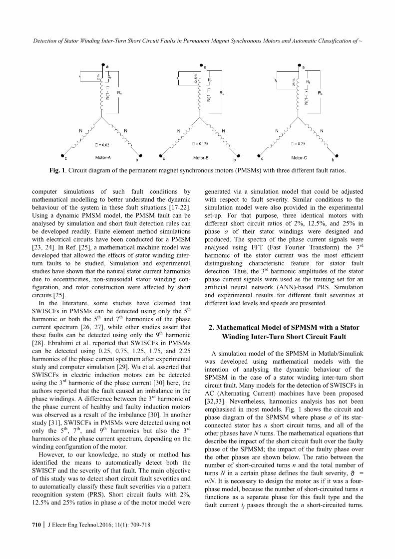
was developed using mathematical models with the intention of analysing the dynamic behaviour of the SPMSM in the case of a stator winding inter-turn short circuit fault. Many models for the detection of SWISCFs in AC (Alternating Current) machines have been proposed [32,33]. Nevertheless, harmonics analysis has not been emphasised in most models. Fig. 1 shows the circuit and phase diagram of the SPMSM where phase a of its star-connected stator has n short circuit turns, and all of the other phases have N turns. The mathematical equations that describe the impact of the short circuit fault over the faulty phase of the SPMSM; the impact of the faulty phase over the other phases are shown below. The ratio between the number of short-circuited turns n and the total number of turns N in a certain phase defines the fault severity, ϑ = n/N. It is necessary to design the motor as if it was a four-phase model, because the number of short-circuited turns n functions as a separate phase for this fault type and the fault current if passes through the n short-circuited turns.
Fig. 1. Circuit diagram of the permanent magnet synchronous motors (PMSMs) with three different fault ratios.
Ferhat CIRA, Muslum ARKAN and Bilal GUMUS
http://www.jeet.or.kr │ 711
Resistance, represented as Rf, which models the insulation fault, also occurs in the short circuited turn [26]. In addition to this, the Rf value depends on the fault severity. Lower values of Rf indicate a more severe inter-turn short-circuit fault condition. The three-phase (abc) state-space equations of voltages of the healthy SPMSM can be written as
, , ,.s abc sh s abc s abcddt
= +V R i λ (1)
In Eq. (1), Vs, is, λs, and Rsh represent the stator three-
phase voltage matrix, the stator phase currents, the stator three-phase magnetic flux matrix, and the stator winding resistance matrix of the healthy motor, respectively.
The stator phase voltage and current matrices are represented as t
, = [ ]s abc a b cV V VV and , [ ]ts abc a b ci i i=i .
The stator winding resistance matrix is0 0
0 00 0
s
sh s
s
RR
R
⎡ ⎤⎢ ⎥= ⎢ ⎥⎢ ⎥⎣ ⎦
R .
The stator three phase magnetic flux matrix is expressed as follows:
s,abc = sh s,abc PM,abc. +λ L i λ (2)
In this equation, sh
L M MM L MM M L
⎡ ⎤⎢ ⎥= ⎢ ⎥⎢ ⎥⎣ ⎦
L is the inductance
matrix and λPM represents the fundamental magnet flux of a healthy SPMSM.
,2 2.[cos cos( ) cos( )]3 3
tPM abc PM
π πθ θ θ= − +λ λ (3)
Eq. (4) is derived by substituting the flux expression in
Eq. (1).
s,abc sh s,abc sh s,abc PM,abcd d= . + . +dt dt
V R i L i λ (4)
The state space equations of the SPMSM, which have a
SWISCF in the three phase abc reference frame, can be written as
sf,abc sf sf,abc sf,abc 0d= . + +dt
V R i λ V (5)
sf,abc sf sf,abc PMf,abc= . +λ L i λ (6)
In these equations, the stator phase voltage matrix of the faulty motor is t[ ]sf,abc a b c= V V V 0V , the stator phase
current matrix of the faulty motor is t[ ]sf,abc a b c f= i i i ii ,
the stator winding resistances matrix of the faulty motor is 0 0 0
0 00 0 00 0
S
S Ssf
S
S S f
kRR R
RR R R
ϑ
ϑ ϑ
⎡ ⎤⎢ ⎥−
= ⎢ ⎥⎢ ⎥
− −⎢ ⎥⎣ ⎦
R the stator flux matrix of
the faulty motor is ,
PMa
PMbsf abc
PMc
PMf
λλλλ
⎡ ⎤⎢ ⎥⎢ ⎥=⎢ ⎥⎢ ⎥⎢ ⎥⎣ ⎦
λ , the stator inductance
matrix of the faulty motor is
2
sf
L M M MM L M LM M L MM M M L
ϑϑϑ
ϑ ϑ ϑ ϑ
−⎡ ⎤⎢ ⎥−⎢ ⎥=⎢ ⎥−⎢ ⎥
−⎣ ⎦
L ,
and the zero-sequence voltage matrix of the faulty motor is 0 0[1 1 1 0] .t V=V The expanded forms of these matrices
are given below:
t[cos( ) cos( ) cos( )]PMf,abc PM2π 2π= λ . θ θ - θ+3 3
λ (7)
The voltage V0 can be expressed as follows [25]:
0
,0
1 1 1( ) (k 1)3 3 3
1 ( 2 )3
a b c S a S f
fPM
V V V R i R i
di dL Mdt dt
ϑ λ
ϑ= + + − − +
+ + −
V (8)
In this equation, k=Rf /Rs ; the average permanent magnet
flux is represented as λPM,0 , calculated as follows:
,0 , , ,1 ( )3PM PM a PM b PM cλ λ λ= + +λ (9)
Given the three-phase abc reference frame of the
SPMSM, the dq reference frame of the motor was derived using Park’s transformation. Speed control was applied in this way because the vector-controlled model of the SPMSM was used in the simulation. The dq reference frame is fixed to the rotor, with the positive d-axis aligned with the magnet flux vector. The positive q-axis is defined as leading the positive d-axis by π/2. Park’s transform allows converting magnitudes from the three-phase abc reference frame to the rotor-fixed dq frame using Fdq0f = Tdq0f・Fabcf, with Tdq0f being the Park transformation matrix. The inverse of Park’s transformation allows converting magnitudes from the rotor-fixed dq reference frame to the three-phase abc reference frame. The inverse transformation is given by Fabcf = Tdq0f
-1・Fdq0f, with Tdq0f-1
being the inverse of Park’s transformation matrix. Equations (10) and (11) show adaptations of these matrices to accommodate faulty conditions; healthy and faulty models of the motor were generated, respectively.
Detection of Stator Winding Inter-Turn Short Circuit Faults in Permanent Magnet Synchronous Motors and Automatic Classification of ~
712 │ J Electr Eng Technol.2016; 11(1): 709-718
0
2 2cos( ) cos( ) cos( ) cos( )3 3
2 2sin( ) sin( ) sin( ) sin( )23 3
3 1 1 1 02 2 20 0 0 1
qd f
π πθ θ θ θ
π πθ θ θ θ
⎡ ⎤− +⎢ ⎥⎢ ⎥⎢ ⎥− +⎢ ⎥=⎢ ⎥⎢ ⎥⎢ ⎥⎢ ⎥⎣ ⎦
T
00
a q
b dqd f
c
f f
I II I
xI II I
⎡ ⎤ ⎡ ⎤⎢ ⎥ ⎢ ⎥⎢ ⎥ ⎢ ⎥⇒ =⎢ ⎥ ⎢ ⎥⎢ ⎥ ⎢ ⎥⎢ ⎥ ⎢ ⎥⎣ ⎦ ⎣ ⎦
T
(10)
10
10
0
cos( ) sin( ) 1 12 2 1cos( ) sin( ) 13 3 2
2 2 1cos( ) sin( ) 13 3 2
30 0 02
qd f
q a
d bqd f
c
f f
I II I
xI II I
θ θπ πθ θ
π πθ θ−
−
−⎡ ⎤⎢ ⎥⎢ ⎥− −⎢ ⎥⎢ ⎥=⎢ ⎥+ +⎢ ⎥⎢ ⎥⎢ ⎥⎣ ⎦
⎡ ⎤ ⎡ ⎤⎢ ⎥ ⎢ ⎥⎢ ⎥ ⎢ ⎥⇒ =⎢ ⎥ ⎢ ⎥⎢ ⎥ ⎢ ⎥⎢ ⎥ ⎢ ⎥⎣ ⎦ ⎣ ⎦
T
T
(11)
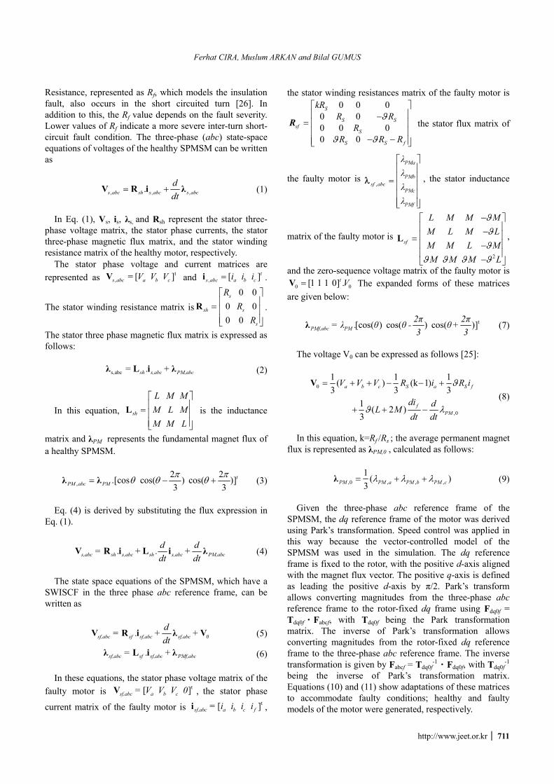
Fig. 2 shows the simulation model generated in
Matlab/Simulink. In this model, the current data of three faulty SPMSMs, each with a different short circuit ratio (2%, 12.5%, and 25%) and a healthy one, were acquired under various speed and load conditions; the spectra of these data were analysed using FFT. Both 100 healthy and 100 faulty current data were recorded from phase a with 25%, 50%, 75%, 100%, and 110% load ratios at a 6-kHz sampling frequency for 2 s from 600 to 2000 rpm via a
vector-controlled SPMSM drive. Thus, all of the current harmonic components, up to a frequency of 3 kHz, were observed at 0.5-Hz resolution. Under faulty conditions, the amplitude of the 3rd harmonic of the current increased as the severity of the fault increased. Also, the amplitude of the 3rd harmonic current signal was close to zero for the healthy case. The simulation results showed that by analysing changes in the 3rd harmonic of the stator phase current, a stator short circuit fault in the SPMSM could be detected.
A report in the literature previously asserted that change can be observed in the 3rd harmonic of the current spectrum in the condition of a stator winding inter-turn short circuit phase fault in a SPMSM, depending on the winding configuration [31]. However, there has been no reported study of the use of an automatic pattern recognition system (PRS) to take advantage of the amplitude of the 3rd harmonic of the stator phase current to detect fault existence and severity. In [31], the authors claimed that the 3rd harmonic of the phase current could be used to detect a fault for a specified speed under a fixed load. Current study showed that the amplitude of the 3rd harmonic of the stator phase current was the most deterministic feature for detecting a fault over a broad range of speeds and loads. Detecting faults, not by looking at current spectra but through automatic computer algorithms, provides a great advantage to users.
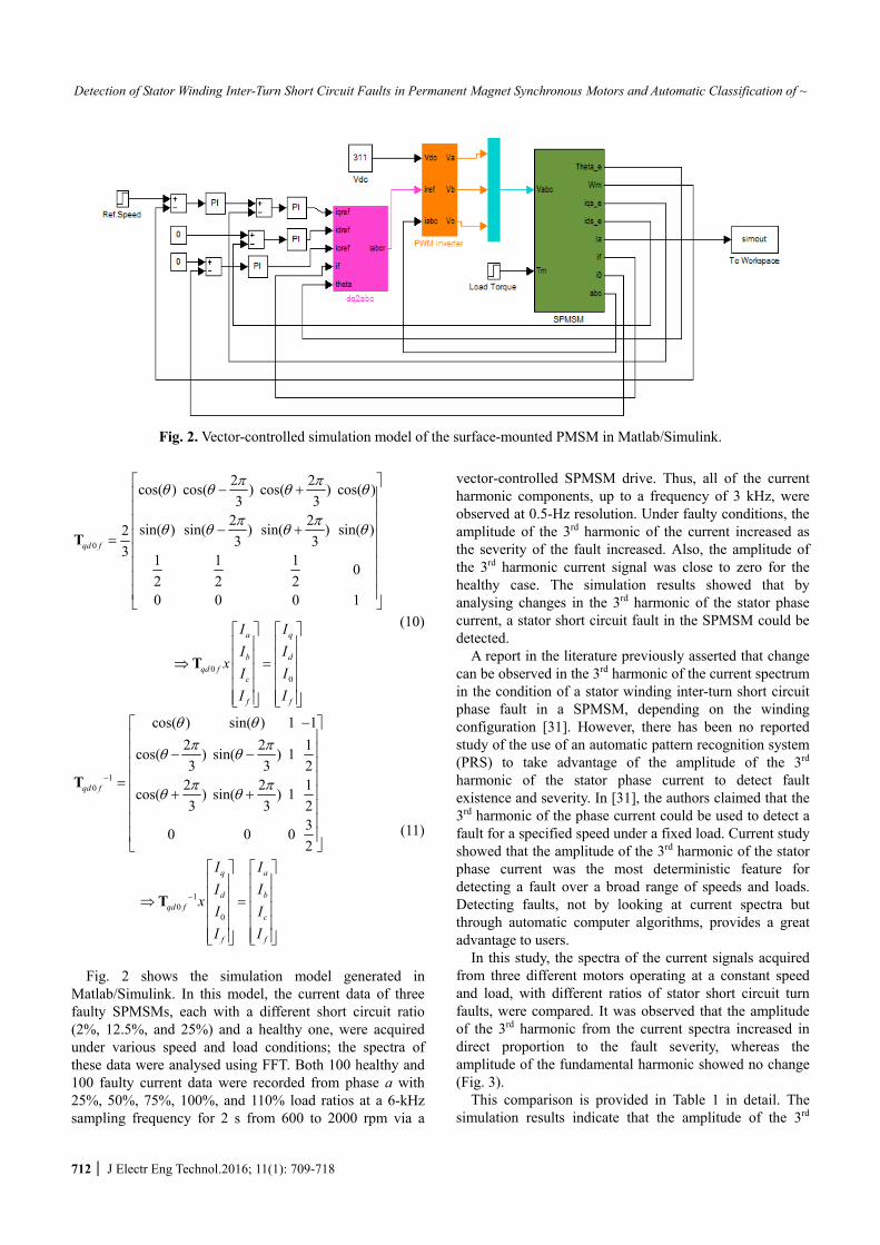
In this study, the spectra of the current signals acquired from three different motors operating at a constant speed and load, with different ratios of stator short circuit turn faults, were compared. It was observed that the amplitude of the 3rd harmonic from the current spectra increased in direct proportion to the fault severity, whereas the amplitude of the fundamental harmonic showed no change (Fig. 3).
This comparison is provided in Table 1 in detail. The simulation results indicate that the amplitude of the 3rd
Fig. 2. Vector-controlled simulation model of the surface-mounted PMSM in Matlab/Simulink.
Ferhat CIRA, Muslum ARKAN and Bilal GUMUS
http://www.jeet.or.kr │ 713
harmonic of the current is the most deterministic feature for detecting the existence and severity of the fault. Thus, not only the fault’s existence but also the fault’s severity can be detected automatically.
3. Experimental Detection of a Stator Winding
Inter-Turn Short Circuit Fault in a SPMSM In the previous section, the data acquired by the
generated simulation model showed that the detection of the SWISCF can be performed using the stator phase current spectrum. In this section, fault detection was performed by comparing the faulty phase currents from a motor whose fault severity was known with the phase currents of a healthy equivalent of the same motors. The experimental set-up for the detection of SWISCF in a SPMSM and the results of this set-up have been explained. Three identical three-phase, 3-Nm/1-kW SPMSMs with 280 turns were fabricated with short circuit ratios of 2, 12.5, and 25%. The motors were designed such that both healthy and faulty signals could be acquired depending on the configuration. LA 55-P model current transducers were
used for current measurements. Real-time stator current data were acquired and recorded using the analogue input ports of the NI 6341 DAQ system at 6 kHz.
SPMSM stator phase currents were recorded at a 6-kHz sampling frequency during 12 s in the range of 600–2000 rpm speed for unloaded, 25% loaded, half loaded, fully loaded, and overloaded cases.
In total, 198 current signals, 99 healthy and 99 faulty ones, were recorded from phase a, starting with the motor that has a short circuit ratio of 25%. Because the short circuit fault rate is high, the need for additional signal recording did not arise. Second, 260 signals, 130 healthy and 130 faulty ones, were recorded from a motor with a short circuit ratio of 12.5%. Finally, 316 signals, 158 healthy and 158 faulty ones, were recorded from the motor with the lowest short circuit ratio of 2%. It is important, in terms of increasing sensitivity and accuracy, to record a greater number of signals, because it is harder to detect faults as the short circuit ratio decreases. All of the recorded signals were processed and saved into files via a program written in Matlab.
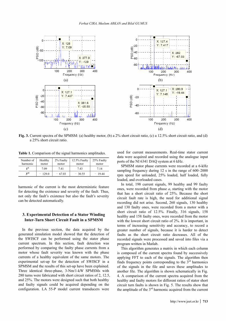
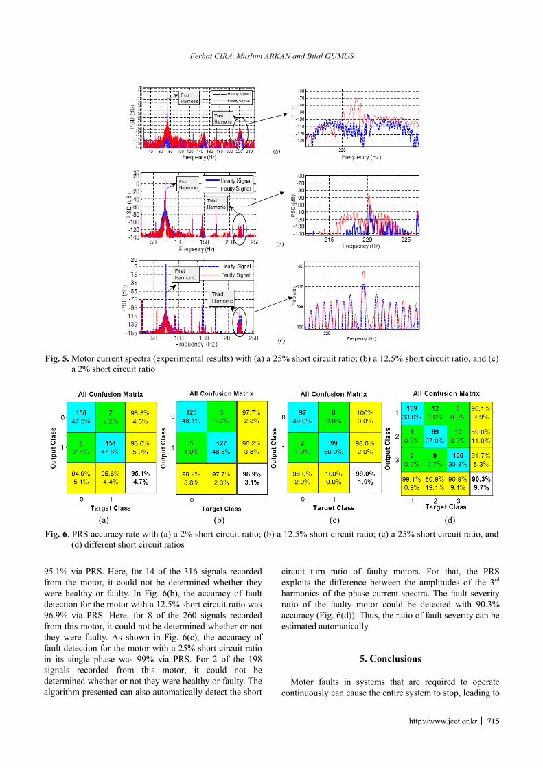
This algorithm generates a matrix in which each column is composed of the current spectra found by successively applying FFT to each of the signals. The algorithm then finds frequency points corresponding to the 3rd harmonics of the signals in the file and saves these amplitudes to another file. The algorithm is shown schematically in Fig. 4. A comparison of the current spectra acquired from the healthy and faulty motors for different ratios of stator short circuit turn faults is shown in Fig. 5. The results show that the amplitude of the 3rd harmonic acquired from the current
(a)
(b)
(c)
(d)
Fig. 3. Current spectra of the SPMSM: (a) healthy motor, (b) a 2% short circuit ratio, (c) a 12.5% short circuit ratio, and (d) a 25% short circuit ratio.
Table 1. Comparison of the signal harmonics amplitudes.
Number of harmonic
Healthy motor
2% Faultymotor
12.5% Faulty motor
25% Faultymotor
1st 7.09 7.41 7.43 7.14
3rd − 129.0 − 67.03 − 30.55 − 19.44
Detection of Stator Winding Inter-Turn Short Circuit Faults in Permanent Magnet Synchronous Motors and Automatic Classification of ~
714 │ J Electr Eng Technol.2016; 11(1): 709-718
spectrum increases in direct proportion to the fault severity. This comparison is given in Table 2 in detail.
4. Detection of a Stator Winding Inter-Turn Short Circuit Fault of a SPMSM and Automatic
Classification of Fault Severity via PRS Pattern recognition is involved in a wide range of
activities in fields such as science, engineering, and daily life. The essence of human pattern recognition is learning based on previous experiences. Thus, people have the ability to evaluate pattern recognition events that they encounter in practice with the help of their experiences. People desire that the machines carry out these tasks better, more cheaply, more quickly, and automatically even if people can perform most of these tasks very well. Pattern recognition is a multidimensional engineering discipline to realise ‘smart’ machines that can learn [34]. The pattern recognition concept can be defined as to identify or classify complex signal samples or objects that have common features among them and can be associated with each other via some determined features or characteristics. In this respect, the most important aims of pattern recognition are
modelling unknown pattern classes and diagnosing a pattern belonging to a known class [34].
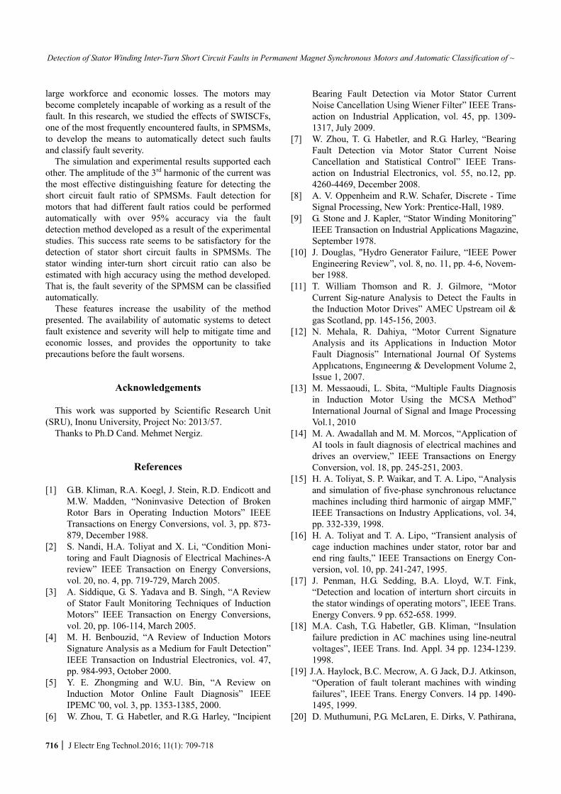
The PRS consists of three basic steps: feature extraction, feature selection, and classification. The feature extraction step is the process in which a variety of transformation techniques are used to extract features that characterise the raw pattern acquired via electronic sensors. The feature selection step is a process in which the most characteristic features are determined after feature extraction. The classification step is the process by which the class of the pattern is determined using the features selected at the end of the feature selection step with the help of a classifier. An ANN-based PRS has been used to detect the existence of faults and the level of fault severity. In this system, the amplitude of the 3rd harmonic was determined as the distinguishing feature of the signal and was applied to the ANN as an input. The scaled conjugate gradient method was used as the training function and 80%, 10%, and 10% of the current data that were recorded from the motors with different short circuit ratios were used for training, testing, and validation, respectively. The ANN was composed of 20 hidden layers to determine the accuracy ratio of faulty signal classification. One measure of how well a neural network fits the data is the confusion plot. Fig. 6 shows a confusion matrix plot of the percentages of correct and incorrect classifications for the samples. Correct classifications correspond to the light blue squares on the matrix diagonal; incorrect classifications are indicated by the green squares.
The matrix also shows the accuracy of the classifier as the percentage of correctly classified patterns in a given class divided by the total number of patterns in that class. The overall (average) accuracy of the classifier is also evaluated using the confusion matrix.
In Fig. 6(a), the accuracy of fault detection for the motor that had a 2% short circuit ratio in its single phase was
Fig. 4. Schematic drawing of the experimental setup for the automatic detection of faults and the classification of fault
severity.
Table 2. Comparison of amplitudes of healthy and faulty signals with different short circuit ratios.
Short-circuit fault ratio Motor A Motor B Motor C
(2%) (12.5%) (25%) Healthy condition − 113.05 − 99.93 − 106.0 Faulty condition
− 100.1 − 82.88 − 67.77
Difference 12.90 17.05 38.63
Ferhat CIRA, Muslum ARKAN and Bilal GUMUS
http://www.jeet.or.kr │ 715
95.1% via PRS. Here, for 14 of the 316 signals recorded from the motor, it could not be determined whether they were healthy or faulty. In Fig. 6(b), the accuracy of fault detection for the motor with a 12.5% short circuit ratio was 96.9% via PRS. Here, for 8 of the 260 signals recorded from this motor, it could not be determined whether or not they were faulty. As shown in Fig. 6(c), the accuracy of fault detection for the motor with a 25% short circuit ratio in its single phase was 99% via PRS. For 2 of the 198 signals recorded from this motor, it could not be determined whether or not they were healthy or faulty. The algorithm presented can also automatically detect the short
circuit turn ratio of faulty motors. For that, the PRS exploits the difference between the amplitudes of the 3rd harmonics of the phase current spectra. The fault severity ratio of the faulty motor could be detected with 90.3% accuracy (Fig. 6(d)). Thus, the ratio of fault severity can be estimated automatically.
5. Conclusions Motor faults in systems that are required to operate
continuously can cause the entire system to stop, leading to
Fig. 5. Motor current spectra (experimental results) with (a) a 25% short circuit ratio; (b) a 12.5% short circuit ratio, and (c)
a 2% short circuit ratio
(a) (b) (c) (d) Fig. 6. PRS accuracy rate with (a) a 2% short circuit ratio; (b) a 12.5% short circuit ratio; (c) a 25% short circuit ratio, and
(d) different short circuit ratios
Detection of Stator Winding Inter-Turn Short Circuit Faults in Permanent Magnet Synchronous Motors and Automatic Classification of ~
716 │ J Electr Eng Technol.2016; 11(1): 709-718
large workforce and economic losses. The motors may become completely incapable of working as a result of the fault. In this research, we studied the effects of SWISCFs, one of the most frequently encountered faults, in SPMSMs, to develop the means to automatically detect such faults and classify fault severity.
The simulation and experimental results supported each other. The amplitude of the 3rd harmonic of the current was the most effective distinguishing feature for detecting the short circuit fault ratio of SPMSMs. Fault detection for motors that had different fault ratios could be performed automatically with over 95% accuracy via the fault detection method developed as a result of the experimental studies. This success rate seems to be satisfactory for the detection of stator short circuit faults in SPMSMs. The stator winding inter-turn short circuit ratio can also be estimated with high accuracy using the method developed. That is, the fault severity of the SPMSM can be classified automatically.
These features increase the usability of the method presented. The availability of automatic systems to detect fault existence and severity will help to mitigate time and economic losses, and provides the opportunity to take precautions before the fault worsens.
Acknowledgements This work was supported by Scientific Research Unit
(SRU), Inonu University, Project No: 2013/57. Thanks to Ph.D Cand. Mehmet Nergiz.
References
[1] G.B. Kliman, R.A. Koegl, J. Stein, R.D. Endicott and M.W. Madden, “Noninvasive Detection of Broken Rotor Bars in Operating Induction Motors” IEEE Transactions on Energy Conversions, vol. 3, pp. 873-879, December 1988.
[2] S. Nandi, H.A. Toliyat and X. Li, “Condition Moni-toring and Fault Diagnosis of Electrical Machines-A review” IEEE Transaction on Energy Conversions, vol. 20, no. 4, pp. 719-729, March 2005.
[3] A. Siddique, G. S. Yadava and B. Singh, “A Review of Stator Fault Monitoring Techniques of Induction Motors” IEEE Transaction on Energy Conversions, vol. 20, pp. 106-114, March 2005.
[4] M. H. Benbouzid, “A Review of Induction Motors Signature Analysis as a Medium for Fault Detection” IEEE Transaction on Industrial Electronics, vol. 47, pp. 984-993, October 2000.
[5] Y. E. Zhongming and W.U. Bin, “A Review on Induction Motor Online Fault Diagnosis” IEEE IPEMC '00, vol. 3, pp. 1353-1385, 2000.
[6] W. Zhou, T. G. Habetler, and R.G. Harley, “Incipient
Bearing Fault Detection via Motor Stator Current Noise Cancellation Using Wiener Filter” IEEE Trans-action on Industrial Application, vol. 45, pp. 1309-1317, July 2009.
[7] W. Zhou, T. G. Habetler, and R.G. Harley, “Bearing Fault Detection via Motor Stator Current Noise Cancellation and Statistical Control” IEEE Trans-action on Industrial Electronics, vol. 55, no.12, pp. 4260-4469, December 2008.
[8] A. V. Oppenheim and R.W. Schafer, Discrete - Time Signal Processing, New York: Prentice-Hall, 1989.
[9] G. Stone and J. Kapler, “Stator Winding Monitoring” IEEE Transaction on Industrial Applications Magazine, September 1978.
[10] J. Douglas, "Hydro Generator Failure, “IEEE Power Engineering Review”, vol. 8, no. 11, pp. 4-6, Novem-ber 1988.
[11] T. William Thomson and R. J. Gilmore, “Motor Current Sig-nature Analysis to Detect the Faults in the Induction Motor Drives” AMEC Upstream oil & gas Scotland, pp. 145-156, 2003.
[12] N. Mehala, R. Dahiya, “Motor Current Signature Analysis and its Applications in Induction Motor Fault Diagnosis” International Journal Of Systems Applıcatıons, Engıneerıng & Development Volume 2, Issue 1, 2007.
[13] M. Messaoudi, L. Sbita, “Multiple Faults Diagnosis in Induction Motor Using the MCSA Method” International Journal of Signal and Image Processing Vol.1, 2010
[14] M. A. Awadallah and M. M. Morcos, “Application of AI tools in fault diagnosis of electrical machines and drives an overview,” IEEE Transactions on Energy Conversion, vol. 18, pp. 245-251, 2003.
[15] H. A. Toliyat, S. P. Waikar, and T. A. Lipo, “Analysis and simulation of five-phase synchronous reluctance machines including third harmonic of airgap MMF,” IEEE Transactions on Industry Applications, vol. 34, pp. 332-339, 1998.
[16] H. A. Toliyat and T. A. Lipo, “Transient analysis of cage induction machines under stator, rotor bar and end ring faults,” IEEE Transactions on Energy Con-version, vol. 10, pp. 241-247, 1995.
[17] J. Penman, H.G. Sedding, B.A. Lloyd, W.T. Fink, “Detection and location of interturn short circuits in the stator windings of operating motors”, IEEE Trans. Energy Convers. 9 pp. 652-658. 1999.
[18] M.A. Cash, T.G. Habetler, G.B. Kliman, “Insulation failure prediction in AC machines using line-neutral voltages”, IEEE Trans. Ind. Appl. 34 pp. 1234-1239. 1998.
[19] J.A. Haylock, B.C. Mecrow, A. G Jack, D.J. Atkinson, “Operation of fault tolerant machines with winding failures”, IEEE Trans. Energy Convers. 14 pp. 1490-1495, 1999.
[20] D. Muthumuni, P.G. McLaren, E. Dirks, V. Pathirana,
Ferhat CIRA, Muslum ARKAN and Bilal GUMUS
http://www.jeet.or.kr │ 717
“A synchronous machine model to analyze internal faults”, in: Conference Record Ind. Appl. Conference, 36th IAS Annual Meeting, vol. 3, pp. 1595-1600, 2001.
[21] S.M. Halpin, C.A. Gross, “Time domain solutions for faulted power systems using detailed synchronous machine models”, in: 22nd Southeastern Symposium on System Theory, pp. 607-611, March 1990.
[22] D.L. Brooks, S.M. Halpin, “An improved fault analysis algorithm including detailed synchronous machine models and magnetic saturation”, J. Electr. Power Syst. Res. 42, pp. 3-9, 1997.
[23] B.G. Gu, J.H. Choi and I.S. Jung, “Development and Analysis of Interturn Short Fault Model of PMSMs With Series and Parallel Winding Connections” IEEE Transactions On Power Electronics, Vol. 29, No. 4, April 2014.
[24] J.H. Choi, B.G. Gu and C.Y. Won, “Modeling and Analysis of PMSMs under Inter Turn Short Faults” J Electr Eng Technol Vol. 8, pp. 1243-1250, 2013.
[25] L. Romeral, J. C. Urresty, J. R. Riba Ruiz, and A. Garcia Espinosa, “Modeling of Surface-Mounted Permanent Magnet Synchronous Motors With Stator Winding Interturn Faults,” IEEE Transactions on Industrial Electronics,, vol. 58, pp. 1576- 1585, 2011.
[26] J.C. Urresty, J.R. Riba, L. Romeral, “Application of the zero-sequence voltage component to detect stator winding inter-turn faults in PMSMs”, Electric Power Systems Research, pp. 38-44, 2012.
[27] J. Urresty, J. Riba, L. Romeral, J. Rosero, J. Serna, “Stator Short Circuits Detection in PMSM by means of Hilbert-Huang transform and energy calculation, Diagnostics for Electric Machines, Power Electronics and Drives”, SDEMPED IEEE International Sym-posium on August-Sept. 2009.
[28] J. Rosero, J. Romeral, “Simulation and Fault De-tection in PMSM under Dynamic Conditions”, Cedrat Flux Solutions & Mechatronic Products, vol. 57, January 2009.
[29] B. M. Ebrahimi, J. Faiz, “Feature Extraction for Short-Circuit Fault Detection in Permanent-Magnet Synchronous Motors Using Stator-Current Moni-toring”, IEEE Transaction on Power Electronics, Vol. 25, No. 10, October 2010.
[30] Q. Wu, S. Nandi, “Fast Single-Turn Sensitive Stator winding inter-turn Fault Detection of Induction Machines Based on Positive- and Negative-Sequence Third Harmonic Components of Line Currents”, IEEE Transactions on Industry Applications, Vol. 46, No. 3, May/June 2010.
[31] H. Saavedra, J. C. Urresty, J. R. Riba, L. Romeral, “Detection of interturn faults in PMSMs with di-fferent winding configurations”, Energy Conversion and Management, pp. 534-542, 2014
[32] T. R. Jawad A. Farooq, A. Djerdir, A. Miraoui, “Modelling and simulation of stator winding inter-
turn faults in permanent magnet synchronous motors,” The International Journal for Computation and Mathematics in Electrical and Electronic Engineering, vol. 27, pp. 9, 2008.
[33] R. M. Tallam, T. G. Habetler, and R. G. Harley, “Transient model for induction machines with stator winding turn faults,” Industry Applications, IEEE Transactions on, vol. 38, pp. 632-637, 2002.
[34] Turkoğlu, İ., “An Intelligent pattern recognition for nonstationary signals based on the time-frequency entropies”, PhD Thesis, Elazığ, Turkey, 2002.
Ferhat CIRA received M.Sc. degree in Electrical and Electronics Engi-neering from Dicle University, Diyarbakır, Turkey, in 2010. Now, he works as research assistant in Dicle University and also currently working toward the Ph.D degree in Electrical and Electronics Engineering at Inonu
University, Turkey. His research interests are in the field of electric machines drives and condition monitoring and diagnostic techniques.
Muslum ARKAN received B.Sc. degree in Electrical and Electronics Engineering from University of Gaziantep, Gaziantep, Turkey, and his DPhil degree in Electrical Engineering from University of Sussex, Brighton, UK, in 1994 and 2000 respectively. Since 1994, he has been with the
Electrical and Electronics Engineering Department, Inonu University, Malatya, Turkey, where he is currently an Associate Professor. His research activities include the use of digital signal analysis for diagnostic, condition moni-toring and motor failure prediction by sensorless methods and modeling of electrical machines for diagnosis purpose.
Bilal GUMUS recieved M.Sc. and PhD in 1997 - 2004 respectively at Fırat University Engineering Faculty Department of Electrical and Elec-tronics Engineering. He is currently working as assistant professor for Dicle Üniversity. His research interests are electrical machines, power elec-tronics, energy systems and renewable
energy sources.