Embed Size (px)
Citation preview

Detectors for a Linear Collider
1
Joachim MnichDESY
Vienna, February 22nd, 2007
VC
I 200
7, F
ebru
ary
19 –
24, 2
007

Outline
The International Linear Collider (ILC)Status of the projectPhysics motivationImpact on detector designThe four detector concepts
Detector R&D for key componentsVertex detectorsTrackingCalorimetryTowards lager prototypes
Conclusions & Outlook
2
VC
I200
7, F
ebru
ary
19-2
4, 2
007

The International Linear ColliderElectron-positron collider
centre-of-mass energy up to 1 TeV centre-of-mass energyluminosities > 1034/cm2/s
The next large High Energy Physics project (after the LHC)
Designed in a global effort
Accelerator technology: supra-conducting RF cavities
Elements of a linear collider:
3
VC
I200
7, F
ebru
ary
19-2
4, 2
007
main linacbunchcompressor
dampingring
source
pre-accelerator
collimation
final focus
IP
extraction& dump
KeV
few GeV
few GeVfew GeV
250-500 GeV
The International Linear ColliderInternational organisation:
Global Design Effort (GDE), started in 2005 Chair: Barry Barishrepresenatives from Americas, Asia and Europeall major laboratories and many people contributing
4
VC
I200
7, F
ebru
ary
19-2
4, 2
007

The International Linear Collider2006: Baseline Configuration Document February 2007:
Reference Design Report presented at Beijing ACFA ILC MeetingLayout of the machine:
5
VC
I200
7, F
ebru
ary
19-2
4, 2
007
2 × 250 GeVupgradable to 2 × 500 GeV1 interaction region2 detectors (push-pull)14 mrad crossing angle
Cost estimate:4.87 G$ shared components
+ 1.78 G$ site-dependent= 6.65 G$ (= 5.52 G€)
+ 13000 person years

ILC Physics MotivationILC will complement LHC discoveries by precision measurementsHere just two examples:
1) There is a Higgs, observed at the LHCe+e− experiments can detect Higgs bosons without assumption on decay propertiesHiggs-Strahlungs process (à la LEP)
identify Higgs events in e+e− → ZH from Z → µµ decay
count Higgs decay products to measure Higgs BRsand hence (Yukawa)-couplings
6
VC
I200
7, F
ebru
ary
19-2
4, 2
007

ILC Physics MotivationMeasure Higgs self-couplings e+e– → ZHH to establish Higgs potential Note: small signal above large QCD background
2) There is NO Higgs (definite answer from LHC!)
something else must prevent e.g. WW scattering from violating unitarity at O(1 TeV) strong electroweak symmetry breaking?→ study e+ e– → WWνν, Wzeν and ZZee events
need to select and distinguish W and Z bosons in their hadronic decays!BR (W/Z → hadrons) = 68% / 70%
Many other physics cases: SM, SUSY, new phenomena, …
Need ultimate detector performance to meet the ILC physics case7
VC
I200
7, F
ebru
ary
19-2
4, 2
007

Impact on Detector DesignVertex detector:e.g. distinguish c- from b-quarks
goal impact parameter resolution σrφ ≈ σz ≈ 5 ⊕ 10/(p sinΘ3/2) µm 3 times better than SLDsmall, low mass pixel detectors, various technologies under studyO(20×20 µm2)
Tracking:superb momentum resolutionto select clean Higgs samplesideally limited only by ГZ
→ Δ(1/pT) = 5·10-5 /GeV (whole tracking system)3 times better than CMS
Options considered: Large silicon trackers (à la ATLAS/CMS)Time Projection Chamber with ≈ 100 µm point resolution(complemented by Si–strip devices)
8
VC
I200
7, F
ebru
ary
19-2
4, 2
007

Impact on Detector DesignCalorimeter:distinguish W- and Z-bosonsin their hadronic decays
→ 30%/√E jet resolution!
9
VC
I200
7, F
ebru
ary
19-2
4, 2
007
→ Particle Flow or Dual Readout calorimeter
2 times better than ZEUS
WW/ZZ → 4 jets:

Detector Challenges at the ILCBunch timing:- 5 trains per second- 2820 bunches per train
separated by 307 nsno triggerpower pulsingreadout speed
14 mrad crossing angleBackground:
small bunches create beamstrahlung → pairs
10
VC
I200
7, F
ebru
ary
19-2
4, 2
007
backgound not as severe as at LHCbut much more relevant than at LEP
VTX
TPC

Detector ConceptsFour detector concepts are being investigated
GLD (Global Large Detector)LDC (Large Detector Concept)SiD (Silicon Detector)4th concept
Summer 2006: Detector Outline Documents (DOD)evolving documents, detailed description
Summer 2007: Detector Concept Reports (DCR)comprehensive detector descriptions, go along with machine RDR
Prepared by international study groupsO(100 - 300) authors per detector concept
11
VC
I200
7, F
ebru
ary
19-2
4, 2
007

Detector Concepts
12
VC
I200
7, F
ebru
ary
19-2
4, 2
007
GLD- TPC tracking
large radius- particle flow calorimeter- 3 Tesla solenoid- scint. fibre µ detector
LDC- TPC tracking
smaller radius- particle flow calorimeter- 4 Tesla solenoid- µ detection: RPC or others

Detector Concepts
13
VC
I200
7, F
ebru
ary
19-2
4, 2
007
SiD- silicon tracking- smaller radius- high field solenoid (5 Tesla)- scint. fibre / RPC µ detector
Silicon tracker
6.45 m
6.45 m
Magnet- high field- but smaller volume
• CMS

Detector Concepts
14
VC
I200
7, F
ebru
ary
19-2
4, 2
007
4th concept- TPC- multiple Readout Calorimeter- iron-free magnet, dual solenoid- muon spectrometer (drift tubes)
Dual solenoid - iron return yoke replaced
by second barrel coil andcoils at endcap Average field
seen by µ:
<B> ≈ 1.5 T<Bl> ≈ 3 Tm
B
coil

Detector Concept and R&D efforts
R&D efforts for key detector elementsOverlap with detector concepts:
15
VC
I200
7, F
ebru
ary
19-2
4, 2
007
GLD LDC SID 4th concept
Detector R&D collaborations
Vertex X X X X LCFITracking
Calorimetry:
- TPC X X X LCTPC- Silicon * * X * SILC
- Particle Flow X X X CALICE- Multiple Readout X- Forward region X X X X VFCAL
* silicon forward and auxiliary tracking also relevant for other concepts

Vertex DetectorKey issuses:
measure impact parameter for each trackspace point resolution < 5 µmsmallest possible inner radius ri ≈ 15 mmtransparency: ≈ 0.1% X0 per layer
= 100 µm of siliconstand alone tracking capabilityfull coverage |cos Θ| < 0.98modest power consumption < 100 W
Five layers of pixel detectors plus forward disks
pixel size O(20×20 µm2) 109 channels
Note: wrt. the LHC pixel detectors1/5 ri 1/30 pixel size1/30 thickness
16
VC
I200
7, F
ebru
ary
19-2
4, 2
007

Vertex DetectorCritical issue is readout speed:Inner layer can afford O(1) hit per mm2 (pattern recognition)
once per bunch = 300 ns per frame too fastonce per train ≈ 100 hits/mm2 too slow 20 times per train ≈ 5 hits/mm2 might work50 µs per frame of 109 pixels!
→ readout during bunch train (20 times)or store data on chip and readout in between trainse.g. ISIS: In-situ Storage Image Sensor
17
VC
I200
7, F
ebru
ary
19-2
4, 2
007
Many different (sensor)-technologies under studyCPCCD, MAPS, DEPFET, CAPS/FAPS, SOI/3-D, SCCD, FPCCD, Chronopixel, ISIS, …→ Linear Collider Flavour Identification (LCFI) R&D collaborationBelow a few examples
Note: many R&D issues independent of Si-technology (mechanics, cooling, …)

Vertex Detector
18
VC
I200
7, F
ebru
ary
19-2
4, 2
007

CP CCD
CCDcreate signal in 20 µm active layeretching of bulk material to keeptotal thickness ≤ 60 μmlow power consumptionbut very slow
→ apply column parallel (CP) readout
19
VC
I200
7, F
ebru
ary
19-2
4, 2
007
p(Epi)
p+(bulk)
p/p+(edge)
Depletionedge
n layer
Particle trajectory
~20µmactive
x
x
xxxx
x
CCD classic CP CCD
Second generation CP CCDdesigned to reach 50 MHz operation

MAPS and DEPFET
CMOS Monolithic Active Pixel detectors
standard CMOS wafer integratingall functionsno bonding between sensor and electronics
e.g. Mimosa chip
20
VC
I200
7, F
ebru
ary
19-2
4, 2
007
DEPFET: Depleted Field Effect Transistor
fully depleted sensor with integrated pre-amplifierlow power and low noise

Vertex Detector SupportMechanical support structuregoal 0.1% X0 per layer
Example:- Reticulated Vitreous Carbon (RVC) - or Silicon Carbid SiC foams
both good thermal match to Si
1.5 mm RVC foam + 2×25 µm silicon = 0.09% X0
1.5 mm SiC foam + 25 µm silicon= 0.16% X0 (reducible, less dense foam)
achieved
can be adopted to all detector technologies
21
VC
I200
7, F
ebru
ary
19-2
4, 2
007

Silicon Tracking
The SiD tracker:5 barrel layersri = 20 cm ro = 125 cm10 cm segmentation in zshort sensorsmeasure phi only
endcap disks5 double disk per sidemeasure r and phi
22
VC
I200
7, F
ebru
ary
19-2
4, 2
007
critical issue:material budget(support, cooling, readout)goal: 0.8% X0 per layer
0.1 X0

Silicon Tracking
Alternative design: long ladderSilicon tracking for the Linear Collider (SiLC) collaborationfor all-silicon trackeror silicon enveloppe (→TPC)
Development of low noise electronicsamplification & pulse shaping passive coolingexploit low duty cycle
23
VC
I200
7, F
ebru
ary
19-2
4, 2
007
Prototype modules:
3 × CMS
10 × GLAST

Time Projection Chamber
GLD, LDC and 4th: high resolution TPC as main tracker
3 – 4 m diameter≈ 4.5 m lengthlow mass field cage
3%X0 barrel< 30% X0 endcap
≈ 200 points/track≈ 100 µm single point res.
→ Δ(1/pT) = 10-4 /GeV(10 times better than LEP!)
Complemented by Forward Trackingendcap between TPC and ECALSi strip, straw tube, GEM-based, …are considered
TPC development performed inLCTPC collaboration 24
VC
I200
7, F
ebru
ary
19-2
4, 2
007
endcap tracker

Time Projection Chamber
New concept for gas amplicationat end flanges:Replace proportional wires by Micro Pattern Gas Detectors (MPGD)
GEM or MicroMegasfiner dimensionstwo-dimensional symmetry→ no E×B effectsonly fast electron signalintrinsic suppression of ion backdrift
25
VC
I200
7, F
ebru
ary
19-2
4, 2
007
inducecharge
Pads
sense/fieldwires
gatinggrid
track
driftingchargeWires
track
charge
GEMfoil
pad
dritfting
GEM
Micromesh
Insulatingsubstrate
Pillar
Pad planeMultiplicationregion
GEM µMegas

Time Projection Chamber
Principle of MPGD based TPC establishedmany small scale prototype experiments over the last ≈ 5 years
cosmics, testbeammagnetic field
under construction for experiments (MICE, T2K)
26
VC
I200
7, F
ebru
ary
19-2
4, 2
007
Single point resolution O(100 µm)established in - small scale prototypes- high magnetic fields
Example:

Time Projection Chamber
Low mass fieldcagelarge prototype underconstructionusing composite material
27
VC
I200
7, F
ebru
ary
19-2
4, 2
007
Electronicsfew 106 channels on endplate low power to avoid cooling
two development paths:- FADC based on ALICE ALTRO chip- and TDC chips
≈ 1% X0

TPC versus Silicon Tracking
TPC200 space points (3-dim) → continuous tracking, pattern recognitionlow mass easy to achieve (barrel)
Silicon trackingbetter single point resolutionfast detector (bunch identification)
28
VC
I200
7, F
ebru
ary
19-2
4, 2
007
TPC Si tracking

Silicon TPC Readout
Combine MPGD with pixel readout chips2-d readout with- Medipix2 0.25 µm CMOS- 256×256 pixel- 55 ×55 µm2
Medipix (2-d)→ TimePix (3- d)50 - 150 MHz clock to all pixel1st version under test
Will eventually lead to TPC diagnostic modulecluster counting to improve dE/dx 29
VC
I200
7, F
ebru
ary
19-2
4, 2
007
(Micromegas) (GEM)
TimePix layout TimePix + µMegas

CalorimetryThe paradigm of Particle Flow Algortihm (PFA)for optimum jet energy resolution:
try to reconstruct every particlemeasure charged particles in trackermeasure photons in ECALmeasure neutral hadrons in ECAL+HCALuse tracker + calorimeters to tell charged from neutral
Jet resolutionσ = σcharged ⊕ σphotons ⊕ σneutral ⊕ σconfusion
confusion term arises from misassignment, double counting, overlapping clusters, …
minimizing confusion term requires highly granular calorimeterboth ECAL and HCAL
30
VC
I200
7, F
ebru
ary
19-2
4, 2
007 average visible energy in a jet
≈ 60% charged particles≈ 30% photons≈ 10% neutral hadrons

Calorimetry
CALICE collaboration (Calorimeter for the Linear Collider Experiment)> 30 institutes from > 10 countries
performs R&D effort to validate the concept and design calorimeters for ILC experiments
31
VC
I200
7, F
ebru
ary
19-2
4, 2
007
GLD, LDC, SID conceptsbased on PFA calorimeters
ECAL:SiW calorimeter23 X0 depth0.6 X0 – 1.2 X0 long. segmentation5×5 mm2 cellselectronics integrated in detector
Alternative: W + Scintillating strips (GLD)
ECAL slabFE ASICPCB boardSi pads

Calorimetry
HCAL: 2 options under consideration
Analogue Scintillator Tile calorimetermoderately segmented 3×3 cm2
use SiPM for photo detection
Gaseous Digital HCALfiner segmentation 1×1 cm2
binary cell readoutbased on RPC, GEM or µMegasdetectors
32
VC
I200
7, F
ebru
ary
19-2
4, 2
007

CalorimeterCALICE Testbeam at CERN (2006)
33
VC
I200
7, F
ebru
ary
19-2
4, 2
007
ECAL
HCAL
TCMT

Calorimeter
CALICE Testbeam at CERN (2006)
34
VC
I200
7, F
ebru
ary
19-2
4, 2
007
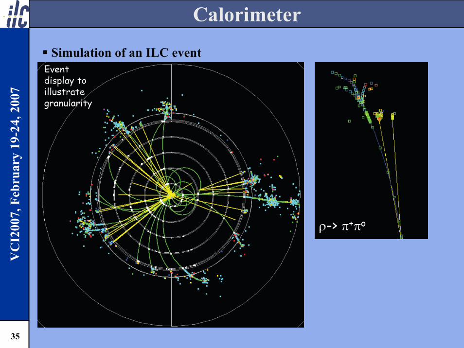
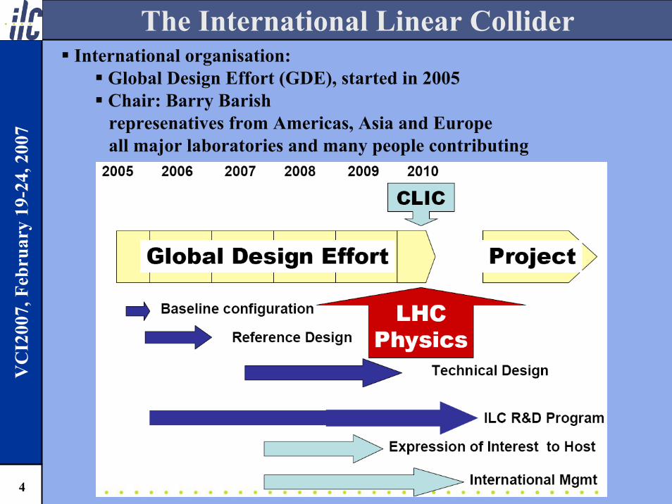
Calorimeter
Simulation of an ILC event
35
VC
I200
7, F
ebru
ary
19-2
4, 2
007

Dual Readout Calorimeter
4th conceptcalorimetry based on dual/triple readout approachcomplementary measurements of showers reduce fluctuactions
36
VC
I200
7, F
ebru
ary
19-2
4, 2
007
Fluctuations of local energy deposits concept
Fluctuations in electromagnetic fraction of shower energy
Binding energy lossesfrom nuclear break-up
Fine spatial samplingwith SciFi every 2mm
clear fibres measure onlyEM component by Cerenkov light of electrons(Eth = 0.25 MeV)
try to measure MeV neutroncomponent of shower(history or Li/B loaded fibres)
like SPACAL (H1)
like HF (CMS)
triple readout
Dual Readout Module (DREAM) in testbeam at CERN

Dual Readout Calorimeter
DREAM testbeam:- measure each shower twice
37
VC
I200
7, F
ebru
ary
19-2
4, 2
007
200 GeV π− beam at CERN
raw data
using C and S
incl. leakage correction(using EB)

Dual Readout Calorimeter
From DREAM to an ILC calorimeter:
38
VC
I200
7, F
ebru
ary
19-2
4, 2
007

Forward CalorimetryForward calorimeters needed
LumCal: precise luminosity measurementprecision < 10-3, i.e. comparable to LEP or better
BeamCal: beam diagnostics & luminosity optimisation
39
VC
I200
7, F
ebru
ary
19-2
4, 2
007
LumiCal
BeamCal
TPC
ECAL
HCAL
Detector technology: tungsten/sensor sandwichExample: LDC design for zero cross angle
to be adapted for 14 mrad ILC design

BeamCal
Challenges:≈ 15000 e+e− pairs per BXin MeV range, extends to GeVtotal deposit O(10 TeV)/BX≈ 10 MGy yearly rad. dose
identification of single high energy electronsto veto two-photon bkgd.
Requires:rad. hard sensors (diamond)high linearity & dynamic rangefast readout (307 ns BX interval)compactness and granularity
40
VC
I200
7, F
ebru
ary
19-2
4, 2
007
Energy deposit per BX:
Electron ID efficiency:

Forward CalorimetrySensors tests at DALINAC (Darmstadt)
current 1 – 100 nA (10 nA ≈ kGy/h)
41
VC
I200
7, F
ebru
ary
19-2
4, 2
007
Diamond sensor after ≈ 7 MGy
10 MeV
Alternative sensor materialsGaAs SiCradiation hard silicon
MIP
sign
al

Muon Detectors
GLD, LDC & SiD have muon detection only: RPC, scint. fibre detectormomentum in central tracker4th concept:
muon spectrometer between coilshigh precision drift tubes
42
VC
I200
7, F
ebru
ary
19-2
4, 2
007
low pT-threshold for muonsexcellent π/µ separationalso exploiting multiple readout calorimeter

Detector Performance
Disclaimer:all in early design phasecomparison difficultassume that R&D is succesful and large scale detectors will keep performance
A few DOD plots on performance from simulation studies
43
VC
I200
7, F
ebru
ary
19-2
4, 2
007
4th concept:- muon spectrometerσ(1/pT) ≈ 4 ·10-4 /GeV

Detector Performance
SiD Tracking:
44
VC
I200
7, F
ebru
ary
19-2
4, 2
007 143 GeV selectron at 1 TeV
mass measurement from end point - 0.1% beam energy spread - 100 MeV error
not limited by tracker
Δm/M
eV
100
40
0.1%
Energy spreadGLD calorimetry:test of PFA with Z-pole eventsZ → hadrons
38% mass resolutionimprovements are still possible

Detector R&D in Europe
Next step:from small scale proof-of-principle experimentsto larger scale prototypes
Example: the EUDET programme in Europe
improvements of infrastructures for larger scale detector prototypes(not only ILC)devised in close cooperation with the international R&D collaborations
Transnational Access:support for (European) groups
DESY testbeamusage of EUDET infrastructures
More information at www.eudet.org45
VC
I200
7, F
ebru
ary
19-2
4, 2
007

EUDET
Network Transnational Access Joint Research Activities
Management
Detector R&D Network
Access to DESY Test Beam
Access to Detector R&D Infrastructures
Test Beam Infrastructures
Tracking Detectors
Calorimeter
European infrastrucutre projects are based on three pilars:
Detector R&D in Europe
46
VC
I200
7, F
ebru
ary
19-2
4, 2
007
Detector R&D Network:Information exchange and intensified collaborationCommon simulation and analysis frameworkValidation of simulationDeep submicron radiation-tolerant electronics
Test Beam Infrastructure:Large bore magnetPixel beam telescope
Tracking Detectors:Large TPC prototypeSilicon TPC readoutSilicon tracking
Calorimeter:ECALHCAL Very Forward CalorimeterFE Electronics and DataAcquistion System
Activities split up into several tasks:

EUDET
47
VC
I200
7, F
ebru
ary
19-2
4, 2
007

Conclusion & OutlookILC: 500 → 1000 GeV Linear Collidernext large collider project
Requires detectors with unprecedented performanceschallenges different than at the LHC
4 detector concepts under developmentR&D on detector technologies
candidate technologies identified & verified in small scale experiments
Many questions still to be answered
Next steps: engineering designs for machine and detectorsdetector R&D move to larger scale prototypesrequires intensified international collaboration
Need to increase efforts to have ILC and two detectors ready next decade48
VC
I200
7, F
ebru
ary
19-2
4, 2
007
Simulated ee → ZZ