Embed Size (px)
Citation preview

CHAPTER 5 FLOW CONTROL DESIGN
KING COUNTY, WASHINGTON
SURFACE WATER DESIGN MANUAL
Section 5.1 Detention Facilities 5-5
Section 5.1.1 Detention Ponds 5-5 Section 5.1.2 Detention Tanks 5-20 Section 5.1.3 Detention Vaults 5-24 Section 5.1.4 Control Structures 5-28 Section 5.1.5 Parking Lot Detention 5-39 Section 5.1.6 Roof Detention 5-39 Section 5.1.7 Simple Detention Pond for
Cleared Areas 5-40
Section 5.2 Infiltration Facilities 5-47
Section 5.2.1 General Requirements for Infiltration Facilities
5-47
Section 5.2.2 Infiltration Ponds 5-58 Section 5.2.3 Infiltration Tanks 5-61 Section 5.2.4 Infiltration Vaults 5-64 Section 5.2.5 Infiltration Trenches 5-66 Section 5.2.6 Alternative Infiltration Systems 5-68 Section 5.2.7 Small Infiltration Basins 5-70
2016 Draft Surface Water Design Manual #/#/2016
KING COUNTY, WASHINGTON, SURFACE WATER DESIGN MANUAL
CHAPTER 5 FLOW CONTROL DESIGN
This chapter presents the King County approved methods, criteria, and details for hydraulic analysis and design of flow control facilities pursuant to Core Requirement #3, "Flow Control" (see Section 1.2.3). Flow control facilities, as described in this manual, are detention or infiltration facilities engineered to meet a specified discharge performance. Four terms are commonly used to describe flow control facilities in King County: detention facilities, retention facilities, infiltration facilities, and R/D (Retention/Detention) facilities. A detention facility, by definition, temporarily stores surface water runoff and discharges it at a reduced rate. A retention facility stores water longer and effectively has no surface outflow (outflow occurs by evaporation or soaking into the ground). Infiltration facilities are retention facilities that rely entirely on the soaking of collected surface water into the ground. The term R/D facility has been used in previous versions of this manual to generally refer to all flow control facilities.
Flow control BMPs, also known as low impact development BMPs, are methods and designs for dispersing, infiltrating, or otherwise reducing or preventing development-related increases in runoff at or near the sources of those increases. Flow control BMPs include, but are not limited to, preservation and use of native vegetated surfaces to fully disperse runoff; use of other pervious surfaces to disperse runoff; roof downspout infiltration; permeable pavements; bioretention; and reduction of development footprint. Flow control BMPs are required pursuant to Core Requirement #9, “Flow Control BMPs” (see Section 1.2.9). Design details are covered in Appendix C of this manual.
Chapter Organization The information in this chapter is organized into the following four main sections:
• Section 5.1, "Detention Facilities" (p. 5-5)
• Section 5.2, "Infiltration Facilities" (p. 5-47).
These sections begin on odd pages so the user can insert tabs if desired for quicker reference.
Required vs. Recommended Design Criteria Both required and recommended design criteria are presented in this chapter. Criteria stated using "shall" or "must" are mandatory, to be followed unless there is a good reason to deviate as allowed by the adjustment process (see Section 1.4). These criteria are required design criteria and generally affect facility performance or critical maintenance factors. Sometimes options are stated as part of the required design criteria using the language "should" or "may." These criteria are really recommended design criteria, but are so closely related to the required criteria that they are placed with it.
Use of Materials Galvanized metals leach zinc into the environment, especially in standing water situations. High zinc concentrations, sometimes in the range that can be toxic to aquatic life, have been observed in the region.1 Therefore, use of galvanized materials in flow control facilities and BMPs should be avoided. Where
2 Fence posts represent a rare exception to the rule of no treated lumber. Ground contact requires pressure treatment. 2016 Draft Surface Water Design Manual #/#/2016
5-2

KING COUNTY, WASHINGTON, SURFACE WATER DESIGN MANUAL
other metals, such as aluminum or stainless steel, or plastics are available, they shall be used. Allowable materials are specified in the Design Criteria for the facility.
2016 Draft Surface Water Design Manual #/#/2016
5-3


KING COUNTY, WASHINGTON, SURFACE WATER DESIGN MANUAL
5.1 DETENTION FACILITIES This section presents the methods, criteria, and details for design and analysis of detention facilities. These facilities provide for the temporary storage of increased surface water runoff resulting from development pursuant to the performance standards set forth in Core Requirement #3, "Flow Control" (see Section 1.2.3).
There are three primary types of detention facilities described in this section: detention ponds, tanks, and vaults. The information presented in this section is organized as follows:
Section 5.1.1, "Detention Ponds" "Design Criteria," Section 5.1.1.1 (p. 5-6) "Methods of Analysis," Section 5.1.1.2 (p. 5-19)
Section 5.1.2, "Detention Tanks" "Design Criteria," Section 5.1.2.1 (p. 5-20) "Methods of Analysis," Section 5.1.2.2 (p. 5-21)
Section 5.1.3, "Detention Vaults" "Design Criteria," Section 5.1.3.1 (p. 5-24) "Methods of Analysis," Section 5.1.3.2 (p. 5-26)
Section 5.1.4, "Control Structures" "Design Criteria," Section 5.1.4.1 (p. 5-28) "Methods of Analysis," Section 5.1.4.2 (p. 5-32)
Section 5.1.5, "Parking Lot Detention"
Section 5.1.6, "Roof Detention"
Section 5.1.7, "Simple Detention Pond for Cleared Areas" "Design Criteria," Section 5.1.7.1 (p. 5-40) "Methods of Analysis," Section 5.1.7.2 (p. 5-44)
5.1.1 DETENTION PONDS Open ponds are the most desirable detention facilities for controlling runoff from developed areas. The design criteria in Section 5.1.1.1 are for detention ponds. However, many of the criteria also apply to infiltration ponds (Section 5.2.2), and water quality wetponds and combined detention/wetponds (Section 6.4).
Dam Safety Compliance Detention ponds and other open impoundment facilities must comply with requirements for dam safety (WAC 173-175). Under current regulations (as of February 2012), if the impoundment has a storage capacity (including both water and sediment storage volumes) greater than 10 acre-feet above natural ground level and a dam height of more than 6 feet, then dam safety design and review are required by the Washington State Department of Ecology (WDOE). If the storage capacity is less than 10 acre-feet above natural ground level, then the facility is exempt from WDOE review. If the dam height is less than 6 feet but capacity is greater than 10 acre-feet, then WDOE reviews on a case-by-case-basis to determine the hazard potential downstream in the event of a failure.
2016 Draft Surface Water Design Manual #/#/2016
5-5

SECTION 5.1 DETENTION FACILITIES
5.1.1.1 DESIGN CRITERIA Standard details for detention ponds are shown in Figure 5.1.1.A (p. 5-15) through Figure 5.1.1.D (p. 5-18). Control structure details are shown in Section 5.1.4 beginning on page 5-29.
General 1. Ponds must be designed as flow-through systems (however, parking lot storage may be utilized
through a back-up system; see Section 5.1.5, p. 5-39). Developed flows must enter through a conveyance system separate from the control structure and outflow conveyance system. Maximizing distance between the inlet and outlet is encouraged to promote sedimentation.
2. Pond bottoms shall be level and be located a minimum of 0.5 feet below the inlet and outlet to provide sediment storage.
3. Outflow control structures shall be designed as specified in Section 5.1.4 (p. 5-28).
4. Detention ponds preceding required water quality treatment facilities must meet the liner requirements described in Section 6.2.4 (Facility Liners) to ensure groundwater protection.
5. A geotechnical analysis and report is required if located within 200 feet of a steep slope hazard area or landslide hazard area OR if the facility is located within a setback distance from top of slope equal to the total vertical height of the slope area that is steeper than 15%. The geotechnical analysis must consider cumulative impacts from the project and surrounding areas under full built- out conditions.
Side Slopes 1. For facilities to be maintained by King County, interior side slopes up to the emergency overflow
water surface shall be no steeper than 3H:1V unless a fence is provided (see "Fencing," p. 5-8). See Section 6.4.4 for side slope requirements for internal berms in combined ponds and wetponds.
2. Exterior side slopes shall be no steeper than 2H:1V unless analyzed for stability by a geotechnical engineer.
3. Pond walls may be vertical retaining walls, provided: (a) they are constructed of reinforced concrete per Section 5.1.3 (p. 5-24); (b) a fence is provided along the top of the wall; (c) at least 25% of the pond perimeter will be a vegetated soil slope not steeper than 3H:1V; and (d) the design is stamped by a licensed structural civil engineer.
4. For privately owned and maintained facilities, the entire pond perimeter may be retaining walls, and building foundations may serve as one or more of the pond walls.
Embankments 1. Pond berm embankments higher than 6 feet shall require design by a geotechnical engineer.
2. For berm embankments 6 feet or less, the minimum top width shall be 6 feet, or as recommended by a geotechnical engineer.
3. Pond berm embankments must be constructed on native consolidated soil (or adequately compacted and stable fill soils analyzed by a geotechnical engineer) free of loose surface soil materials, roots, and other organic debris.
4. Pond berm embankments greater than 4 feet in height must be constructed by excavating a key equal to 50% of the berm embankment cross-sectional height and width. This requirement may be waived if specifically recommended by a geotechnical engineer.
5. The berm embankment shall be constructed of soil placed in 6-inch lifts compacted to at least 95% of maximum dry density, within 2 percentage points of the optimum moisture content, modified proctor method ASTM D1557. Density tests shall be performed for each lift to confirm compliance with this specification. The soil used for construction shall have the following soil characteristics: a
#/#/2016 2016 Draft Surface Water Design Manual
5-6

5.1.1 DETENTION PONDS — DESIGN CRITERIA
minimum of 20% silt and clay, a maximum of 60% sand, a maximum of 60% silt and clay, with nominal gravel and cobble content. Note: In general, excavated glacial till is well suited for berm embankment material.
6. Anti-seepage collars must be placed on outflow pipes in berm embankments impounding water greater than 8 feet in depth at the design water surface.
Overflow 1. In all ponds, tanks, and vaults, a primary overflow (usually a riser pipe within the control structure;
see Section 5.1.4.2, p. 5-32) must be provided to bypass the 100-year, 15-minute developed peak flow over or around the restrictor system. This assumes the facility will be full due to plugged orifices or high inflows; the primary overflow is intended to protect against breaching of a pond embankment (or overflows of the upstream conveyance system, in the case of a detention tank or vault). The design must provide controlled discharge directly into the downstream conveyance system or another acceptable discharge point.
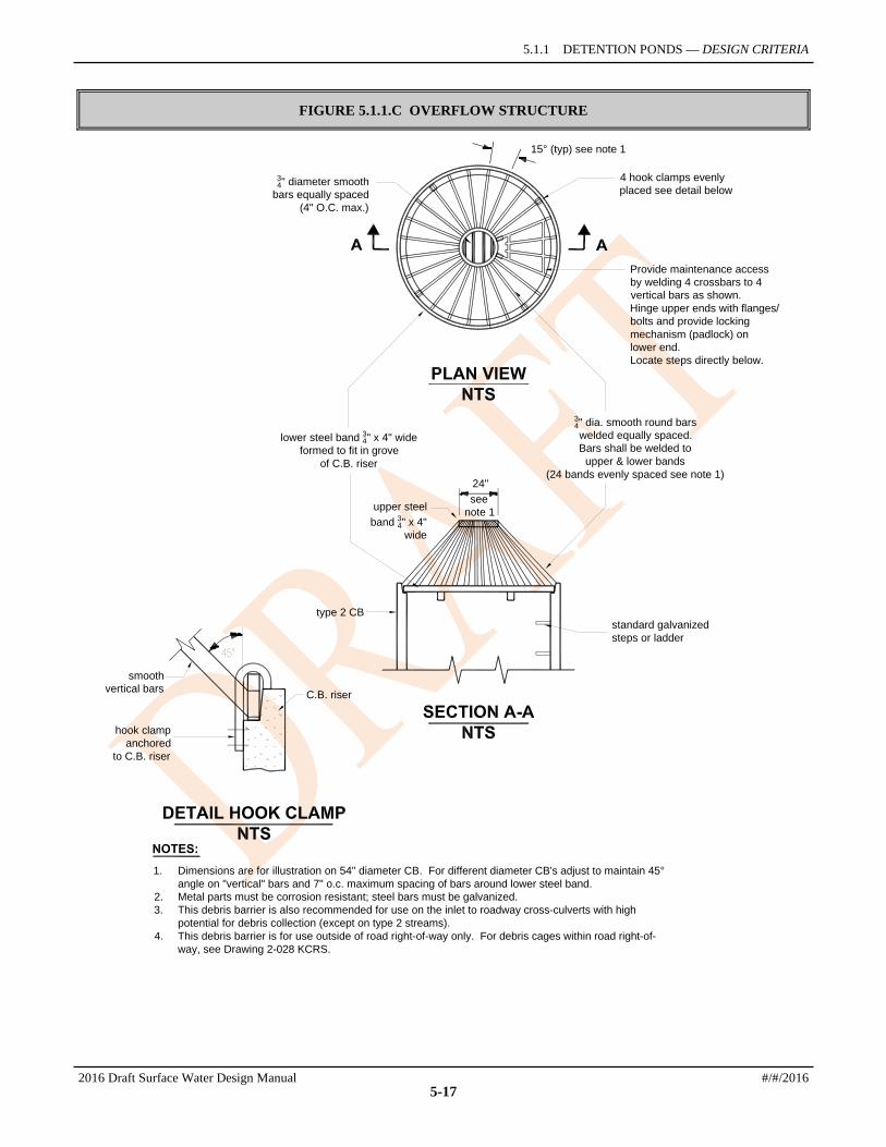
2. A secondary inlet to the control structure must be provided in ponds as additional protection against overtopping should the inlet pipe to the control structure become plugged. A grated opening ("jailhouse window") in the control structure manhole functions as a weir (see Figure 5.1.1.B, p. 5-16) when used as a secondary inlet. Note: The maximum circumferential length of this opening shall not exceed one-half the control structure circumference. The "birdcage" overflow structure as shown in Figure 5.1.1.C (p. 5-17) may also be used as a secondary inlet.
Emergency Overflow Spillway 1. In addition to the above overflow requirements, ponds must have an emergency overflow spillway
sized to pass the 100-year, 15-minute developed peak flow in the event of total control structure failure (e.g., blockage of the control structure outlet pipe) or extreme inflows. Emergency overflow spillways are intended to control the location of pond overtopping and direct overflows back into the downstream conveyance system or other acceptable discharge point.
2. Emergency overflow spillways must be provided for ponds with constructed berms over 2 feet in height, or for ponds located on grades in excess of 5%. As an option for ponds with berms less than 2 feet in height and located at grades less than 5%, emergency overflow may be provided by an emergency overflow structure, such as a Type II manhole fitted with a birdcage as shown in Figure 5.1.1.C (p. 5-17). The emergency overflow structure must be designed to pass the 100-year developed peak flow, with a minimum 6 inches of freeboard, directly to the downstream conveyance system or another acceptable discharge point. Where an emergency overflow spillway would discharge to a slope steeper than 15%, consideration should be given to providing an emergency overflow structure in addition to the spillway.
3. The emergency overflow spillway shall be armored with riprap in conformance with Table 4.2.2.A. The spillway shall be armored full width, beginning at a point midway across the berm embankment and extending downstream to where emergency overflows re-enter the conveyance system (see Figure 5.1.1.B, p. 5-16).
4. Design of emergency overflow spillways requires the analysis of a broad-crested trapezoidal weir as described in Section 5.1.1.2 (p. 5-19). Either one of the weir sections shown in Figure 5.1.1.B (p. 5-16) may be used.
Access Requirements 1. Maintenance access road(s) shall be provided to the control structure and other drainage structures
associated with the pond (e.g., inlet, emergency overflow or bypass structures). Manhole and catch basin lids must be in or at the edge of the access road and at least three feet from a property line. Rims shall be set at the access road grade.
2016 Draft Surface Water Design Manual #/#/2016
5-7

SECTION 5.1 DETENTION FACILITIES
2. An access ramp is required for removal of sediment with a trackhoe and truck. The ramp must extend to the pond bottom if the pond bottom is greater than 1500 square feet (measured without the ramp) and it may end at an elevation 4 feet above the pond bottom, if the pond bottom is less than 1,500 square feet (measured without the ramp), provided the pond side slopes are 3H:1V or flatter.
Intent: On large, deep ponds, truck access to the pond bottom via an access ramp is necessary so loading can be done in the pond bottom. On small deep ponds, the truck can remain on the ramp for loading. On small shallow ponds, a ramp to the bottom may not be required if the trackhoe can load a truck parked at the pond edge or on the internal berm of a wetpond or combined pond (trackhoes can negotiate interior pond side slopes).
3. The internal berm of a wetpond or combined detention and wetpond may be used for access if it is no more than 4 feet above the first wetpool cell, if the first wetpool cell is less than 1500 square feet (bottom area measured without the ramp), and if it is designed to support a loaded truck, considering the berm is normally submerged and saturated.
4. Access ramps shall meet the requirements for design and construction of access roads specified below.
5. All control structures shall have round, solid locking lids with 5/8-inch diameter Allen head cap screws (see the King County Road Design and Construction Standards (KCRDCS) Drawing No. 7-022 and 7-023).
6. Access shall be limited by a double-posted gate if a fence is required, or by bollards. Bollards shall be designed in accordance with the KCRDCS.
Design of Access Roads Access roads shall meet the following design criteria:
1. Maximum grade shall be 15% for asphalt paving and 12% for gravel or modular grid paving.
2. Outside turning radius shall be 40 feet, minimum.
3. Fence gates shall be located only on straight sections of road.
4. Access roads shall be 15 feet in width on curves and 12 feet on straight sections.
5. A paved apron shall be provided where access roads connect to paved public roadways. The apron shall be consistent with driveway details in the KCRDCS.
Construction of Access Roads Access roads shall be constructed with an asphalt, concrete or gravel surface, or modular grid pavement. Access roads must conform to the KCRDCS for residential minor access streets. Modular grid pavement shall meet manufacturer's specifications.
Fencing 1. A fence is required at the emergency overflow water surface elevation, or higher, where a pond
interior side slope is steeper than 3H:1V, or where the impoundment is a wall greater than 24 inches in height. The fence need only be constructed for those slopes steeper than 3H:1V.
Intent: To discourage access to portions of a pond where steep side slopes (steeper than 3H:1V) increase the potential for slipping into the pond, and to guide those who have fallen into a pond to side slopes that are flat enough (flatter than 3H:1V and unfenced) to allow for easy escape.
2. Fencing is required for ponds serving multifamily projects (or land uses) for slopes steeper than 3H:1V. For other privately owned and maintained facilities, fences are recommended, but not required, for slopes steeper than 3H:1V. Note, however, that other regulations such as the Uniform Building Code may require fencing of vertical walls. Fence material and construction specifications outlined below do not apply to private facilities.
#/#/2016 2016 Draft Surface Water Design Manual
5-8

5.1.1 DETENTION PONDS — DESIGN CRITERIA
3. Fences shall be 6 feet in height. For example designs, see WSDOT Standard Plan L-2, Type 1 or Type 3 chain link fence.
Exception: The fence may be a minimum of 4 feet in height if the depth of the impoundment (measured from the lowest elevation in the bottom of the impoundment, directly adjacent to the bottom of the fenced slope, up to the emergency overflow water surface) is 5 feet or less. For example designs, see WSDOT Standard Plan L-2, Type 4 or Type 6 chain link fence.
4. Access road gates shall be 16 feet in width consisting of two swinging sections 8 feet in width. Additional vehicular access gates may be required as needed to facilitate maintenance access.
5. Pedestrian access gates (if needed) shall be 4 feet in width.
6. For fences to be maintained by the County, fence material shall be vertical metal balusters, 9 gauge stainless steel, aluminized steel, or galvanized steel fabric. If galvanized, bonded vinyl coating is required. For steel fabric fences, the following apply:
a) Vinyl coating shall be compatible with the surrounding environment (e.g., green in open, grassy areas and black or brown in wooded areas). All posts, cross bars, and gates shall be coated the same color as the vinyl clad fence fabric.
b) Fence posts and rails shall conform to WSDOT Standard Plan L-2 for Types 1, 3, or 4 chain link fence, except that if galvanized, they must be coated with bonded vinyl.
7. For metal baluster fences, Uniform Building Code standards shall apply.
8. Wood fences are allowed in subdivisions where the fence will be maintained by homeowners associations or adjacent lot owners. Fence maintenance requirements shall be a condition of subdivision approval, and a statement detailing maintenance responsibilities and requirements must be recorded with the plat.
9. Wood fences shall have pressure treated2 posts (ground contact rated) either set in 24-inch deep concrete footings or attached to footings by steel brackets. Rails and fence boards shall be cedar.
10. Where only short stretches of the pond perimeter (< 10%) have side slopes steeper than 3H:1V, untreated cedar split rail fences (3-foot minimum height) or densely planted thorned hedges (e.g., barberry, holly, etc.) may be used in place of a standard fence.
Signage Detention ponds, infiltration ponds, wetponds, and combined ponds to be maintained by King County shall have a sign placed for maximum visibility from adjacent streets, sidewalks, and paths. The sign shall meet the design and installation requirements illustrated in Figure 5.1.1.D (p. 5-18).
Right-of-Way 1. Open detention ponds shall not be located in dedicated public road right-of-way.
2. Detention ponds to be maintained by King County shall be in a tract dedicated to King County (see Section 1.2.6). Any tract not abutting public right-of-way will require a 15-foot wide extension of the tract to an acceptable access location.
Setbacks 1. A setback of 5 feet from the toe of the exterior slope, retaining walls and rockeries to the tract or
property line is required for County-maintained ponds and recommended for privately maintained ponds.
2. The tract or property line on a detention pond cut slope shall be setback 5 feet from the emergency overflow water surface.
2 Fence posts represent a rare exception to the rule of no treated lumber. Ground contact requires pressure treatment. 2016 Draft Surface Water Design Manual #/#/2016
5-9

SECTION 5.1 DETENTION FACILITIES
3. The detention pond water surface at the pond outlet invert elevation shall be setback 100 feet from proposed or existing septic system drainfields. This setback may be reduced with written approval of the Seattle-King County Department of Public Health.
4. The detention pond design water surface shall be a minimum of 200 feet from any steep slope hazard area or landslide hazard area. Upon analysis and approval of a licensed geotechnical engineer or engineering geologist, this setback may be reduced to 50 feet. The geotechnical analysis must consider cumulative impacts from the project and surrounding areas under full built- out conditions.
5. The detention pond design water surface shall be set back a minimum distance from top of slope equal to the total vertical height of a slope area that is steeper than 15%. Upon analysis and approval of a licensed geotechnical engineer or engineering geologist, this setback may be reduced to 50 feet. The geotechnical analysis must consider cumulative impacts from the project and surrounding areas under full built- out conditions.
#/#/2016 2016 Draft Surface Water Design Manual
5-10

5.1.1 DETENTION PONDS — DESIGN CRITERIA
Seeps and Springs Intermittent seeps along cut slopes are typically fed by a shallow groundwater source (interflow) flowing along a relatively impermeable soil stratum. These flows are storm driven and should discontinue after a few weeks of dry weather. The approved continuous runoff model accounts for this shallow groundwater component, and no special provisions are needed when directing these flows through the flow control facility. However, more continuous seeps and springs, which extend through longer dry periods, are likely from a deeper groundwater source. When continuous flows are intercepted and directed through flow control facilities, adjustments to the approved facility design may be required to account for the additional base flow (unless already considered in design). If uncertain at the time of construction, the situation may be monitored while the facility is under maintenance and defect financial guarantee. Adjustments to the facility may be required prior to the release of the financial guarantee.
Planting Requirements Exposed earth on the pond bottom and interior side slopes shall be sodded or seeded with an appropriate seed mixture. All remaining areas of the tract must either be planted with grass, or be landscaped in accordance with the standards below and mulched with a 4-inch cover of hog fuel or shredded wood mulch.3
Landscaping Landscaping for aesthetic purposes is encouraged, but not required, for most stormwater tract areas containing ponds maintained by King County (see below for areas not to be landscaped). However, if provided, landscaping must adhere to the criteria that follow so as not to hinder maintenance operations. Landscaped stormwater tracts may, in some instances, be used to satisfy requirements for recreational space. In other instances, "naturalistic" stormwater facilities may be placed in open space tracts. For more information, see page 5-14.
If landscaping is proposed in the stormwater tract of a County-maintained pond, the following requirements shall apply:
1. No trees or shrubs may be planted within 10 feet of inlet or outlet pipes or manmade drainage structures such as catch basins, spillways or flow spreaders. Species with roots that seek water, such as willow or poplar, should be avoided within 50 feet of pipes or manmade structures.
2. Planting is restricted on berms that impound water either permanently or temporarily during storms. Note: This restriction does not apply to cut slopes that form pond banks, only to berms.
a) Trees or shrubs may not be planted on portions of water-impounding berms taller than four feet high. Only grasses may be planted on berms taller than four feet.
Intent: Grasses allow unobstructed visibility of berm slopes for detecting potential dam safety problems such as animal burrows, slumping, or fractures in the berm.
b) Trees planted on portions of water-impounding berms less than 4 feet high must be small, not higher than 20 feet mature height, and have a fibrous root system. Table 5.1.1.A gives some examples of trees with these characteristics.
Intent: These trees reduce the likelihood of blow-down trees, or the possibility of channeling or piping of water through the root system, which may contribute to dam failure on berms that retain water.
3. All landscape material, including grass, must be planted in good topsoil. Native underlying soils may be made suitable for planting if amended with 2 inches of well-rotted compost tilled into the top six inches of soil. Compost used should meet Ecology publication 94-38 specifications for Grade A compost quality.
3 Shredded wood mulch is made from shredded tree trimmings, usually from trees cleared onsite. It must be free of garbage and weeds and may not contain excessive resin, tannin, or other material detrimental to plant growth.
2016 Draft Surface Water Design Manual #/#/2016
5-11

SECTION 5.1 DETENTION FACILITIES
4. Soil in which trees or shrubs are planted may require additional enrichment or additional compost top-dressing. Consult a nurseryman, landscape professional, or arborist for site-specific recommendations.
5. For a naturalistic effect as well as ease of maintenance, trees or shrubs must be planted in clumps to form "landscape islands" rather than evenly spaced.
6. The landscaped islands must be planted above the 100-year water surface and must be a minimum of six feet apart, and if set back from fences or other barriers, the setback distance must also be a minimum of six feet. Where tree foliage extends low to the ground, the six feet of setback should be counted from the outer drip line of the trees (estimated at maturity).
Intent: This landscape design must allow a 6-foot wide mower to pass around and between clumps.
7. Evergreen trees and trees that produce relatively little leaf-fall such as Oregon ash, mimosa, or locust are preferred. Large-leaf deciduous trees may not be planted where branches could extend over interior pond slopes.
8. All trees shall be set back so branches do not extend over the 100-year water surface of the pond to prevent leaf-drop into the water.
9. Drought tolerant species are recommended.
10. Landscape areas within the tracts of County-maintained ponds in residential subdivision developments shall be designated "to be maintained by the homeowner's association."
TABLE 5.1.1.A SMALL TREES AND SHRUBS WITH FIBROUS ROOTS
Small Trees / High Shrubs Low Shrubs
*Red twig dogwood (Cornus stolonifera) *Snowberry (Symphoricarpus albus)
*Serviceberry (Amelanchier alnifolia) *Salmonberry (Rubus spectabilis)
Strawberry tree (Arbutus unedo) Rosa rugosa (avoid spreading varieties)
Highbush cranberry (Vaccinium opulus) Rock rose (Cistus spp.)
Blueberry (Vaccinium spp.) Ceanothus spp. (choose hardier varieties)
*Filbert (Corylus cornuta, others) New Zealand flax (Phormium penax)
Fruit trees on dwarf rootstock
Rhododendron (native and ornamental varieties)
Ornamental grasses (e.g., Miscanthis, Pennisetum)
* Native species
Guidelines for Naturalistic Planting Stormwater facilities may sometimes be located within open space tracts if "natural appearing" (see page 5-14 for details). Two generic kinds of naturalistic planting are outlined below, but other options are also possible. A booklet discussing stormwater ponds and landscaping possibilities is available at the Water and Land Resources Division; when completed, it should be consulted for additional ideas. Native vegetation is preferred in naturalistic plantings.
Note: These landscaping criteria must be followed unless a landscape professional judges that long-term quality of the open space would be improved by deviating from the criteria, AND that if the facility is maintained by the County, maintenance would not be made more difficult by the deviations.
#/#/2016 2016 Draft Surface Water Design Manual
5-12

5.1.1 DETENTION PONDS — DESIGN CRITERIA
Open Woodland In addition to the general landscaping criteria above, the following requirements must be met:
1. Landscaped islands (when mature) should cover a minimum of 30% or more of the tract, exclusive of the pond area.
2. Tree clumps should be underplanted with shade-tolerant shrubs and groundcover plants. The goal is to provide a dense understory that need not be weeded or mowed.
3. Landscaped islands should be placed at several elevations rather than "ring" the pond, and the size of clumps should vary from small to large to create variety.
4. Not all islands need have trees. Shrub or groundcover clumps are acceptable, but lack of shade should be considered in selecting vegetation.
Note: Landscaped islands are best combined with the use of hog fuel or shredded wood mulch for erosion control (only for slopes above the flow control water surface). It is often difficult to sustain a low-maintenance understory if the area was previously hydroseeded.
Northwest Savannah or Meadow In addition to the general landscape criteria above, the following requirements must be met:
1. Landscape islands (when mature) should cover 10% or more of the tract, exclusive of the pond area.
2. Planting groundcovers and understory shrubs is encouraged to eliminate the need for mowing under the trees when they are young.
3. Landscape islands should be placed at several elevations rather than "ring" the pond.
4. The remaining tract area should be planted with an appropriate grass seed mix, which may include northwest meadow or wildflower species. Native or dwarf grass mixes are preferred. Table 5.1.1.B below gives one acceptable dwarf grass mix. Grass seed should be applied at 2.5 to 3 pounds per 1000 square feet. Note: Amended soil or good topsoil is required for all plantings.
5. Creation of areas of emergent vegetation in shallow areas of the pond is recommended. Native wetland plants, such as sedges (Carex sp.), bulrush (Scirpus sp.), water plantain (Alisma sp.), and burreed (Sparganium sp.) are recommended. If the pond does not hold standing water, a clump of wet-tolerant, non-invasive shrubs, such as salmonberry or snowberry, is recommended below the detention design water surface.
Note: This landscape style is best combined with the use of grass or sod for site stabilization and erosion control.
TABLE 5.1.1.B STORMWATER TRACT "LOW-GROW" SEED MIX
Seed Name Percentage of Mix
Dwarf tall fescue 40%
Dwarf perennial rye "Barclay" * 30%
Red fescue 25%
Colonial bentgrass 5%
* If wildflowers are used and sowing is done before Labor Day, the amount of dwarf perennial rye may be reduced proportionately to the amount of wildflower seed used.
2016 Draft Surface Water Design Manual #/#/2016
5-13

SECTION 5.1 DETENTION FACILITIES
Detention Ponds in Recreational Tracts Projects required to provide onsite recreational space per KCC 21A.14.180 may combine the detention pond tract with the recreation space tract to receive a 50% reduction in required onsite recreational space. To receive the 50% credit, the following criteria must be met as required by KCC 21A.14.180.D:
1. The proposed stormwater tract must be dedicated or reserved as a part of a recreational space tract.
2. The stormwater pond must meet all standards for typical ponds unless modified by the following additional requirements:
a) Side slopes shall not exceed 33 percent unless they are existing, natural, and covered with vegetation.
b) A bypass system or an emergency overflow pathway shall be designed to handle flow exceeding the facility design and located so that it does not pass through active recreation areas or present a safety hazard.
c) The area surrounding the stormwater pond shall be landscaped in a manner to enhance passive recreational opportunities such as trails and aesthetic viewing.
d) The stormwater pond shall be designed so that it does not require fencing per the fencing requirements on page 5-8.
e) Split rail fencing (3 ft. minimum height) is required around the pond at the emergency overflow elevation of the pond or higher. Wire mesh backing of the fence is encouraged, but not required. Intent: To preserve the functional integrity of the pond while allowing view of facility.
3. Where a tract is jointly used for recreational space and King County maintained drainage facilities, the County is only responsible for maintenance of the drainage facilities, and an access easement shall be provided for that purpose.
Detention Ponds in Open Space Open space areas reserved through the four-to-one program may be used to site "natural appearing" stormwater facilities if they are found to be compatible with the open space value and functions, and if they are located on a "small portion of the open space" (Amended policy I-204, King County Comprehensive Plan). Conscientious application of the "Guidelines for Naturalistic Plantings" (p. 5-12) typically will produce natural-appearing stormwater facilities. A site-specific assessment is needed, however, to determine whether the stormwater tract would be compatible with the open space value and functions.
#/#/2016 2016 Draft Surface Water Design Manual
5-14

5.1.1 DETENTION PONDS — DESIGN CRITERIA
FIGURE 5.1.1.A TYPICAL DETENTION POND
alternate emergency outflowstructure for ponds not requiredto provide a spillway(Figure 5.3.1.C)
access ramp into pondsee Section 5.3.1.1
compactedembankment
6" sedimentstorage
pond designwater surface
tract lines as required
see Figure 5.3.1.Bfor section cutdiagrams
emergency overflow
spillway rock lining
per Table 4.4.1.A
pond inlet pipe
controlstructure
15% max.slope
flow
This detail is a schematic representation only. Actual configurationwill vary depending on specific site constraints and applicabledesign criteria.
flow
flow
5' min.
12'/1
5' m
aint
enan
ce ro
ad
levelbottom
flow
2016 Draft Surface Water Design Manual #/#/2016
5-15

SECTION 5.1 DETENTION FACILITIES
FIGURE 5.1.1.B TYPICAL DETENTION POND SECTIONS
overflow WS
design WS
rock lining perTable 4.4.1.A
compactedembankment
emergency overflow WS
(as required)
2" asphalt(for spillway on access roads)
design WSoverflow WS
emergency overflow water surface(see Figure 5.3.1.E)
1' rock lining
101
101
31
31
Emergency Overflow SpillwayNTS
SECTION B-B
SECTION B-B has 2 options
SECTION a-aNTS
SECTION C-CNTS
SECTION A-ANTS
Frame/grate for secondary inlet.Provide vertical bars in frame @4" O.C. (other flow systemsacceptable if approved by DDES)See also the separate overflowstructure shown in Figure 5.3.1.C
circumference length of opening sized for 100 yr flow
overflow WSpond design
W.S.
6" sedimentstorage
overflow WS
pond design WS
emergency overflow WScontrol structure
top width of berm6' min.12'/15' min. foraccess road
existing ground profile
maximumelevation10-yr W.S.key, if required
berm embarkment
debris barriersee Figure 4.2.1.D
12 min.
6" min. freeboard
#/#/2016 2016 Draft Surface Water Design Manual
5-16
5.1.1 DETENTION PONDS — DESIGN CRITERIA
FIGURE 5.1.1.C OVERFLOW STRUCTURE
upper steelband 34" x 4"
wide
lower steel band 34" x 4" wideformed to fit in grove
of C.B. riser
34" dia. smooth round barswelded equally spaced.Bars shall be welded to
upper & lower bands(24 bands evenly spaced see note 1)
standard galvanizedsteps or ladder
hook clampanchored
to C.B. riser
type 2 CB
C.B. riser
smoothvertical bars
24"see
note 1
1. Dimensions are for illustration on 54" diameter CB. For different diameter CB's adjust to maintain 45°angle on "vertical" bars and 7" o.c. maximum spacing of bars around lower steel band.
2. Metal parts must be corrosion resistant; steel bars must be galvanized.3. This debris barrier is also recommended for use on the inlet to roadway cross-culverts with high
potential for debris collection (except on type 2 streams).4. This debris barrier is for use outside of road right-of-way only. For debris cages within road right-of-
way, see Drawing 2-028 KCRS.
Provide maintenance accessby welding 4 crossbars to 4vertical bars as shown.Hinge upper ends with flanges/bolts and provide lockingmechanism (padlock) on lower end.Locate steps directly below.
34" diameter smooth
bars equally spaced(4" O.C. max.)
4 hook clamps evenlyplaced see detail below
15° (typ) see note 1
2016 Draft Surface Water Design Manual #/#/2016
5-17

SECTION 5.1 DETENTION FACILITIES
FIGURE 5.1.1.D PERMANENT SURFACE WATER CONTROL POND SIGN
SPECIFICATIONS:
Size: 48 inches by 24 inches
Material: 0.125-gauge aluminum
Face: Non-reflective vinyl or 3 coats outdoor enamel (sprayed).
Lettering: Silk screen enamel where possible, or vinyl letters.
Colors: Beige background, teal letters.
Type face: Helvetica condensed. Title: 3 inch; Sub-Title: 11/2 -inch; Text: 1 inch; Outer border: 1/8 inch border distance from edge: 1/
4-inch; all text 13/4 -inch from border.
Posts: Pressure treated, beveled tops, 11/2 -inch higher than sign.
Installation: Secure to chain link fence if available. Otherwise install on two 4"x4" posts, pressure treated, mounted atop a gravel bed, installed in 30-inch concrete filled post holes (8-inch minimum diameter), with the top of sign no higher than 42 inches from ground surface.
Placement: Face sign in direction of primary visual or physical access. Do not block any access road. Do not place within 6 feet of structural facilities (e.g. manholes, spillways, pipe inlets).
Note: If the facility has a liner to restrict infiltration of stormwater, the following note must be added to the face of the sign: "This facility is lined to protect groundwater quality." In addition, specific information about the liner must be added to the back of the sign as specified in Section 6.2.4.
StormwaterPond
King CountyDepartement ofNatural Resourcesand Parks
This pond is in our care.
Runoff is held here after storms. It is releasedslowly or stored until the next storm when it isreplaced by incoming flows. This helps preventdownstream flooding and erosion and helpsclean the water. For more information or to reportlittering, vandalism or other problems, callDepartment of Natural Resources FacilitiesMaintenance at (206) 296-8100.
Pond Name and Number
48"
1 12"
24"
3' - 6" (typ)
#/#/2016 2016 Draft Surface Water Design Manual
5-18

5.1.1 DETENTION PONDS — DESIGN CRITERIA
5.1.1.2 METHODS OF ANALYSIS
Detention Volume and Outflow The volume and outflow design for detention ponds shall be in accordance with the performance requirements in Chapter 1 and the hydrologic analysis and design methods in Chapter 3. Restrictor orifice structure design shall comply with Section 5.1.4 (p. 5-28). Note: The design water surface elevation is the highest elevation that occurs in order to meet the required outflow performance for the pond.
Detention Ponds in Infiltrative Soils Detention ponds may occasionally be sited on till soils that otherwise meet the basic criteria of "sufficient permeable soil" for a properly functioning infiltration system (see Section 5.2.1, p. 5-47). These detention ponds have a surface discharge and may also utilize infiltration as a second pond outflow. Detention ponds sized with infiltration as a second outflow must meet all the requirements of Section 5.2 for infiltration ponds, including a soils report, performance testing, groundwater protection, presettling, and construction techniques.
Emergency Overflow Spillway Capacity The emergency overflow spillway weir section shall be designed to pass the 100-year runoff event for developed conditions assuming a broad-crested weir. The broad-crested weir equation for the spillway section in Figure 5.1.1.E, for example, would be:
Q100 = C (2g)1/2
[2/3 LH3/2
+ 8/15 (Tan θ) H5/2
] (5-1)
where Q100 = peak flow for the 100-year runoff event (cfs) C = discharge coefficient (0.6) g = gravity (32.2 ft/sec2) L = length of weir (ft) H = height of water over weir (ft) θ = angle of side slopes
Assuming C = 0.6 and Tan θ = 3 (for 3H:1V slopes), the equation becomes:
Q100 = 3.21 (LH3/2
+ 2.4 H5/2
) (5-2)
To find width L for the weir section, the equation is rearranged to use the computed Q100 and trial values of H (0.2 feet minimum):
L = [Q100 / (3.21 H3/2
)] - 2.4 H or 6 feet minimum (5-3)
FIGURE 5.1.1.E WEIR SECTION FOR EMERGENCY OVERFLOW SPILLWAY
emergency overflowwater surface
overflowwater
surface.5' min.
.2' min.
rock liningper Table 4.4.1.A
.7' min. 0 31
31
L
H
2016 Draft Surface Water Design Manual #/#/2016
5-19

SECTION 5.1 DETENTION FACILITIES
5.1.2 DETENTION TANKS Detention tanks are underground storage facilities typically constructed with large diameter corrugated metal pipe. Standard detention tank details are shown in Figure 5.1.2.A (p. 5-22) and Figure 5.1.2.B (p. 5-23). Control structure details are shown in Section 5.1.4 beginning on page 5-28.
5.1.2.1 DESIGN CRITERIA
General 1. Tanks shall be designed as flow-through systems with manholes in line (see Figure 5.1.2.A, p. 5-22)
to promote sediment removal and facilitate maintenance.
Exception: Tanks may be designed as back-up systems if preceded by water quality facilities since little sediment should reach the inlet/control structure and low head losses can be expected because of the proximity of the inlet/control structure to the tank.
2. The detention tank bottom shall be located a minimum of 0.5 feet below the inlet and outlet to provide dead storage for sediment.
3. The minimum pipe diameter allowed for a detention tank is 36 inches.
4. Tanks larger than 36 inches may be connected to each adjoining structure with a short section (2-foot maximum length) of 36-inch minimum diameter pipe.
5. Outflow control structures shall be as detailed in Section 5.1.4 (p. 5-28). Note: Control and access manholes shall have additional ladder rungs to allow ready access to all tank access pipes when the catch basin sump is filled with water (see Figure 5.1.4.A, plan view, p. 5-29).
Materials Pipe material, joints, and protective treatment for tanks shall be in accordance with Sections 7.04 and 9.05 of the WSDOT/APWA Standard Specification as modified by the King County Road Design and Construction Standards (KCRDCS) and AASHTO designations. Such materials include the following:
• Lined corrugated polyethylene pipe (LCPE)
• Aluminized Type 2 corrugated steel pipe and pipe arch (meets AASHTO designations M274 and M36)
• Corrugated or spiral rib aluminum pipe and pipe arch
• Reinforced concrete pipe
• Narrow concrete vaults (see Section 5.1.3, p. 5-24).
• Corrugated steel pipe and pipe arch, Aluminized or Galvanized4 with treatments 1, 2 or 5
• Spiral rib steel pipe, Aluminized or Galvanized with treatments 1, 2 or 5
• Structural plate pipe and pipe arch, Aluminized or Galvanized with treatments 1, 2 or 5
Structural Stability Tanks shall meet structural requirements for overburden support and traffic loading if appropriate. H-20 live loads must be accommodated for tanks lying under parking areas and access roads. The KCRDCS may have different live load requirements for structures located under roadways. Metal tank end plates
4 Galvanized metals leach zinc into the environment, especially in standing water situations. High zinc concentrations, sometimes in the range that can be toxic to aquatic life, have been observed in the region. Therefore, use of galvanized materials should be avoided. Where other metals, such as aluminum or stainless steel, or plastics are available, they shall be used. If these materials are not available, asphalt coated galvanized materials may then be used.
#/#/2016 2016 Draft Surface Water Design Manual
5-20

5.1.2 DETENTION TANKS
must be designed for structural stability at maximum hydrostatic loading conditions. Flat end plates generally require thicker gage material than the pipe and/or require reinforcing ribs.
Tanks shall be placed on stable, well consolidated native material with a suitable bedding. Backfill shall be placed and compacted in accordance with the pipe specifications in Chapter 4. Tanks made of LCPE require inspection for deformation prior to installation as well as continuous inspection of backfilling to one foot above the top of the tank. Tanks shall not be allowed in fill slopes, unless analyzed in a geotechnical report for stability and constructability.
Buoyancy In moderately pervious soils where seasonal groundwater may induce flotation, buoyancy tendencies must be balanced either by ballasting with backfill or concrete backfill, providing concrete anchors, increasing the total weight, or providing subsurface drains to permanently lower the groundwater table. Calculations must be submitted that demonstrate stability.
Access Requirements 1. The maximum depth from finished grade to tank invert shall be 20 feet.
2. Access openings shall be positioned a maximum of 50 feet from any location within the tank.
3. All tank access openings shall have round, solid locking lids with 5/8-inch diameter Allen head cap screws (see KCRDCS Drawing No. 7-022 and 7-023).
4. Thirty-six-inch minimum diameter CMP riser-type manholes (Figure 5.1.2.B, p. 5-23) of the same gage as the tank material may be used for access along the length of the tank and at the upstream terminus of the tank if a backup system. The top slab is separated (1-inch minimum gap) from the top of the riser to allow for deflections from vehicle loadings without damaging the riser tank.
5. All tank access openings must be readily accessible by maintenance vehicles.
Access Roads Access roads are required to all detention tank control structures and risers. The access roads shall be designed and constructed as specified for detention ponds in Section 5.1.1 (p. 5-8).
Right-of-Way Detention tanks to be maintained by King County but not located in King County right-of-way shall be in a tract dedicated to King County. Any tract not abutting public right-of-way will require a 15-foot wide extension of the tract to accommodate an access road to the facility.
Setbacks Setbacks (easement/tract width) and building setback lines (BSBLs) for tanks shall be the same as for pipes (see Section 4.1).
5.1.2.2 METHODS OF ANALYSIS
Detention Volume and Outflow The volume and outflow design for detention tanks shall be in accordance with the performance requirements in Chapter 1 and the hydrologic analysis and design methods in Chapter 3. Restrictor and orifice design shall be according to Section 5.1.4 (p. 5-28).
2016 Draft Surface Water Design Manual #/#/2016
5-21

SECTION 5.1 DETENTION FACILITIES
FIGURE 5.1.2.A TYPICAL DETENTION TANK
2" min. diameter air ventpipe welded to tank(required if no accessriser on tank)
"Flow-through" system shown solid.Designs for "flow backup" system and
parallel tanks shown dashed
"Flow-through" system shown solid.
All metal parts corrosion resistant.Steel parts galvanized and asphaltcoated (Treatment 1 or better)
control structure(FROP-T shown)
min. 54" dia.Type 2 CB
see Section 5.3.4
NOTE:
SECTION A-ANTS
PLAN VIEWNTS
36" min.diameter (typ)
0.5' sediment storage
detention tanksize as required
access risers100' max
50' max
2' max
2' min2' min 2' max
access risers(max spacing shown below)
2' min
access risersSee Figure 5.3.2.B
controlstructure
inlet pipe(backup systems,
where allowed)
type 2 CB requiredfor flow throughsystem only
inlet pipe(flow through)
min. diametersame as inlet pipe
optional parallel tank
36"
36"
#/#/2016 2016 Draft Surface Water Design Manual
5-22

5.1.2 DETENTION TANKS
FIGURE 5.1.2.B DETENTION TANK ACCESS DETAIL
standard type 2-60" diam.CB concrete top slab
36" CMP riser
frame locking lid(marked "DRAIN")mounted over 24" diam.eccentric opening
6"
detention tank
standard lockingM.H. frame & cover see K.C.R.S. dwg. no. 2-022
riser, 36" diam. min.,same material & gage astank welded or fused to tank
maintain 1" gap betweenbottom of slab & top ofriser - provide pliablegasket to exclude dirt
compacted pipe bedding
M.H. steps 12" O.C.
weld or boltstandard M.H. steps
24"max
36"
1. Use adjusting blocks as required to bring frame to guide.2. All materials to be aluminum or galvanized and asphalt coated (Treament 1 or better).3. Must be located for access by maintenance vehicles.4. May substitute WSDOT special Type IV manhole (RCP only).
PLANNTS
SECTIONNTS
2016 Draft Surface Water Design Manual #/#/2016
5-23

SECTION 5.1 DETENTION FACILITIES
5.1.3 DETENTION VAULTS Detention vaults are box-shaped underground storage facilities typically constructed with reinforced concrete. A standard detention vault detail is shown in Figure 5.1.3.A (p. 5-27). Control structure details are shown in Section 5.1.4 beginning on page 5-28.
5.1.3.1 DESIGN CRITERIA
General 1. Detention vaults shall be designed as flow-through systems with bottoms level (longitudinally) or
sloped toward the inlet to facilitate sediment removal. Distance between the inlet and outlet shall be maximized (as feasible).
2. The detention vault bottom shall slope at least 5% from each side towards the center, forming a broad "v" to facilitate sediment removal. Note: More than one "v" may be used to minimize vault depth.
Exception: The vault bottom may be flat if removable panels are provided over the entire vault. Removable panels shall be at grade, have stainless steel lifting eyes, and weigh no more than 5 tons per panel.
3. The invert elevation of the outlet shall be elevated above the bottom of the vault to provide an average 6 inches of sediment storage over the entire bottom. The outlet must also be elevated a minimum of 2 feet above the orifice to retain oil within the vault.
4. The outflow system and restrictor device shall be designed according to the applicable requirements specified for control structures in Section 5.1.4 (p. 5-28).
Materials Minimum 3,000 psi structural reinforced concrete must be used for all detention vaults. All construction joints must be provided with water stops.
Structural Stability All vaults shall meet structural requirements for overburden support and H-20 traffic loading. Vaults located under roadways must meet the live load requirements of the King County Road Design and Construction Standards (KCRDCS). Cast-in-place wall sections shall be designed as retaining walls. Structural designs for vaults must be stamped by a licensed structural engineer unless otherwise approved by DPER. Vaults shall be placed on stable, well-consolidated native material with suitable bedding. Vaults shall not be allowed in fill slopes, unless analyzed in a geotechnical report for stability and constructability.
Access Requirements 1. Access consisting of a frame, grate and locking cover shall be provided over the inlet pipe and outlet
structure and located in a manner to allow visual inspection. Access openings over control structures shall meet a minimum 2 ft. offset to any portion of the FROP-T as shown in figure 5.3.4.A. Access openings shall be positioned a maximum of 50 feet from any location within the vault; additional access points may be required on large vaults. If more than one "v" is provided in the vault floor, access to each "v" must be provided.
2. For vaults with greater than 1250 square feet of floor area, a 5' by 10' removable, locking panel shall be provided. Alternatively, a separate access vault may be provided as shown in Figure 5.1.3.A (p. 5-27).
3. For vaults under roadways, the removable panel must be located outside the travel lanes. Alternatively, multiple standard locking manhole covers (see KCRDCS Drawing No. 7-022 and 7-
#/#/2016 2016 Draft Surface Water Design Manual
5-24

5.1.3 DETENTION VAULTS
023) may be provided. Spacing of manhole covers shall be 12 feet, measured on center, to facilitate removal of sediment. Ladders and hand-holds need only be provided at the outlet pipe and inlet pipe, and as needed to meet OSHA confined space requirements. Vaults providing manhole access at 12-foot spacing need not provide corner ventilation pipes as specified in Item 9 below.
4. All access openings, except those covered by removable panels, shall have round, solid locking covers (see KCRDCS Drawing Nos. 7-022 and 7-023), or 3-foot square, locking diamond plate covers. For raised openings where the depth from the iron cover to the top of the vault exceeds 24 inches, an access structure equivalent to a Type 2 catch basin or Type 1 manhole shall be used (see KCRDCS Drawing Nos. 7-005 and 7-007). The opening in the vault lid need not exceed 24 inches in diameter.
5. Vaults with widths 10 feet or less must have removable lids.
6. The maximum depth from finished grade to the vault invert shall be 20 feet.
7. Internal structural walls of large vaults shall be provided with openings sufficient for maintenance access between cells. The openings shall be sized and situated to allow access to the maintenance "v" in the vault floor.
8. The minimum internal height shall be 7 feet from the highest point of the vault floor (not sump), and the minimum width shall be 4 feet.
Exceptions:
• Concrete vaults may be a minimum 3 feet in height and width if used as tanks with access manholes at each end, and if the width is no larger than the height.
• The minimum internal height requirement may be waived for any areas covered by removable panels.
9. Ventilation pipes (minimum 12-inch diameter or equivalent) shall be provided in all four corners of vaults to allow for artificial ventilation prior to entry of maintenance personnel into the vault. These openings shall be capped or otherwise covered, but designed so that maintenance personnel can remove (and replace) for ventilation purposes as described.
Access Roads Access roads are required to the access panel (if applicable), the control structure, and at least one access point per cell, and they shall be designed and constructed as specified for detention ponds in Section 5.1.1 (p. 5-8).
Right-of-Way Detention vaults to be maintained by King County but not located in King County right-of-way shall be in a tract dedicated to King County. Any tract not abutting public right-of-way will require a 15-foot wide extension of the tract to accommodate an access road to the vault.
Setbacks Setbacks to tract/easement lines for vaults shall be 5 feet; adjacent building setback lines shall be 10 feet. For privately owned and maintained vaults, building foundations may serve as one or more of the vault walls.
2016 Draft Surface Water Design Manual #/#/2016
5-25

SECTION 5.1 DETENTION FACILITIES 5.1.3.2 METHODS OF ANALYSIS
Detention Volume and Outflow The volume and outflow design for detention vaults shall be in accordance with the performance requirements in Chapter 1 and the hydrologic analysis and routing/design methods in Chapter 3. Restrictor and orifice design shall be according to Section 5.1.4 (p. 5-28).
#/#/2016 2016 Draft Surface Water Design Manual
5-26

5.1.3 DETENTION VAULTS
FIGURE 5.1.3.A TYPICAL DETENTION VAULT
2016 Draft Surface Water Design Manual #/#/2016
5-27

SECTION 5.1 DETENTION FACILITIES
5.1.4 CONTROL STRUCTURES Control structures are catch basins or manholes with a restrictor device for controlling outflow from a facility to meet the desired performance. The restrictor device is typically a tee section with an orifice plate welded to the bottom (called a "FROP-T"). To meet performance requirements, one or more elbow sections with orifice plates may need to be mounted on the side of the tee section. The restrictor device may also be a weir section sized to meet performance requirements.
Standard control structure details are shown in Figure 5.1.4.A (p. 5-29) through Figure 5.1.4.C (p. 5-31).
5.1.4.1 DESIGN CRITERIA
Multiple Orifice Restrictor In most cases, control structures need only two orifices: one at the bottom and one near the top of the riser, although additional orifices may best utilize detention storage volume. Several orifices may be located at the same elevation if necessary to meet performance requirements.
1. Minimum orifice diameter is 0.25 inches. Note: In some instances, a 0.25-inch bottom orifice may be too large to meet target release rates, even with minimal head. In these cases, the live storage depth need not be reduced to less than 3 feet to meet performance.
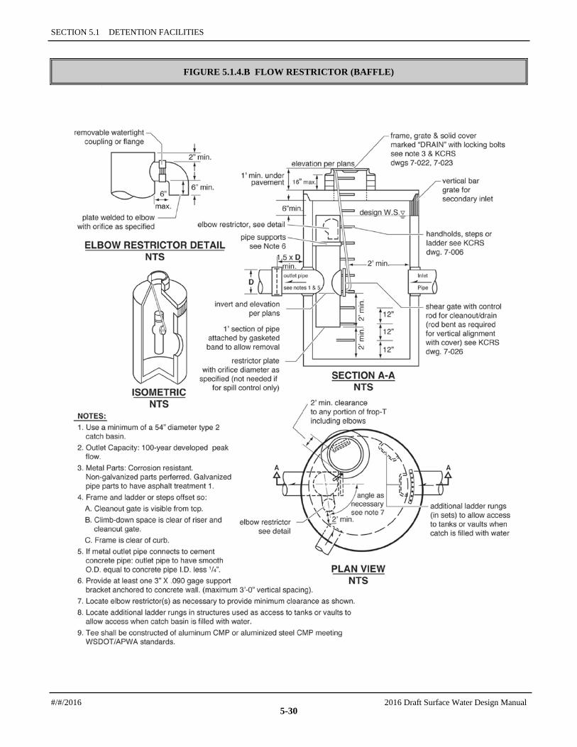
2. Orifices shall be constructed on a tee section as shown in Figure 5.1.4.A (p. 5-29) or on a baffle as shown in Figure 5.1.4.B (p. 5-30).
3. In some cases, performance requirements may require the top orifice/elbow to be located too high on the riser to be physically constructed (e.g., a 13-inch diameter orifice positioned 0.5 feet from the top of the riser). In these cases, a notch weir in the riser pipe may be used to meet performance requirements (see Figure 5.1.4.E, p. 5-34).
4. Consideration shall be given to the backwater effect of water surface elevations in the downstream conveyance system. High tailwater elevations may affect performance of the restrictor system and reduce live storage volumes.
Riser and Weir Restrictor 1. Properly designed weirs may be used as flow restrictors (see Figure 5.1.4.C and Figure 5.1.4.E
through Figure 5.1.4.F). However, they must be designed to provide for primary overflow of the developed 100-year peak flow discharging to the detention facility.
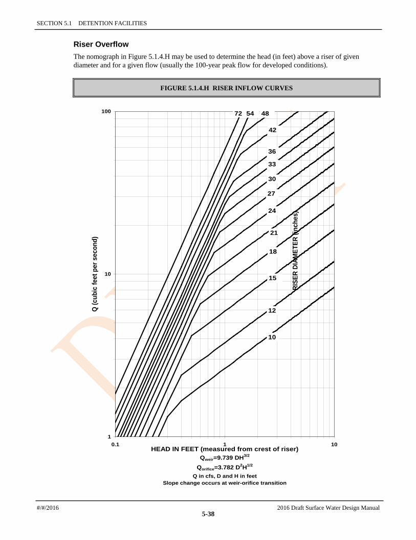
2. The combined orifice and riser (or weir) overflow may be used to meet performance requirements; however, the design must still provide for primary overflow of the developed 100-year peak flow assuming all orifices are plugged. Figure 5.1.4.H (p. 5-38) may be used to calculate the head in feet above a riser of given diameter and flow.
Access Requirements 1. An access road to the control structure is required for inspection and maintenance, and shall be
designed and constructed as specified for detention ponds in Section 5.1.1 (p. 5-8).
2. Manhole and catch basin lids for control structures shall be locking, and rim elevations shall match proposed finish grade.
3. The restrictor tee shall be located immediately adjacent to the 2-foot clear zone at a maintenance access ladder. Intent: To provide tee visibility from the surface at the access opening, especially where a solid vault lid or solid manhole lid design may block view; to provide maintenance access along the full height of the tee.
#/#/2016 2016 Draft Surface Water Design Manual
5-28

5.1.4 CONTROL STRUCTURES — DESIGN CRITERIA
FIGURE 5.1.4.A FLOW RESTRICTOR (TEE)
2016 Draft Surface Water Design Manual #/#/2016
5-29
SECTION 5.1 DETENTION FACILITIES
FIGURE 5.1.4.B FLOW RESTRICTOR (BAFFLE) F
#/#/2016 2016 Draft Surface Water Design Manual
5-30
5.1.4 CONTROL STRUCTURES — DESIGN CRITERIA
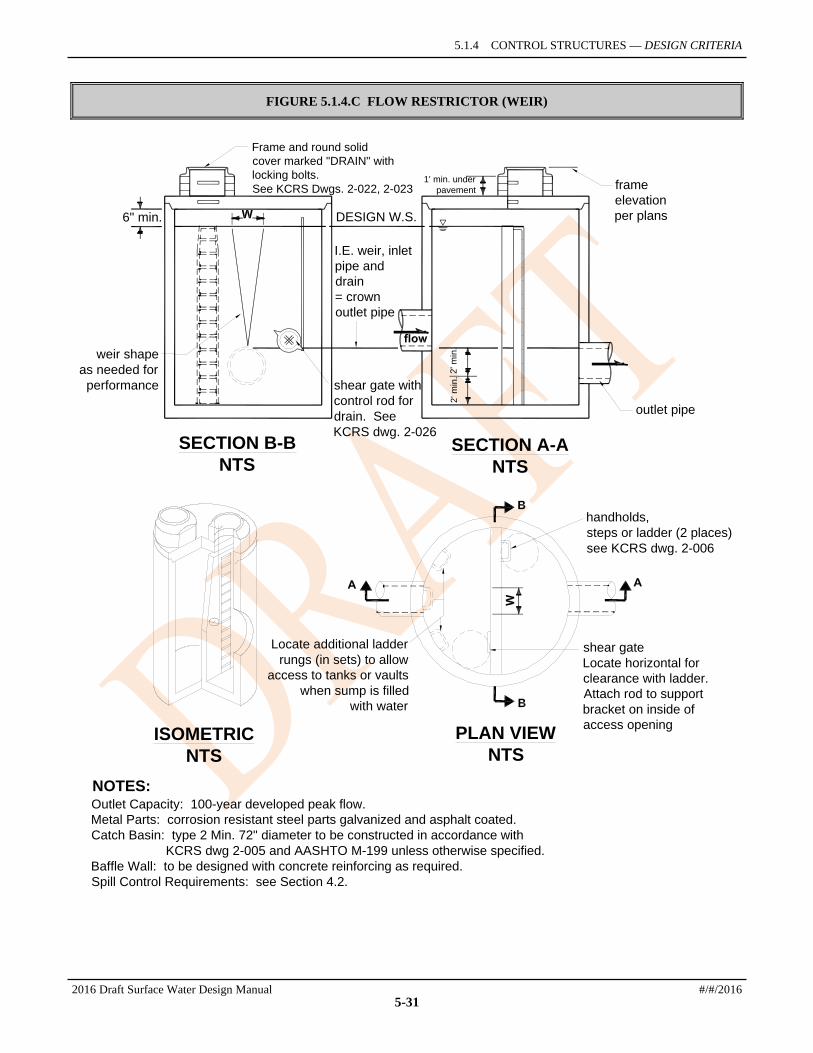
FIGURE 5.1.4.C FLOW RESTRICTOR (WEIR)
Locate additional ladderrungs (in sets) to allow
access to tanks or vaultswhen sump is filled
with water
shear gateLocate horizontal forclearance with ladder.Attach rod to supportbracket on inside ofaccess opening
handholds,steps or ladder (2 places)see KCRS dwg. 2-006
frameelevationper plans
outlet pipe
shear gate withcontrol rod fordrain. SeeKCRS dwg. 2-026
I.E. weir, inletpipe anddrain= crownoutlet pipe
DESIGN W.S.
1' min. underpavement
weir shapeas needed for
performance
Frame and round solidcover marked "DRAIN" withlocking bolts.See KCRS Dwgs. 2-022, 2-023
2' m
in.
2' m
in.
6" min.
Outlet Capacity: 100-year developed peak flow.Metal Parts: corrosion resistant steel parts galvanized and asphalt coated.Catch Basin: type 2 Min. 72" diameter to be constructed in accordance with
KCRS dwg 2-005 and AASHTO M-199 unless otherwise specified.Baffle Wall: to be designed with concrete reinforcing as required.Spill Control Requirements: see Section 4.2.
NOTES:
SECTION B-BNTS
SECTION A-ANTS
ISOMETRICNTS
PLAN VIEWNTS
2016 Draft Surface Water Design Manual #/#/2016
5-31

SECTION 5.1 DETENTION FACILITIES
5.1.4.2 METHODS OF ANALYSIS This section presents the methods and equations for design of control structure restrictor devices. Included are details for the design of orifices, rectangular sharp-crested weirs, v-notch weirs, sutro weirs, and overflow risers.
Orifices Flow through orifice plates in the standard tee section or turn-down elbow may be approximated by the general equation:
Q = CA gh2 (5-4)
where Q = flow (cfs) C = coefficient of discharge (0.62 for plate orifice) A = area of orifice (sf) h = hydraulic head (ft) g = gravity (32.2 ft/sec
2)
Figure 5.1.4.D illustrates a simplified application of the orifice equation, assuming a water surface at the top of the riser and that the 2-year water surface represents the head in the outlet pipe.
FIGURE 5.1.4.D SIMPLE ORIFICE
h = distance from hydraulic grade line at the 2-year flow of the outflow pipe to the overflow elevation.
= C
Q = CA 2gh
2g h h (A + A )t2gh
b b
b + CA
t
b
t
orifice (b)
orifice (t)
The diameter of the orifice is calculated from the flow. The orifice equation is often useful when expressed as the orifice diameter in inches:
d = h
Q88.36 (5-5)
where d = orifice diameter (inches) Q = flow (cfs)
#/#/2016 2016 Draft Surface Water Design Manual
5-32

5.1.4 CONTROL STRUCTURES — METHODS OF ANALYSIS
h = hydraulic head (ft)
2016 Draft Surface Water Design Manual #/#/2016
5-33

SECTION 5.1 DETENTION FACILITIES
Rectangular, Sharp-Crested Weir The rectangular, sharp-crested weir design shown in Figure 5.1.4.E may be analyzed using standard weir equations for the fully contracted condition.
FIGURE 5.1.4.E RECTANGULAR, SHARP-CRESTED WEIR
Q = C (L - 0.2H)H3/2
(5-6)
where Q = flow (cfs) C = 3.27 + 0.40 H/P (ft) H,P are as shown above L = length (ft) of the portion of the riser circumference as necessary not to exceed 50% of
the circumference D = inside riser diameter (ft) Note that this equation accounts for side contractions by subtracting 0.1H from L for each side of the notch weir.
SECTIONNTS
PLAN VIEWNTS
riser
#/#/2016 2016 Draft Surface Water Design Manual
5-34

5.1.4 CONTROL STRUCTURES — METHODS OF ANALYSIS
V-Notch, Sharp-Crested Weir V-notch weirs, as shown in Figure 5.1.4.F, may be analyzed using standard equations for the fully contracted condition.
FIGURE 5.1.4.F V-NOTCH, SHARP-CRESTED WEIR
Y (in feet)
Where values of C may be taken from the following chart:
Q = C (Tan 0 / 2)Y , in cfsd52
SECTION A-ANTS
d
dC
2016 Draft Surface Water Design Manual #/#/2016
5-35

SECTION 5.1 DETENTION FACILITIES
Proportional or Sutro Weir Sutro weirs are designed so that the discharge is proportional to the total head. This design may be useful in some cases to meet performance requirements.
The sutro weir consists of a rectangular section joined to a curved portion that provides proportionality for all heads above the line A-B (see Figure 5.1.4.G). The weir may be symmetrical or non-symmetrical.
FIGURE 5.1.4.G SUTRO WEIR
For this type of weir, the curved portion is defined by the following equation (calculated in radians):
bx = 1 -
π2 Tan
-1
aZ
(5-7)
where a, b, x and Z are as shown in Figure 5.1.4.G. The head-discharge relationship is:
Q = Cd b Q = Cd b ag2
−
31ah (5-8)
Values of Cd for both symmetrical and non-symmetrical sutro weirs are summarized in Table 5.1.4.A (p. 5-37).
Note: When b > 1.50 or a > 0.30, use Cd = 0.6.
1
see equation
below
see equationbelow
tota
l hea
d
discharge
#/#/2016 2016 Draft Surface Water Design Manual
5-36

5.1.4 CONTROL STRUCTURES — METHODS OF ANALYSIS
TABLE 5.1.4.A VALUES OF Cd FOR SUTRO WEIRS
Cd Values, Symmetrical
b (ft)
a (ft) 0.50 0.75 1.0 1.25 1.50
0.02 0.608 0.613 0.617 0.6185 0.619
0.05 0.606 0.611 0.615 0.617 0.6175
0.10 0.603 0.608 0.612 0.6135 0.614
0.15 0.601 0.6055 0.610 0.6115 0.612
0.20 0.599 0.604 0.608 0.6095 0.610
0.25 0.598 0.6025 0.6065 0.608 0.6085
0.30 0.597 0.602 0.606 0.6075 0.608
Cd Values, Non-Symmetrical
b (ft)
a (ft) 0.50 0.75 1.0 1.25 1.50
0.02 0.614 0.619 0.623 0.6245 0.625
0.05 0.612 0.617 0.621 0.623 0.6235
0.10 0.609 0.614 0.618 0.6195 0.620
0.15 0.607 0.6115 0.616 0.6175 0.618
0.20 0.605 0.610 0.614 0.6155 0.616
0.25 0.604 0.6085 0.6125 0.614 0.6145
0.30 0.603 0.608 0.612 0.6135 0.614
2016 Draft Surface Water Design Manual #/#/2016
5-37
SECTION 5.1 DETENTION FACILITIES
Riser Overflow The nomograph in Figure 5.1.4.H may be used to determine the head (in feet) above a riser of given diameter and for a given flow (usually the 100-year peak flow for developed conditions).
FIGURE 5.1.4.H RISER INFLOW CURVES
1
10
100
0.1 1 10HEAD IN FEET (measured from crest of riser)
Qweir=9.739 DH3/2
Qorifice=3.782 D2H1/2
Q in cfs, D and H in feetSlope change occurs at weir-orifice transition
Q (c
ubic
feet
per
sec
ond)
18
21
24
27
30
42
4872 54
10
12
15
33
36
RISE
R DI
AMET
ER (i
nche
s)
#/#/2016 2016 Draft Surface Water Design Manual
5-38
5.1.5 PARKING LOT DETENTION
5.1.5 PARKING LOT DETENTION Private parking lots may be used to provide additional detention volume for runoff events greater than the 2-year runoff event provided all of the following conditions are met:
1. The depth of water detained does not exceed 1 foot at any location in the parking lot for runoff events up to and including the 100-year event.
2. The gradient of the parking lot area subject to ponding is 1 percent or greater.
3. The emergency overflow path is identified and noted on the engineering plan, and the path complies with Core Requirements #1 and #2 (see Sections 1.2.1 and 1.2.2).
4. Fire lanes used for emergency equipment are free of ponding water for all runoff events up to and including the 100-year event.
Note: Flows may be backed up into parking lots by the control structure (i.e., the parking lot need not function as a flow-through detention pond).
5.1.6 ROOF DETENTION Detention ponding on roofs of structures may be used to meet flow control requirements provided all of the following conditions are met:
1. The roof support structure is analyzed by a structural engineer to address the weight of ponded water.
2. The roof area subject to ponding is sufficiently waterproofed to achieve a minimum service life of 30 years.
3. The minimum pitch of the roof area subject to ponding is 1/4-inch per foot.
4. An overflow system is included in the design to safely convey the 100-year peak flow from the roof.
5. A mechanism is included in the design to allow the ponding area to be drained for maintenance purposes or in the event the restrictor device is plugged.
2016 Draft Surface Water Design Manual #/#/2016
5-39

SECTION 5.1 DETENTION FACILITIES
5.1.7 SIMPLE DETENTION POND FOR CLEARED AREAS This simplified alternative to the standard detention pond (Section 5.1.1) may be used to satisfy the flow control facility requirement only for a conversion of forest to pasture or grass, provided that all of the following conditions are met:
1. The total area draining to any one pond must be no larger than 3 acres and must consist primarily of vegetated land (e.g., forest, meadow, pasture, grass, garden, crops, etc.) free of impervious surface. If more than 3 acres of cleared area (i.e., area converted from forest to pasture/grass) is proposed to be served, multiple simple detention ponds must be used.
2. The area served by the pond must not be located within a Flood Problem Flow Control Area as determined in Section 1.2.3.1.
3. The pond must not drain to a severe erosion problem or a severe flooding problem as defined in Section 1.2.2, Core Requirement #2.
4. The pond must be constructed in accordance with the design criteria and methods of analysis specified in this section.
5.1.7.1 DESIGN CRITERIA Typical details of the simple detention pond are shown in Figure 5.1.7.A (p. 5-42) and Figure 5.1.7.B (p. 5-43).
General 1. A geotechnical analysis and report is required if located within 200 feet of a steep slope hazard area or
landslide hazard area OR if the facility is located within a setback distance from top of slope equal to the total vertical height of the slope area that is steeper than 15%. The geotechnical analysis must consider cumulative impacts from the project and surrounding areas under full built- out conditions.
2. The detention pond design water surface shall be a minimum of 200 feet from any steep slope hazard area or landslide hazard area. Upon analysis and approval of a licensed geotechnical engineer or engineering geologist, this setback may be reduced to 50 feet. The geotechnical analysis must consider cumulative impacts from the project and surrounding areas under full built- out conditions.
3. The detention pond design water surface shall be set back a minimum distance from top of slope equal to the total vertical height of a slope area that is steeper than 15%. Upon analysis and approval of a licensed geotechnical engineer or engineering geologist, this setback may be reduced to 50 feet. The geotechnical analysis must consider cumulative impacts from the project and surrounding areas under full built- out conditions.
4. The dispersal trench at the outlet from the storage pond may not be placed closer than 50 feet from the top of slopes, 20% or greater.
5. The pond, berm, and dispersal trench must be fenced to prevent livestock disturbance.
6. Runoff discharge toward landslide hazard or steep slope hazard areas must be evaluated by a geotechnical engineer or a qualified geologist. The discharge point may not be placed on or above slopes greater than 20% or above erosion hazard areas without evaluation by a geotechnical engineer or qualified geologist and DPER approval.
Berming and Excavation 1. To the extent feasible, the pond shall be excavated into the ground with minimal berming on the
downslope (outlet) end of the pond. An excavated pond is easier to construct and maintain and is less likely to cause problems during severe storm events.
#/#/2016 2016 Draft Surface Water Design Manual
5-40
5.1.7 SIMPLE DETENTION POND FOR CLEARED AREAS—DESIGN CRITERIA
2. Where berms are used, the top of berm shall be a minimum of 3 feet wide. The soil shall be well compacted and planted with an erosion-control seed mix as soon as possible.
3. Whether created by excavation or berming, all pond side-slopes shall be gently sloped, no steeper than 3 feet horizontal per 1 foot of vertical drop.
4. Prior to constructing the berm, the underlying ground shall be scrapped clean of organic material.
5. At a minimum, a hand-level shall be used to ensure the berm and outlet structure are constructed at the correct relative elevations.
6. The bottom 6 inches of the pond shall retain standing water in the pond between storms to create a permanent pool. The volume of the permanent pool is not counted towards the required detention volume, which is above the permanent pool.
7. The water depth of required detention volume above the permanent pool should average about 18 inches and must be no deeper than 24 inches.
Simple Outlet Control Structure 1. Materials Required:
a) PVC pipe, 4 inch diameter or greater as needed.
b) PVC pipe cap.
c) Small plastic or concrete catch basin with grate, minimum 12-inch width.
2. Construction Method:
a) Drill or cut a hole just below the rim of the catch basin, sized to connect the PVC pipe.
b) Install the catch basin into the bottom of the pond. The catch basin should be located within a few feet of the berm at the downslope end of the pond. The top of catch basin must be a minimum of 6 inches above the bottom of the pond to create the permanent pool. Align the hole in the downslope direction of discharge.
c) Dig a trench for the pipe from the catch basin to the location of the flow spreader.
d) Connect the PVC pipe to the catch basin. PVC pipe should extend about 4 inches into the basin.
e) Drill the appropriate size hole into the PVC cap. Clean hole to remove burrs, without increasing the size of the opening.
f) Connect the drilled cap to the end of the PVC pipe extending into the catch basin.
g) Extend the PVC pipe to the location of the flow spreader. The pipe shall be laid with a slight slope towards the flow spreader. A slope of ¼ inch per foot of pipe is recommended and should not exceed 2 inches per foot.
h) Backfill the trench over the PVC pipe and compact well. Avoid placing large and/or sharp rocks in the trench to minimize potential for damaging the pipe during compaction.
2016 Draft Surface Water Design Manual #/#/2016
5-41

SECTION 5.1 DETENTION FACILITIES
FIGURE 5.1.7.A SIMPLE DETENTION POND - PLAN VIEW
PLAN VIEWNTS
3' min bermtop width 3:1 max side
slope typ.
small catch basin
flow spreader
slop
e
spillway
#/#/2016 2016 Draft Surface Water Design Manual
5-42
5.1.7 SIMPLE DETENTION POND FOR CLEARED AREAS—DESIGN CRITERIA
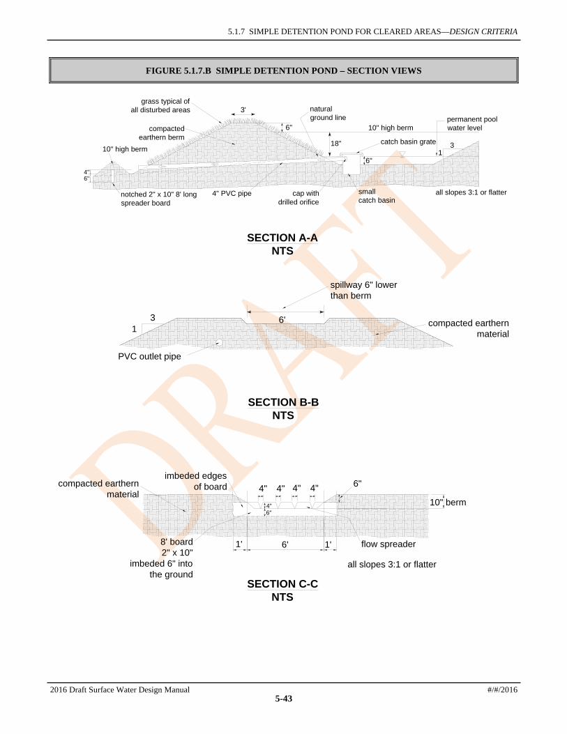
FIGURE 5.1.7.B SIMPLE DETENTION POND – SECTION VIEWS
4" 4" 4" 4"
4"6"
flow spreader
10" berm
8' board2" x 10"
imbeded 6" intothe ground
imbeded edgesof boardcompacted earthern
material
all slopes 3:1 or flatter
6'1' 1'
6"
SECTION C-CNTS
SECTION B-BNTS
6'
spillway 6" lowerthan berm
PVC outlet pipe
31 compacted earthern
material
SECTION A-ANTS
10" high berm
notched 2" x 10" 8' longspreader board
4" PVC pipe cap withdrilled orifice
small catch basin
all slopes 3:1 or flatter
10" high berm
catch basin grate
naturalground line
grass typical ofall disturbed areas 3'
6"
18"
6"4"6"
31
permanent poolwater levelcompacted
earthern berm
2016 Draft Surface Water Design Manual #/#/2016
5-43

SECTION 5.1 DETENTION FACILITIES
5.1.7.2 METHODS OF ANALYSIS The detention volume and orifice sizing for the simple detention pond shall be determined as described in this section. This determination is based on where the pond is located within the County and how much cleared area (i.e., area of forest converted to pasture or grass) is served by the pond.
Detention Volume The map in Figure 5.1.7.C (p. 5-45) provides the minimum pond volume required based on 10,000 square feet of cleared area. To determine the total pond volume required, locate the project site on the map and multiply the number from the map by the amount of cleared area that will be served by the pond (if the cleared area is measured in units of square feet, remember to divide the actual area by 10,000 before multiplying with map value). If the project site is located between the lines shown on the map, select the larger of the two pond unit volumes associated with the lines. Do not interpolate the volume if located midway between two lines.
To determine if the constructed pond has adequate storage, the pond area must be determined by field measurements. If all side slopes are at 3H:1V or flatter, the pond's bottom area may be used to determine the pond volume, Vt, above the permanent pool using the following equation. The resulting volume, Vt, must be equal to or greater than the required volume determined from Figure 5.1.7.C.
Vt = 1.5 Ab + 3.4 P (5-9)
where Vt = total pond volume available (cu ft) Ab = bottom area of pond (sq ft) P = bottom perimeter of pond (ft)
A more accurate volume determination can be made with field measurements and area calculations taken at two elevations. The first elevation at which the pond area is measured is at the top of the permanent pool. The second area measurement is taken at the overflow spillway elevation.
Vt = d 2
)( bw AA + (5-10)
where Vt = total pond volume available (cu ft) Aw = area of pond (sq ft) measured at the lowest elevation of the overflow spillway (Ab) Ab = area of pond (sq ft) measured at the top of the permanent pool d = depth of reservoir (ft) = 1.5 feet
Orifice Sizing provides the orifice diameter to be drilled into the PVC cap. If the orifice diameter matches the PVC pipe diameter, no cap is required. Otherwise, the PVC pipe diameter must be greater than the required orifice diameter. Select the orifice diameter based on the cleared area tributary to the pond, interpolating between the values when designing for intermediate tributary acreage.
#/#/2016 2016 Draft Surface Water Design Manual
5-44

5.1.7 SIMPLE DETENTION POND FOR CLEARED AREAS—METHODS OF ANALYSIS
FIGURE 5.1.7.C SIMPLE DETENTION POND - MINIMUM VOLUME
2016 Draft Surface Water Design Manual #/#/2016
5-45
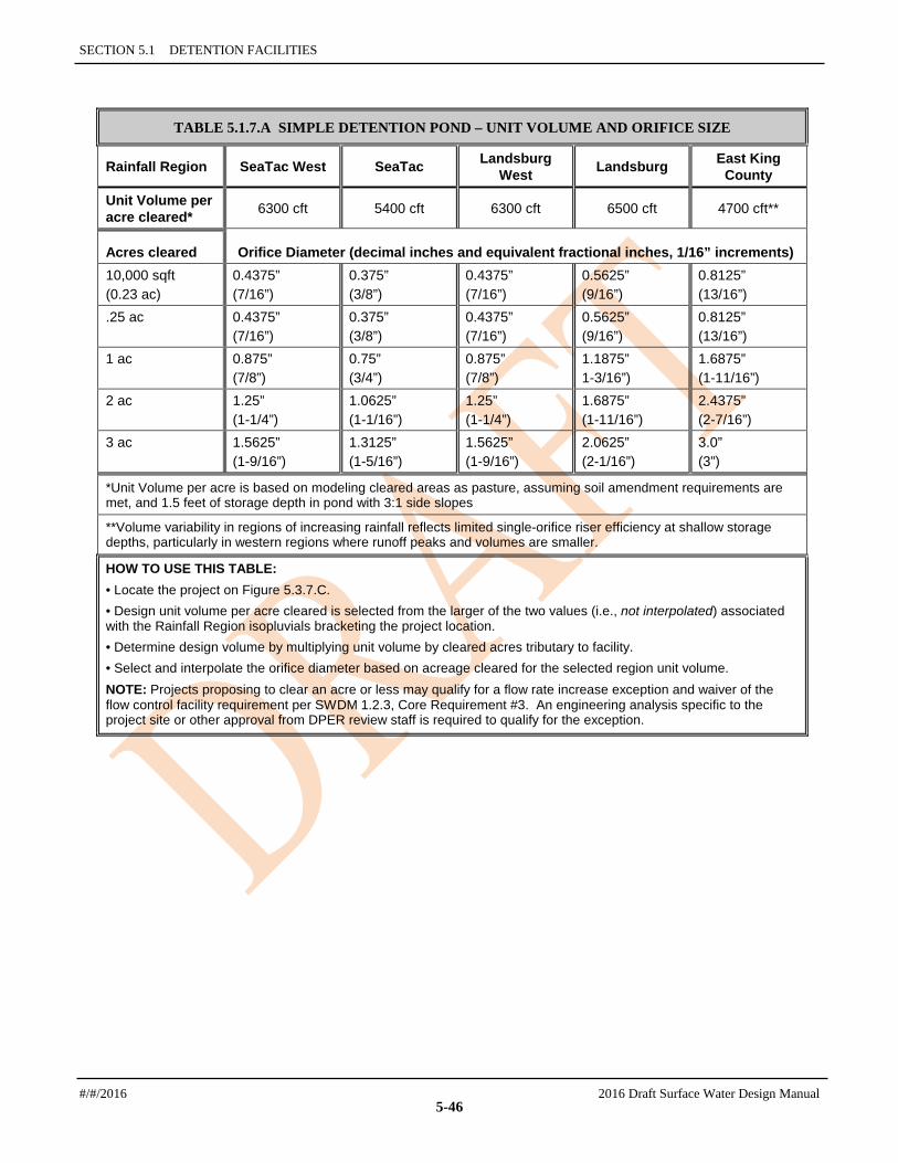
SECTION 5.1 DETENTION FACILITIES
TABLE 5.1.7.A SIMPLE DETENTION POND – UNIT VOLUME AND ORIFICE SIZE
Rainfall Region SeaTac West SeaTac Landsburg West Landsburg East King
County
Unit Volume per acre cleared* 6300 cft 5400 cft 6300 cft 6500 cft 4700 cft**
Acres cleared Orifice Diameter (decimal inches and equivalent fractional inches, 1/16” increments) 10,000 sqft (0.23 ac)
0.4375” (7/16”)
0.375” (3/8”)
0.4375” (7/16”)
0.5625” (9/16”)
0.8125” (13/16”)
.25 ac 0.4375” (7/16”)
0.375” (3/8”)
0.4375” (7/16”)
0.5625” (9/16”)
0.8125” (13/16”)
1 ac 0.875” (7/8”)
0.75” (3/4”)
0.875” (7/8”)
1.1875” 1-3/16”)
1.6875” (1-11/16”)
2 ac 1.25” (1-1/4”)
1.0625” (1-1/16”)
1.25” (1-1/4”)
1.6875” (1-11/16”)
2.4375” (2-7/16”)
3 ac 1.5625” (1-9/16”)
1.3125” (1-5/16”)
1.5625” (1-9/16”)
2.0625” (2-1/16”)
3.0” (3”)
*Unit Volume per acre is based on modeling cleared areas as pasture, assuming soil amendment requirements are met, and 1.5 feet of storage depth in pond with 3:1 side slopes
**Volume variability in regions of increasing rainfall reflects limited single-orifice riser efficiency at shallow storage depths, particularly in western regions where runoff peaks and volumes are smaller.
HOW TO USE THIS TABLE: • Locate the project on Figure 5.3.7.C. • Design unit volume per acre cleared is selected from the larger of the two values (i.e., not interpolated) associated with the Rainfall Region isopluvials bracketing the project location. • Determine design volume by multiplying unit volume by cleared acres tributary to facility. • Select and interpolate the orifice diameter based on acreage cleared for the selected region unit volume. NOTE: Projects proposing to clear an acre or less may qualify for a flow rate increase exception and waiver of the flow control facility requirement per SWDM 1.2.3, Core Requirement #3. An engineering analysis specific to the project site or other approval from DPER review staff is required to qualify for the exception.
#/#/2016 2016 Draft Surface Water Design Manual
5-46

KING COUNTY, WASHINGTON, SURFACE WATER DESIGN MANUAL
5.2 INFILTRATION FACILITIES This section presents the methods, criteria, and details for design and analysis of infiltration facilities. These facilities are used where soils are suitable for soaking the increased runoff from development into the ground. Such facilities usually have a detention volume component to allow for temporary storage of runoff while it is being infiltrated. This detention volume is typically dependent on the infiltration capacity of the soils and the required facility performance.
There are five types of infiltration facilities allowed for use in complying with Core Requirement #3, "Flow Control": infiltration ponds, infiltration tanks, infiltration vaults, infiltration trenches, and small infiltration basins. In general, ponds are preferred because of the ease of maintenance and the water quality treatment that surface soil and vegetation provide. Tanks and trenches are useful where site constraints prevent use of a pond, and small infiltration basins are simple to design but have limited uses.
The information presented in this section is organized as follows:
Section 5.2.1, "General Requirements for Infiltration Facilities"
Section 5.2.2, "Infiltration Ponds" "Design Criteria," Section 5.2.2.1 (p. 5-58) "Methods of Analysis," Section 5.2.2.2 (p. 5-59)
Section 5.2.3, "Infiltration Tanks" "Design Criteria," Section 5.2.3.1 (p. 5-61) "Methods of Analysis," Section 5.2.3.2 (p. 5-62)
Section 5.2.4, "Infiltration Vaults" "Design Criteria," Section 5.2.4.1 (p. 5-64) "Methods of Analysis," Section 5.2.4.2 (p. 5-65)
Section 5.2.5, "Infiltration Trenches" "Design Criteria," Section 5.2.5.1 (p. 5-66) "Methods of Analysis," Section 5.2.5.2 (p. 5-67)
Section 5.2.7, "Small Infiltration Basins" "Design Criteria," Section 5.2.7.1 (p. 5-70).
5.2.1 GENERAL REQUIREMENTS FOR INFILTRATION FACILITIES This section presents the design requirements generally applicable to all infiltration facilities. Included are the general requirements for determining acceptable soil conditions, determining infiltration rates, and providing overflow protection, spill control, presettling, groundwater protection, protection from upstream erosion, and construction.
SOILS The applicant must demonstrate through infiltration testing, soil logs, and the written opinion of a geotechnical engineer that sufficient permeable soil exists at the proposed facility location to allow construction of a properly functioning infiltration facility.
At a minimum, test pits or borings shall extend 5 feet below the bottom of the infiltration facility, and at least one test hole should reach the water table. If the water table is very deep, the test hole need not extend more than one-fourth the maximum width of the pond below the bottom of a pond, or more than 5
2016 Draft Surface Water Design Manual #/#/2016
5-47

SECTION 5.2 INFILTRATION FACILITIES
feet below the bottom of a tank. Measurements shall be made during the period when the water level is expected to be at a maximum (usually in late winter or early spring). Projects performing a groundwater mounding analysis may be required to provide more extensive subsurface exploration as described in the “Groundwater Mounding Analysis” section below.
For projects that perform a groundwater mounding analysis, the basic requirement is a minimum of 3 feet of permeable soil below the bottom of the facility (bottom of pond or excavation for tank) and at least 3 feet between the bottom of the facility and the maximum wet-season water table. For projects that do not perform a groundwater mounding analysis as allowed and described in the “Design Infiltration Rate” section below, the basic requirement is a minimum of 5 feet of permeable soil below the bottom of the facility (bottom of pond or excavation for tank) and at least 5 feet between the bottom of the facility and the maximum wet-season water table.
Any requirements associated with impacts to an erosion hazard area, steep slope hazard area, or landslide hazard area should also be addressed in the soil study.
The geotechnical engineer shall provide a report stating whether the location is suitable for the proposed infiltration facility, and shall recommend a design infiltration rate (see "Design Infiltration Rate" below).
MEASURED INFILTRATION RATES Infiltration rate tests are used to help estimate the maximum sub-surface vertical infiltration rate of the soil below a proposed infiltration facility (e.g., pond or tank); an infiltrative BMP serving either more than one lot, 10,000 square feet or more of impervious surface, 3/4 acre or more of pervious surface or 5,000 square feet or more of pollution generating impervious surface; any BMP used to accomplish LID performance criteria (see Section 5.2); or a closed depression. The tests are intended to simulate the physical process that will occur when the facility is in operation; therefore, a saturation period is required to approximate the soil moisture conditions that may exist prior to the onset of a major winter runoff event.
Testing Procedure 1. Excavations shall be made to the bottom elevation of the proposed infiltration facility. The measured
infiltration rate of the underlying soil shall be determined using one of the following: a single ring percolation test using a ring at least 3 feet in diameter (see Reference Section 6-A), or a larger scale Pilot Infiltration Test (PIT) as described in the 2014 Stormwater Management Manual for Western Washington and Reference 6A of this manual. The larger single ring and PIT tests have been shown to more closely match actual full-scale facility performance than smaller test methods.
2. The test hole or apparatus shall be filled with water and maintained at depths above the test elevation for the saturation periods specified for the appropriate test.
3. Following the saturation period, the rate shall be determined in accordance with the specified test procedures, with a head of 6 inches of water.
4. The design engineer shall perform sufficient tests at multiple locations in a proposed facility footprint to determine a representative infiltration rate. At least one test per 1,000 square feet (or fraction thereof ) of proposed facility footprint shall be performed, with a minimum of two tests for each proposed infiltration facility location; and at least 2 tests per acre (minimum of 4 tests) shall be performed for a closed depression. Proposed bioretention swales require a minimum of 1 test per 200 linear feet of swale or 1 test per 1,000 square feet of facility footprint; with a minimum of two tests performed.
5. A minimum of one soils log shall be obtained per 5,000 square feet or fraction thereof (plan view area) of proposed infiltration surface area (i.e., area at the bottom of the facility), with minimums of two tests for each tank and one test for other facilities. A minimum of one soils log shall be obtained per 200 linear feet of bioretention swale. Additional tests shall be obtained as necessary to capture significant soil variations in the facility footprint. Soils shall be logged for a minimum of 5 feet below the bottom of each proposed infiltration facility. The logs shall describe the SCS series of the soil,
#/#/2016 2016 Draft Surface Water Design Manual
5-48

5.2.1 GENERAL REQUIREMENTS FOR INFILTRATION FACILITIES
indicate the textural class of the soil horizons throughout the depth of the log, note any evidence of high groundwater level (such as mottling), and estimate the maximum groundwater elevation, if within the limits of the log.
DESIGN INFILTRATION RATE In the past, many infiltration facilities have been built that have not performed as the designer intended. This has resulted in flooding and substantial public expenditures to correct problems. Monitoring of actual facility performance has shown that the full-scale infiltration rate is far lower than the rate determined by small-scale testing. Actual measured facility rates of 10% of the small-scale test rate have been seen. It is clear that great conservatism in the selection of design rates is needed, particularly where conditions are less than ideal.
The design infiltration rate determination shall include a groundwater mounding evaluation using an analytical groundwater model to investigate the effects of the local hydrologic conditions on facility performance. Groundwater modeling will not be required for facilities serving less than 1 acre of tributary area and where there is at least 5 feet of separation between the bottom of the proposed facility and the maximum seasonal groundwater table or low permeability stratum, unless requested by DPER review staff, or as part of an analysis in the event of facility failure at performance testing. A ground water mounding analysis is advisable for facilities with drainage areas smaller than 1 acre if the depth to a low permeability layer (e.g., less than 0.1 inches per hour) is less than 10 feet. If the ground water in the area is known to be greater than 50 feet below the proposed facility, detailed investigation of the ground water regime for flow control design is not necessary.
The preliminary design infiltration rate is determined by applying correction factors to the measured infiltration rate. The correction factors account for uncertainties in testing, depth to the water table or impervious strata, infiltration receptor geometry, and long-term reductions in permeability due to biological activity and accumulation of fines. Equation 5-9 has been developed to account for these factors. This equation estimates the maximum design infiltration rate (Idesign); additional reduction in rate beyond that produced by the equation may be appropriate. Note that the design infiltration rate Idesign must not exceed 20 inches/hour.
Idesign = Imeasured x Ftesting x Fgeometry x Fplugging (5-11)
Correction factor Ftesting accounts for uncertainties in the testing methods. For the Pilot Infiltration Test (PIT) or Single Ring Percolation Test (See Reference 6A), Ftesting = 0.50.
When expanding an existing infiltration facility, the historical full-scale infiltration performance of the existing facility may be considered in lieu of the testing procedures above. However, determination of Ftesting for the expanded facility shall include consideration of the existing facility and site characteristics, existing infiltration performance relative to the original design, facility maintenance and site maintenance history, and any other factors influencing the performance of the existing facility. A value for Ftesting between 0.5 and 1.0, as determined by DPER review staff, reflecting the existing facility history shall be applied to the historical full-scale measured infiltration rate.
Fgeometry accounts for the influence of facility geometry and depth to the water table or impervious strata on the actual infiltration rate. A shallow water table or impervious layer will reduce the effective infiltration rate of a large pond, but this will not be reflected in a small scale test. Clearly, a large pond built over a thin pervious stratum with a shallow water table will not function as well as the same pond built over a thick pervious stratum with a deep water table. Fgeometry must be between 0.25 and 1.0 as determined by the following equation:
Fgeometry = 4 D/W + 0.05 (5-12)
2016 Draft Surface Water Design Manual #/#/2016
5-49

SECTION 5.2 INFILTRATION FACILITIES
where D = depth from the bottom of the proposed facility to the maximum wet-season water table or nearest impervious layer, whichever is less
W = width of the facility
Note: When conducting a mounding analysis, apply Fgeometry in the mounding analysis only if facility geometry is not captured in the groundwater model inputs. Include Fgeometry in the design rate determination for the facility
Fplugging accounts for reductions in infiltration rates over the long term due to plugging of soils. This factor is:
• 0.7 for loams and sandy loams
• 0.8 for fine sands and loamy sands
• 0.9 for medium sands
• 1.0 for coarse sands or cobbles, or any soil type in an infiltration facility preceded by a water quality facility.
For bioretention facilities used to meet the LID Performance Standard, a default design rate of 1.5 inches per hour or 3 inches per hour may be used for the standard bioretention soil mix cited in Reference 11-C. 1.5 inches per hour is used where the drainage area to the bioretention device exceeds any of the following:
• 10,000 sq. ft. of impervious surface
• 5,000 sq. ft. of pollution-generating impervious surface
• 3/4 acre of pervious surface
Use 3 inches per hour if the drainage area does not exceed any of the above-listed areas.
The design rate of the in situ soils underlying the bioretention soil mix shall be the measured infiltration rate multiplied by a correction factor ranging from 0.33 to 1 as recommended by a licensed geotechnical engineer or engineering geologist. The selected correction factor should be based on the number of tests in relation to the size of the bioretention facility and site variability.
For permeable pavement used to meet the LID Performance Standard, the design rate of the in situ soils underlying the permeable pavement shall be the measured infiltration rate multiplied by a correction factor ranging from 0.33 to 1 (no correction) as recommended by a licensed geotechnical engineer or engineering geologist. The selected correction factor should be based on the number of tests in relation to the size of the bioretention facility and site variability. A further correction factor of 0.9 to 1 (no correction) is determined based on the quality of the aggregate base material. A correction factor of 1 for the quality of pavement aggregate base material is allowable if the aggregate base is clean washed material with 1% or less fines passing the 200 sieve.
GROUNDWATER MOUNDING ANALYSIS Groundwater mounding analysis is generally required for infiltration facilities that serve 1 acre or more of tributary area and have less than 15 feet of separation to a restrictive layer or groundwater table, as described in the “Design Infiltration Rate” section above.
Groundwater modeling (mounding analysis) of the proposed infiltration facility shall be done using the design infiltration rate (i.e., reduction factors applied to the measured rate) modified to exclude the correction factor for geometry (Fgeometry ) and the estimated maximum groundwater elevation determined for the proposed facility location. It is assumed the groundwater mounding model inputs will capture the facility geometry for the analysis, however if this is not true for the chosen model, the correction factor for geometry shall be included in the infiltration rate. MODRET or an equivalent model must be used unless DPER approves an alternative analytic technique.
#/#/2016 2016 Draft Surface Water Design Manual
5-50

5.2.1 GENERAL REQUIREMENTS FOR INFILTRATION FACILITIES
Developed condition hydrographs of the project site shall be exported from the approved model for the groundwater mounding analysis. Hydrographs for the mounding analysis input shall include, at a minimum, the complete water year (October 1 through September 30) records containing a) the 100-yr peak rate event and b) the cumulative highest 30-day volume event identified through analysis of the developed condition runoff (the two events are usually in different water years). The peak rate water year is readily determined from the flow frequency analysis in the approved model. The cumulative highest 30-day volume analysis can be completed in a spreadsheet using the developed condition hydrograph for the full historical record exported from the approved model. Due to model limitations on the size of the input files, a 1-hour timestep shall be used to generate the hydrographs to be exported, unless otherwise required by DPER staff.
The exported hydrograph file will require minor modification in preparation for import into the groundwater model; see the specific model’s documentation for guidance (MODRET file preparation for hydrograph input is described in the appendix for the software user’s guide). See Reference 8-D for modeling guidelines specific for use with the SWDM.
Note that an iterative process may be required beginning with an estimated design rate, facility sizing with the approved runoff model, then groundwater model testing.
The mounding analysis report shall be included in the Special Reports section of the technical information report (TIR, see Section 2.3.1.1). All mounding analysis submittals shall have at least the following information in one package:
• Test pit and boring logs, including actual elevations used on the design plans (not just relative elevations) documenting subsurface explorations to a depth below the base of the infiltration facility of at least 5 times the maximum design depth of ponded water proposed for the infiltration facility, but not less than 10 feet below the base of the facility. At sites with shallow ground water (less than 15 feet from the estimated base of facility), if a ground water mounding analysis is necessary, determine the thickness of the saturated zone. Note that documentation of the thickness and location of the saturated zone can generally be beneficial to mounding analysis results.
Logs must include at a minimum, depth of pit or hole, soil descriptions, depth to ground water table and/or bedrock/impermeable layers, presence of stratification. (Note: Logs must substantiate whether stratification does or does not exist. The licensed professional may consider additional methods of analysis to substantiate the presence of stratification that will significantly impact the design of the infiltration facility).
• Continuous sampling (representative samples from each soil type and/or unit within the infiltration receptor) to a depth below the base of the infiltration facility of 2.5 times the maximum design ponded water depth, but not less than 10 feet. For large infiltration facilities serving drainage areas of 10 acres or more, perform soil grain size analyses on layers up to 50 feet deep (or no more than 10 feet below the water table).
• Map showing location of test pits, borings and infiltration facility
• Wet season (October 1 to April 30) maximum water table elevation. Monitoring through at least one wet season is required, unless substantially equivalent site historical data regarding ground water levels is available.
• If mottling or iron oxide staining is present, and that elevation does not reflect the wet season maximum water table elevation, include a detailed justification.
• Description and documentation supporting all modeling input parameters
• LS stamped letter documenting constructed volume, elevations, infiltration area (constructed facilities only)
• PE stamped letter documenting TIR volume, elevations and infiltration area (design reviews only)
2016 Draft Surface Water Design Manual #/#/2016
5-51
SECTION 5.2 INFILTRATION FACILITIES
• PE stamped letter (may be the same letter as the previous bullet) documenting rainfall data and infiltration rate determination used in the analysis. Rainfall data shall be at a minimum, the complete water year (October 1 through September 30) records containing a) the 100-yr peak rate event and b) the cumulative highest volume event identified through analysis of the developed condition runoff, both using 1-hour timesteps minimum. Infiltration rate description shall include the initial measured rate and details of the reduction factors applied per Section 5.2.1, Design Infiltration Rate.
• Actual rainfall data (electronic files prepared for model input) used in the mounding analysis modeling runs.
• Separate model runs for the peak rate and highest 30-day cumulative volume periods (two runs unless the events occur in the same water year).
• Justifications for safety factors applied to the infiltration rate applied in the modeling.
• Geotechnical Engineer summary and conclusions
• Small scale infiltration test data (inches/hour) with calibration factor for test type, then converted to Vertical Hydraulic Conductivity (feet/day)
• Geotechnical engineer documentation of why a particular Horizontal Hydraulic Conductivity to Vertical Hydraulic Conductivity (HHC: VHC) ratio is applicable. Without detailed justification, King County will accept for MODRET input an HHC:VHC ratio of 1.5:1 for homogeneous soils and 3:1 for layered soils. Note, however, the vertical conductivity input KVU is for the unsaturated condition (typical of small-scale or PIT test results), while the horizontal conductivity input KHS is for the saturated condition.
Alternatively, if small-scale or PIT is the only test information available, the saturated horizontal hydraulic conductivity could be estimated by applying two adjustment factors as follows5:
KVS (vertical, saturated) = 1.5 KVU (vertical, unsaturated)
KHS (horizontal, saturated) = 1.5 KVS (vertical, saturated).
PERFORMANCE TESTING Performance testing and verification for a facility shall be conducted before final construction approval by King County, or prior to construction of other project improvements or recording of a subdivision as required by KCC 9.04.090 and Public Rule,
For projects where a mounding analysis is not required at the design phase (i.e., facilities serving less than 1 acre of tributary area and where there is at least 5 feet of separation between the bottom of the proposed facility and the maximum seasonal groundwater table or low permeability stratum),the completed facility must be tested and monitored to demonstrate that the facility performs as designed. If the facility performance is not satisfactory, the facility will need to be modified or expanded as needed in order to make it function as designed.
Where a groundwater mounding analysis was used in the design, performance testing and verification in the bottom of the facility to demonstrate that the soils in the constructed facility are representative of the design assumptions is required. The evaluation shall include measured infiltration rate testing and evaluation of in-situ soil characteristics and groundwater table location as described in this section. The measured infiltration rate test procedure should follow the same methodology as during the design phase to be comparable. If the facility performance evaluation is not satisfactory, the facility will need to be modified or expanded as needed in order to make it function as designed.
5 Source: State of Florida Dept. of Transportation, Stormwater Management Facility Drainage Handbook, Jan 2004, p.70 #/#/2016 2016 Draft Surface Water Design Manual
5-52

5.2.1 GENERAL REQUIREMENTS FOR INFILTRATION FACILITIES
100-YEAR OVERFLOW CONVEYANCE An overflow route shall be identified for stormwater flows that overtop the facility when infiltration capacity is exceeded or the facility becomes plugged and fails. The overflow route must be able to safely convey the 100-year developed peak flow to the downstream conveyance system or other acceptable discharge point in accordance with conveyance requirements in Section 1.2.4.
Where the entire project site is located within a closed depression (such as some gravel pits), the requirement to identify and analyze a 100-year overflow pathway may be waived by DPER if (1) an additional correction factor of 0.5 is used in calculating the design infiltration rate, (2) the facility is sized to fully infiltrate the 100-year runoff event, and (3) the facility is not bermed on any side. Intent: to address situations where the infiltration facility may be a highly permeable onsite closed depression, such as a gravel pit, where all stormwater is currently, and will remain, fully infiltrated.
SPILL CONTROL DEVICE All infiltration facilities must have a spill control device upstream of the facility to capture oil or other floatable contaminants before they enter the infiltration facility. The spill control device shall be a tee section per Figure 5.1.4.A (p. 5-29) or an equivalent device approved by DPER. If a tee section is used, the top of the riser shall be set above the 100-year overflow elevation to prevent oils from entering the infiltration facility.
PRESETTLING Presettling must be provided before stormwater enters the infiltration facility. This requirement may be met by either of the following:
• A water quality facility from the Basic WQ menu (this alternative is recommended; see Section 6.1.1 for facility options).
• A presettling pond or vault with a treatment volume equal to 0.25 times the basic water quality design volume (see Section 6.4.1.1 for information on computing this volume).
If water in the WQ facility or presettling facility will be in direct contact with the soil, the facility must be lined according to the liner requirements in Section 6.2.4. If the presettling facility is a vault, design of the vault shall be the same as required for presettling cells in sand filter vaults (see Section 6.5.3.2).
The settling pond or vault shall be designed to pool water 4 to 6 feet deep with an overflow capacity sufficient to pass the developed 100-year peak flow. Settling facilities must have a length-to-width ratio of at least 3:1. The inlet(s) and outlet should be situated to maximize the length of travel through the settling pond or vault. Berms or baffles may be used to lengthen the travel distance if site constraints limit the inlet/outlet placement. Inlets should be designed to minimize velocity and turbulence. Roof runoff need not be treated before entering an infiltration facility.
PROTECTION FROM UPSTREAM EROSION Erosion must be controlled during construction of areas upstream of infiltration facilities since sediment-laden runoff can permanently impair the functioning of the system. Erosion control measures must be designed, installed and maintained with great care. Various strategies may be employed to protect infiltration facilities during construction, as described below.
Projects may be phased to limit clearing and minimize the time that soils are exposed. An alternative to this approach is to serve the undeveloped area with a large sediment trap on an undeveloped tract with the trap left in place until all clearing and construction is complete and all permanent landscaping is in place. See Erosion and Sediment Control Standards (detached Appendix D) for design details. At the completion of all construction, the sediment trap must be cleaned out (taking care that no sediment enters the drainage system) and filled in, and the flow routed to the permanent drainage system.
Another alternative for subdivisions is to stage excavation of the pond as follows: 2016 Draft Surface Water Design Manual #/#/2016
5-53

SECTION 5.2 INFILTRATION FACILITIES
1. Bottom elevation of the pond prior to paving of plat roadways: 3 feet above the final pond bottom elevation. At this stage of rough grading, the facility may be used to meet sediment retention requirements.
2. Bottom elevation of the pond during and after paving and prior to construction of 80% of the houses: 18 inches above the final pond bottom elevation with upstream sediment retention, as needed. At this stage, the pond will serve as an interim flow control facility pending final stabilization of the site. Note that KCC 9.04.090 requires that flow control facilities be operational prior to the construction of any improvements.
FACILITY CONSTRUCTION GUIDELINES Excavation of infiltration facilities should be done with a backhoe working at "arms length" to minimize disturbance and compaction of the completed infiltration surface. If the bottom of the facility will be less than three feet below final grade, the facility area should be cordoned off so that construction traffic does not traverse the area. The exposed soil should be inspected by a soils engineer after excavation to confirm that soil conditions are suitable.
Two simple staff gages for measuring sediment depth should be installed at opposite ends of the bottom of ponds. The gages may consist of 1-inch pipe driven at least one foot into the soil in the bottom of the pond, with 12 inches of the pipe protruding above grade.
OFFSITE GROUNDWATER LEVEL IMPACTS Potential impacts to groundwater levels off the project site should be considered. In general, replacing vegetation with impervious cover will increase the total annual volume of runoff generated on a site. Infiltrating this runoff will tend to increase ground water recharge, which may affect groundwater levels offsite. The impacts of infiltration could include increased water to landslide hazard areas, increased groundwater resources available, increased water levels in closed depressions, and higher groundwater levels. Higher groundwater levels offsite could result in increased flooding of basements, or impaired functioning of infiltration systems resulting in surface water flooding. Evidence of offsite groundwater flooding problems should be examined during the offsite analysis required under Core Requirement #2 (see Section 1.2.2).
In general, groundwater level impacts will be very difficult to reduce, and there are no specific requirements that apply in many cases. The design engineer is encouraged to consider whether there are any feasible approaches to reduce groundwater flooding impacts, such as moving facilities or changing facility geometry, retaining forest cover, minimizing impervious coverage, or fixing downstream problems.
GROUNDWATER PROTECTION The protection of groundwater quality is recognized as an issue of importance equal to surface water quality. Safeguards are required to avoid contaminating groundwater. The applicant should check the Critical Aquifer Recharge (CARA) map, sole source aquifer designations, and wellhead protection areas and/or 1, 5 and 10 year time of travel zones for municipal well protection areas (if available), mapped by the Washington State Department of Health, to determine if the project lies within a groundwater protection area.
The groundwater protection requirements of this manual set forth in Chapter 1 call for implementing one of the following actions when infiltrating runoff from pollution-generating surfaces:
1) For industrial sites, provide water quality treatment prior to infiltration as specified in Core Requirement #8 and Special Requirement #5.
2) For projects infiltrating within ¼ mile of a sensitive lake, provide water quality treatment prior to infiltration as specified in Core Requirement #8 and Special Requirement #5.
3) For all other sites:
#/#/2016 2016 Draft Surface Water Design Manual
5-54

5.2.1 GENERAL REQUIREMENTS FOR INFILTRATION FACILITIES
a) Provide water quality treatment prior to infiltration as specified in Core Requirement #8 and Special Requirement #5, OR
b) Demonstrate that the soil beneath the infiltration facility has properties that reduce the risk of groundwater contamination from typical stormwater runoff. Such properties are defined in below and are dependent on whether the project is located outside of or within a groundwater protection area.
Soil Properties Required for Groundwater Protection Soil properties required for groundwater protection both outside of and within groundwater protection areas . Groundwater protection areas include but are not limited to critical aquifer recharge areas (CARAs), wellhead protection areas or zones (including 1, 5 and 10 year time of travel zones for municipal well protection areas, if available), and sole source aquifers.
Note: The soil properties given are primarily for groundwater protection and do not necessarily satisfy other protection needs. For example, projects infiltrating runoff within a quarter-mile of a Sensitive Lake may still be required to provide water quality treatment to meet the resource protection needs of the Sensitive Lake. See Core Requirement #8 (Section 1.2.8) for additional WQ requirements.
Soil Properties Required for Groundwater Protection Outside of Groundwater Protection Areas For infiltration facilities located outside of groundwater protection areas, acceptable groundwater protection is provided by the soil if the first two feet or more of the soil beneath the infiltration facility has a cation exchange capacity6 greater than 5 and an organic content7 of 1.0% or greater, AND meets one of the following criteria:
a) The soil has a measured infiltration rate less than or equal to 9 inches per hour8 or is logged as one of the classes from the USDA Textural Triangle (Figure 5.2.1.A,), excluding sand and loamy sand (Note: soil texture classes other than sand and loamy sand may be assumed to have an infiltration rate of less than or equal to 9 inches per hour without doing field testing to measure rates.9), OR
b) The soil is composed of less than 25% gravel by weight with at least 75% of the soil passing the #4 sieve. The portion passing the #4 sieve must meet one of the following gradations:
• At least 50% must pass the #40 sieve and at least 2% must pass the #100 sieve, or
• At least 25% must pass the #40 sieve and at least 5% must pass the #200 sieve.
Note: These soil properties must be met by the native soils onsite. Soil may not be imported in order to meet groundwater protection criteria without an approved adjustment.
6 Cation exchange capacity shall be tested using EPA Laboratory Method 9081. Note that per EPA method 9081 guidance, distinctly acidic soils require “the method of cation-exchange capacity by summation (Chapman, 1965, p. 900; see Paragraph 10.1)”.
7 Organic content shall be measured on a dry weight basis using method ASTM D2974 for the fraction passing the #40 sieve. 8 See discussion of the measured infiltration rate in Section 5.2.1. 9 Criteria (a) is based on the relationship between infiltration rates and soil texture. However, there are many other factors, such
as high water table, presence of impervious strata or boulders close to the surface, etc., which also affect infiltration rate. When any such condition is suspected because soils are coarser than expected from the measured infiltration rate, a sieve analysis should be done to establish soil characteristics. The judgment of a geotechnical engineer, geologist or soil scientist shall determine whether a sieve analysis is warranted. The sieve analysis must meet Criteria (b) above to be considered protective.
2016 Draft Surface Water Design Manual #/#/2016
5-55

SECTION 5.2 INFILTRATION FACILITIES
Soil Properties Required within Groundwater Protection Areas For projects located within groundwater protection areas, acceptable groundwater protection is provided by the soil if the first two feet or more of the soil beneath the infiltration facility has a cation exchange capacity greater than 5 and an organic content of 1% or greater, AND meets one of the following criteria:
a) The soil has a measured infiltration rate less than or equal to 2.4 inches per hour or is logged as one of the classes from the USDA Textural Triangle (Figure 5.2.1.A, p. 5-56), excluding sand, loamy sand, and sandy loam (Note: soil triangle texture classes other than sand, loamy sand, and sandy loam may be assumed to have an infiltration rate of less than or equal to 2.4 inches per hour without doing field testing to measure rates.10), OR
b) The soil has a measured infiltration rate less than or equal to 9 inches per hour, and it must be composed of less than 25% gravel by weight with at least 75% of the soil passing the #4 sieve. The portion passing the #4 sieve must meet one of the following gradations:
• At least 50% must pass the #40 sieve and at least 2% must pass the #100 sieve, or
• At least 25% must pass the #40 sieve and at least 5% must pass the #200 sieve.
Note: The above soil properties must be met by the native soils onsite. Soil may not be imported in order to meet groundwater protection criteria without an approved adjustment.
FIGURE 5.2.1.A USDA TEXTURAL TRIANGLE
Infiltration near Water Supply Wells The design engineer should consider the following when designing infiltration facilities near water supply wells:
11See Section 5.2.1 and Reference 6 for Underground Injection Control definition and UIC well registration requirements for infiltration vaults
#/#/2016 2016 Draft Surface Water Design Manual
5-56
5.2.1 GENERAL REQUIREMENTS FOR INFILTRATION FACILITIES
1. In no case should infiltration facilities be placed closer than 100 feet from drinking water wells and 200 feet from springs used for drinking water supplies. Where water supply wells exist nearby, it is the responsibility of the applicant's engineer to locate such wells, meet any applicable protection standards, and assess possible impacts of the proposed infiltration facility on groundwater quality. If negative impacts on an individual or community water supply are possible, additional runoff treatment must be included in the facility design, or relocation of the facility should be considered.
2. All infiltration facilities located within the one-year capture zone of any well should be preceded by a water quality treatment facility.
Infiltration near Steep Slopes and Landslide Hazard Areas The following restrictions apply to the design of infiltration systems located near a slope steeper than 15%.
1. Where infiltration facilities are proposed within 200 feet of a steep slope hazard area or a landslide hazard area, OR closer to the top of slope than the distance equal to the total vertical height of a slope area that is steeper than 15%, a detailed geotechnical evaluation is required. The geotechnical analysis must consider cumulative impacts from the project and surrounding areas under full built- out conditions.
2. Individual lot infiltration and dispersion systems rather than a centralized infiltration facility should be used to the extent feasible, except for lots immediately adjacent to a landslide hazard area. The runoff from such lots should be discharged into a tightline system, if available, or other measures should be implemented as recommended by a geotechnical engineer, engineering geologist, or DPER staff geologist.
UNDERGROUND INJECTION CONTROL WELL REGISTRATION The Underground Injection Control Program (UIC) administered by WA Ecology protects groundwater quality by regulating discharges to UIC wells. WA Ecology adopted revisions to Chapter 173-218 WAC, the Underground Injection Control (UIC) program rules, on January 3, 2006. The newly adopted revisions went into effect on February 3, 2006. These rules require the registration of new injection wells that manage stormwater. Information regarding these new regulations may be found at Ecology's Underground Injection Control Program website, http://www.ecy.wa.gov/programs/wq/grndwtr/uic/index.html.
UIC wells are manmade structures used to discharge fluids into the subsurface. Examples are drywells, infiltration trenches with perforated pipe, and any structure deeper than the widest surface dimension (see Reference 6 or Ecology’s UIC Program website for the Underground Injection Control (UIC) Program Class V Well Identification Guide provided by WA Ecology). In general, infiltration systems that have buried pipe, tanks, or vaults would be considered injection wells, but systems managing runoff only from single-family or duplex roofs, or used to control basement flooding, are exempt. Open ponds are not considered injection wells.
Underground Injection Control (UIC) Program rule requirements apply to all UIC wells. If an existing UIC well receives stormwater and was in use before 2/3/2006, the well owner must complete a well assessment with Ecology to determine if the UIC well is a high threat to groundwater. See Chapter 173-218-090 (2) WAC UIC Program, http://app.leg.wa.gov/WAC/default.aspx?cite=173-218-090 or visit http://www.ecy.wa.gov/programs/wq/grndwtr/uic/UICwellassessment.html for more information.
Note that existing UIC wells that are unable to obtain Ecology rule authorization and UIC Site ID number without modification may require design review and permit approval per King County requirements for such modifications. Permitting for the modified facility shall follow the UIC registration requirements guidance for new facilities.
2016 Draft Surface Water Design Manual #/#/2016
5-57

SECTION 5.2 INFILTRATION FACILITIES
5.2.2 INFILTRATION PONDS Infiltration ponds may be constructed by excavating or constructing berms. See Figure 5.2.2.A (p. 5-60) for a typical detail.
5.2.2.1 DESIGN CRITERIA
General The following criteria for ponds are in addition to the general requirements for infiltration facilities specified in Section 5.2.1:
1. The proposed pond bottom must be at least 3 feet above the seasonal high groundwater level and have at least 3 feet of permeable soil beneath the bottom.
2. Infiltration ponds are not allowed on slopes greater than 25% (4H:1V). A geotechnical analysis and report is required if located within 200 feet of a steep slope hazard area or landslide hazard area OR if the facility is located within a setback distance from top of slope equal to the total vertical height of a slope area that is steeper than 15%. The geotechnical analysis must consider cumulative impacts from the project and surrounding areas under full built- out conditions.
3. The infiltration surface must be in native soil (excavated at least one foot in depth).
4. Maintenance access shall be provided to both the presettling pond or vault (if provided) and the infiltration pond.
5. An overflow structure such as that shown in Figure 5.1.1.C (p. 5-17) shall be provided. In addition, infiltration ponds shall have an emergency spillway as required for detention ponds in Section 5.1.1.1 (p. 5-6).
6. The criteria for general design, side slopes, embankments, planting, maintenance access, access roads, fencing, signage, and right-of-way shall be the same as for detention ponds (see Section 5.1.1, p. 5-5), except as required for the infiltration design.
Setbacks 1. The toe of the exterior slope of an infiltration pond berm embankment shall be set back 5 feet from
the tract, easement, or property line.
2. The tract, easement, or property line on an infiltration pond cut slope shall be set back 5 feet from the emergency overflow water surface.
3. The infiltration pond design water surface shall be set back 100 feet from proposed or existing septic system drainfields. This setback may be reduced to 30 feet with approval from the Seattle - King County Department of Public Health.
4. The infiltration pond design water surface shall be a minimum of 200 feet from any steep slope hazard area or landslide hazard area. Upon analysis and approval of a licensed geotechnical engineer or engineering geologist, this setback may be reduced to 50 feet. The geotechnical analysis must consider cumulative impacts from the project and surrounding areas under full built- out conditions.
5. The infiltration pond design water surface shall be set back a minimum distance from top of slope equal to the total vertical height of a slope area that is steeper than 15%. Upon analysis and approval of a licensed geotechnical engineer or engineering geologist, this setback may be reduced to 50 feet. The geotechnical analysis must consider cumulative impacts from the project and surrounding areas under full built- out conditions.
#/#/2016 2016 Draft Surface Water Design Manual
5-58
5.2.2 INFILTRATION PONDS
6. Building setback lines for adjacent internal lots shall be 20 feet. These may be reduced to the minimum allowed by zoning if the facility soils report addresses the potential impacts of the facility phreatic surface on structures so located.
7. The infiltration pond design water surface shall be set back 20 feet from external tract, easement or property lines. This may be reduced to 5 feet if the facility soils report addresses the potential impacts of the facility phreatic surface on existing or future structures located on adjacent external lots.
5.2.2.2 METHODS OF ANALYSIS The size of the pond shall be determined using the hydrologic analysis and routing methods described for detention ponds in Chapter 3. The storage volume in the pond is used to detain runoff prior to infiltration. The stage/discharge curve shall be developed from the design infiltration rate determined according to Section 5.2.1 (p. 5-47). At a given stage the discharge may be computed using the area of pervious surface through which infiltration will occur (which will vary with stage) multiplied by the recommended design infiltration rate (in appropriate units). Berms (which should be constructed of impervious soil such as till), maintenance access roads, and lined swales should not be included in the design pervious surface area.
2016 Draft Surface Water Design Manual #/#/2016
5-59

SECTION 5.2 INFILTRATION FACILITIES
FIGURE 5.2.2.A TYPICAL INFILTRATION POND
NOTE:Detail is a schematic representation only. Actual configuration will varydepending on specific site constraints and applicable design criteria.
SECTION A-ANTS
PLAN VIEWoverflow/emergency overflowprovided per Section 5.3.1.1
inflow pipe
access road see Section 5.3.1.1
for specificationstract/easementlines as required
connectingspillway
infiltration pond
emergency overflow spillway
outflow/overflowstructure
see Figure5.3.1.B
5' minimum
for detailssee Figure 5.3.1.B
settling pondif required
3:1 slope (typ)
12'/15' if H>6'(typ)
6' if H<6'
existing ground
#/#/2016 2016 Draft Surface Water Design Manual
5-60

5.2.3 INFILTRATION TANKS
5.2.3 INFILTRATION TANKS Infiltration tanks consist of underground pipe that has been perforated to allow detained stormwater to be infiltrated. Figure 5.2.3.A (p. 5-63) shows a typical infiltration tank.
5.2.3.1 DESIGN CRITERIA
General The following criteria for tanks are in addition to the general requirements for infiltration facilities specified in Section 5.2.1:
1. The proposed tank trench bottom shall be at least 3 feet above the seasonal high groundwater level and have at least 3 feet of permeable soil beneath the trench bottom.
2. Infiltration tanks are not allowed on slopes greater than 25% (4H:1V). A geotechnical analysis and report is required if located within 200 feet of a steep slope hazard area or landslide hazard area OR if the facility is located within a setback distance from top of slope equal to the total vertical height of a slope area that is steeper than 15%. The geotechnical analysis must consider cumulative impacts from the project and surrounding areas under full built- out conditions.The infiltration surface elevation (bottom of trench) must be in native soil (excavated at least one foot in depth).
3. Spacing between parallel tanks shall be calculated using the distance from the lowest trench bottom to the maximum wet season ground water surface (D) and the design width of the trench for a single tank (W). The tank spacing S = W2/D, where S is the centerline spacing between trenches (or tanks) in feet. S shall not be less than W, and S need not exceed 2W.
4. Tanks shall be bedded and backfilled with washed drain rock that extends at least 1 foot below the bottom of the tank, at least 2 feet but not more than 5 feet beyond the sides, and up to the top of the tank.
5. Drain rock (3 to 11/2 inches) shall be completely covered with filter fabric prior to backfilling.
6. The perforations (holes) in the tank must be one inch in diameter and located in the bottom half of the tank starting at an elevation of 6 inches above the invert of the tank. The number and spacing of the perforations should be sufficient to allow complete utilization of the available infiltration capacity of the soils with a safety factor of 2.0 without jeopardizing the structural integrity of the tank.
7. Infiltration tanks shall have an overflow structure equipped with a solid bottom riser (with clean-out gate) and outflow system for safely discharging overflows to the downstream conveyance system or another acceptable discharge point.
8. The criteria for general design, materials, structural stability, buoyancy, maintenance access, access roads, and right-of-way shall be the same as for detention tanks (see Section 5.1.2, p. 5-20), except for features needed to facilitate infiltration.
Setbacks 1. Tanks shall be set back 100 feet from proposed or existing septic system drainfields. This setback
may be reduced to 30 feet with approval from the Seattle - King County Department of Public Health.
2. All tanks shall be a minimum of 200 feet from any steep slope hazard area or landslide hazard area. Upon analysis and approval of a licensed geotechnical engineer or engineering geologist, this setback may be reduced to 50 feet. The geotechnical analysis must consider cumulative impacts from the project and surrounding areas under full built- out conditions.
3. All tanks shall be set back a minimum distance from top of slope equal to the total vertical height of a slope area that is steeper than 15%. Upon analysis and approval of a licensed geotechnical engineer
2016 Draft Surface Water Design Manual #/#/2016
5-61

SECTION 5.2 INFILTRATION FACILITIES
or engineering geologist, this setback may be reduced to 50 feet. The geotechnical analysis must consider cumulative impacts from the project and surrounding areas under full built- out conditions.
4. Building setback lines for adjacent internal lots shall be 20 feet. These may be reduced to the minimum allowed by zoning if the facility soils report addresses the potential impacts of the facility phreatic surface on structures so located.
5. Infiltration tanks shall be set back 20 feet from external tract, easement, or property lines. This may be reduced to 5 feet if the facility soils report addresses the potential impacts of the facility phreatic surface on existing or future structures located on adjacent external lots.
5.2.3.2 METHODS OF ANALYSIS The size of the tank shall be determined using the hydrologic analysis and routing methods described in Chapter 3, and the stage/discharge curve developed from the recommended design infiltration rate as described in Section 5.2.1 (p. 5-47). The storage volume in the tank is used to detain runoff prior to infiltration with the perforations providing the outflow mechanism. At any given stage, the discharge may be computed using the area of pervious surface through which infiltration will occur multiplied by the recommended design infiltration rate (in appropriate units). The area of pervious surface used for determining the potential infiltration from the tank shall be computed by taking the lesser of the trench width, or two times the width of the tank, and then multiplying by the length of the tank (assuming infiltration through the bottom of the trench only).
#/#/2016 2016 Draft Surface Water Design Manual
5-62

5.2.3 INFILTRATION TANKS
FIGURE 5.2.3.A TYPICAL INFILTRATION TANK
NOTES:• All metal parts corrosion resistant. Steel parts galvanized and asphalt coated (treatment 1 or better).• Filter fabric to be placed over washed rock backfill.
overflow structuremin. 54" dia.
type 2 C.B.see Section 5.4.1
outlet pipe
outlet/overflowstructure
2.0' max
washed rock beddingand backfill to top of tank,min. 2' beyond edges
settling vault ortype 2 C.B.if required
optional parallel tank
access risers(max spacing 100-ft)
access riserssee Figure
5.3.2.B
2" min. diameter air ventpipe welded to tank(required if no accessriser on tank)
type 2 C.B. or settlingvault if required
washed rock beddingand backfill to top of tank
filter fabrictop only
50' max 100' max
riser for infiltration onlyfor detention/infiltration
see Figure 5.3.4.A
36" min. dia. (typ.)
detention tanksize as required
4' min.2' min.
1" holes asrequired
6" min. dead storage
PLAN VIEWNTS
SECTION A-ANTS
inlet pipe(flow through)
2016 Draft Surface Water Design Manual #/#/2016
5-63

SECTION 5.2 INFILTRATION FACILITIES
5.2.4 INFILTRATION VAULTS Infiltration vaults consist of a bottomless concrete vault structure placed underground in native infiltrative soils11. Infiltration is achieved through the native soils at the bottom of the structure.
Infiltration vaults are similar to detention vaults. A standard detention vault detail is shown in Figure 5.1.3.A (p. 5-27). Overflow riser details are shown in Section 5.1.4 beginning on page 5-28.
5.2.4.1 DESIGN CRITERIA
General The following criteria for vaults are in addition to the general requirements for infiltration facilities specified in Section 5.2.1:
1. The proposed vault bottom shall be at least 3 feet above the seasonal high groundwater level and have at least 3 feet of permeable soil beneath the bottom.
2. Infiltration vaults are not allowed on slopes greater than 25% (4H:1V). A geotechnical analysis and report is required if located within 200 feet of a steep slope hazard area or landslide hazard area OR if the facility is located within a setback distance from top of slope equal to the total vertical height of the slope area that is steeper than 15%. The geotechnical analysis must consider cumulative impacts from the project and surrounding areas under full built- out conditions.
3. The vault bottom must be in native soil (excavated at least one foot in depth).
4. A suitable means to dissipate energy at the inlet is required to prevent scour and may be accomplished by using the detail for the sand filter vault (see Figure 6.5.3.A).
5. Infiltration vaults shall have a solid bottom riser (with clean-out gate) and outflow system for safely discharging overflows to the downstream conveyance system or another acceptable discharge point.
Structural Stability All vaults shall meet structural requirements for overburden support and H-20 vehicle loading. Vaults located under roadways must meet the live load requirements of the King County Road Design and Construction Standards (KCRDCS). Cast-in-place wall sections shall be designed as retaining walls. Structural designs for vaults must be stamped by a licensed structural engineer unless otherwise approved by DPER. Bottomless vaults shall be provided with footings placed on stable, well-consolidated native material and sized considering overburden support, traffic loading (assume maintenance traffic, if placed outside ROW), and lateral soil pressures when the vault is dry. Infiltration vaults shall not be allowed in fill slopes unless analyzed in a geotechnical report for stability. The infiltration surface at the bottom of the vault must be in native soil.
Access Requirements Same as specified for detention vaults in Section 5.1.3.1 (p. 5-24).
Access Roads Same as specified for detention vaults in Section 5.1.3.1 (p. 5-24).
11See Section 5.2.1 and Reference 6 for Underground Injection Control definition and UIC well registration requirements for infiltration vaults
#/#/2016 2016 Draft Surface Water Design Manual
5-64
5.2.4 INFILTRATION VAULTS
Right-of-Way Infiltration vaults to be maintained by King County but not located in King County right-of-way shall be in a tract dedicated to King County. Any tract not abutting public right-of-way will require a 15-foot wide extension of the tract to accommodate an access road to the vault.
Setbacks 1. Infiltration vaults shall be set back 100 feet from proposed or existing septic system drainfields.
This setback may be reduced to 30 feet with approval from the Seattle - King County Department of Public Health.
2. Infiltration vaults shall be a minimum of 200 feet from any steep slope hazard area or landslide hazard area. Upon analysis and approval of a licensed geotechnical engineer or engineering geologist, this setback may be reduced to 50 feet. The geotechnical analysis must consider cumulative impacts from the project and surrounding areas under full built- out conditions.
3. Infiltration vaults shall be set back a minimum distance from top of slope equal to the total vertical height of a slope area that is steeper than 15%. Upon analysis and approval of a licensed geotechnical engineer or engineering geologist, this setback may be reduced to 50 feet. The geotechnical analysis must consider cumulative impacts from the project and surrounding areas under full built- out conditions.
4.
5. Building setback lines for adjacent internal lots shall be 20 feet. These may be reduced to the minimum allowed by zoning if the facility soils report addresses the potential impacts of the facility phreatic surface on structures so located.
6. Infiltration vaults shall be set back 20 feet from external tract, easement, or property lines. This may be reduced to 5 feet if the facility soils report addresses the potential impacts of the facility phreatic surface on existing or future structures located on adjacent external lots.
5.2.4.2 METHODS OF ANALYSIS The size of the vault shall be determined using the hydrologic analysis and routing methods described in Chapter 3 and the stage/discharge curve developed from the recommended design infiltration rate as described in Section 5.2.1 (p. 5-47). The storage volume in the vault is used to detain runoff prior to infiltration. At any given stage, the discharge may be computed using the area of pervious surface through which infiltration will occur (the exposed soil comprising the vault bottom) multiplied by the recommended design infiltration rate (in appropriate units).
2016 Draft Surface Water Design Manual #/#/2016
5-65
SECTION 5.2 INFILTRATION FACILITIES
5.2.5 INFILTRATION TRENCHES Infiltration trenches can be a useful alternative for developments with constraints that make siting a pond difficult. Infiltration trenches may be placed beneath parking areas, along the site periphery, or in other suitable linear areas.
5.2.5.1 DESIGN CRITERIA
General The following criteria for trenches are in addition to the general requirements for infiltration facilities specified in Section 5.2.1:
1. The proposed trench bottom must be at least 3 feet above the seasonal high groundwater level and 3 feet below finished grade.
2. There must be at least 3 feet of permeable soil beneath the trench bottom.
3. The infiltration surface elevation (bottom of trench) must be in native soil (excavated at least one foot in depth).
4. Infiltration trenches are not allowed on slopes greater than 25% (4H:1V). A geotechnical analysis and report is required if located within 200 feet of a steep slope hazard area or landslide hazard area OR if the facility is located within a setback distance from top of slope equal to the total vertical height of the slope area that is steeper than 15%. The geotechnical analysis must consider cumulative impacts from the project and surrounding areas under full built- out conditions.Trenches shall be a minimum of 2 feet wide and no more than 5 feet wide12.
5. Trenches shall be backfilled with 11/2 - 3/4-inch washed rock, completely surrounded by filter fabric and overlain by a minimum 1 foot of compact backfill.
6. Level 6-inch minimum diameter rigid perforated distribution pipes shall extend the length of the trench. Distribution pipe inverts shall be a minimum of 2 feet below finished grade. Provisions (such as clean-out wyes) shall be made for cleaning the distribution pipe. The pipe capacity shall be calculated to verify that the distribution pipe has capacity to handle the maximum design flow.
7. Alternative trench-type systems such as pre-fabricated bottomless chambers that provide an equivalent system may be used at the discretion of DPER.
8. Two feet minimum cover shall be provided in areas subject to vehicle loads.
9. Trenches shall be spaced no closer than 10 feet, measured on center.
Setbacks 1. Trench systems shall be set back 100 feet from proposed or existing septic system drainfields. This
setback may be reduced to 30 feet with approval from the Seattle - King County Department of Public Health.
2. Trench systems shall be a minimum of 200 feet from any steep slope hazard area or landslide hazard area. Upon analysis and approval of a licensed geotechnical engineer or engineering geologist, this setback may be reduced to 50 feet. The geotechnical analysis must consider cumulative impacts from the project and surrounding areas under full built- out conditions.
3. Trench systems shall be setback a minimum distance from top of slope equal to the total vertical height of a slope area that is steeper than 15%. Upon analysis and approval of a licensed geotechnical engineer or engineering geologist, this setback may be reduced to 50 feet. The
12 See Section 5.2.1 and Reference 6 for Underground Injection Control definition and UIC well registration requirements for infiltration trenches
#/#/2016 2016 Draft Surface Water Design Manual
5-66

5.2.5 INFILTRATION TRENCHES
geotechnical analysis must consider cumulative impacts from the project and surrounding areas under full built- out conditions.
4. A minimum 5-foot setback is required between any part of the trench system and any property line.
5. Structures shall be set back 20 feet from individual trenches. This may be reduced if the facility soils report addresses potential impacts of trench phreatic surface on structures so located.
5.2.5.2 METHODS OF ANALYSIS The sections and lengths of trenches shall be determined using the hydrologic analysis and routing methods for flow control design described in Chapter 3. The stage/discharge curve shall be developed from the design infiltration rate recommended by the soils engineer, as described in Section 5.2.1 (p. 5-47). Storage volume of the trench system shall be determined considering void space of the washed rock backfill and maximum design water surface level at the crown of the distribution pipe. At any given stage, the discharge may be computed using the area of pervious surface through which infiltration will occur (trench bottom area only) multiplied by the recommended design infiltration rate (in appropriate units).
2016 Draft Surface Water Design Manual #/#/2016
5-67

SECTION 5.2 INFILTRATION FACILITIES
5.2.6 ALTERNATIVE INFILTRATION SYSTEMS Manufactures have developed other systems made with pre-cast plastic that have properties in common with vaults, tanks, and trenches, but that do not conform to the standards for those facility types. These systems may be approved by DPER using suitable design standards adapted from the established standards for similar systems13.
5.2.6.1 DESIGN CRITERIA
General The following criteria for alternative systems are in addition to the general requirements for infiltration facilities specified in Section 5.2.1:
1. The proposed infiltration surface must be at least 3 feet above the seasonal high groundwater level.
2. There must be at least 3 feet of permeable soil beneath the infiltration surface.
3. The infiltration surface elevation must be in native soil (excavated at least one foot in depth).
4. Infiltration systems are not allowed on slopes greater than 25% (4H:1V). A geotechnical analysis and report is required if located within 200 feet of a steep slope hazard area or landslide hazard area OR if the facility is located within a setback distance from top of slope equal to the total vertical height of the slope area that is steeper than 15%. The geotechnical analysis must consider cumulative impacts from the project and surrounding areas under full built- out conditions.
5. Systems shall be backfilled with 11/2 - 3/4-inch washed rock or similar material, completely surrounded by filter fabric and overlain by a minimum 1 foot of compact backfill.
6. Two feet minimum cover shall be provided in areas subject to vehicle loads.
7. Chambers shall be spaced no more than 10 feet apart as measured from the adjacent edges. Inflow pipes or a manifold system shall be connected to each infiltration chamber. Inspection and maintenance access to each chamber shall be provided as deemed necessary by the County.
Setbacks 1. Alternative systems shall be set back 100 feet from proposed or existing septic system drainfields.
This setback may be reduced to 30 feet with approval from the Seattle - King County Department of Public Health.
2. Alternative systems shall be a minimum of 200 feet from any steep slope hazard area or landslide hazard area. Upon analysis and approval of a licensed geotechnical engineer or engineering geologist, this setback may be reduced to 50 feet. The geotechnical analysis must consider cumulative impacts from the project and surrounding areas under full built- out conditions.
3. Alternative systems shall be setback a minimum distance from top of slope equal to the total vertical height of a slope area that is steeper than 15%. Upon analysis and approval of a licensed geotechnical engineer or engineering geologist, this setback may be reduced to 50 feet. The geotechnical analysis must consider cumulative impacts from the project and surrounding areas under full built- out conditions. Structures shall be set back 20 feet from infiltration systems. This may be reduced if the facility soils report addresses potential impacts of trench phreatic surface on structures so located.
4. Alternative systems shall be set back at a minimum distance from property lines consistent with the setback criteria for vaults, tanks and trenches, whichever applies.
13See Section 5.2.1 and Reference 6 for Underground Injection Control definition and UIC well registration requirements for alternative infiltration systems
#/#/2016 2016 Draft Surface Water Design Manual
5-68

5.2.6 ALTERNATIVE INFILTRATION SYSTEMS 5.2.6.2 METHODS OF ANALYSIS
The sizing and layout of the system shall be determined using the hydrologic analysis and routing methods for flow control design described in Chapter 3, using the approved continuous runoff model. The stage/discharge curve shall be developed from the design infiltration rate recommended by the soils engineer, as described in Section 5.2.1 (p. 5-47). Storage volume of the system shall be determined considering void space of the washed rock backfill and the volume contained in system elements. At any given stage, the discharge may be computed using the area of pervious surface through which infiltration will occur multiplied by the recommended design infiltration rate (in appropriate units).
2016 Draft Surface Water Design Manual #/#/2016
5-69

SECTION 5.2 INFILTRATION FACILITIES
5.2.7 SMALL INFILTRATION BASINS Small infiltration basins consist of a bottomless, precast concrete catch basin or equivalent structure placed in an excavation filled with washed drain rock. Stormwater infiltrates through the drain rock into the surrounding soil. This facility is intended for use with contributing surface areas of less than 5,000 square feet. Presettlement is most easily provided by a catch basin or manhole with a turned-down elbow; see Figure 5.2.7.A (below) for a generic design sketch. If water quality treatment is required by Core Requirement #8 or Special Requirement #5, runoff from pollution-generating impervious surfaces must be treated before it enters the infiltration portion of the system.
5.2.7.1 DESIGN CRITERIA The design criteria for small infiltration basins are the same as for infiltration tanks (see Sections 5.2.1 and 5.2.3), except that only one infiltration rate test and soil log is required for each small infiltration basin. Access into the basins shall be provided for inspection and maintenance. Designs may incorporate Type II catch basins, but equivalent designs using other materials may be accepted14.
FIGURE 5.2.7.A EXAMPLE SMALL INFILTRATION BASIN
14See Section 5.2.1 and Reference 6 for Underground Injection Control definition and UIC well registration requirements. Careful consideration of the catch basin or structure to be used may avoid the requirement to register.
#/#/2016 2016 Draft Surface Water Design Manual
5-70