Embed Size (px)
Citation preview
DEPARTMENT OF COMMERCE
Technologic PapersOF THE
Bureau of StandardsS. W. STRATTON, Director
No. 100
determination of absolute viscosity byshort-tube viscosimeters
BY
WINSLOW H. HERSCHEL, Assistant Physicist
Bureau of Standards
ISSUED NOVEMBER 9, 1917
PRICE, 10 CENTS
Sold only by the Superintendent of Documents, Government Printing Office
Washington, D. C.
WASHINGTONGOVERNMENT PRINTING OFFICE
[
1917
DETERMINATION OF ABSOLUTE VISCOSITY BYSHORT-TUBE VISCOSIMETERS
By Winslow H. Herschel
CONTENTSPage
I. Introduction 4
II. Units for expressing viscosity 5
III. Formula for determining viscosity by capillary-tube experiments 6
IV. Reynolds's formula for critical velocity 7
V. Methods of finding the relation between kinematic viscosity and time of
discharge 8
1. Archbutt and Deeley 's equation ; 8
2
.
Higgins 's graphical method 9
3. Ubbelohde 's equation 9
4. Meissner's comparison of the Engler and the Saybolt Universal
viscosimeters 11
VI. Graphical methods for studying the laws of flow through capillary tubes . . 12
1. Griineisen 's diagram 12
2. A new diagram "
13
VII. Applications of the new diagram 13
VIII. Conditions affecting the accuracy of measurements with technical vis-
cosimeters 15
1. Starting the flow 15
2. Stoppage of the outlet tube 16
3. Error in filling 17
4. Error due to bubbles in the measuring flask 17
5. Control of temperature 18
6. Method of viscosimeter comparison without temperature control . . 19
IX. The relation between kinematic viscosity and time of discharge for the
Engler and the Saybolt Universal viscosimeters 20
1. Suitable liquids 20
2. Dimensions of instruments and methods of making adjustments. . 21
5- Hi$rcrins's method 26• =.-
4. Tentative equations for the Engler and the Saybolt Universal
viscosimeters 26
5. Equations for instruments of standard dimensions 32
X. Applications of the new equations for the Engler and the Saybolt Uni-
versal viscosimeters ^31. Ratio of kinematic viscosity to time of discharge ^^
2. Comparison of viscosimeter readings at standard temperatures. . 33
XI. Ratio of times of discharge of the Engler and the Saybolt Universal
viscosimeters 36
XII. Methods of saving time in viscosmetry 37
1. Estimation of the time of discharge from the number of drops
per minute 37
2. Estimation of the normal time of discharge from the time found
with abnormal volumes put in and discharged 39XIII. Conclusion 46
Appendixes 47
3
4 Technologic Papers of the Bureau of Standards
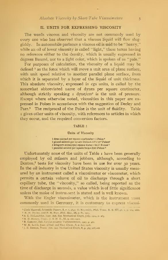
I. INTRODUCTION
In the determination of viscosity for technical purposes the
Engler and the Saybolt Universal viscosimeters are the ones mostcommonly used in the United States. With the former it is cus-
tomary to express results in " Engler degrees" obtained by divid-
ing the time of discharge for the liquid being tested by the timefor water at 20 C (68° F). With the latter instrument results
are expressed as the time of discharge, in seconds, of the liquid
being tested. There is, however, a growing demand for the ex-
pression of results in absolute or cgs units, but unfortunately the
outlet tubes of these instruments are so short that there is con-
siderable doubt as to the applicability of the formula showing the
relation between absolute viscosity and time of discharge, whichmay be used in determining absolute viscosity by means of a long
capillary tube.
Before this formula can be used it is necessary to decide uponthe coefficient of the kinetic-energy correction and the correction
to the measured length of tube, which is necessary to allow for
other end effects. A formula must be selected for finding the
average head and means found for determining under what con-
ditions the formula is applicable; that is, within what limits of
velocity there will be viscous flow as distinct from hydraulic or
turbulent flow.
These subjects have been investigated both in the literature and
by original experiments and the sources of error in viscosity deter-
minations are considered at length. Tentative formulas are given
for the determination of absolute viscosity from the time of flow
with normal volumes put in and discharged, while diagrams are
given which may be used to estimate the viscosity when abnormal
volumes are used.
A method is given by which each operator of a viscosimeter
may obtain the relation between viscosity and time of discharge
for his own instrument, without use of the tube dimensions, which
are difficult to determine with sufficient accuracy; and tables of
viscosities of the necessary calibrating liquids are given in an
appendix. This method is especially necessary because the Say-
bolt Universal viscosimeter has never been standardized as to the
dimensions of its parts and their allowable tolerances, so that all
data in regard to it must be regarded as merely approximate.
Absolute Viscosity by Short-Tube Viscosimeters 5
II. UNITS FOR EXPRESSING VISCOSITY
The words viscous and viscosity are not commonly used by
every one who has observed that a viscous liquid will flow slug-
gishly. In automobile parlance a viscous oil is said to be "heavy,"
while an oil of lower viscosity is called "light," these terms having
no reference either to the density, which is usually expressed in
degrees Baume, nor to a light color, which is spoken of as "pale."
For purposes of calculation, the viscosity of a liquid may be
denned * as the force which will move a unit area of plane surface,
with unit speed relative to another parallel plane surface, from
which it is separated by a layer of the liquid of unit thickness.
This absolute viscosity, expressed in cgs units, is called by the
somewhat abbreviated name of dynes per square centimeter,
although strictly speaking 1 dyne/cm2is the unit of pressure.
Except where otherwise noted, viscosities in this paper are ex-
pressed in Poises in accordance with the suggestion of Deeley and
Parr. 2 The reciprocal of the Poise is the unit of fluidity. Table
1 gives other units of viscosity, with references to articles in which
they occur, and the required conversion factors.
TABLE 1
Units of Viscosity
1 dyne-second per square centimeter= 1 Poise 8
1 pound-minute per square inch= 4.137X 10 6 Poises*
1 kilogram-second per square meter= 98.07 Poises 6
1 poundal-second per square incn=2143 Poises 6
Unfortunately none of the units of Table i have been generally
employed by oil refiners and jobbers, although, according to
Denton, 7 tests for viscosity have been in use for over 30 years.
In the oil industry in the United States viscosity is usually meas-
ured by an instrument called a viscosimeter or viscometer, which
permits a certain volume of oil to discharge through a short
capillary tube, the "viscosity," so called, being reported as the
time of discharge in seconds, a value which is of little significance
unless the make of instrument is stated and is well known.With the Engler viscosimeter, which is the instrument most
commonly used in Germany, it is customary to express viscosi-
1 Clerk Maxwell, Scientific Papers, 2, p. 7, 1890: O. Reynolds, Phil. Trans. R. S. 177, pt. 1, p. 164, 1886.
2 R. M. Deeley. and P. H. Parr, Phil. Mag., 26, p. 87, 1913.
» A. C. McLaughlin, Jour. Am. Soc. Mechanical Engrs, July, 1914, p. 263.
* M. D. Hersey, Trans. A. S. M. E., 37, p. 167; 1915.
5 R. Camerer, Zeit. f Lir das gesamte Turbinenwesen, 1907, p. 461.
6 W. K. Lewis, Jour, of Ind. and Eng. Chem., 8, p. 627; 1916.
7J. E. Denton, Trans. Am. Soc. Mechanical Engrs, 9, p. 369; 1887-88.

6 Technologic Papers of the Bureau of Standards
ties in "Engler degrees," which is a purely arbitrary scale found
by dividing the time of discharge for the liquid being tested bythe time for distilled water at a temperature of 20 C (68° F).
III. FORMULA FOR DETERMINING VISCOSITY BYCAPILLARY-TUBE EXPERIMENTS
Poiseuille 8 undertook about 1838 an experimental investi-
gation of the flow in capillary tubes, and found that the discharge
increased as the first power of the pressure and as the fourth
power of the diameter of the tube and was inversely proportional
to its length. Subsequent investigators have confirmed this
result mathematically, and found that if ju represents the viscosity
fii.l£*(I)
t 128M/U
where Q = discharge in time t.
P = difference in pressure between the two ends of the tube
I = length of tube, of diameter d
It had been noted by Poiseuille that although his results were
usually concordant and, as is now known, agreed with equation
(1) they did not agree with this law when the velocity was very
high in his shortest tubes. Equation (1) would give fairly accu-
rate results for a very long tube, but requires correction for use
with most viscosimeters, since part of the pressure is in reality
expended in setting the liquid in motion and not in overcoming
viscous resistance. Hence a " kinetic-energy correction " must be
deducted from P in order to get the effective pressure, and values
of the viscosity, calculated from Poiseuille's formula, equation (1),
will always be too high.
As pointed out by Couette,9 the measured length of tube /
requires correction to allow for "end effects" other than the loss
of head causing acceleration. Making the necessary correction to
P, as well as to /, equation (1) may be written 10
M icg d4
7 128 Q (Z+A)(h-™^) (2)
8J. Iv. M. Poiseuille, Memoires de l'institut, savants ctrangers, 9, pp. 433-544; 1846.
9 M. Couette, Annales de chimie et de physique, 21, p. 469; 1890.
10 This is equivalenc to equation (la) of E. C. Bingham, Scientific Paper No. 278, Bureau of Standards,
p. 319; 1916.
Absolute Viscosity by Short-Tube Viscosimeters 7
where p = viscosity in Poises
d = diameter of tube, in centimeters
(7+X) = effective length of tube, in centimeters
Q = discharge (cubic centimeters) in time t, seconds
v = mean velocity in the tube, in centimeters per second
m = coefficient of the kinetic energy correction
g = acceleration of gravity =981 cm/sec. 2
h = head in centimeters of liquid of density 7 in grams per
cubic centimeter
In deriving equation (2) from equation (1) the pressure, P, is
expressed by g y h since in short-tube viscosimeters, such as are
used for technical purposes, the pressure is usually produced by
a head of the viscous liquid. The expression - is known as the
kinematic viscosity, and it is evident that in order to determine
true viscosity with an efflux viscosimeter, densities must be
determined by an auxiliary instrument. In most viscosimeters
the discharge takes place under a decreasing head, and the deter-
mination of the average head is not always a simple matter.
Proper values for m and X must also be determined, from theory
or experiment, before equation (2) can be used. It is usual to
assume that X is proportional to the radius of the tube, so that
2 X = nd (3)
where wis a constant to be determined.
IV. REYNOLDS'S FORMULA FOR CRITICAL VELOCITY
It has been found that after a certain velocity of flow is exceeded
and turbulence appears, equation (2) will no longer apply, and
after an intermediate regime of rather unstable conditions, a fur-
ther increase of velocity will produce a second stable regime of
turbulent or hydraulic flow. If the viscosity of water at o° C(32 ° F) is taken as 0.017921 , it may be calculated from data given
by Reynolds " that when turbulence begins " Reynolds's criterion"
will have the valuevdy .
x= 2010. (4)
This value, which is usually taken as 2000, is only an approxima-
tion, and applies only to pipes of considerable length, as used byReynolds. This investigation has shown that it does not at all
hold for short tubes.
" O. Reynolds, Phil. Trans. R. S., 174, pt. 3, p. 948; 188.3.
8 Technologic Papers of the Bureau of Standards
According to Flowers 12 the principal types ot technical viscosim-
eters were devised, shortly after the publication of Reynolds's
work, so that with the standard, water, the velocity would fall
just below the critical value, as determined by equation (4). Hesays, further, that Reynolds's results have been "taken errone-
ously" to mean that below this velocity no eddies would occur,
even with short tubes. Hayes and I^ewis 13 also find that the
critical velocity is exceeded with most of the viscosimeters in com-
mon use.
V. METHODS OF FINDING THE RELATION BETWEENKINEMATIC VISCOSITY AND TIME OF DISCHARGE
1. ARCHBUTT AND DEELEY'S EQUATION
For any given viscosimeter, when a constant volume, Q, is
allowed to run out, equation (2) becomes
*-**-!(5 )7 tvo/
in which A and B will be constants if X, m, and h are constant.
Omitting the separate term for the kinetic-energy correction, Arch-
butt and Deeley 14 write
H = kyt (6)
where k, the ratio of kinematic viscosity to time of discharge, is a
variable to be found by experiment. If the kinetic-energy cor-
rection is negligible, as with very viscous oils, k is a constant, and
it follows from equation (6) that if two liquids with viscosities of
/*! and ju2 have times of discharge, tx and t2 , respectively, then
equation (6) becomes simply the Ostwald formula
It will be noted that equation (7) can not be derived from equa-
tion (5) except on the assumption that the kinetic-energy correc-
tion is negligible, and very serious errors are frequently caused bythe use of equation (7) when this assumption is not warranted.
Archbutt and Deeley give tables of viscosities and densities of
solutions of glycerol and water for use in finding the variable, k,
for any given viscosimeter. Having obtained experimentally the
times of discharge for several solutions, for the instrument in ques-
12 A. E. Flowers, Proc. A. S. T. M., 14, pt. 2, pp. 577, 582; 1914.
iJ H. C. Hayes and G. W. Lewis, Jour. A. S. M. E., 38, p. 629; 1916.
14 L. Archbutt and R. M. Deeley, Lubrication and Lubricants, p. 180; 1912.

Absolute Viscosity by Short-Tube Viscosimeters 9
tion, values of k may be calculated from equation (6). Interpo-
lated values of k may then be used to find the viscosities of other
liquids.
2. HIGGINS'S GRAPHICAL METHOD
Higgins 15 gives a method for finding values for the constants
in equation (5) . By combining equations (5 and 6)
Then if values of k are plotted as oidinates against values of -
as abscissas, the points lie on a straight line. The intercept of this
line on the ordinate where 1/t2 = o gives the value of A , and the
slope of the line gives the value of Z?.16
Speaking of the Redwood viscosimeter, Higgins says: "Thevalue of A is, however, obtained more accurately from the slope
of the curve connecting p/y and t, for values of t greater than 200.
For these values B/t is negligibly small compared with At." In
this case the kinematic viscosity is proportional to the time, as in
equation (7). It is evident that the value of 200 seconds applies
only to the Redwood viscosimeter, and that for any other instru-
ment a decision would have to be made as to the appropriate
value.
3. UBBELOHDE'S EQUATION
Ubbelohde's tables ir are computed from the formulas
7 A rvro F 3-513 4-072 t 3-513 *w (9)
n = 0.01797 Zy (10)
where E is a measure of viscosity known as "Engler degrees,"
which is obtained by dividing the time of discharge, t, for 200
cubic centimeters of the liquid to be tested, by the time, tw , for
distilled water at 20 C (68° F) . tw , expressed in seconds, is knownas the water rate. The constant 0.01797 *s taken as the viscosity
of water at o° C (32 F).
Concerning the "empirical" formula, equation (9), Ubbelohde
says: "The formula was derived and confirmed by comparative
15 W. F. Higgins, Collected Researches, The National Physical Laboratory, 11, p. 12; 1914.
18 For methods of determining the equation of a curve which will fit a faeries of experimentally determined
points, seeC. T. Brady, jr., Engineering News, 63, p. 163, 1913;"^". H. Herschel, Bull. Soc. for the Promotionof Engineering Education, 5, p. 33, 1915; J. B. Kommers, The Wisconsin Engineer, 20, p. 106; 1915.
17 L. Ubbelohde, Tabellen zum Englerschen Viskosimeter, pp. 9, 27; 1907.
1392°—17 2
io Technologic Papers of the Bureau of Standards
tests with a capillary apparatus which gave specific viscosity
directly," specific viscosity being defined as Zy = z. No detailed
account of these tests appears to have been published. 18 Hayes 19
says that Ubbelohde's formula ''is only claimed to be approxi-
mate," but it has been generally accepted as at least the best
formula available for converting Engler time into Poises. 20 Ubbe-lohde 21 himself admits elsewhere that his equation does not applyto liquids of greater fluidity than water, while maintaining that
it was "derived theoretically but has been experimentally con-
firmed." Speaking of liquids with a viscosity, expressed in
Engler degrees, of i or less, he says:
For such thinly fluid substances almost identical Engler values are obtained for
liquids which in reality have very different viscosities, * * * viscosities can not
be deduced from the Engler values for such thin liquids. (See my article Die Zahig-
keit des Leucht-petroleums und ein Apparat zu ihrer Bestimmung, Zeitschrift " Petro-
leum," 4, No. 15.)
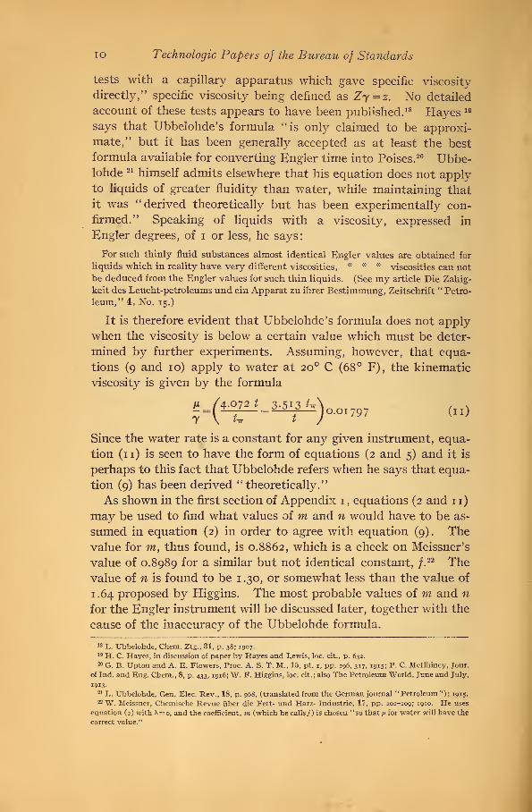
It is therefore evident that Ubbelohde's formula does not apply
when the viscosity is below a certain value which must be deter-
mined by further experiments. Assuming, however, that equa-
tions (9 and 10) apply to water at 20 C (68° F), the kinematic
viscosity is given by the formula
u /4.072 t 3. si^ tw\ , vy(u iA7^)°-OI 797 (11)
Since the water rate is a constant for any given instrument, equa-
tion (11) is seen to have the form of equations (2 and 5) and it is
perhaps to this fact that Ubbelohde refers when he says that equa-
tion (9) has been derived "theoretically."
As shown in the first section of Appendix 1 , equations (2 and 11)
may be used to find what values of m and n would have to be as-
sumed in equation (2) in order to agree with equation (9) . Thevalue for m, thus found, is 0.8862, which is a check on Meissner's
value of 0.8989 for a similar but not identical constant, y.22 The
value of n is found to be 1 .30, or somewhat less than the value of
1.64 proposed by Higgins. The most probable values of m and n
for the Engler instrument will be discussed later, together with the
cause of the inaccuracy of the Ubbelohde formula.
18 L. Ubbelohde, Chem. Ztg., 81, p. 38; 1907-
19 H. C. Hayes, in discussion of paper by Hayes and Lewis, loc. cit., p. 632.
20 G. B. Upton and A. E. Flowers, Proc. A. S. T. M., 15, pt. 1, pp. 296, 317, 1915; P. C. Mcllhiney, Jour,
of Ind. and Eng. Chem., 8, p. 433, 1916; W. F. Higgins, loc. cit. ; also The Petroleum World, June and July,
1913-
21 I,. Ubbelohde, Gen. Elec. Rev., 18, p. 968, (translated from the German journal "Petroleum"); 1915.
22 W. Meissner, Chemische Revue iiber die Fett- und Harz- Industrie, VI, pp. 202-209; 1910. He uses
equation (2) with X=o, and the coefficient, m (which he calls/) is chosen "so that n for water will have the
correct value."

Absolute Viscosity by Short-Tube Viscosimeters ii
4. MEISSNER'S COMPARISON OF THE ENGLER AND THE SAYBOLTUNIVERSAL VISCOSIMETERS
If km and ks are values of the variable k of equation (6) for the
Engler and Saybolt 23 viscosimeters, respectively, then, when the
kinetic-energy correction is negligible
= &e tn = ks ts (12)
from which2e ka
, Jyr— = -j— = constant =Kts &E
(13)
Meissner 24 gives the time of discharge for the Saybolt and Engler
instruments, for liquids of five different viscosities, as in Table 2.
TABLE 2
Relative Times of Discharge for the Engler and Saybolt Viscosimeters, According to
Meissner
Liquid
Water at 20° C (68° F)
Rape oil at 50° C (122° F)_...
Machine oil at 50° C (122° F)
Rape oil at 20° C (68° F)
Machine oil at 20° C (68° F).
Reducedtime,
Engler,average of
two in-
struments
Sec.
50.94
233.6
357.0
730.8
2491.0
Time,Saybolt
Sec.
28.55
169.1
258.6
515.6
1759.
1.784
1.381
1.381
1.417
1.416
It will be seen from the last column, which was not given byMeissner, that the minimum value of K does not occur for the
maximum viscosity as it would according to Meissner's formulas
for the two instruments. It is therefore necessary to attribute
the discrepancy to experimental error, to surface tension or to
some other cause not taken into account in deriving these equa-
tions. If it is assumed that the kinetic-energy correction is neg-
ligible in all Meissner's tests with oil, then, excluding the test with
water, the average value of K is 1.399. As shown in the second
section of Appendix 1 , Meissner's method of averaging leads to a
value of K = 1.391, and with the help of this value, and Meissner's
23 When the Saybolt viscosimeter is referred to in this paper, the Saybolt Universal is meant, and this
should not be confused either with the earlier forms of Saybolt instrument (see W. M. Davis, Friction andLubrication, p. 44, 1904), nor with the latest form with a cover (U. S. Patent No. 1132621, of Mar. 23, 1915).
Much that is said concerning the Saybolt instruments which have been used in this investigation may not
apply to the form with a cover.
24 W. Meissner, loc. cit., 19, p. 30; 1912.
1
2
Technologic Papers of the Bureau of Standards
•equation for the Engler instrument, it may be found that for the
Saybolt instrument n = i. 21 and m = o.88. These are not essen-
tially different from the values previously found from Ubbelohde's
equation for the Engler instrument. It will be noted that in
spite of Meissner's disregard of n in his equation for the Engler
instrument his own equations are equivalent to taking n into
account for the Saybolt instrument.
VI. GRAPHICAL METHODS FOR STUDYING THE LAWS OFFLOW THROUGH CAPILLARY TUBES
1. GRUNEISEN'S DIAGRAM
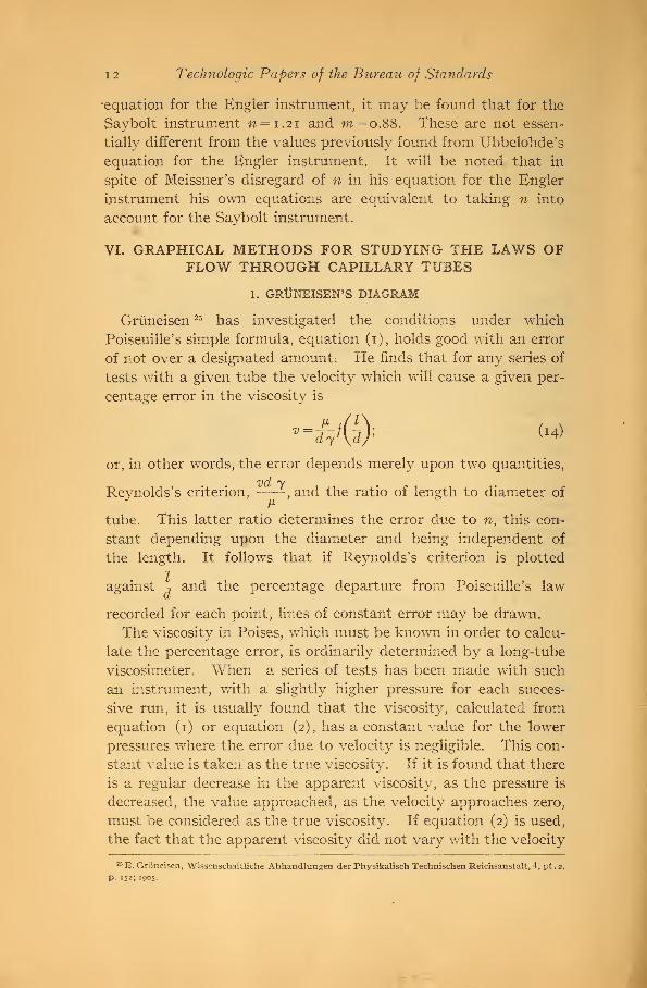
Griineisen 25 has investigated the conditions under which
Poiseuille's simple formula, equation (1), holds good with an error
of not over a designated amount. He finds that for any series of
tests with a given tube the velocity which will cause a given per-
centage error in the viscosity is
JLdy<a> N
or, in other words, the error depends merely upon two quantities,
vd yReynolds's criterion, —— , and the ratio of length to diameter of
tube. This latter ratio determines the error due to n, this con-
stant depending upon the diameter and being independent of
the length. It follows that if Reynolds's criterion is plotted
against , and the percentage departure from Poiseuille's law
recorded for each point, lines of constant error may be drawn.
The viscosity in Poises, which must be known in order to calcu-
late the percentage error, is ordinarily determined by a long-tube
viscosiineter. When a series of tests has been made with such
an instrument, with a slightly higher pressure for each succes-
sive run, it is usually found that the viscosity, calculated from
equation (1) or equation (2), has a constant value for the lower
pressures where the error due to velocity is negligible. This con-
stant value is taken as the true viscosity. If it is found that there
is a regular decrease in the apparent viscosity, as the pressure is
decreased, the value approached, as the velocity approaches zero,
must be considered as the true viscosity. If equation (2) is used,
the fact that the apparent viscosity did not vary with the velocity
25 E. Griineisen, Wissenschaftliche Abhandlungen der Physikalisch Technischen Reichsanstalt, 4, pt. 2,
p. 152; 1905.

Absolute Viscosity by Short-Tube Viscosimeters 13
would, if the kinetic-energy correction were appreciable, be an
indication that the assumed value of m was sufficiently accurate.
The assumption in regard to X could not be checked without the
use of a second tube.
The apparent viscosity, as calculated from equation (1), will be
called /x1 to distinguish it from the true viscosity n. Then the
percentage error in the viscosity as calculated by equation (1)
will be
( — — 1J100 = percentage error (15)
2. A NEW DIAGRAM *s
In Fig. 1 Reynolds's criterion, —:— , has been plotted against
the percentage error in the Poiseuille formula, ( 1J100. An
advantage of this form of diagram is that, without the use of
logarithms, straight lines are obtained, from which values of mand n may be derived. It has the advantage, as compared with
Higgins's method, of retaining Reynolds's criterion as a warning
when the velocity is too high for equation (2) to apply. If a line
on Fig. 1 represents a series of tests on a single tube, with veloci-
ties all below the critical value so that equation (2) will apply,
then, as shown in the third section of Appendix 1, the tangent of
the angle between this line and the axis of abscissas will have
the value
tanfl=32/
, (16)100 met v y
and the value of the percentage error, at the point where the
calibration curve, extended, intersects the axis of abscissas, is
equal to
/7+X \ 100X so nd . .
(-T—ijl0o=-r
-=-r-
( I7 )
If, as maintained by Couette, X always has a plus value, all cali-
bration curves must intersect the axis of abscissas to the right of
the origin. It follows from equation (16) that a straight line on
Fig. 1 indicates that m does not vary with the velocity.
VII. APPLICATIONS OF THE NEW DIAGRAM
Fig. 1 shows points calculated from tests of Poiseuille and Holde
with water of given temperatures. 26* As shown in the fourth section
24 For the first published mention of this diagram, see Jour, of the Wash. Acad. Sciences, 6, p. 155; 1916.
26a See Mitteilungen aus den Koniglichen technischen Versuchsanstalten, Erganzungsheft 1, p. 9; 1895.

14 Technologic Papers of the Bureau of Standards
fQQ ZOO 300 400 500 600 700 BOO 300 /OOP HOP
Vercenlaqe error in Toiseailie formula.
Fig. i.—A new diagram for studying the laws offlow through capillary tubes
Most of Poiseuille's tests agree very closely with his formula. The excessive errors shown in Figs, i
and 3 are due to the selection of tests of high velocity, to which, as recognized by Poiseuille, the formula
does not apply.
Absolute Viscosity by Short-Tube Viscosimeters 15
of Appendix 1 , the work of calculation may be simplified by using
constants which depend on the dimensions of the tube, while true
viscosities and densities may be taken from Appendix 2. Poi-
seuille made his experiments with glass tubes of various lengths,
while Holde used Engler instruments with tubes of abnormal
dimensions, so that the lengths varied from 6.8 to 7.1 diameters,
the normal value being '
Q =7.02. Archbutt and Deeley's cali-& 0.285' J
bration of the Redwood viscosimeter was made with glycerol solu-
tions, for which they give the viscosities and densities. The lines
for the Engler and the Saybolt Universal viscosimeters are calcu-
lated from equation (9) and equation (36) of the second section of
Appendix 1 by assuming values of the time of discharge. It will
be noted that the upper end of the line for the Engler viscosimeter
agrees fairly well with the average of the points calculated from
Holde 's tests.
Archbutt and Deeley's tests, when plotted on Fig. 1, show a
curved line, but this curve is based on too few points to be con-
clusive. Poiseuille's shortest tube, A-7, had a ratio of length to
1 (?)
diameter of— J- = 7.04, and tests on this tube also give a curved0.1417 ' ™ &
line. Other tests of Poiseuille, with longer tubes, give lines which
are straight at their lower ends. No definite conclusion can be
drawn from Fig. 1 as to whether the curvature of the lines for
Poiseuille's tube, A-7, and for the Redwood viscosimeter, is due
to experimental error or is correct. While the question mark,
which is Poiseuille's, shows that the length of the tube, A-7, is
probably in error, only the position of the line on the diagram,
but not its shape, would thereby be affected.
One object of this investigation was to determine whether tests
on short tubes, such as are used in technical viscosimeters, could
be correctly represented by straight lines on a diagram similar to
Fig. 1, or, in other words, whether m and n of equation (2) are
constants.
VIII. CONDITIONS AFFECTING THE ACCURACY OF MEAS-UREMENTS WITH TECHNICAL VISCOSIMETERS
In using the Engler and the Saybolt Universal viscosimeters,
the following sources of error have been noted
:
1. STARTING THE FLOW
In the Saybolt instrument the flow is started by removing acork from the bottom of a tube which is concentric with and
1
6
Technologic Papers of the Bureau of Standards
extends below the lower end of the capillary tube. When the
cork is inserted and the oil container is filled, the oil is prevented
from flowing out by the compressed air inside the larger tube
between the cork and the lower end of the capillary tube. If the
cork leaks, as may easily happen, especially with very mobile
liquids such as gasoline or hot water, this space will become filled
and its contents will fall into the flask or upon the table as soon as
the cork is removed. It should be noted that this liquid has not
passed through the capillary tube during the measured time andthat consequently it is a source of error if any of it falls into the
flask. The flask usually supplied with the Saybolt instrument
has a mouth \% inches in diameter, and the use of a smaller
diameter (for example, yi inch, as in the tests here described)
would tend to reduce this error.
The cork should not be inserted while the liquid is flowing, as in
this case also some liquid is trapped in the space above the cork.
To wait for all the liquid to flow out, in case of a retest, causes
considerable delay if the liquid is very viscous, but this difficulty
may be avoided by using a glass rod to cover the upper end of the
capillary tube; afterwards, however, inserting the cork, removing
the rod, and using the cork to start the flow.
With some oils considerable trouble was experienced by the
deflection of the jet from its vertical direction, so that it touched
the outer tube, into which the cork is inserted, and left the instru-
ment more nearly horizontally than vertically. Apparently this
was due to a drop of a rather gummy oil forming a connection
between the jet and the walls of the outer tube.
2. STOPPAGE OF THE OUTLET TUBE
Since the diameter of the capillary tube of the Saybolt instru-
ment is less than that of the Engler it might be expected that more
difficulty would be experienced with stoppage. If the time of
discharge for the Saybolt instrument were too large, due to stop-
page, and the Engler outlet tube were clear, the ratio of time,
Engler, to time, Saybolt, would be too low, and there is reason to
believe that this occurred not infrequently. While the plunger
furnished with the Saybolt instrument is convenient for blowing
out the capillary tube, it hardly compensates for the much greater
inaccessibility of the tube as compared with that of the Engler
instrument. It was always easy to see that the Engler tube wasclear or to get at it to clean it. Advocates of the Saybolt instru-
ment suggest the apprehension that splinters from the wooden

Absolute Viscosity by Short-Tube Viscosimeters 17
skewer used to stop the upper end of the Engler capillary tube
might become lodged in the tube, but no difficulty was experienced
on this account and I believe the fear to be groundless. It is
possible that with years of use the tube might become enlarged
near the upper end from wear, but this could be detected by the
change in the water rate. On the other hand, the anxiety that
the Saybolt outlet tube might be stopped was always present,
although relieved by swabbing it out with a thread wound around
a broom straw, and noting that the time of discharge was not
changed. To avoid danger from lint, paper was always used to
clean the oil container of the Engler instrument.
3. ERROR IN FILLING
With the Sa}^bolt instrument the oil container is filled until it
overflows into a gallery and then the gallery is emptied by using a
pipette. With the Engler instrument the oil level is adjusted until
three sharp points, equally spaced around a circle, just pierce the
surface of the liquid. These gage points are similar to what is
known to hydraulic engineers as a "hook gage" which is used to
measure the height of water above a weir where extreme accuracy
is desired. From experience with both methods, if care is taken,
I believe more accurate filling of the oil container may be obtained
with the Engler instrument, but with careless work the error would
be greater than with the Saybolt instrument unless, indeed, the
blunder was made of forgetting to empty the gallery or not remov-
ing enough of the liquid with the pipette. Very viscous oils cling
to the sides of the gallery and may flow down and fill the gallery
too full after it has been partly emptied. On the other hand,
with the Engler instrument a very viscous oil will adhere to the
skewer, thus increasing the amount by which the liquid surface is
lowered when the skewer is withdrawn. An electric lamp con-
nected to an extension cord was found convenient to get a better
light on the gage points when filling the Engler instrument.
4. ERROR DUE TO BUBBLES IN THE MEASURING FLASK
The direction is usually given to let the jet fall into the flask
without touching the neck, because otherwise there is an error
due to the time required for the oil to flow from the point where
it str kes the neck to the graduation. With many oils, however,
this method of procedure gives rise to bubbles, which may cause a
greater error, due to uncertainty as to the instant when the menis-
cus reaches the graduation. All things considered, I believe it is
1392°—17 3

1
8
Technologic Papers of the Bureau of Standards
preferable to avoid the bubbles by letting the jet strike the neck
when necessary, which is fortunately not apt to be the case with a
very viscous oil. Any error that may be caused by the flow of
oil down the neck may be decreased by the selection of flasks
which have the graduation near the top of the neck.
5. CONTROL OF TEMPERATURE
With the Engler and the older forms of Saybolt instruments
the constant-temperature bath is heated only by a Bunsen burner.
By fastening the Engler burner to a leg of the tripod with a piece
of wire, so that it could be slipped up and down but could not
swing and overheat the capillary tube or break the flask, the Engler
burner was much more convenient to use than the Saybolt, as the
temperature of the bath could be adjusted by the position of the
burner as well as the size of the flame. On this account, andbecause the burner could not be considered an essential feature of
a viscosimeter, the Saybolt burner was discarded entirely and the
Saybolt bath was heated by placing it on the Engler tripod.
It is evident that if the bath was heated no higher than the
temperature at which the oil was to be tested, the time required
for the oil to heat up would be excessive, and that from practical
considerations it is necessary to have the bath at a slightly higher
temperature. The oil being tested will therefore increase in tem-
perature during the run, and the best result will be obtained if the
average temperature of the oil during the run is the temperature
desired. With the Engler instrument the thermometer may be
left in place throughout the run, and the temperature at the end
is as easily noted as at the beginning, though perhaps not so accu-
rately. But where the thermometer has to be withdrawn whenthe run is started, the temperature at the end of the run can only
be estimated from the rate of rise of temperature before the ther-
mometer was withdrawn. To get the average temperature during
the run allowance must be made for the time lost in withdrawing
the thermometer and in emptying the gallery before the run is
begun.
It was found that there was a tendency for the temperature of
the oil to increase when tests were made at room temperature,
and this was doubtless due to the heat of the hand applied to the
flask. It was therefore found necessary either to work at a tem-
perature sufficiently above the room temperature so that moreheat was lost by radiation than was gained in this manner or to
Absolute Viscosity by Short-Tube Viscosimeters 19
avoid surplus heat by keeping the temperature of the bath below
that at which tests were made.
Since viscosity is not proportional to temperature, there is an
inaccuracy in averaging temperatures. Two methods have been
found convenient in keeping the temperature changes as small as
possible. When the oil has reached the desired temperature the
bath may be cooled to the temperature of the oil by siphoning off
part of the water and refilling the bath with cold water. If
other means of heating are available, it is more convenient to keep
the bath as near as possible to the temperature desired and heat
the oil outside the viscosimeter. It is necessary to allow for a
slight fall in temperature when the oil is poured into the visco-
simeter.
6. METHOD OF VISCOSIMETER COMPARISON WITHOUT TEMPERATURECONTROL
With very mobile liquids the greatest error was in starting and
stopping the watch, but it was assumed that this was practically
eliminated by taking an average of 10 runs. This rule wasadhered to for all tests except those with mixtures of kerosene andspindle oil used in obtaining Figs. 9 and 10. It was found that with
the most careful work the difference between the maximum andminimum values of the time of discharge was rarely less than one
second for each minute of the average time, which would bring
extreme values slightly less than 1 per cent from the average.
With the more viscous oils the greatest error was due to diffi-
culty of temperature control, a difficulty which became the moreserious with the more viscous oils, which changed in viscosity the
more rapidly with the temperature. Therefore I used a methodwhich would give correct results, provided that the temperature
was either constant or varied uniformly. Three viscosimeters,
two Saybolt and one Kngler, were placed side by side on the bench
and the baths emptied so that the instruments were practically
all in one air bath at room temperature. Then tests were madein the order Saybolt No. 580, Engler, Saybolt No. 727; Saybolt
No. 727, Engler, Saybolt No. 580, which gave two tests for each
instrument, and the average temperature for each instrument
would be the same, provided that the length of time lost and spent
in operations was always the same, and the rate of change of
temperature of the room was uniform.

20 Technologic Papers of the Bureau of Standards
IX. THE RELATION BETWEEN KINEMATIC VISCOSITY ANDTIME OF DISCHARGE FOR THE ENGLER AND THE SAY-BOLT UNIVERSAL VISCOSIMETERS
1. SUITABLE LIQUIDS
The number of easily obtainable liquids of which the viscosity
is accurately known is very limited . Rayleigh 27 says: "Theviscosity of water may be diminished (to about one-fourth) byheating it, or increased by admixture of alcohol." Bingham and
Jackson 28 recommend water, and both alcohol and sucrose solu-
tions. Redwood 29 proposed, and later adopted rapeseed oil as
a standard, though, as pointed out by Meissner, there is consider-
able doubt as to whether even the best refined oil will not suffer
considerable change in viscosity with time. Archbutt, in dis-
cussing Redwood's proposal, said that in a number of tests with
a certain viscosimeter he found that "the viscosity varied from
ioo to 109, whilst one or two samples went as high as 127 on the
same scale. These samples were all genuine by chemical tests,
and he supposed the oil which gave the high results to be summerrape, which is said to be more viscous than winter rape." Pre-
sumably any other vegetable oil would be of uncertain viscosity,
both on account of variations in viscosity between different
samples when fresh and on account of changes in viscosity of any
one oil with time.
Long-tube viscosimeters are usually completely inclosed so
that there can be no loss of the liquid being tested by evaporation.
With instruments which discharge into the air evaporation is a
serious source of error at high temperatures if solutions or mix-
tures are used which change in viscosity upon the loss of the morevolatile constituent. Alcohol and sucrose solutions are both open
to this objection, but it is to be noted that the viscosity of an
alcohol solution of approximately 50 per cent alcohol does not
change very rapidly with a change in concentration.
There is a great need of an easily obtainable liquid having a
viscosity greater than 0.024 Poise, which is the value for a 50 per
cent alcohol and water solution at a temperature of 25 ° C (77 F).
Of the 72 chemical compounds investigated by Thorpe andRodger 30 only 6 fatty alcohols have a viscosity greater than the
50 per cent solution of ethyl alcohol and water, the highest value
27 Lord Rayleigh, Report British Advisory Committee for Aeronautics, 1, p. 38; 1909-10.28 E. C. Bingham and R. F. Jackson, Scientific Paper, Bureau of Standards, No. 298; 1917.29 B. Redwood, Jour. Soc. for Chem. Industry, 5, p. 127: 1886.
*> T. E. Thorpe and J. W. Rodger, Phil. Trans. R. S., 185, pt. 2, p. 572: 1894.
Absolute Viscosity by Short-Tube Viscosimeters 21
recorded being 0.141 79 Poise for dimethyl ethyl carbinol at zero de-
grees C (32 ° F) . The highest viscosity measured by Bingham and
Jackson for a 60 per cent sugar solution at ii.6i°C (52.9°F) was
=1.102 Poise. For a calibrating liquid of greater vis-
cosity castor oil is sometimes used, for which Archbutt and
Deeley 31 give a viscosity of 2.729 Poises at ioo° F (37.8° C).
The highest viscosity given by them is 11. 156 Poises for ''extra
L. L." cylinder oil at the same temperature. MacMichael 32
suggests for a standard testing fluid "a high-grade neutral min-
eral oil of high viscosity, such as some of the medicinal oils nowon the market," the viscosity of this oil to be determined by the
long-capillary-tube method and the oil to be supplied by some'
' recognized authority.'
'
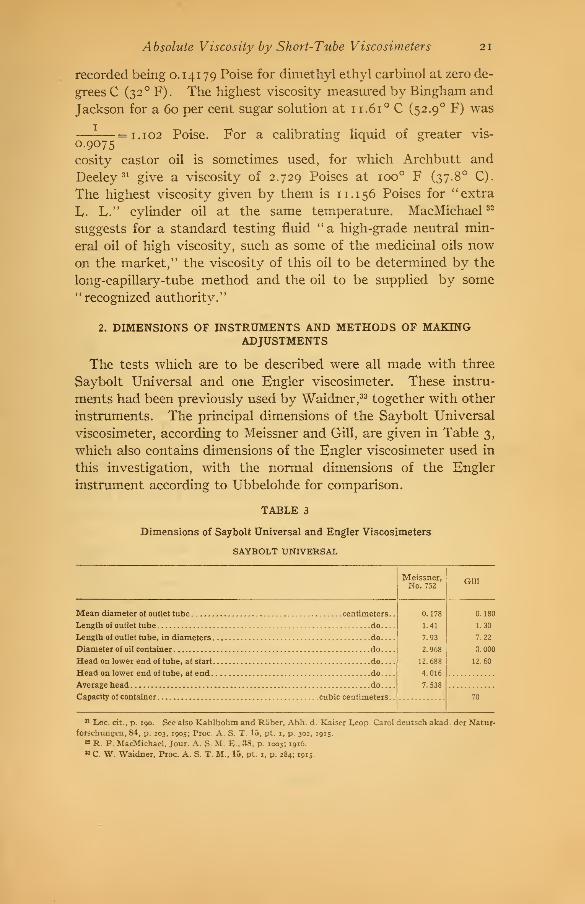
2. DIMENSIONS OF INSTRUMENTS AND METHODS OF MAKINGADJUSTMENTS
The tests which are to be described were all made with three
Saybolt Universal and one Engler viscosimeter. These instru-
ments had been previously used by Waidner,33 together with other
instruments. The principal dimensions of the Saybolt Universal
viscosimeter, according to Meissner and Gill, are given in Table 3,
which also contains dimensions of the Engler viscosimeter used in
this investigation, with the normal dimensions of the Engler
instrument according to Ubbelohde for comparison.
TABLE 3
Dimensions of Saybolt Universal and Engler Viscosimeters
SAYBOLT UNIVERSAL
Mean diameter of outlet tube centimeters.
.
Length of outlet tube do
Length of outlet tube, in diameters do
Diameter of oil container do
Head on lower end of tube, at start do
Head on lower end of tube, at end do
Average head do
Capacity of container cubic centimeters.
.
Meissner,No. 752
0.178
1.41
7.93
2.968
12.688
4.016
7.538
Gill
0.180
1.30
7.22
3.000
12.60
70
31 Loc. cit., p. 190. See also Kahlbohm and Raber, Abh. d. Kaiser Leop. Carol deutsch akad. der Natur-
forschungen, 84, p. 203, 1905; Proc. A. S. T. 15, pt. 1, p. 302, 1915.
B R. F. MacMichael, Jour. A. S. M. E., 38, p. 1003; 1916.
MC W. Waidner, Proc. A. S. T. M., 15, pt. 1, p. 284; 191s-
22 Technologic Papers of the Bureau of Standards
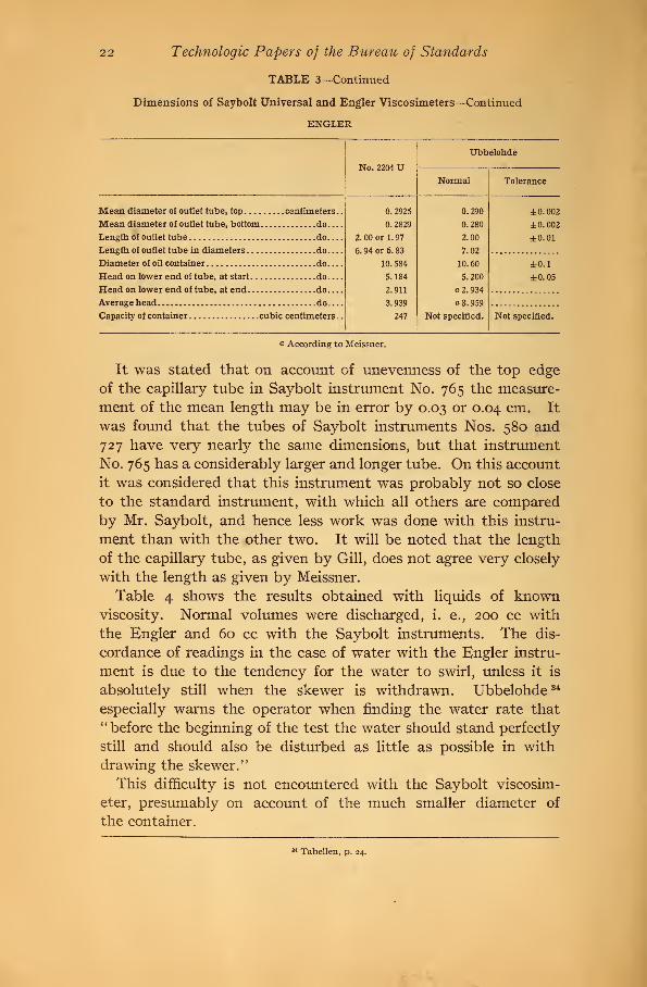
TABLE 3—Continued
Dimensions of Saybolt Universal and Engler Viscosimeters—Continued
ENGLER
No. 2204 UUbbelohde
Normal Tolerance
Mean diameter of outlet tube, top centimeters.
.
Mean diameter of outlet tube, bottom do
Length of outlet tube do
Length of outlet tube in diameters do
Diameter of oil container do
Head on lower end of tube, at start do
Head on lower end of tube, at end do
Average head do
—
Capacity of container cubic centimeters .
.
0. 2925
0. 2829
2. 00 or 1.97
6. 94 or 6. 83
10. 584
5.184
2.911
3.939
247
0.290
0.280
2.00
7.02
10.60
5.200
a 2. 934
a 3. 959
Not specified.
±0.002
±0.002
±0.01
±0.1
±0.05
Not specified.
a According to Meissner.
It was stated that on account of unevenness of the top edge
of the capillary tube in Saybolt instrument No. 765 the measure-
ment of the mean length may be in error by 0.03 or 0.04 cm. It
was found that the tubes of Saybolt instruments Nos. 580 and
727 have very nearly the same dimensions, but that instrument
No. 765 has a considerably larger and longer tube. On this account
it was considered that this instrument was probably not so close
to the standard instrument, with which all others are comparedby Mr. Saybolt, and hence less work was done with this instru-
ment than with the other two. It will be noted that the length
of the capillary tube, as given by Gill, does not agree very closely
with the length as given by Meissner.
Table 4 shows the results obtained with liquids of knownviscosity. Normal volumes were discharged, i. e., 200 cc with
the Engler and 60 cc with the Saybolt instruments. The dis-
cordance of readings in the case of water with the Engler instru-
ment is due to the tendency for the water to swirl, unless it is
absolutely still when the skewer is withdrawn. Ubbelohde 34
especially warns the operator when finding the water rate that" before the beginning of the test the water should stand perfectly
still and should also be disturbed as little as possible in with
drawing the skewer."
This difficulty is not encountered with the Saybolt viscosim-
eter, presumably on account of the much smaller diameter of
the container.
*4 Tabellen, p. 24.

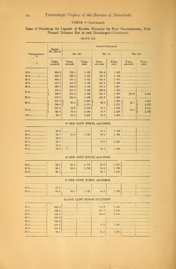
Absolute Viscosity by Short-Tube Viscosimeters
TABLE 4
23
Time of Discharge for Liquids of Known Viscosity for Four Viscosimeters, With
Normal Volumes Put in and Discharged
DISTILLED WATER
EnglerNo. 2204 U
Saybolt Universal
Temperature,°C
No. 580 No. 727 No. 765
Time,seconds
Time,seconds
Time,ratio
Time, Time,seconds ratio
Time,seconds
Time,ratio
3.0 32.1 32.0 '
4.0 56.3
5.0 31.6 :::::::::::::::::::::-:::i::::::::::::i:::::::::::-:i::::::::::::
5.5 55.5
6.0 31.2
30.7
i
1
7.0 30.8
8.0 :... 5,.
54.7
54.2
9.0
10.0 30.3
30.2
1.788i
'
11.0
12.0 30.1
30.013.0 53.6
53.4
53.3
53.0
J
52.4
1 53.1
[52.1
|52.9
I 52.6
J51.9
1 52.0
J51.2
1 51.3
51.3
511
30.0 1.782 1.790
14.0 a 29.7
a 29.4
29.2
}
1. 791
a 1.811
1.817
f 1.788
15.0 29.4
29.3
}29.4
I 28.8
1.818
1.811
j1. 788
} 1. 810
f 1. 805
|1.835
| 1. 822
16.0 28.6
1
1.850
f
17.0 \ 29.4 i 1
I
[28.9
I 1.810
f 1.801
I 1.830
| 1.818
f
1
\
18.0'
1
19.0 |"
20.0
20.5
} 28.5 1.801 28.3 1.813 28.0 1.832
21.0
23.0 28.6
24.0 27.5
24.5... 50.3
25.0 27.8
27.527.0
27.5 27.61
30.0 49.6
31.0 27.1
40.0 26.7
J26.2
1 26.8
25.6
i 25.7
50.0 47.7
46.2
1.822
1.788
1.801
1.801
26.4 1.810
26.1 l 1.830
25.4j
1.819
25.7 1-799
25.8 1.848
75.025.2 1.833
a At
24 Technologic Papers of the Bureau of Standards
TABLE 4—Continued
Time of Discharge for Liquids of Known Viscosity for Four Viscosimeters, WithNormal Volumes Put in and Discharged—Continued
OLIVE OIL
EnglerNo. 2204 U
Saybolt Universal
Temperature,°C
No. 580 No. 727 No. 765
Time,seconds
Time,seconds
Time,ratio
Time,seconds
Time,ratio
Time,seconds
Time,ratio
16.0 806.3
625.3
602.5
497.3
387.3
J278.
i 280.9
193.8
J133.
4
1 134.8
f 115.4
i 118.3
85.7
553.4
436.9
414.5
341.0
270.6
197.3
192.6
130.2
1 85.5
76.9
75.4
52.0
1.458
1.432
1.451
1.459
1.431
1.408
1.460
1.488
J1.560
1 1.575
1.500
1.569
1.651
534.6
434.8
416.0
353.4
277.6
200.0
192.7
132.2
}85.5
76.7
72.7
51.5
1.510
1.438
1.449
1.410
1.397
1.389
1.459
1.465
f 1.560
1 1.575
1.505
1.628
1.664
20.0
21.0
24.0
30.0
37.8193.0
50.0
1.455
65.6 } 85.7J
|67.4
J1.557
75.0
i 1.573
f 1.712
100.0
1 1.753
70 PER CENT ETHYL ALCOHOL
15.0 63.0
60.7
58.0
56.4
55.2
53.8
35.3
34.0
1.788
1.788
.
20.0 34.0 1.788
25.0*
30.0 31.0 1.821
35.0
40.0 29.2 1.838
10 PER CENT ETHYL ALCOHOL
10.0 58.5
56.5
55.5
33.0
31.6
1.773
1.792
32.8
31.6
30.4
1.782
1.790
1.822
1
15.0 1
20.0. .
I
i
50 PER CENT ETHYL ALCOHOL
10.0 62.3
69.320.0 40.2 1.725 40.2 1.725
60 PER CENT SUGAR SOLUTION
10.0 .. 632.4
266. S
214.4
174.5
156.0
144.1
118.3
93.6
443. 5
164.4
130.6
1.428
1.622
1.646
25.0
30.0
35.0
40.0
45.0 75.2 1.918
50.0
54.4 56.2
1
1.665

Absolute Viscosity by Short-Tube Viscosimeters 25
TABLE 4—ContinuedTime of Discharge for Liquids of Known Viscosity for Four Viscosimeters, With
Normal Volumes Put in and Discharged—Continued
ISOBUTYL ALCOHOL
EnglerNo. 2204 U
Saybolt Universal
Temperature,°C
No. 580 No. 727 No. 765
Time,seconds
Time, Time,seconds ratio
Time,seconds
Time,ratio
Time, Time,seconds ratio
20 41.2|
|
41.2
36.1
33.5
i
30
40 1
26. 32
22.10
8.70
17.90
11.34
9.06
I
1
20.0
70 cc put in and 60 cc discharged
60 cc put in and 50 cc discharged
60 cc put in and 20 cc discharged
50 cc put in and 40 cc discharged
45 cc put in and 25 cc discharged
45 cc put in and 20 cc discharged
It will be noted that the water rate for Saybolt No. 765 is a
little lower than for the other two Saybolt instruments, but that
there is substantial agreement in the time of discharge for olive
oil. Meissner has discussed mathematically the different methods
of making the final adjustments in viscosimeters, by changing the
head, as is done with the Redwood instrument; by reaming the
capillary tube, as is probably the method adopted with the
Engler; and by shortening the tube, as appears to be the methodemployed with the Saybolt instrument. He concludes that an
error in the head may be compensated by a change in diameter of
the tube, and vice versa, but that the length of the tube should be
accurately specified, with suitable tolerances. It follows from
this that if instruments are adjusted by shortening the tube, they
will agree at one viscosity but not at another, and this seems to be
confirmed by the tests of Table 4.
As no theoretical advantage has been claimed for the tapered
capillary tube of the Engler instrument, it seems probable that it
was designed with regard to ease of manufacture. This thought
was suggested by experience with steam-turbine nozzles, which
were brought to the exact diameter required by means of a tapered
reamer. This has the advantage over a cylindrical reamer that
the reamers do not have to be kept so nearly up to standard size,
since when one becomes smaller with wear it merely needs to be
thrust in farther. In making a capillary tube for a viscosimeter,
a tube of the right taper, but longer than necessary, might be1392°—17 4

26 Technologic Papers of the Bureau of Standards
prepared, and then this could be cut off at the right points so as
to give a tube of the required length and correct diameters at the
two ends.3. HIGGINS'S METHOD
The constants of equation (8) could be determined by finding the
time, t}for liquids of only two different viscosities. It is neces-
sary, however, to know what are the limits of the validity of
equation (8) and what liquids are suitable for purposes of test.
Over 500 tests, or 5000 runs, were made to answer these questions.
A graphical method, such as Higgins's, has the advantage over
a purely numerical method, in that tests which are evidently dis-
cordant may be rejected. As will be shown later, it has beenfound that for the Saybolt and Engler instruments, all tests should
be rejected for which Reynolds's criterion has a value in excess
of 800. In calculating this value it would be sufficiently accurate
to use the normal value of the tube diameter. For other types of
instrument the value of the criterion might vary, depending uponthe ratio of length to diameter of outlet tube, but additional
experiments are needed before the value of the criterion for the
critical velocity can be predicted from the dimensions of the tube.
Fig. 2, for the Engler instrument, has been obtained from data
of Table 4. If the usual practice is followed by using only tests
with water at 20 C (68° F) and with one or more liquids of fairly
high viscosity, the dotted line would be the result. It is evident,
however, that this line is incorrect because it does not agree with
tests with water at other temperatures or with alcohol and water
solutions.
4. TENTATIVE EQUATIONS FOR THE ENGLER AND THE SAYBOLT UNI-VERSAL VISCOSIMETERS
Figs. 3 and 4 have been calculated from data of Tables 3, 4, and
10. Two series of tests by Couette are also shown on Fig. 3. In
both figures Reynolds's criterion is plotted against the percentage
error in Poiseuille formula due to end effects, the necessary cal-
culations being made as for Fig. 1.
Fig. 3 shows a break in the curves for both viscosimeters at
points where the ordinate has a value of about 1000. Since the
ud'vvalue of Reynolds's criterion, —-, calculated from tests with water
at 20 C (68° F) , is found to be about 1 500 for the Saybolt and 1 750
for the Engler instrument, as shown on Fig. 1 , it follows that water
at that temperature is not a suitable liquid for testing purposes, as
also appeared from Fig. 2.

Absolute Viscosity by Short-Tube Viscosimeters 27
The dotted line in Fig. 3 for Ubbelohde's formula for the Engler
instrument, is taken from Fig. r. If equation (9) were correct
throughout the entire range, the dotted line would coincide with
0.00 iS
0014-
00O1
Distilled""^ water
tz (time of- discharge)
.0001 COOZ .0QO3 .0004
Fig. 2.
—
Higgins's method for obtaining the ratio between kinematic viscosity and time
of discharge for the Engler viscosimeter
the curve for the Engler readings. The discrepancy between the
two gives the magnitude of the error in using Ubbelohde's formula,
Fig. 3 shows that the greatest error in this formula will be for a
liquid having a viscosity of about 0.015 (as for 10 per cent alcohol
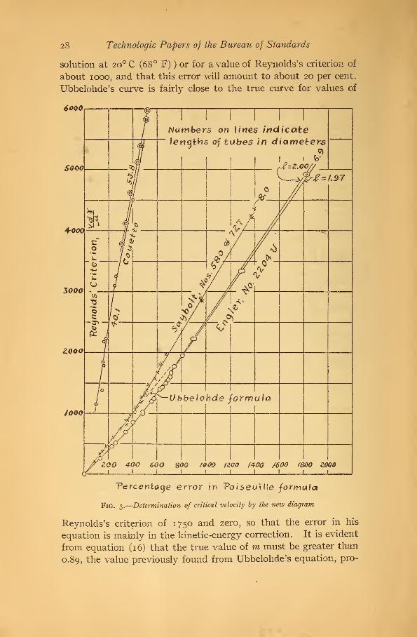
28 Technologic Papers of the Bureau of Standards
solution at 2o°C (68° F) ) or for a value of Reynolds's criterion of
about 1000, and that this error will amount to about 20 per cent.
Ubbelohde's curve is fairly close to the true curve for values of
6000
SOOO
+000
3000 ~
ZOQO
/ooo
Vercentaye error in PoiseuiUe formula
Fig. 3.
—
Determination of critical velocity by the new diagram
Reynolds's criterion of 1750 and zero, so that the error in his
equation is mainly in the kinetic-energy correction. It is evident
from equation (16) that the true value of m must be greater than
0.89, the value previously found from Ubbelohde's equation, pro-

Absolute Viscosity by Short-Tube Viscosimeters 29
vided equation (23) is used for calculating the average head, as
was done in plotting these curves.
Tests with abnormal filling have been omitted from Figs. 3 and
4 so as not to obscure the diagrams, but by plotting to a larger
loo
Vercentaqe error in VoiseuiMe formula
/oo zoo 300 400 soo
Fig. 4.
—
Determination of equations for the Engler and the Saybolt Universal
viscosimeters
scale it was found that the more nearly constant the head, the
nearer the points lie to the calculated curves for m— 1.12. That
Boussinesq's value of 1.12 is correct, within the limits of experi-
mental error, if the average head is correctly determined, is also

3° Technologic Papers of the Bureau of Standards
shown by Poiseuille's tests in Fig. i , where the lines were drawn as
calculated for m=i.i2, and are seen to agree with the experi-
mentally determined points, except for the shorter tubes and for
the higher velocities.
Values of n have been found graphically from Poiseuille's data,
with the help of equation (17), and are given in Table 5. Theyshow that n is probably variable and is always positive.
TABLE 5
Values of n from Poiseuille's Data
1,/d n
111.0 6.5
67.4 5.4
47.8 4.7
16.45 3.3
39.8 0.0
77.2 7.8
The last three values are probably less accurate because Poi-
seuille's readings were taken at higher velocities.
The value of —j- , which has been selected for the Saybolt instru-
ment as most in accordance with these considerations and with
Fig. 4, is 1.05, from which values of 1.10 and 1.11 were computed
for the Engler instrument with tube lengths assumed as 2.00 and
1.97, respectively, taking as the ratio of time, Engler, to time,
Saybolt, the experimentally determined value of 1.45.
The above assumptions in regard to I and X are equivalent to
taking a value of n of 0.8 for the Saybolt instrument and of 1.3
and 1.5, respectively, for the Engler.
In order to find values of m from equation (16), readings were
taken on Fig. 4 of the percentage error at points where Reynolds's
criterion had a value of 1000, as given in Table 6. The value for
the Engler instrument, with an assumed tube length of 1.97, is
calculated from the percentage error for an assumed length of 2,
as read from the dotted extension of the experimental curve.
TABLE 6
Percentage Error in the Poiseuille Formula When Reynolds's Criterion Has a Value
of 1000
InstrumentPercentage
error
Saybolt 385
Engler, tube length assumed, 2.00 cm 470
Engler, tube length assumed, 1.97 cm 478.7
Absolute Viscosity by Short-Tube Viscosimeters 3i
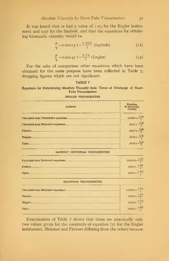
It was found that m had a value of 1 .03 for the Engler instru
ment and 0.97 for the Saybolt, and that the equations for obtain
ing kinematic viscosity would be
i-535- = 0.0021^ t
7 t
(Saybolt)
0.00147 t-^ (Engler)
(18)
(19)
For the sake of comparison other equations which have been
obtained for the same purpose have been collected in Table 7,
dropping figures which are not significant.
TABLE 7
Equations for Determining Absolute Viscosity from Times of Discharge of Short-
Tube Viscosimeters
ENGLER VISCOSIMETER
AuthorityEquation
for kinematicviscosity
Calculated from Ubbelohde's equations.
Calculated from Meissner's equations
Flowers
Higgins
Upton
SAYBOLT UNIVERSAL VISCOSIMETER
Calculated from Meissner's equations
Flowers
Upton
REDWOOD VISCOSIMETER
Calculated from Meissner's equations
Flowers
Higgins
Upton
0.00144 t-
.00157 t-
.00157 t-
.00144 t-
.00143 t
3.23
t
3J38t
3^58
t
3.22
t
3^22
t
0.00219 t-
.00219 t-
.00193 t-
1.497
t
1.497
t
1.242
t
0.00260 t-
.00263 t-
.00260 t-
.00232 t-
1.561
t
1.577
t
1.715
t
1.387
t
Examination of Table 7 shows that there are practically only
two values given for the constants of equation (5) for the Engler
instrument, Meissner and Flowers differing from the others because
32 Technologic Papers of the Bureau ofStandards
they have used only one corrective factor, /, instead of the twofactors n and m. Upton's equations for the Saybolt and Redwoodinstruments are different from those given by other authorities
because based on different experimental data. The constants
which I have calculated from Meissner's equations are the same as
those calculated by Flowers, except for the Redwood viscosimeter.
In regard to this instrument Flowers says that Meissner's con-
stants do not check very well with test results and that he has
therefore recalculated the constants.
5. EQUATIONS FOR INSTRUMENTS OF STANDARD DIMENSIONS
It must be remembered that equations (18) and (19) were de-
rived from tests on certain instruments which happened to be
available for experimental purposes, the dimensions for the Engler
instrument being given in Table 3.
Ubbelohde,35 in speaking of the report of the committee of the
American Society for Testing Materials in 1914 on comparative
data on the time of discharge of the Saybolt, Saybolt Universal,
Redwood, and Engler viscosimeters, says
:
The investigation can not, however, be considered as finished, and will not be de-
scribed in more detail here, as within a short time the standardization will be given
out by the International Petroleum Commission in Karlsruhe (Drugs, Oils, andPaints, 26, Nos. 6 and 7, 1910: Petroleum, Berlin, 6, 2029, 1911.).
Waidner states that the Bureau of Standards has entered into
negotiations with Mr. Saybolt with a view to defining the dimen-
sions of the Saybolt Universal viscosimeter and to adopting
suitable tolerances. Until this has been done equation (18) can
not be corrected to apply to a viscosimeter of standard dimensions.
It will be seen from Table 3 that the diameter of the capillary
tube of Engler viscosimeter No. 2204 U is a little too large, the
head is a little too small, and the length of tube may be a little
shorter than the mean prescribed length. The net effect of these
deviations from the average standard dimensions has been calcu-
lated by Meissner's method, and it was found that the water rate
should be 50.3 seconds. This value does not agree with the data
of Table 4 for the Engler with distilled water, but it might be
assumed that the higher water rate actually found was due to
some roughness of the inlet, which would have an effect when the
flow was in the hydraulic regime but would not appreciably
increase the time of discharge in the regime of viscous flow. If,
then, equation (19) is taken as applying to an instrument having
36 Gen. Electric Rev., loc. cit., p. 969.
Absolute Viscosity by Short-Tube Viscosimeters 33
a water rate of 50.3 seconds and is corrected in accordance with
equation (9) so that it would apply to a normal instrument
having a water rate of 51 seconds, it would become
^ =0.00145*-^ (20)
while if it is assumed that the experimentally determined water
rate of 51.3 seconds is due to causes which influence viscous as
well as hydraulic flow the equation would be
^ = 0.00148*-^ (21)y t
In view of the many uncertainties involved, neither equation (20)
or (21) can be regarded as much to be preferred to equation (19),
and they are of interest mainly as showing to what extent a change
of water rate will change the constants of equation (5)
.
X. APPLICATIONS OF THE NEW EQUATIONS FOR THEENGLER AND THE SAYBOLT UNIVERSAL VISCOSIM-ETERS
1. RATIO OF KINEMATIC VISCOSITY TO TIME OF DISCHARGE
If A and B are taken from any equation of the form of equation
(5), the kinematic viscosity may be calculated for any assumed
values of t. The change of regime must not, however, be over-
looked, and if values of the kinematic viscosity are desired for the
hydraulic regime, they can not be calculated from equations (18)
and (19). However, the value of the factor k of equation (8)
changes so rapidly with a change of t for these low viscosities that
accurate determinations can not be made with the Saybolt or
Engler viscosimeters, no matter what equations are used. Thecurves of Fig. 5 have been calculated from equations (18) and
(19) for values of the Engler time above 56 seconds and for Say-
bolt time above 31 seconds.
2. COMPARISON OF VTSCOSIMETER READINGS AT STANDARDTEMPERATURES
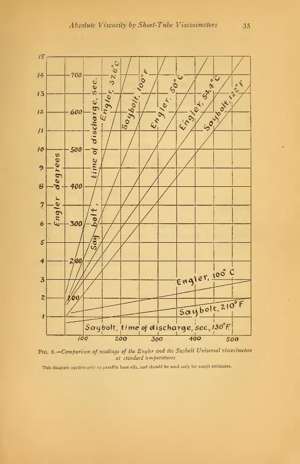
Fig. 6 may be used for conversions between the different
methods of expressing so-called viscosity, commonly in use in
the United States, 36 for approximate estimates of the readings at
commonly used temperatures, ioo°, 130 , and 210 F having
been recommended as standard temperatures by a committee of
the American Society for Testing Materials, and 50 and ioo° C
38 For other conversion diagrams, see Gill, loc. cit., p. 164-168; J. R. Battle, Lubricating Engineer's Hand-book, p. 61, 1916; Society of Automobile Engineers Data Sheets, 2, p. 18, 1916.

34 Technologic Papers of the Bureau of Standards
being commonly employed with the Engler viscosimeter. 37 Lowertemperatures are sometimes used, but with oils with a paraffin
base such determinations are of little significance on account of
the influence of the varying condition of the paraffin. Fig. 6
shows the rate of change of viscosity with change of temperature
which may be expected, on the average, with oils having a paraffin
base. Oils with an asphalt base may show a higher rate, andcompounded oils a lower rate of change.
1
I
6
Cfl
- 400
CD
ruCO
050)
iAe<
CD
-300 — o -
\*
-uj- -200 y
y
"Vo
05
/WW
Ki1
Hematici
vis*:osit LJ<U o.2 <?.3 0.4 tf.S* 4?.6 o.7
Fig. 5.
—
Ratio of kinematic viscosity to time of discharge, as calculated from the newequations
As an example of the use of Fig. 6, if an oil gives a value of 168
seconds, Saybolt time, at 130 F (54.4 C), by following the ordi-
nate of this value it may be seen that this corresponds to a value
of 4.8 Engler degrees at the same temperature. Also if the oil is
cooled to 50 C (122 F) the reading obtained with the Engler
instrument would be 5.7 and the Saybolt reading would be 198
seconds. At ioo° F (37.8 C) the corresponding values would
be 10.65 Engler degrees and 375 seconds, Saybolt. On the other
hand, if the temperature was raised to 210 F, at which, for the
purposes of this approximate estimate, the viscosity is practically
the same as at ioo° C, the readings would be 1.6 Engler degrees
and 50 seconds Saybolt.
87 D. Holde, Zeit. des Vereines deutscher Ingenieure, 56, pt. 2, p. 1461, 1912.
Absolute Viscosity by Short-Tube Viscosimeters 35
/oo zoo 300 40O BOO
Fig. 6.
—
Comparison of readings of the Engler and the Saybolt Universal viscosimeters
at standard temperatures
This diagram applies only to paraffin base oils, and should be used only for rough estimates.

36 Technologic Papers of the Bureau of Standards
XL RATIO OF TIMES OF DISCHARGE OF THE ENGLER ANDTHE SAYBOLT UNIVERSAL VISCOSIMETERS
A question of great practical importance is the ratio of the
times of flow of the Engler and Saybolt viscosimeters when the
normal volumes, 200 and 60 cc, respectively, are discharged.
For very viscous liquids, when the kinetic-energy correction is
negligible, this ratio is a constant as by equation (13), assuming
that the effect of surface tension or any other influence not con-
sidered in equation (2) is negligible or constant. Table 8 gives
the time ratios for the Engler and Saybolt instruments, and also
for the Engler and Redwood as determined by several investi-
gators.
TABLE 8
Ratios of Times of Discharge for the Engler, Saybolt, and Redwood Viscosimeters
for High Viscosities
Instruments
Ratio according to
—
Meissner Upton Flowers Higgins
Engler-Saybolt. .
.
Engler-Redwood.1.39
j
1.65
1.351.62
1.391.67 1.81
These values were obtained from the constants in their equa-
tions, omitting the last terms, which represent the kinetic-energy
correction.
On account of the large experimental error which could not be
avoided, even after the method of operation without temperature
control had been adopted, it was necessary to make a great manytests, so that, even if the plotted points appeared like the milky
way, the center line of the band would be close to the true value
and the danger of showing nonexistent humps, as with the dotted
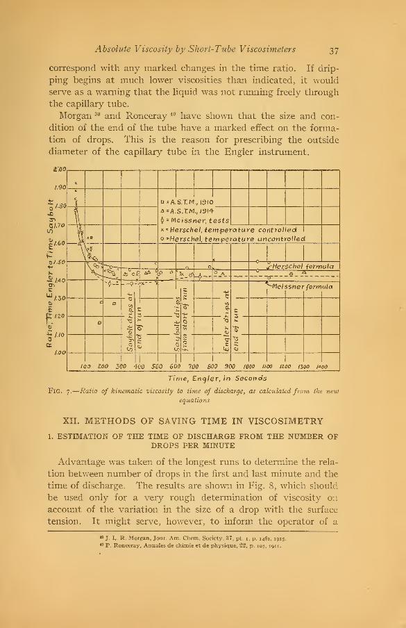
line on Fig. 7, would be avoided. The results of these tests are
shown in Fig. 7, together with those of Meissner and of committees
of the American Society for Testing Materials. 38
Taking the values of the time ratio for tests, where the time,
Engler, has a greater value than 300 seconds, and where the ratio
may be assumed nearly constant, 13 tests on Saybolt instrument
No. 727 gave an average of 1.457, and 12 tests on Saybolt No. 580
gave an average of 1.444. The points at which the instruments
begin to drip are indicated on Fig. 7, but they do not appear to
88 Proa, 10, p. 142, 1910; 14, pt. i, p. 356, 1914.
Absolute Viscosity by Short-Tube Viscosimeters 37
correspond with any marked changes in the time ratio. If drip-
ping begins at much lower viscosities than indicated, it would
serve as a warning that the liquid was not running freely through
the capillary tube.
Morgan 39 and Ronceray 40 have shown that the size and con-
dition of the end of the tube have a marked effect on the forma-
tion of drops. This is the reason for prescribing the outside
diameter of the capillary tube in the Engler instrument.
£.00
I I
D=A.S.TN. / |6>/0_
a=A.S."T/W., /9<4-
<!> = Meissner, tests
* = Herschel, temperature controlledo -Herschel, temperature uncontrolled
sHefSchel formula
a±
**
Mei ssner formula
100 100 500 400 500 600 100 800 900 WOO 1100 IZQO 1300 1400
Fig.
Time, Encjler, in Seconds
7.
—
Ratio of kinematic viscosity to time of discharge, as calculated from the newequations
XII. METHODS OF SAVING TIME IN VISCOSIMETRY
1. ESTIMATION OF THE TIME OF DISCHARGE FROM THE NUMBER OFDROPS PER MINUTE
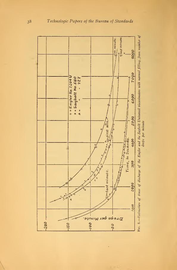
Advantage was taken of the longest runs to determine the rela-
tion between number of drops in the first and last minute and the
time of discharge. The results are shown in Fig. 8, which should
be used only for a very rough determination of viscosity on
account of the variation in the size of a drop with the surface
tension. It might serve, however, to inform the operator of a
19J. L. R. Morgan, Jour. Am. Chem. Society, 37, pt. i, p. 1461, 1915.
i0 P. Ronceray, Annales de chimie et de physique, 22, p. 107, 1911.
38 Technologic Papers of the Bureau of Standards
Absolute Viscosity by Short-Tube Viscosimeters 39
viscosimeter, after he had counted the drops in the first minute,
whether he had time to attend to other work before again taking
up his stop watch.
2. ESTIMATION OF THE NORMAL TIME OF DISCHARGE FROM THE TIMEFOUND WITH ABNORMAL VOLUMES PUT IN AND DISCHARGED
Another method of saving time with the Engler instrument is
to put more than the normal quantity of about 240 cc into the oil
container so as to increase the head, or more commonly to decrease
the time of discharge by using less than the normal volume. Thelatter method also makes it possible to use the Engler instrument
when only a small amount of the liquid is available for test.
Holde 41 put in 45 cc of oil and ran out 20 cc, but gives no reason
why he chose these amounts. He finds that the conversion
factor necessary to get the normal time for 240 cc put in and 200
cc run out is 7.24, and considers that his results, which depart byat most 6 per cent from this average value, show a satisfactory
agreement.
Ganz 42 undertook to check Holde, and also obtained conversion
factors for other abnormal volumes put in and discharged, as
shown in Table 9. Since the variations in Ganz's values are inde-
pendent of the viscosity of the oil used in the tests, they may be
considered due to experimental error.
TABLE 9
Conversion Factors Obtained by Ganz
Volume of oil put in (cubic centimeters) 45
20
45
25
50
40
60
50
120
Volume of oil discharged (cubic centimeters) 100
Factor to change time of discharge to that for 240 cc
put in and 200 cc discharged
:
Lowest 6.91
7.63
7.43
5.36
5.87
5.55
3.46
3.79
3.62
2.64
3.05
2.79
1.60
Highest 1.76
1.65
It is evident that conversion factors for any abnormal filling or
volume discharged may be calculated if the average head can be
determined. The average head, which must be used in equation
(2), is not half the sum of the initial and final heads, ht+h 2 but
can only be obtained from a formula based on an assumed relation
41 D. Holde, Mittheilungen ausden Koniglichen technischen Versuchsanstalten, 17, p. 62; 1899.
42 L. Ganz, Chemische Revue iiber die Fett-und Harz-Industrie, 6, p. 218; 1899.

40 Technologic Papers of the Bureau of Standards
between head and time of discharge. If, as in hydraulics, it is
assumed that v = c^2gh, and hence the time varies inversely as -y/h,
the average head will be 43
Meissner bases his formula for average head on equation (i)
and finds
h = K~K / x
lOge kL- lOge h2
This assumes time of discharge proportional to i/h. Since equa-
tion (23) was obtained on the assumption that the kinetic-energy
correction could be disregarded, it evidently would not strictly
apply to very fluid oils nor to water. Holde 44 investigated the
effect of an excess or deficiency in the volume put into the oil
container, but his variations in volume are not of sufficient mag-
nitude to check the accuracy of equations (22) and (23). These
equations have been used to calculate conversion factors for the
heads used by Ganz and for other abnormal heads, and the re-
sults are given in Table 10. Instead of calling the normal filling
240 cc, as given by Ganz, the value of 247 cc has been used, because
this was found to be the volume required to fill Engler visco-
simeter No. 2204 U up to the gage points. The calculations were
made for a cylinder with a flat bottom; that is, the dishing of the
bottom of the oil container was ignored. The dishing was found
to hold 31 cc, so that the calculations are in error in all cases in
which the volume left in the container at the end of the run was
less than that amount. It will be seen from the table that the
conversion factors calculated from the various equations do not
differ greatly.
Tests were made with a variety of oils using the abnormal fill-
ings indicated in Figs. 9 and 10 in order to find to what extent
Meissner's formula held good, and within what limits of viscosity.
It was to be expected that it would cease to hold good when the
kinetic-energy correction became appreciable, but that above a
certain time of discharge the factor needed to find the time for
the normal filling of 247 cc put in and 200 cc discharged would be
43 See J. T. Fanning, A Practical Treatise on Hydraulics and Water Supply Engineering, p. 221, 1893;
M. Merriman, Treatise on Hydraulics, p. 70, 1916.
44 D. Holde, Mittheilungen aus den Koniglichen technischen Versuchsanstalten, Erganzungsheft, 1, p. 5;
1895.
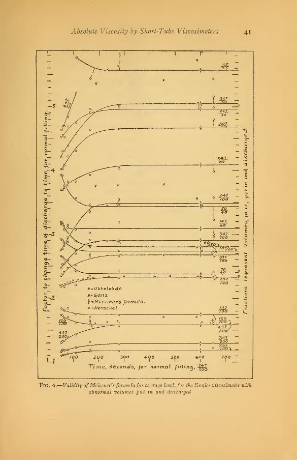
Absolute Viscosity by Short-Tube Viscosimeters 4i
-5
5—£-
,r4
w
01
5-.
en
.5 ^A = t»bbe!oWde
o -Hersche.1
300I
400I
500
•if -
Too
9 +47
)
600
200
3±Z2.0O
3:071 00 >
700I
Time, seconds, for norma\ filling, '-
FlG. 9.
—
Validity of Meissner'sformula for average head, for the Engler viscosimeter with
abnormal volumes put in and discharged

42 Technologic Papers of the Bureau of Standards
a constant. That this is the case is shown by Fig. 9, which indi-
cates that the factor may be considered constant for Engler times
of over 300 seconds with the normal filling. In drawing the curves
of Fig. 9 the tests for liquids having an Engler time of less than
55 seconds and data for fillings of — and — have been omitted.
It will be noticed that the curves turn down at the left end whenmore than 200 cc have been put into the oil container at the start,
and that they turn upward when less than 200 cc have been used.
The curves for fillings of —- and ^- are interesting because the& 100 200 &
calculated factor is practically the same for both. In drawing all
curves it has been assumed that, starting from the left end, the
curves would rise or fall, as the case might be, until tangent to
the straight line indicating the calculated value of the factor. This
procedure might be questioned in the case of those fillings in which
less than 31 cc are left in the container at the end of the run, but
has been adhered to even then on account of the lack of con-
cordance in experiments made with the more viscous oils, especially
with the smaller fillings. Ganz evidently experienced the samedifficulty. On the whole, it may be concluded that his conversion
factors should be used with considerable caution and that the
calculated values of Table 10 are in all probability much more
accurate, in cases where the Engler time is over 300 seconds. For
less viscous oils, the conversion factor is best taken from Fig. 9 or
Fig. 10. Ubbelohde 45 takes as the conversion factor when the
normal amount is put in and 100 cc discharged, a value of 2.353,
which he says is constant for Engler times of from 390 seconds
up and is less for more fluid oils. When the normal amount is
put in and 50 cc discharged, he gives 5.030 as the conversion
factor.
45 Tabellen, p. 25.
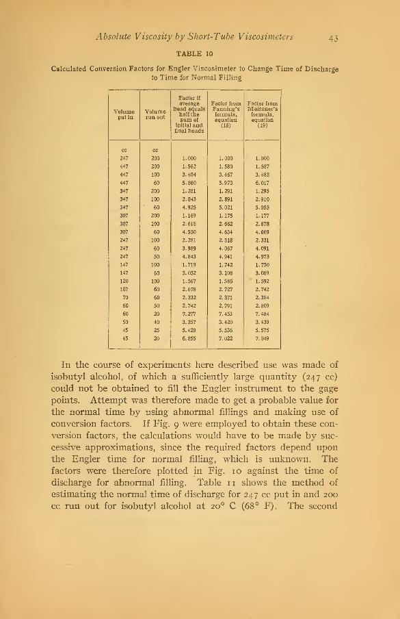
Absolute Viscosity by Short-Tube Viscosimeters
TABLE 10
43
Calculated Conversion Factors for Engler Viscosimeter to Change Time of Discharge
to Time for Normal Filling
Volumeput in
Volumerunout
Factor if
averagehead equals
half thesum of
initial andfinal heads
Factor fromFanning'sformula,equation
(18)
Factor fromMeissner'sformula,equation
(19)
cc cc
247 200 1.000 1.000 1.000
447 200 1.562 1.580 1.587
447 100 3.404 3.467 3.488
447 60 5.860 5.973 6.017
347 200 1.281 1.291 1.295
347 100 2.843 2.891 2.910
347 60 4.925 5.021 5.055
307 200 1.169 1.175 1.177
307 100 2.618 2.662 2.678
307 60 4.550 4.634 4.669
247 100 2.281 2.318 2.331
247 60 3.989 4.067 4.091
247 50 4.843 4.941 4.973
147 100 1.719 1.742 1.750
147 60 3.052 3.108 3.089
120 100 1.567 1.586 1.592
107 60 2.678 2.727 2.742
70 60 2.332 2.371 2.384
60 50 2.742 2.791 2.809
60 20 7.277 7.453 7.484
50 40 3.357 3.420 3.439
45 25 5.428 5.536 5.575
45 20 6.855 7.022 7.049
In the course of experiments here described use was made of
isobutyl alcohol, of which a sufficiently large quantity (247 cc)
could not be obtained to fill the Engler instrument to the gage
points. Attempt was therefore made to get a probable value for
the normal time by using abnormal fillings and making use of
conversion factors. If Fig. 9 were employed to obtain these con-
version factors, the calculations would have to be made by suc-
cessive approximations, since the required factors depend uponthe Engler time for normal filling, which is unknown. Thefactors were therefore plotted in Fig. 10 against the time of
discharge for abnormal filling. Table 11 shows the method of
estimating the normal time of discharge for 247 cc put in and 200
cc run out for isobutyl alcohol at 20 C (68° F). The second
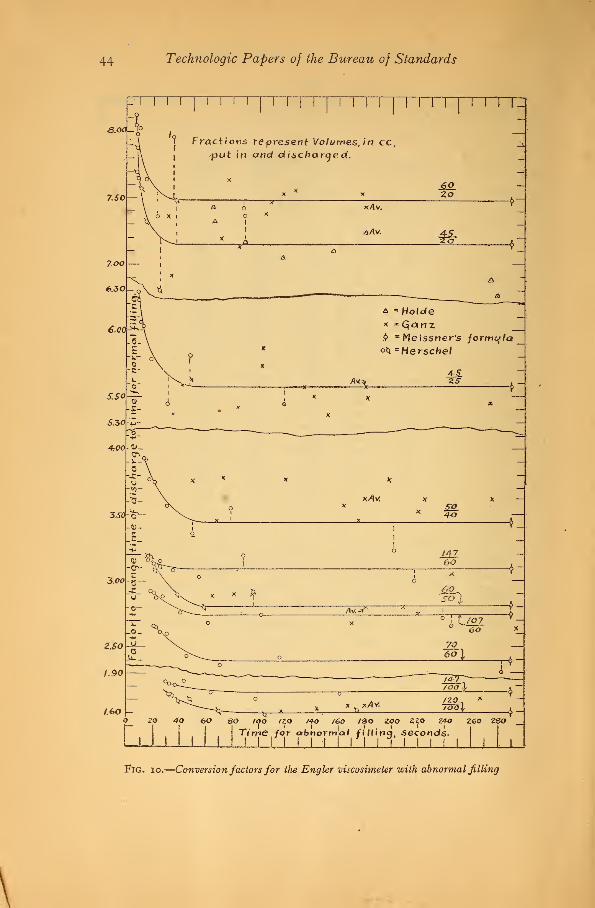
44 Technologic Papers of the Bureau of Standards
| Fractions represent Volumes, in cc,
1put in and discharged.
I II
M I I I I I J I I M I 14
Zo
£>AV. AS-za
Ami
a *Hoidex =Qanzb -Meissner's formula°t* -Herschel
zs
xAv. x x
4-0
14-7
60
Av.^
6oso I
T^m6a
* a*AV-
p 2o 4a 60 so too /zo /4o /eo /do zoo zzo z4o zeo zso
Time for abnormlal fiHinq, seconds- IMINI UM I I I I II iI I I I I ILi
Fig. io.—Conversion factors for the Engler viscosimeter with abnormal filling
\

Absolute Viscosity by Short-Tube Viscosimeters 45
point from the bottom, on the Bngler curves of Figs. 3 and 4, is
calculated from this estimated time. 48
TABLE 11
Normal Time of Discharge of Isobutyl Alcohol, at 20° C, with Engler Viscosimeter
Volume put inVolume
dischargedTime
FactorfromFig. 10
Normaltime of
discharge
cc
70
cc
60
50
40
25
20
20
sees
26.32
22.10
17.90
11.34
9.06
8.70
2.61
3.12
3.78
6.15
7.70
7.90
sees
68.6
60... 68.9
50 67.7
45 69.7
45 69.7
60. 68.8
68.9
On account of the small capacity of the oil container of the
Saybolt instrument only a few tests were made with the container
only partly full. These tests are given in Table 12, the volume
discharged being 30 cc in every test. Diagrams similar to Figs.
9 and 10 would be of little value for the Saybolt instrument, but
these tests were made to show the effect of a more constant head.
TABLE 12 k
Times of Discharge for Saybolt Universal Viscosimeters with Abnormal Volumes Putin and Discharged
Liquid Temperature Time
Viscosimeter No. 580, 44 cc put in, 30 cc discharged:
Water
°C
3
o
15
15
3
3
15
20
25
54.4
sees
18.36
Do 18.46
10 per cent ethyl alcohol 18.06
Isobutyl alcohol 25.96
Viscosimeter No. 727, 40 cc put in, 30 cc discharged:
Water 18.56
Do 18.64
10 per cent ethyl alcohol 17.98
Do 17.80
60 per cent sucrose solution 107. 86
Do 32.58
46 For the viscosity and density of isobutyl alcohol, see T. E. Thorpe and J. W. Rodger, Phil. TransR. S., 185, pt. 2, p. 538, 1894; I- Pierre and E. Puchot, Ann. de Chim. et de Phys., 22, p. 306, 1871; E. C.
Bingham and Miss J. P. Harrison. Zeit. fur physikalische Chemie, 66, p. 1, 1909.

46 Technologic Papers of the Bureau of Standards
XIII. CONCLUSION
The conclusions from this investigation for short tubes, such as
are used in the Engler and the Saybolt Universal viscosimeters,
are as follows
:
1
.
The value of the product of the velocity of flow and diameter
of tube, divided by the kinematic viscosity, must not be greater
than 800 if the flow is to be viscous rather than turbulent.
2. Consequently water is not a suitable liquid for use in finding
the relation between viscosity and time of discharge, and Ubbe-
lohde's equation and all others based upon it are seriously in
error.
3. A small but positive amount must be added to the measured
length of tube to get the effective length.
4. Boussinesq's value of 1.12 for the coefficient of the kinetic-
energy correction would be approximately applicable if the
average head could be correctly determined.
5. If the average head is determined by Meissner's formula,
which is the best available, although unsatisfactory and far from
accurate, a lower value must be used for the coefficient.
It is desirable that each operator of a viscosimeter should be
able to obtain the relation between viscosity and time of dis-
charge for his own instrument without use of the tube dimensions,
which are difficult to determine with sufficient accuracy. Tables
of data in regard to suitable liquids for this purpose are given in
Appendix 2. If Higgins's method is used, it is not necessary
to determine the tube dimensions.
Washington, April 14, 191 7. .
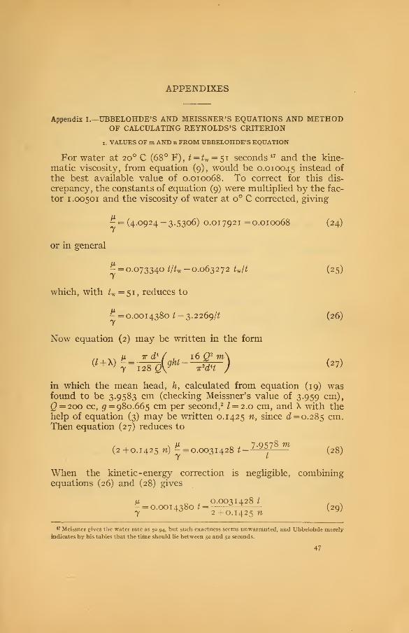
APPENDIXES
Appendix 1.—UBBELOHDE'S AND MEISSNER'S EQUATIONS AND METHODOF CALCULATING REYNOLDS'S CRITERION
x. VALUES OF m AND n FROM UBBELOHDE'S EQUATION
For water at 20 C (68° F), ^ =^ = 51 seconds 47 and the kine-
matic viscosity, from equation (9), would be 0.010045 instead of
the best available value of 0.010068. To correct for this dis-
crepancy, the constants of equation (9) were multiplied by the fac-
tor 1.00501 and the viscosity of water at o° C corrected, giving
- = (4.0924 — 3.5306) 0.01 792 1 = 0.010068 (24)
or in general
^ = 0.073340 */*w -0.063272 Ult (25)
which, with K = 51 , reduces to
-=0.0014380^-3.2269/2 (26)7
Now equation (2) may be written in the form
in which the mean head, h, calculated from equation (19) wasfound to be 3.9583 cm (checking Meissner's value of 3.959 cm),
Q = 2oo cc, £ = 980.665 cm per second, 2I = 2.0 cm, and X with the
help of equation (3) may be written 0.1425 n, since 0^ = 0.285 cm.Then equation (27) reduces to
UL 7 Q ^78 Ttt
(2+0.1425 n) -=0.0031428 t- 1^ (28)
When the kinetic -energy correction is negligible, combiningequations (26) and (28) gives
/z, 0.0031428 t
- = 0.001 4380 t =—,
(20)7 2 +0.1425 n v yj
*> Meissner gives the water rate as 50.94, but such exactness seems unwarranted, and Ubbelohde merely
indicates by his tables that the time should lie between 50 and 52 seconds.
47

48 Technologic Papers of the Bureau of Standards
from which w = 1.3021. Substituting in equation (28) this valueof n, with t = 51 when the kinematic viscosity is 0.010068, the valueof m is found to be 0.88621.
Similarly, for Engler instrument No. 2204 U, for which thediameter of the oil container is 10.584 cm and the initial head onthe lower end of the capillary tube is 5.184 cm, the avergae headwas found to be 3.9392 cm. As regards the length of tube it wasstated "the extreme length of the capillary tube was found to be20.0 mm + 0.1 mm, while the length of the capillary measuredinside between the points at the ends of the tube where the round-ing begins was found to be 1.970 mm +0.05 mm."With a mean diameter of 0.287 cm, equation (28) becomes
(/ + 0.1435 n) ^ = 0.0032158 £-7.9578 m/t (30)
It will be noted that the last term remains unchanged, being in
fact simply -——• Using the experimentally determined water
rate of 51.3 seconds, equation (30) becomes
(/ +0.1435 n) ^ = 0.16497-0.15512 m (31)
while from equation (25)
^ = 0.0014296 *- 3.2459/* (32)
By combining equations (30) and (32) it is found that if
/ = i.97, n = 1.9474 (33)
l = 2.oo, w = 1.7382 (34)
and then, with the help of equation (31), 7^=0.91748 in either
case, whether the length is 1.97 or 2 cm.
2. VALUES OF m AND n FROM MEISSNER'S EQUATION FOR THE SAYBOLT VISCO-SIMETER
From the dimensions of Saybolt viscosimeter No. 752, given byMeissner, equation (35), which is of the same form as equation
(30) of section 1, may be obtained.
(1.411 + 0.089?*)- =0.0030368/ -2.3873m/* (35)

Absolute Viscosity by Short-Tube Viscosimeters 49
Meissner gives for the Saybolt instrument the equation
(36)
h= 228.7^/
where
-=0.08019 E— 0.07013/E
3-5767=0.0015723 fe-^-1
E being the viscosity in Engler degrees. For a very viscous oil,
when the kinetic-energy correction is negligible, equation (36)simplifies to
K =t =—« = i.^qos (37)ts 228.7X2X0.0015723 oy D vo//
and from a combination of equations (35) and (37), with equation(28) of section 1
,
0.0030368(2+0.I425^E) , VK"0.0031428(1.411 +o.o89ns)
~ 1 '^°^ W>
Since the value of ue (i. e., n for the Engler instrument) is known,ns is the only unknown quantity in equation (38) , and it is foundto be 1. 2 1 09. This leaves m the only unknown quantity in equa-tion (35), if Meissner's value of £ = 28.55 *s taken for the waterrate and the kinematic viscosity is equal to 0.010068 as in section 1
.
Substituting these values m is found to be 0.87791.
3. DETERMINATION OF m AND n FROM FIG. 3
From equations (i) and (2) and the definition /*'
ft' (l+\)gk
H l(gh-mv2)
K6^J
If, in Reynolds's criterion, the viscosity is expressed as in equa-
tion (8),
-12V2(I + X)
Reynolds's criterion =d(gh _ mv2)
(40)
But from equations (1) and (2), when Reynolds's criterion is zero
and the kinetic-energy correction is zero,
-=-,- (41)\x I
so that from equation (15) the percentage error will be 100X//

IOO
50 Technologic Papers of the Bureau of Standards
under these circumstances. If the angle between the calibrationcurve of a capillary tube and the axis of abscissas is called 6 then,
t 0_ Reynolds's criterion
/V- l+*\ (42)
\M / )
from which, with the help of equations (15), (39), and (40),
tan^^ orm=^xM_ (43)loomd 100 tan 6 v^°'
4. METHOD OF CALCULATING REYNOLDS'S CRITERION AND — FROM THE QUANTI-TIES CONTAINED IN EQUATION (6)
M
vdy _ ^Qdy Kty<p
T~^aWlx-~^~ (44)
where <p is the fluidity, the reciprocal of the viscosity.
M ' Td'ghyt K' ,-:k
^T^m yip ^ (45)
Kt and K1 are constants for a given viscosimeter for a givenvolume put in and discharged, and unlike Archbutt and Deeley's
factor, k, they do not vary with the velocity. With the help of
viscosities given in Archbutt and Deeley's calibration table, page1 80, values of y may be interpolated from table on page 179, in
order to get values of Reynolds's criterion from equation (44).
In calculating — these values are not needed, as it is simpler to
use values of k = —-. The mean head was calculated from Meiss-ty
ner's formula, which, in order to save finding two natural loga-
rithms) is preferably written.
h ^h x -h2
(I)iog.(?' <46)
Appendix 2.—TABLES OF KINEMATIC VISCOSITIES AND OTHER PHYSICALCONSTANTS OF LIQUIDS USED IN VISCOSIMETRY
Bingham and Jackson 48 have given tables of fluidities, vis-
cosities, and densities of standard liquids for calibrating vis-
cometers or viscosimeters. When using short-tube instruments,
however, the kinematic viscosity, or viscosity divided by thedensity, is more often the physical constant required. Since it
appeared that Bingham and Jackson calculated viscosities from
48 E. C Bingham and R. F. Jackson, Scientific Paper No. 298, Bureau of Standards; 1917.
Absolute Viscosity by Short-Tube Viscosimeters 51
fluidities, the fluidities given in their tables have been used, in
preference to the viscosities, in calculating the kinematic vis-
cosities of Tables 13 and 14. Viscosities are given in centipoises
(cp). Since the centipoise is one-hundredth of the cgs unit of
viscosity and the fluidity is the reciprocal of the viscosity expressed
in cgs units,
viscositv, in cp 100 , . ,.-.
--A
= r, »i^ 3 rr-— 100 X kinematic viscosity
density fluidity X density J
In Tables 13 and 14, the densities of water for temperaturesup to 41 ° C (105.8° F), were taken from Chappuis 49 and those for
higher temperatures were taken from Thiesen. 49
•Densities for the alcohol and water solutions of Table 13 weretaken from the work of Osborne, 50 extrapolation being necessary
for temperatures below io° C (50 F) and above 40 C (104 F).
The constants given by Osborne were used in making these extra-
polations. The densities at o° C (32 F) obtained in this mannerare subject to error, due to the maximum in the density of waterat 4 C (39.
2
F). The magnitude of this error may be judged bycomparing, in Table 13, the densities calculated from Osborne'sdata with those calculated from the tables of Landolt-Bornstein. 51
In view of the difference between the two authorities in the density
of pure alcohol, no attempt was made to correct the extrapolated
densities of the solutions to allow for the influence of the maximumin the density of water.
The extrapolated values for densities of solutions at high tem-peratures may be compared with the values ot Schwers, 52 while
densities of pure ethyl alcohol are given by Ramsay and Young. 53
Densities of sugar solutions of Table 14 have been calculated
from the data of Plato,54 extrapolation being necessary for temper-atures above 6o° C (140 F). The change in density for a differ-
ence in temperature of 5 C (9 F) was found to be within 0.0004of the difference in density calculated from the data of Gerlach. 55
49 Circular No. 19, Bureau of Standards; pp. 42, 43, 5th ed.; 1916.50 N. S. Osborne, Scientific Paper No. 197, Bureau of Standards, pp. 424, 402; 1913.&l Physikalisch-ehemische Tabellen, p. 303; 1912.52 F. Schwers, Recueil des travaux chimiques des Pays-Bas, 28, p. 263; 1909.53 w. Ramsay and S. Young, Phil. Trans. R. S., 177, pt. i, p. 136, 1886; S. Young, Sci. Proc. Royal Dub-
lin Soc, 12, p. 441, 1909-10.54 F. Plato, Zeit. des Vereines der deutschen Zucker-Industrie 37, p. 1079, 1900; Landolt-Bornstein, loc.
at., p. 311; E. O. von Lippmann, Die Chemie der Zuckerarten, 2, p. 1078, 1904.50 Th. Gerlach, Zeit. des Vereines fur die Rubenzucker-Industrie, 14, p. 354, 1864; Dingler's Polytech-
nisches Journal, 172, p. 31, 1864.
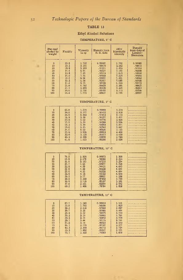
52 Technologic Papers of the Bureau of Standards
TABLE 13
Ethyl Alcohol Solutions
TEMPERATURE, 0° C
Per centalcohol byweight
FluidityViscosityincp
Density fromB. S. data
100Xkinematicviscosity
Densityfrom data of
Landolt-Bbrnstein
55.8 1.792 0. 99987 1.792 0. 9998510 30.2 3.311 .98479 3.362 . 9847220 18.8 5.319 .97551 5.453 .9755330 14.4 6.94 .96524 7.195 . 9648839 13.8 7.25 .95113 7.619 .9509240 14.0 7.14 .94930 7.524 . 9491645 14.4 6.94 . 93954 7.391 .9396250 15.2 6.58 .92917 7.080 .9292860 17.4 5.75 . 90720 6.335 .9071570 21.0 4.762 . 88420 5.386 . 8842780 27.1 3.690 . 86030 4.289 . 8604490 35.6 2.732 . 83498 3.272 . 83506100 56.4 1.773 . 80627 2.199 . 80597
lb20303940455060708090100
65.838.824.618.917.817.918.219.021.625.632.043.361.6
TEMPERATURE, 5° C
1.5192.5774.0655.295.625.595.505.264.633.9063.1252.3091.623
0.99999.98452.97413.96257. 94776. 94588. 93593.92542. 90326. 88013. 85615. 83078.80206
1.5192.6184.1735.4975.9285.9065.8715.6875.1254.4383.6502.7802.024
TEMPERATURE, 10° C
1020303940455060708090100
76.545.931.624.722.822.823.023.926.530.636.947.668.2
1.3082.1793.1654.054.394.394.354.183.773.2682.7102.1011.466
0. 99973. 98393. 97252. 95977.94431. 94238.93226. 92162. 89927. 87602. 85197. 82654. 79784
1.3082.2143.2544.2184.6454.6544.6644.5404.1963.7303.1812.5421.838
TEMPERATURE, 15° C
1020303940455060708090100
87.755.838.230.728.428.328.529.131.836.143.355.575.1
1.1401.7922.6183.263.523.533.513.443.142.7702.3091.8021.332
0. 99913. 98304. 97068. 95686. 94079. 93882.92852. 91776. 89523.87187. 84772. 82227. 79360
1.1411.8232.6973.4043.7433.7643.7793.7443.5133.1772.7242.1911.678

Absolute Viscosity by Short-Tube Viscosimeters
TABLE 13—Continued
Ethyl Alcohol Solutions—Continued
53
TEMPERATURE, 20° C
Per centalcohol byweight
FluidityViscosity
in cpDensity fromB. S. data
100Xkinematicviscosity
Densityfrom data of
Landolt-Bornstein
1020303940455060708090100
99.565.045.836.934.734.434.734.837.442.249.862.183.3
1.0051.5382.1832.712.882.912.882.872.672.3702.0081.6101.200
0.99823.98187. 96864. 95382. 93720.93518. 92472.91384.89113. 86766. 84344. 81797. 78934
1.0071.5672.2542.8413.0753.1083.1163.1443.0002.7312.3811.9691.521
TEMPERATURE, 25° C
1020303940455060708090100
111.975.655.145.942.542.541.941.744.649.157.270.291.2
0.8941.3231.8152.182.352.352.392.402.242.0371.7481.4241.096
0. 99708. 98043. 96639.95067.93353.93148. 92085. 90985. 88699. 86340. 83911.81362. 78506
0.8961.3491.8782.2922.5202.5262.5922.6362.5282.3592.0831.7511.397
TEMPERATURE, 30° C
10
20303940455060708090100
124.986.264.453.450.049.449.549.651.956.665.378.299.7
0.8011.1601.5531.872.002.022.022.021.931.7671.5311.2791.003
0.99568 0.804.97875 1.185.96395 1.611.94741 1.977. 92979 2.151. 72770 2.182.91692 2.203.90580 2.226. 88278 2.183. 85908 2.057. 83473 1.835. 80922 1.580. 78075 1.285
TEMPERATURE, 35° C
102030394045
5060708090100
138.499.475.163.358.658.357.758.060.165.473.887.2109.4
0.7231.0061.3321.581.711.721.731.721.661.5291.3551.147.914
0.99406. 97685.96134. 94403. 92597.92385.91291.90168.87851. 85470. 83029. 80478. 77641
0.7271.0301.3851.6731.8431.8571.8981.9121.8941.7891.6321.4251.177
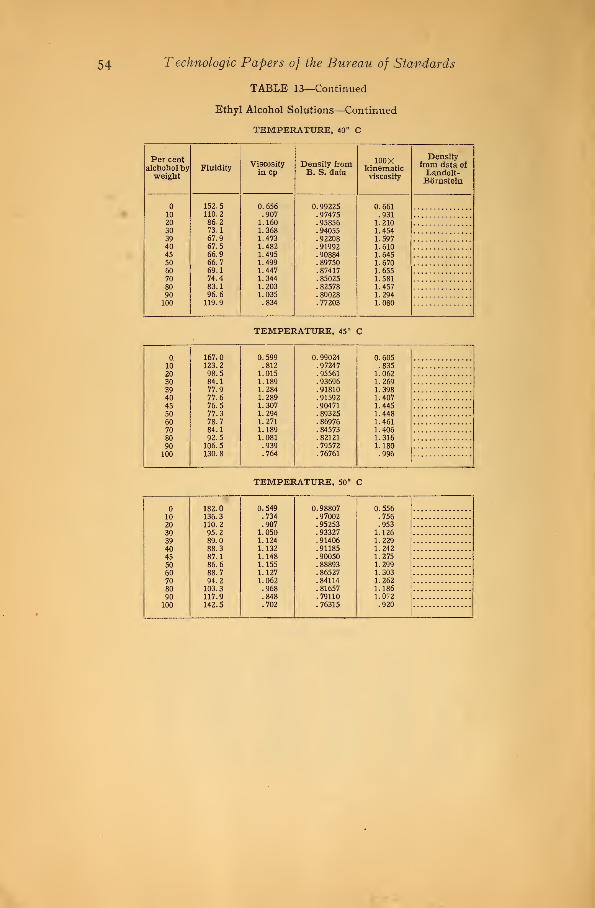
54 Technologic Papers of the Bureau of Standards
TABLE 13—Continued
Ethyl Alcohol Solutions—Continued
TEMPERATURE, 40° C
Per centalchohol byweight
FluidityViscosityin cp
Density fromB. S. data
100xkinematicviscosity
Densityfrom data of
Landolt-Bornstein
1020303940455060708090100
152.5110.286.273.167.967.566.966.769.174.483.196.6119.9
0.656.907
1.1601.3681.4731.4821.4951.4991.4471.3441.2031.035.834
0.99225.97475.95856.94055.92208.91992.90884. 89750. 87417. 85025. 82578. 80028. 77203
0.661.931
1.2101.4541.5971.6101.6451.6701.6551.5811.4571.2941.080
182.010 136.320 110.230 95.239 89.040 88.345 87.150 86.660 88.770 94.280 103.390 117.9LOO 142.5
TEMPERATURE, 45° C
0,
1020303940455060708090100
167.0123.298.584.177.977.676.577.378.784.192.5106.5130.8
0.599.8121.0151.1891.2841.2891.3071.2941.2711.1891.081.939.764
0. 99024.97247. 95561.93696.91810.91592.90471. 89325. 86976. 84573.82121. 79572. 76761
0.605.835
1.0621.2691.3981.4071.4451.4481.4611.4061.3161.180.996
TEMPERATURE, 50° C
0.549 0.98807.734 .97002.907 .95253
1.050 . 933271.124 . 914061.132 .911851.148 . 900501.155 . 888931.127 . 865271.062 . 84114.968 . 81657.848 .79110.702 . 76315
0.556.756.953
1.1261.2291.2421.2751.2991.3031.2621.1861.072.920

Absolute Viscosity by Short-Tube Viscosimeters
TABLE 14
Sucrose Solution
55
Temperature, °CPer centsucrose
by weight
10.
15.
20.
25.
30.
35.
40.
45.
50.
Fluidity
55.8026.296.77.42
65.8431.718.65.64
76.4737.7110.21
.91
87.6944.1113.391.34
99.5051.0216.131.77
111.9158.6919.282.28
124. 8966.5122.822.96
133. 4075.1226.583.77
152. 4583.8230.784.70
167. 0093.4235.135.82
182. 00103. 0740.057.14
Viscosityin cp
1.79213.80414.77
238
1. 51883.15411.56
156
1. 30772.6529.794
109.8
1. 14042.2677.468
74.6
1. 00501.9606.200
56.5
0. 89371.7045.18743.86
0. 80071.5044.382
33.78
0. 72251.3313.762
26.52
0. 65601.1933.249
21.28
0. 59881.0702.847
17.18
0. 5494.970
2.49714.01
Density
0. 999871.085461. 183491. 29560
0. 999991. 084601. 181921. 29341
0. 999731. 083531. 180201.29117
0. 999131. 082331. 178371.
0. 998231. 080941. 176481. 28644
0. 997081. 079401. 174391. 28399
0. 995681.077671. 172141. 28144
0. 994061. 075751. 169941. 27882
0. 992251. 073661. 167591.27615
0. 990241.071411. 165081. 27341
0. 988071.068981. 162481. 27058
100Xkinematicviscosity
1. 79233.504
12.48184
1.51882.9089.78
121
1. 30812.4478.299
85.11
1. 14142.0956.33857.90
1. 00681.8135.27043.92
0. 89621.5794.417
34.16
0.80431.3953.73926.36
0. 72691.2373.216
20.74
0.66111.1112.78316.67
0. 6047.9991
2.44313.49
0. 5561
.90762.148
11.02