Embed Size (px)
Citation preview
Determination of in situ deformation modulus for cemented rockfill
D. R. Tesarik, mechanical engineer, J. B. Seymour, mining engineer,
and F. M. Jones, engineering technician Spokane Research Laboratory, National Institute for Occupational Safety and Health
Spokane, WA USA
As part of safety and stability studies at three underground mines in the United States, researchers installed earth pressure cells and embedment strain gauges in cemented rockfill to measure stress and strain changes as mining progressed and the rockfill was loaded. Data from these instruments were used to calculate the in situ modulus of the rockfill for two of the mines. A three-dimensional numerical model of a cemented rockfill cap was validated with data from extensometers anchored in the mine roof and sill; this model was then used to estimate deformation modulus at the third mine because the earth pressure cells and embedment strain gauges recorded negligible changes. Rockfill binder used at these mines ranged from 4 to 8 per cent of the dry components by weight, the water-to-cement ratio was from 0.42 to1.0, and the largest aggregate size in the three mixes ranged from 5 to12 cm (2 to 4.7 in). The range of the calculated in situ deformation modulus values was large, but as expected, it was bracketed by modulus values for cemented tailings and roller-compacted concrete with similar cement contents and water-to-cement ratios. Dans le cadre d’études sur la sécurité et la stabilité de trois mines souterraines situées aux États-Unis, les chercheurs ont installé des palpeurs de pression des terres et des extensomètres d’encastrement dans les remblais cimentés afin de mesurer les variations relatives à l’effort et à la déformation des terrains durant l’exploitation minière et le chargement du remblai. Les données recueillies à l’aide de ces instruments ont servi au calcul du module in situ du remblai dans deux de ces mines. Le modèle numérique tridimensionnel de la semelle d’un remblai cimenté a été validé à partir des données recueillies par les extensomètres ancrés dans la voûte et dans la semelle de ces mines; ce modèle a ensuite été utilisé pour estimer le module de déformation à la troisième mine, étant donné que les palpeurs de pression des terres et les tensiomètres enfouis avaient relevés des variations négligeables. La matière d’agrégation de l’enrochement utilisée dans ces mines comportait entre 4 % et 8 % des composantes sèches par poids; le rapport eau-ciment se situait entre 0,42 et 1,0; et la taille des agrégats les plus gros dans ces trois mélanges était de 5 cm à 12 cm (2 po à 4,7 po). L’écart entre les valeurs calculées des modules de déformation in situ était grand, mais comme on s’y attendait, cet écart a été compensé par les valeurs modulaires des résidus cimentés et du béton tassé au rouleau avec des teneurs en ciment et des rapports eau-ciment semblables. Als Teil der Sicherheits- und Stabilitätsstudien an drei Bergwerken in den Vereinigten Staaten von Amerika installierten Forscher Erddruckgeber und Einbindungsdehnungsmesser in zementierter Steinschüttung, um Spannungs- und Dehnungsveränderungen während der fortlaufenden Bergarbeiten und der Belastung der Steinschüttung zu messen. Daten von diesen Instrumenten wurden dazu verwendet, das In-Situ-Modul der Steinschüt-ung für zwei Gruben zu berechnen. Ein dreidimensionales numerisches Modell einer zementierten Steinschüttungsschwelle wurde mit den Daten von den im Grubendach und in der Schwelle verankerten Extensometern validiert; dieses Modell wurde dann dazu eingesetzt, um das Deformationsmodul in der dritten Grube zu schätzen, da die Erddruckgeber und Einbindungsdehnungsmesser nur geringfügige Messabweichungen feststellten. Das in diesen Gruben verwendete Steinschüttungsbindemittel variierte zwischen vier und acht Prozent an Trockenkomponenten nach Gewicht, der Wasser-Zementfaktor betrug zwischen 0,42 und 1,0 und die größte Zuschlagstoff-größe in den drei Mischungen schwankte zwischen fünf und zwölf Zentimetern. Die Reichweite der berechneten Werte des In-Situ-Deformationsmoduls fiel etwas breit aus, aber es fand erwartungsgemäß eine Klammerung der Modulwerte zwischen den Zemen-trückständen und dem durch Walzen verdichteten Beton mit ähnlichem Zementanteil und Wasser-Zementfaktor statt.
1

Introduction Rockfill deformation modulus is a required component of mine design, but large-scale tests to determine this value may be impractical, and results of laboratory tests may not adequately represent the heterogeneity of the rockfill resulting from aggregate segregation when the rockfill is placed (Reschke, 1993). This problem can be addressed by placing instruments in the rockfill to measure mining-induced stress and strain. As part of a safety and stability assessment of backfill mining methods, engineers from the National Institute for Occupational Safety and Health (NIOSH) installed earth pressure cells, embedment strain gauges, and vertical fill extensometers in cemented rockfill at the Cannon, Buick, and Turquoise Ridge mines (Figure 1) with the assistance of staff from the mines. Backfill binder ranged from 4 to 8 per cent of the dry components by weight, the water-to-cement ratio was from 0.42 to1.0, and the largest aggregate size in the three mixes ranged from 5 to12 cm (2 to 4.7 in) (Table 1). In situ deformation modulus values were calculated from stress changes measured by earth pressure cells and strain changes measured by embedment strain gauges or vertical backfill extensometers at the Cannon and Buick mines. A calibrated three-dimensional, finite-difference code was used to determine the deformation modulus for the backfill at the Turquoise Ridge Mine. The authors hope that the range of in situ deformation modulus values obtained from these three case studies and previous research by others will serve as a practical guide for future backfill mix design, particularly if an instrumentation program is not planned or before instrument readings are available.
Figure 1.─Location of Cannon, Buick, and Turquoise Ridge mines in the United States. The factors affecting rockfill modulus values are water content, cementitious properties and content, aggregate particle-size distribution, aggregate strength, water quality, age, and degree of compaction. For mixtures having similar water and cement contents, the modulus of rockfill (Table 2) is likely to be greater than the modulus of cemented tailings (Table 3) and less than the modulus of roller-compacted concrete (RCC) (Table 4). Previous research supports this hypothesis.1 1Except for tangent deformation modulus values between 20 and 50 per cent measured in cemented tailings at the Lucky Friday Mine by Williams et al. (2001).
Table 1.─Components of backfill mixes for the Cannon, Buick and Turquoise Ridge mines,
percentage of total dry components Mine Coarse
aggregate Fine aggregate Cement
Flyash
Binder
1Ww/2Wb
Cannon Minus 5.1-cm (2-in) granitic alluvium, 55
Alluvial sand, 39.5
5.5 NA 5.5 1.0
Buick Minus 12.7-cm (5-in) crushed dolomite, 96
NA 4 NA 4 1.0 (approx.)
Turquoise Ridge
Minus 5.1 (2-in) crushed waste rock, 93
NA 5.8 1.95 7.8 0.42
1 Ww = Weight of water in mixture. 2 Wb = Weight of binder in mixture.
2

Table 2.─In situ deformation modulus values for cemented rockfill
Mine Coarse aggregate Fine aggregate 1Binder Age, days
Modulus average or range, MPa (psi)
Reference
Kidd Creek Minus 15-cm (6-in) crushed andesite-diorite
- 5.0 28 2,280-3,380 (330,686-490,227)
Yu 1995
Mt. Isa Minus 30-cm (11.8-in) crushed Kennedy Siltstone
Deslimed tailings
6-8 - 280 (40,610) Gonano and Kirby, 1977; Thomas et al. 1976
1Percentage of total dry components.
Table 3.─In situ deformation modulus values for cemented tailings, percentage of total dry components Mine Fine
aggregate 1Cement 1Other
binder 1Total binder
2Ww/ 3Wb
Age, days
Modulus average or range, MPa
(psi)
Reference
Lucky Friday Classified tailings
10 - 10 1.49 15 681-5,095 (98,770-738,967)
Williams et al., 2001
Garpenburg Deslimed tailings
9 - 9 2.9 “Long-term”
200 (29,007) Krauland and Stille, 1993
Western Deep Levels South
Deslimed tailings
- Slagment, lime
7 - - 30-110 (4351-15,954)
Gurtunca et al., 1993
Chimo Paste - - - - 70-105 24-51 (3481-7397)
Hassani et al., 1998
Mount Isa Deslimed tailings
4 Copper reverbatory furnace slag, 6
10 - >540 90-200 (13,053-29,008)
Gonano, 1977
1Percentage of total dry components. 2Ww = Weight of water in mixture. 3Wb = Weight of binder in mixture. RCC differs from most rockfills because the paste volume fills, or nearly fills, aggregate voids to produce a dense mixture; however, RCC generally has a maxi-mum aggregate size of 7.62 cm (3 in) and unconfined compressive strength (UCS) values in the same range as some rockfills (American Concrete Institute [ACI], 1999). Reported UCS values obtained from laboratory specimens average 11.5 per cent lower than values obtained from tests on cores retrieved from placed material (ACI, 1999). To account for a similar in situ effect on the RCC deformation modulus, laboratory values were reduced by 11.5 per cent (Figure 2).
Cannon Mine The Cannon Mine, located in central Washington, USA (Figure 1), was a joint venture between Break-water Resources, Vancouver, B.C., and Asamera Minerals, Calgary, AB, which operated the mine from 1984 to 1994. Instruments were placed in two of the mine's gold-bearing ore bodies, the B-North and the B-Neath, to monitor ground stability. These two ore bodies were developed between 61 and 313 m (200 and 1028 ft) below the surface using an overhand bench-and-fill mining method. Maximum dimensions of the shallower B-North ore body were 168 by 244 m (550 by 800 ft) in plan view with stopes arranged in parallel panels across strike. Primary stopes 7.3 m (24 ft) wide were excavated and filled with cemented backfill in
3
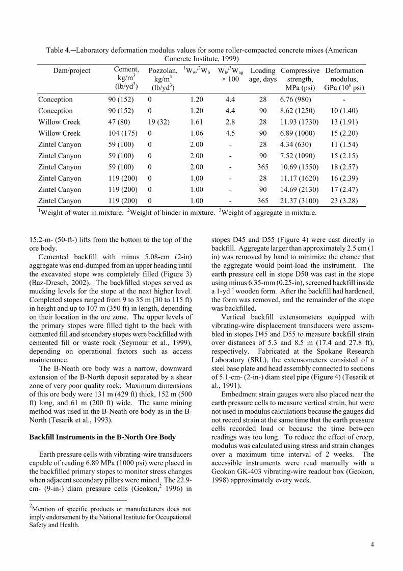
Table 4.─Laboratory deformation modulus values for some roller-compacted concrete mixes (American
Concrete Institute, 1999) Dam/project Cement,
kg/m3 (lb/yd3)
Pozzolan, kg/m3
(lb/yd3)
1Ww/2Wb Wb/3Wag × 100
Loading age, days
Compressive strength,
MPa (psi)
Deformation modulus,
GPa (106 psi)Conception 90 (152) 0 1.20 4.4 28 6.76 (980) - Conception 90 (152) 0 1.20 4.4 90 8.62 (1250) 10 (1.40) Willow Creek 47 (80) 19 (32) 1.61 2.8 28 11.93 (1730) 13 (1.91) Willow Creek 104 (175) 0 1.06 4.5 90 6.89 (1000) 15 (2.20) Zintel Canyon 59 (100) 0 2.00 - 28 4.34 (630) 11 (1.54) Zintel Canyon 59 (100) 0 2.00 - 90 7.52 (1090) 15 (2.15) Zintel Canyon 59 (100) 0 2.00 - 365 10.69 (1550) 18 (2.57) Zintel Canyon 119 (200) 0 1.00 - 28 11.17 (1620) 16 (2.39) Zintel Canyon 119 (200) 0 1.00 - 90 14.69 (2130) 17 (2.47) Zintel Canyon 119 (200) 0 1.00 - 365 21.37 (3100) 23 (3.28) 1Weight of water in mixture. 2Weight of binder in mixture. 3Weight of aggregate in mixture.
15.2-m- (50-ft-) lifts from the bottom to the top of the ore body. Cemented backfill with minus 5.08-cm (2-in) aggregate was end-dumped from an upper heading until the excavated stope was completely filled (Figure 3) (Baz-Dresch, 2002). The backfilled stopes served as mucking levels for the stope at the next higher level. Completed stopes ranged from 9 to 35 m (30 to 115 ft) in height and up to 107 m (350 ft) in length, depending on their location in the ore zone. The upper levels of the primary stopes were filled tight to the back with cemented fill and secondary stopes were backfilled with cemented fill or waste rock (Seymour et al., 1999), depending on operational factors such as access maintenance. The B-Neath ore body was a narrow, downward extension of the B-North deposit separated by a shear zone of very poor quality rock. Maximum dimensions of this ore body were 131 m (429 ft) thick, 152 m (500 ft) long, and 61 m (200 ft) wide. The same mining method was used in the B-Neath ore body as in the B-North (Tesarik et al., 1993). Backfill Instruments in the B-North Ore Body Earth pressure cells with vibrating-wire transducers capable of reading 6.89 MPa (1000 psi) were placed in the backfilled primary stopes to monitor stress changes when adjacent secondary pillars were mined. The 22.9-cm- (9-in-) diam pressure cells (Geokon,2 1996) in 2Mention of specific products or manufacturers does not imply endorsement by the National Institute for Occupational Safety and Health.
stopes D45 and D55 (Figure 4) were cast directly in backfill. Aggregate larger than approximately 2.5 cm (1 in) was removed by hand to minimize the chance that the aggregate would point-load the instrument. The earth pressure cell in stope D50 was cast in the stope using minus 6.35-mm (0.25-in), screened backfill inside a 1-yd 3 wooden form. After the backfill had hardened, the form was removed, and the remainder of the stope was backfilled. Vertical backfill extensometers equipped with vibrating-wire displacement transducers were assem-bled in stopes D45 and D55 to measure backfill strain over distances of 5.3 and 8.5 m (17.4 and 27.8 ft), respectively. Fabricated at the Spokane Research Laboratory (SRL), the extensometers consisted of a steel base plate and head assembly connected to sections of 5.1-cm- (2-in-) diam steel pipe (Figure 4) (Tesarik et al., 1991). Embedment strain gauges were also placed near the earth pressure cells to measure vertical strain, but were not used in modulus calculations because the gauges did not record strain at the same time that the earth pressure cells recorded load or because the time between readings was too long. To reduce the effect of creep, modulus was calculated using stress and strain changes over a maximum time interval of 2 weeks. The accessible instruments were read manually with a Geokon GK-403 vibrating-wire readout box (Geokon, 1998) approximately every week.
4

s Figure 2.─Deformation modulus values for cemented tailings, cemented rockfill, and roller-compacted concrete. Backfill Instruments in the B-Neath Ore Body The primary stopes in the B-Neath ore body were also instrumented with vertical backfill extensometers, embedment strain gauges, and earth pressure cells (Figure 5). Maximum ranges on the earth pressure cells were 3.45 or 6.89 MPa (500 or 1000 psi). The embedment strain gauges (Geokon model VCE-4210) were 24.4 cm (10 in) long with 5.1-cm- (2-in-) diam steel platens at each end and a measurement range of 0.635 cm (0.25 in) in compression (Geokon, 1990). Before placing the earth pressure cells and embedment strain gauges approximately 1.5 m (5 ft) below grade in the stope, they were cast in forms with a backfill mix having a maximum aggregate diameter of 1.3 cm (0.5
Figure 3.─Grain-size distributions for aggregate used in the cemented rockfill at Cannon Mine. in). When the instruments were placed in the stope, the forms were removed, and the instruments were covered with backfill using a front-end loader. The newly placed backfill was left to harden before the stope was filled to the planned elevation. The vertical backfill extensometers were installed in BX-sized diamond-drill holes with the hole collars near the other instruments. The instrument design used in the B-North ore body was revised to eliminate personnel exposure to the ribs of high, open stopes, reduce installation time, and prevent damage to the instrument during backfill placement (Tesarik et al., 1993). Laboratory Deformation Modulus Values The design UCS of 8.3 MPa (1200 psi) was based on laboratory tests of 15.2- by 30.5-cm- (6- by 12-in-) cylindrical specimens. The corresponding laboratory modulus was equal to 4031.4 MPa (584,700 psi) (Baz-Dresch, 2002). To help quantify in situ strength, 15-cm- (6-in-) diam samples were cored from two stopes where the backfill had cured for over 30 days. Average UCS for these specimens was 5.65 MPa (820 psi); the corresponding deformation modulus was 1862 MPa (270,060 psi) (Brechtel et al., 1989). To determine if specimen size influenced backfill properties, SRL conducted three UCS tests on 45.7- by 91.4-cm- (18- by 36-in-) cylindrical specimens of the same backfill
5

Figure 4.─Cross section of Cannon Mine’s B-North ore body with instrument locations. mix that had been placed in the stopes. Average UCS for these larger specimens was 4.1 MPa (600 psi), and average tangent modulus at 50 per cent of peak stress was 2251 MPa (326,500 psi), or 56 per cent of the value obtained from 15.24-cm- (6-in-) diam laboratory specimens. In Situ Deformation Modulus Values The smallest stress change used to calculate deformation modulus was 6.89 kPa (1 psi), which is the resolution of the 6.89-MPa (1000-psi) earth pressure cell. These data were then averaged for each set of backfill instruments (Table 5). Data from the earth pressure cells in stope D50 were combined with readings from the vertical fill extensometers in stope D55 because the earth pressure cell at the top of stope
Figure 5.─North-south cross section of Cannon Mine’s B-Neath ore body with instrument locations. D55 was not functioning when the backfill in stope D55 exhibited the largest strain change. This change occurred when pillar D57, which was adjacent to stope D55 and the last secondary pillar in the B-North ore body, was mined. Average calculated in situ modulii were 29, 53, and 64 per cent of the laboratory values from hand-constituted 15.2-cm (6-in), hand-constituted 45.7-cm (18-in), and cored 15.2-cm (6-in) in diam specimens, respectively. Deformation modulus calculated from the cumulative stress-versus-strain plot for data recorded during the extraction of pillar D57 was 596.0 MPa (86,440 psi) (Figure 6). The data exhibit a high linear relationship, with the square of the correlation coefficient (r2) equal to 0.98.
6

Table 5.─In situ backfill modulus values calculated from instruments installed at Cannon Mine
Instruments Max. range of EPC,1 MPa
(psi). Length of VFX,2 m (ft)
Stope Ore body
Elevation, m (ft)
Age of backfill, month3
Max stress measured by
EPC, kPa (psi)
No. of data pairs
Average modulus, MPa (psi)
St. dev., MPa (psi)
EPC VFX
6.89 (1000) 5.30 (17.4)
D45 D45
B-North
238 (780) 229 (750)
1.5-3.5 124 (18) 9 334.4 (48,500)
275.1 (39,900)
EPC VFX
6.89 (1000) 8.47 (27.8)
D50 D55
B-North
226 (740) 213 (700)
9.3-10.8 2586 (375) 7 607.4 (88,100)
549.5 (79,700)
EPC VFX
6.89 (1000) 13.59 (44.6)
X80 X80
B-Neath
152 (500) 152 (500)
5.0-10.6 834 (121) 2 4424.4 (641,700)
1869.2 (271,100)
EPC VFX
6.89 (1000) 9.75 (32.0)
X86 X86
B-Neath
110 (360) 110 (360)
7.0-8.0 200 (29) 3 2906.0 (421,500)
708.1 (102,700)
All 21 1182.5 (171,500)
1510.6 (219,100)
1 Earth pressure cell. 2 Vertical fill extensometer. 3 Approximate age of backfill when stress and strain measurements were recorded.
Figure 6.─Vertical stress in stope D50 versus vertical strain in stope D55 measured during destressing of pillar D57. The range of in situ deformation modulus is very large, with a coefficient of variation equal to 1.3. Because of this large range (Table 5), the calculated in situ modulus for the Cannon Mine brackets the modulus values obtained from laboratory tests conducted on both hand-constituted and cored specimens. The lower limit may be used for design purposes when a conservative estimate of subsidence is a primary design factor, whereas the upper limit may be more appropriate if limiting backfill stress is important.
Buick Mine The Buick Mine, located in southeast Missouri, USA (Figure 1), is one of seven mines owned and operated by The Doe Run Co. in a tabular, flat-lying deposit called the New Lead Belt. The mine uses a room-and-
pillar mining method to extract lead, zinc, and copper ore from depths ranging from 335 to 366 m (1100 to 1200 ft). Pillar recovery is achieved by using from 2 t (2.2 st) of backfill per 1 t (1.1 st) of pillar ore mined to no backfill in narrow areas with abutments or barrier pillars (Roberts et al., 1998). Area 5, with 10.7- m- (35-ft-) wide rooms ranging from 14 to 19 m (46 to 62 ft) high and the section instrumented in this study, was the first area in the New Lead Belt to use cemented backfill for pillar recovery. Backfill was spread throughout the test area with front-end loaders in 0.3- to 0.6-m (1- to 2-ft) lifts and leveled with a wheeled dozer. The final 1-m (3-ft) gap was closed using minus 5-cm (2-in) cemented waste rock placed with a slinger truck. Backfill Instruments in Test Area 5 Most of the backfill instruments were placed in the east-west backfill drifts when the fill was mid-height to the pillars, but some earth pressure cells and embed-ment strain gauges were also placed near the mine roof (Figure 7). The maximum designed displacement on the embedment strain gauges was 0.635-cm (0.25-in) in compression, and the maximum designed stress on the earth pressure cells was 6.89 MPa (1000 psi). Prior to installing these instruments, they were cast in wooden forms using minus 0.64-cm- (0.25-in-) cemented aggregate and left to cure for several weeks. The forms were removed before the instruments were secured in place with wet backfill, and the newly placed backfill was allowed to cure at least 1 day before equipment was driven over the instruments. The vertical backfill extensometers were similar to those used in the B-North ore body at the Cannon Mine (Tesarik et al., 1995).
7
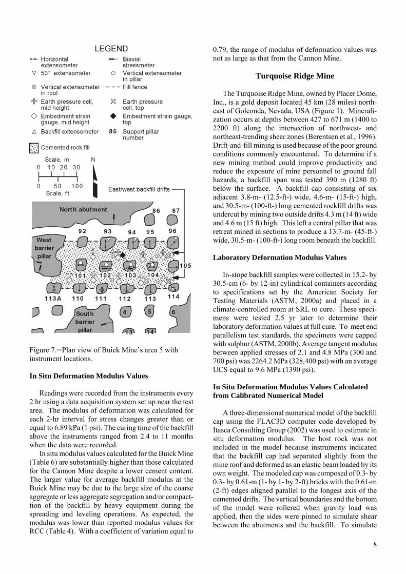
Figure 7.─Plan view of Buick Mine’s area 5 with instrument locations. In Situ Deformation Modulus Values Readings were recorded from the instruments every 2 hr using a data acquisition system set up near the test area. The modulus of deformation was calculated for each 2-hr interval for stress changes greater than or equal to 6.89 kPa (1 psi). The curing time of the backfill above the instruments ranged from 2.4 to 11 months when the data were recorded. In situ modulus values calculated for the Buick Mine (Table 6) are substantially higher than those calculated for the Cannon Mine despite a lower cement content. The larger value for average backfill modulus at the Buick Mine may be due to the large size of the coarse aggregate or less aggregate segregation and/or compact-tion of the backfill by heavy equipment during the spreading and leveling operations. As expected, the modulus was lower than reported modulus values for RCC (Table 4). With a coefficient of variation equal to
0.79, the range of modulus of deformation values was not as large as that from the Cannon Mine.
Turquoise Ridge Mine The Turquoise Ridge Mine, owned by Placer Dome, Inc., is a gold deposit located 45 km (28 miles) north-east of Golconda, Nevada, USA (Figure 1). Minerali-zation occurs at depths between 427 to 671 m (1400 to 2200 ft) along the intersection of northwest- and northeast-trending shear zones (Berentsen et al., 1996). Drift-and-fill mining is used because of the poor ground conditions commonly encountered. To determine if a new mining method could improve productivity and reduce the exposure of mine personnel to ground fall hazards, a backfill span was tested 390 m (1280 ft) below the surface. A backfill cap consisting of six adjacent 3.8-m- (12.5-ft-) wide, 4.6-m- (15-ft-) high, and 30.5-m- (100-ft-) long cemented rockfill drifts was undercut by mining two outside drifts 4.3 m (14 ft) wide and 4.6 m (15 ft) high. This left a central pillar that was retreat mined in sections to produce a 13.7-m- (45-ft-) wide, 30.5-m- (100-ft-) long room beneath the backfill. Laboratory Deformation Modulus Values In-stope backfill samples were collected in 15.2- by 30.5-cm (6- by 12-in) cylindrical containers according to specifications set by the American Society for Testing Materials (ASTM, 2000a) and placed in a climate-controlled room at SRL to cure. These speci-mens were tested 2.5 yr later to determine their laboratory deformation values at full cure. To meet end parallelism test standards, the specimens were capped with sulphur (ASTM, 2000b). Average tangent modulus between applied stresses of 2.1 and 4.8 MPa (300 and 700 psi) was 2264.2 MPa (328,400 psi) with an average UCS equal to 9.6 MPa (1390 psi). In Situ Deformation Modulus Values Calculated from Calibrated Numerical Model A three-dimensional numerical model of the backfill cap using the FLAC3D computer code developed by Itasca Consulting Group (2002) was used to estimate in situ deformation modulus. The host rock was not included in the model because instruments indicated that the backfill cap had separated slightly from the mine roof and deformed as an elastic beam loaded by its own weight. The modeled cap was composed of 0.3- by 0.3- by 0.61-m (1- by 1- by 2-ft) bricks with the 0.61-m (2-ft) edges aligned parallel to the longest axis of the cemented drifts. The vertical boundaries and the bottom of the model were rollered when gravity load was applied, then the sides were pinned to simulate shear between the abutments and the backfill. To simulate
8
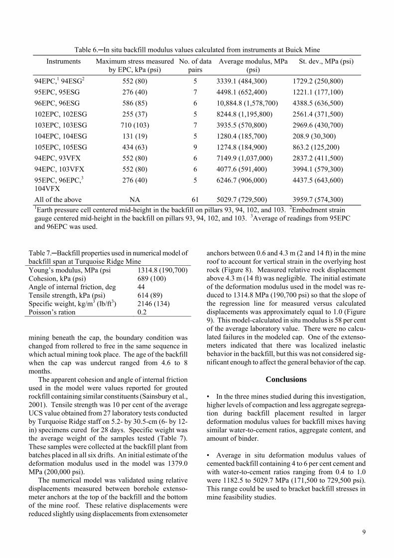
Table 6.─In situ backfill modulus values calculated from instruments at Buick Mine Instruments Maximum stress measured
by EPC, kPa (psi) No. of data
pairs Average modulus, MPa
(psi) St. dev., MPa (psi)
94EPC,1 94ESG2 552 (80) 5 3339.1 (484,300) 1729.2 (250,800) 95EPC, 95ESG 276 (40) 7 4498.1 (652,400) 1221.1 (177,100) 96EPC, 96ESG 586 (85) 6 10,884.8 (1,578,700) 4388.5 (636,500) 102EPC, 102ESG 255 (37) 5 8244.8 (1,195,800) 2561.4 (371,500) 103EPC, 103ESG 710 (103) 7 3935.5 (570,800) 2969.6 (430,700) 104EPC, 104ESG 131 (19) 5 1280.4 (185,700) 208.9 (30,300) 105EPC, 105ESG 434 (63) 9 1274.8 (184,900) 863.2 (125,200) 94EPC, 93VFX 552 (80) 6 7149.9 (1,037,000) 2837.2 (411,500) 94EPC, 103VFX 552 (80) 6 4077.6 (591,400) 3994.1 (579,300) 95EPC, 96EPC,3104VFX
276 (40) 5 6246.7 (906,000) 4437.5 (643,600)
All of the above NA 61 5029.7 (729,500) 3959.7 (574,300) 1Earth pressure cell centered mid-height in the backfill on pillars 93, 94, 102, and 103. 2Embedment strain gauge centered mid-height in the backfill on pillars 93, 94, 102, and 103. 3Average of readings from 95EPC and 96EPC was used.
Table 7.─Backfill properties used in numerical model of backfill span at Turquoise Ridge Mine Young’s modulus, MPa (psi 1314.8 (190,700)Cohesion, kPa (psi) 689 (100) Angle of internal friction, deg 44 Tensile strength, kPa (psi) 614 (89) Specific weight, kg/m3 (lb/ft3) 2146 (134) Poisson’s ration 0.2 mining beneath the cap, the boundary condition was changed from rollered to free in the same sequence in which actual mining took place. The age of the backfill when the cap was undercut ranged from 4.6 to 8 months. The apparent cohesion and angle of internal friction used in the model were values reported for grouted rockfill containing similar constituents (Sainsbury et al., 2001). Tensile strength was 10 per cent of the average UCS value obtained from 27 laboratory tests conducted by Turquoise Ridge staff on 5.2- by 30.5-cm (6- by 12-in) specimens cured for 28 days. Specific weight was the average weight of the samples tested (Table 7). These samples were collected at the backfill plant from batches placed in all six drifts. An initial estimate of the deformation modulus used in the model was 1379.0 MPa (200,000 psi). The numerical model was validated using relative displacements measured between borehole extenso-meter anchors at the top of the backfill and the bottom of the mine roof. These relative displacements were reduced slightly using displacements from extensometer
anchors between 0.6 and 4.3 m (2 and 14 ft) in the mine roof to account for vertical strain in the overlying host rock (Figure 8). Measured relative rock displacement above 4.3 m (14 ft) was negligible. The initial estimate of the deformation modulus used in the model was re-duced to 1314.8 MPa (190,700 psi) so that the slope of the regression line for measured versus calculated displacements was approximately equal to 1.0 (Figure 9). This model-calculated in situ modulus is 58 per cent of the average laboratory value. There were no calcu-lated failures in the modeled cap. One of the extenso-meters indicated that there was localized inelastic behavior in the backfill, but this was not considered sig-nificant enough to affect the general behavior of the cap.
Conclusions • In the three mines studied during this investigation, higher levels of compaction and less aggregate segrega-tion during backfill placement resulted in larger deformation modulus values for backfill mixes having similar water-to-cement ratios, aggregate content, and amount of binder. • Average in situ deformation modulus values of cemented backfill containing 4 to 6 per cent cement and with water-to-cement ratios ranging from 0.4 to 1.0 were 1182.5 to 5029.7 MPa (171,500 to 729,500 psi). This range could be used to bracket backfill stresses in mine feasibility studies.
9

Figure 8.─Elevation and plan views of extensometers and biaxial stressmeters installed in backfill cap and host rock at Turquoise Ridge Mine. • The range of in situ deformation modulus values for cemented rockfill was large, but bracketed by modulus values for cemented tailings and RCC with similar cement contents and water-to-cement ratios. • In situ deformation values were from 30 to 64 per cent of values obtained from specimens tested in the laboratory.
Figure 9.─Numerically calculated displacement versus measured displacement in backfill cap at Turquoise Ridge Mine.
Acknowledgments The authors wish to express their appreciation to Mark Mudlin and John Baz-Dresch, employed by Asamera Minerals at the Cannon Mine until its closure; Bill Lane, Tom Yanske, and Greg Sutton, The Doe Run Co.; and Rob Usher, Brian Simmons, Bob Schuler, Bert Bellows, Chris Jacobsen, Rick Smith, and John Evans of the Turquoise Ridge Mine, Placer Dome, Inc. All generously offered assistance in installing the backfill instruments, providing mine maps and mine sequence schedules, and supplying material property data. The authors would like to thank the surface and underground staff at these mines for assistance in transporting supplies, drilling holes for the instruments, stringing instrument cables, and protecting the installed instru-ments with shotcrete or backfill.
References ACI (American Concrete Institute (1999): Roller-compacted mass concrete. ACI Manual of Concrete Practice, ACI 207.5R-99, pp. 1-18. ASTM (American Society for Testing Materials) (2000a): Concrete and aggregates, designation: C 192-90a, standard practice for making and curing concrete test specimens in the laboratory. Annual Book of ASTM Standards, Vol. 4.02, pp. 300-304. ASTM (American Society for Testing Materials) (2000b): Concrete and aggregates, designation: C 617-98a, standard practice for capping cylindrical concrete specimens. Annual Book of ASTM Standards, Vol. 4.02, pp. 18-22. BAZ-DRESCH J. (2002): Personal files.
10
BERENTSEN E.J., NANNA R.F., HAZLITT J.S., and ESTES L.D. (1996): Discovery and geology of the Turquoise Ridge gold deposit. Mining Engineering, Oct., pp. 31-35. BRECHTEL, C.E., BAZ-DRESCH, J., and KNOWLSON, J.S. (1989): Application of high-strength backfill at the Cannon Mine. In: Hassani F., Scoble M., and Yu T (eds.): Innovations in Mining Backfill Technology: Proceedings of the 4th Interna-tional Symposium on Mining with Backfill, Rotterdam: Balkema, pp. 105-117. GEOKON, INC. (1996): Instruction manual, models 4800/4810/4820 vibrating wire earth pressure cells. Lebanon, NH. 23 pp. GEOKON, INC.. (1998): Instruction manual, model GK-403 vibrating wire earth readout. Lebanon, NH. 41 pp. GEOKON, INC. (1990): Instruction manual, VCE 4210, vibrating wire strain gauge. Lebanon, NH. 8 pp. GONANO L.P. (1977): Mechanical properties of cemented hydraulic fill pillars. Tech. Rep. No. 36. Melbourne: Commonwealth Scientific and Industrial Research Organization, 19 pp. GONANO L.P. and KIRBY R.W. (1977): In situ investigation of cemented rockfill in the 1100 ore body, Mount Isa Mine, Qld. Tech. Report. No. 47. Australian Commonwealth Scientific and Industrial Research Organization. GURTUNCA R.G., LEACH A.R., YORK G., and TRELOAR M.L. (1993): In situ performance of cemented backfill in a deep-level South African gold mine. In: Glen H.W. (ed.): Minefill 93, Proceedings: 5th International Symposium on Mining with Backfill, Symp. Ser. S13, Johannesburg: S. African. Institute of Mining and Metallurgy, pp. 121-128. HASSANI F., FOTOOHI K., and DOUCET C. (1998): Paste backfill performance in a narrow vein gold mine. In: Weichert D. (ed.), Proceedings: CIM, Montreal, 15 pp. HEDLEY D.F. (1993). Properties of backfill of Hecla’s Lucky Friday Mine stiff backfill project. Canadian Rockburst Research Program. 13 pp.
ITASCA CONSULTING GROUP, INC. (2002): FLAC3D Fast Lagrangian Analysis of Continua in 3 Dimensions, User’s Guide, version 2002. Available on CD. Minneapolis, MN. KRAULAND N. and STILLE H. (1993): Rock-mechanics investigations of undercut-and-fill mining at the Garpenburg Mine. In: Glen H.W. (ed.): Minefill 93, Proceedings: 5th International Symposium on Mining with Backfill, Symp. Ser. S13, Johannesburg: S. African. Institute of Mining and Metallurgy, pp. 47-54. RESCHKE A.E. (1993): The use of cemented rockfill at Namew Lake Mine, Manitoba, Canada. In: Glen H.W. (ed.): Minefill 93, Proceedings: 5th International Symposium on Mining with Backfill, Symp. Ser. S13, Johannesburg: S. African. Institute of Mining and Metallurgy, pp. 101-108. ROBERTS D.P., LANE W.L., and YANSKE T.R. (1998): Pillar extraction at the Doe Run Company 1991 to 1998. In: Bloss M. (ed.) Minefill ‘98. Proceedings of the Sixth International Symposium on Mining with Backfill, Carlton, Australia: Australasian Institute of Mining and Metallurgy, pp. 227-233. SAINSBURY D., CAI Y., and THOMPSON B. (2001): Investigation of geomechanical characteristics of stabilised rockfill. In: Stone D. (ed.): Proceedings: 7th International Symposium on Mining with Backfill, pp. 105-115. SEYMOUR J.B., TESARIK D.R., MCKIBBIN R.W., and JONES F.M. (1999): Monitoring mining-induced stress changes with the biaxial stressmeter. In: Leung C.F., Tan S.A., and Phoon K.K. (eds.): Field Measurements in Geomechanics. Proceedings: 5th International Symposium on Field Measurements in Geomechanics, Rotterdam: Balkema, pp. 55-60. TESARIK D.R., VICKERY J.D., and SEYMOUR J.B. (1991): Evaluation of in situ cemented backfill performance. U.S. Bureau of Mines Rep. Invest. 9360, 26 pp. TESARIK D.R., SEYMOUR J.B., and MUDLIN, M.E. (1993). Analysis of backfill and pillar performance in the B-Neath ore body at the Cannon Mine. In: Glen H.W. (ed.): Minefill 93, Proceedings: 5th International Symposium on Mining with Backfill, Symp. Ser. S13, Johannesburg: S. African. Institute of Mining and Metallurgy, pp. 55-64. TESARIK D.R., SEYMOUR J.B., YANSKE T.R., and MCKIBBIN R.W. (1995): Stability analysis of a backfilled room-and-pillar mine. U.S. Bureau of Mines Rep. Invest. 9565, 20 pp. THOMAS E.G., NANTEL L.H., and NOTLEY K.R.
11
(1976): Fill technology in underground metalliferous mines, Australian Mineral Foundation, Inc., p. 233. WILLIAMS T., DENTON D., SEYMOUR J.B., TESARIK D., PEPPIN C., and BAYER D. (2001): Interaction between wall rock closure, cemented backfill load, and reinforcement bolt load in an under-hand stope at the Lucky Friday Mine. In: Stone D. (ed.):
Minefill 2001: Proceedings: 7th International Symposium on Mining with Backfill: Littleton, CO: Society for Mining, Metallurgy, and Exploration, pp. 117-125. YU T.R. (1995): Consolidated rockfill. Course notes presented at Cheng-Kung University, 257 pp.
12