Embed Size (px)
Citation preview
Clemson UniversityTigerPrints
All Theses Theses
12-2017
Determination of Safe Ballasts for Anchoring EventTents by Finite Element AnalysisSandeep ManoharanClemson University
Follow this and additional works at: https://tigerprints.clemson.edu/all_theses
Part of the Civil Engineering Commons
This Thesis is brought to you for free and open access by the Theses at TigerPrints. It has been accepted for inclusion in All Theses by an authorizedadministrator of TigerPrints. For more information, please contact [email protected].
Recommended CitationManoharan, Sandeep, "Determination of Safe Ballasts for Anchoring Event Tents by Finite Element Analysis" (2017). All Theses. 2805.https://tigerprints.clemson.edu/all_theses/2805
DETERMINATION OF SAFE BALLASTS FOR ANCHORING EVENT TENTS BY
FINITE ELEMENT ANALYSIS
A Thesis
Presented to
the Graduate School of
Clemson University
In Partial Fulfillment
of the Requirements for the Degree
Master of Science
Civil Engineering
by
Sandeep Manoharan
December 2017
Accepted by:
Dr. Vincent Blouin, Committee Co-chair
Dr. Brandon Ross, Committee Co-chair
Dr. Weichiang Pang
ii
ABSTRACT
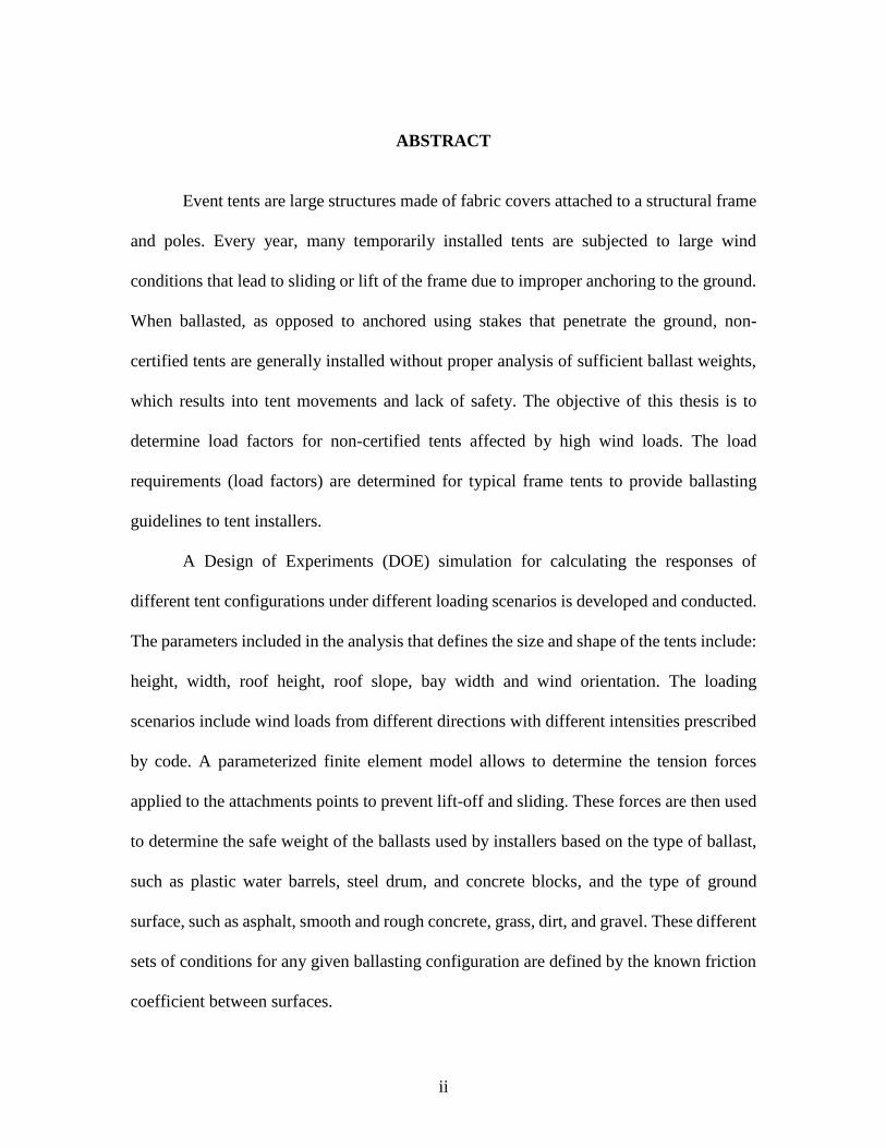
Event tents are large structures made of fabric covers attached to a structural frame
and poles. Every year, many temporarily installed tents are subjected to large wind
conditions that lead to sliding or lift of the frame due to improper anchoring to the ground.
When ballasted, as opposed to anchored using stakes that penetrate the ground, non-
certified tents are generally installed without proper analysis of sufficient ballast weights,
which results into tent movements and lack of safety. The objective of this thesis is to
determine load factors for non-certified tents affected by high wind loads. The load
requirements (load factors) are determined for typical frame tents to provide ballasting
guidelines to tent installers.
A Design of Experiments (DOE) simulation for calculating the responses of
different tent configurations under different loading scenarios is developed and conducted.
The parameters included in the analysis that defines the size and shape of the tents include:
height, width, roof height, roof slope, bay width and wind orientation. The loading
scenarios include wind loads from different directions with different intensities prescribed
by code. A parameterized finite element model allows to determine the tension forces
applied to the attachments points to prevent lift-off and sliding. These forces are then used
to determine the safe weight of the ballasts used by installers based on the type of ballast,
such as plastic water barrels, steel drum, and concrete blocks, and the type of ground
surface, such as asphalt, smooth and rough concrete, grass, dirt, and gravel. These different
sets of conditions for any given ballasting configuration are defined by the known friction
coefficient between surfaces.

iii
The developed guidelines are intended to be made available to tent installers who
will then have more confidence in the safety of any tent installation.

iv
DEDICATION
This thesis is dedicated to my family and friends who supported me throughout my
research period.
v
ACKNOWLEDGMENTS
I wish to express my sincere gratitude to Dr. Vincent Blouin, for guiding me
throughout my research phase at Clemson University.
I would also like to extend my gratitude towards the Tent Rental Division of
Industrial Fabrics Association International (IFAI) for giving me the opportunity and
means to perform this research.
In addition, I would like to thank Dr. Brandon Ross and Dr. Weichiang Pang who
rendered their help during the period of my project work.
Apart from them, I would also like to extend my thanks to Derek McMullen and
Grant Davidson who helped me in conducting experiments at Ravenel Research
Laboratory, Clemson University.
vi
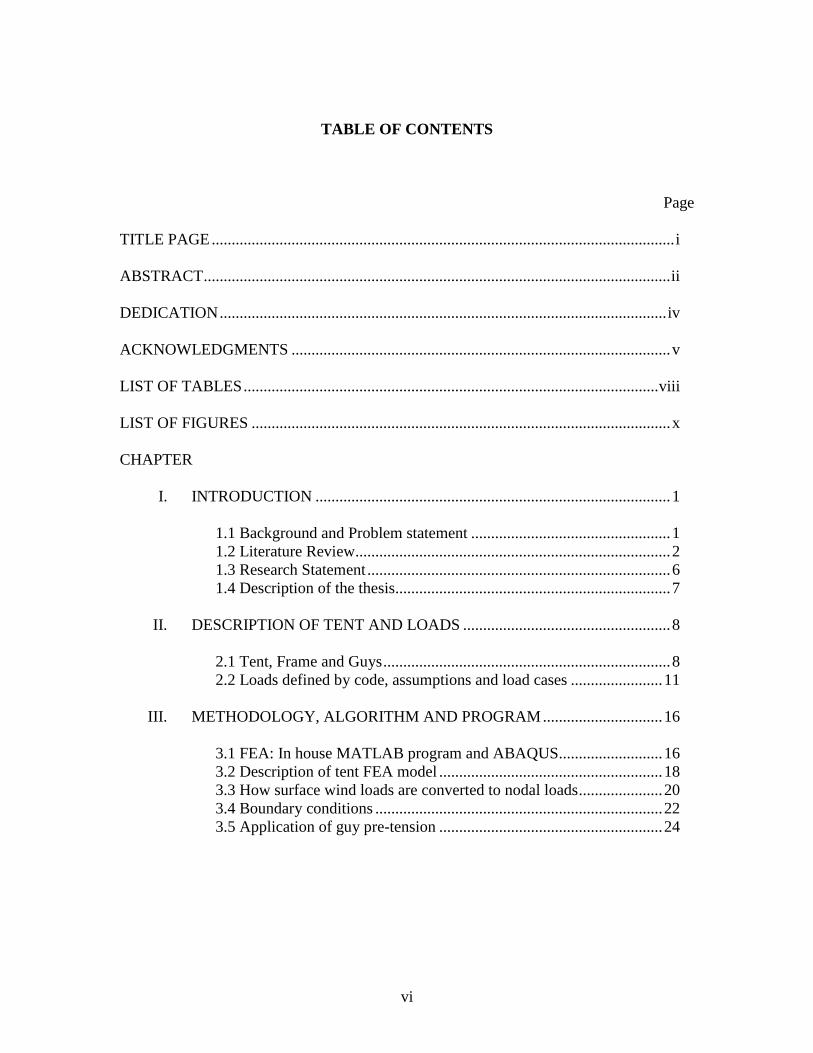
TABLE OF CONTENTS
Page
TITLE PAGE .................................................................................................................... i
ABSTRACT ..................................................................................................................... ii
DEDICATION ................................................................................................................ iv
ACKNOWLEDGMENTS ............................................................................................... v
LIST OF TABLES ........................................................................................................ viii
LIST OF FIGURES ......................................................................................................... x
CHAPTER
I. INTRODUCTION ......................................................................................... 1
1.1 Background and Problem statement .................................................. 1
1.2 Literature Review............................................................................... 2
1.3 Research Statement ............................................................................ 6
1.4 Description of the thesis..................................................................... 7
II. DESCRIPTION OF TENT AND LOADS .................................................... 8
2.1 Tent, Frame and Guys ........................................................................ 8
2.2 Loads defined by code, assumptions and load cases ....................... 11
III. METHODOLOGY, ALGORITHM AND PROGRAM .............................. 16
3.1 FEA: In house MATLAB program and ABAQUS.......................... 16
3.2 Description of tent FEA model ........................................................ 18
3.3 How surface wind loads are converted to nodal loads ..................... 20
3.4 Boundary conditions ........................................................................ 22
3.5 Application of guy pre-tension ........................................................ 24
vii
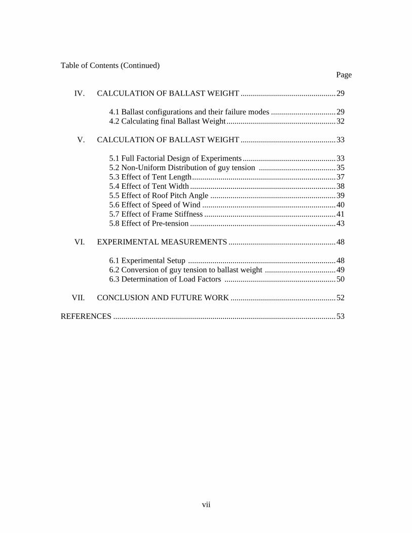
Table of Contents (Continued)
Page
IV. CALCULATION OF BALLAST WEIGHT ............................................... 29
4.1 Ballast configurations and their failure modes ................................ 29
4.2 Calculating final Ballast Weight ...................................................... 32
V. CALCULATION OF BALLAST WEIGHT ............................................... 33
5.1 Full Factorial Design of Experiments .............................................. 33
5.2 Non-Uniform Distribution of guy tension ...................................... 35
5.3 Effect of Tent Length ....................................................................... 37
5.4 Effect of Tent Width ........................................................................ 38
5.5 Effect of Roof Pitch Angle .............................................................. 39
5.6 Effect of Speed of Wind .................................................................. 40
5.7 Effect of Frame Stiffness ................................................................. 41
5.8 Effect of Pre-tension ........................................................................ 43
VI. EXPERIMENTAL MEASUREMENTS ..................................................... 48
6.1 Experimental Setup ......................................................................... 48
6.2 Conversion of guy tension to ballast weight ................................... 49
6.3 Determination of Load Factors ....................................................... 50
VII. CONCLUSION AND FUTURE WORK .................................................... 52
REFERENCES .............................................................................................................. 53
viii
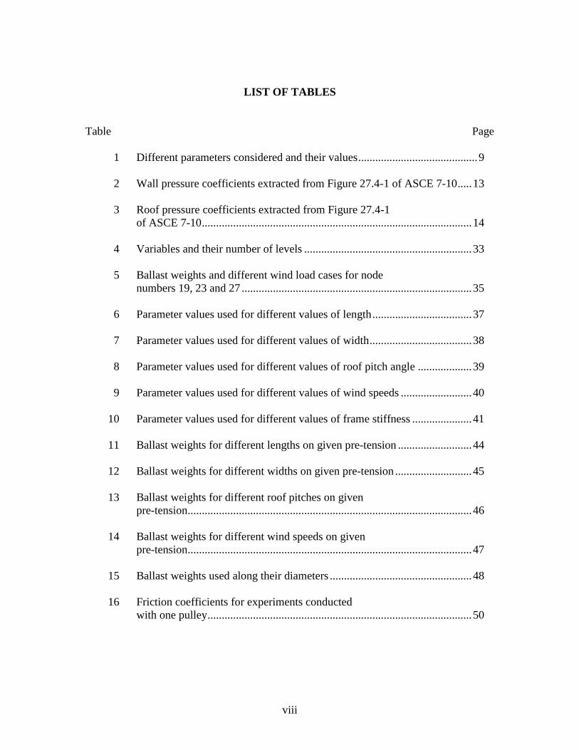
LIST OF TABLES
Table Page
1 Different parameters considered and their values .......................................... 9
2 Wall pressure coefficients extracted from Figure 27.4-1 of ASCE 7-10 ..... 13
3 Roof pressure coefficients extracted from Figure 27.4-1
of ASCE 7-10 ............................................................................................... 14
4 Variables and their number of levels ........................................................... 33
5 Ballast weights and different wind load cases for node
numbers 19, 23 and 27 ................................................................................. 35
6 Parameter values used for different values of length ................................... 37
7 Parameter values used for different values of width .................................... 38
8 Parameter values used for different values of roof pitch angle ................... 39
9 Parameter values used for different values of wind speeds ......................... 40
10 Parameter values used for different values of frame stiffness ..................... 41
11 Ballast weights for different lengths on given pre-tension .......................... 44
12 Ballast weights for different widths on given pre-tension ........................... 45
13 Ballast weights for different roof pitches on given
pre-tension.................................................................................................... 46
14 Ballast weights for different wind speeds on given
pre-tension.................................................................................................... 47
15 Ballast weights used along their diameters .................................................. 48
16 Friction coefficients for experiments conducted
with one pulley ............................................................................................. 50
ix
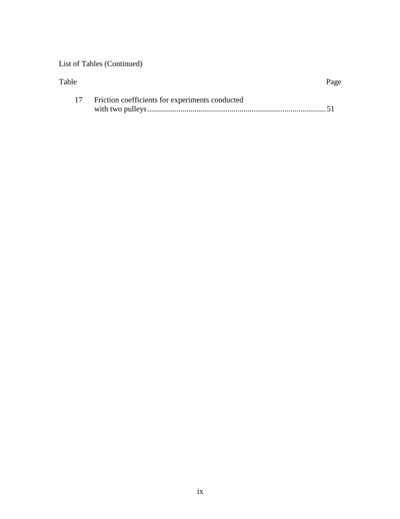
List of Tables (Continued)
Table Page
17 Friction coefficients for experiments conducted
with two pulleys ........................................................................................... 51
x
LIST OF FIGURES
Figure Page
1 Example of event tents ................................................................................... 2
2 Illustration of guy lines and ballasts .............................................................. 8
3 Diagram showing Length, Width, Roof Pitch Angle,
Ridge, Upright or Post, Guy and Guy Angle ................................................. 9
4 Flowchart with different wind load conditions ............................................ 15
5 Different tent configurations ........................................................................ 18
6 Tent with node labels ................................................................................... 19
7 Tent with element labels (beam and truss elements are
shown in blue and red, respectively)............................................................ 20
8 Tent wall denoted by color ‘green’ .............................................................. 21
9 Different wall sections with nodal forces acting on nodes .......................... 22
10 Different roof sections with nodal forces acting on nodes .......................... 22
11 Tent model showing nodes with pinned Boundary
Conditions (BC’s) ........................................................................................ 24
12 Flowchart showing sequence of MATLAB scripts interaction ................... 25
13 Guys with same color code to explain symmetry ........................................ 27
14 (A) Guy connecting upright and ground – Numerical Model
(B) Guy connecting upright and ballast – In reality .................................... 29
15 Free body diagram of the ballast due to sliding ........................................... 30
16 Free body diagram of a ballast at the onset of tilting ................................... 31
17 Tent with ‘nodes’ marked by numbers ........................................................ 36
xi
List of Figures (Continued)
Figure Page
18 Graph showing length of tent (ft)(X-axis) vs. ballast
weights (lbs)(Y-axis) ................................................................................... 38
19 Graph showing width of tent (ft)(X-axis) vs. ballast
weights (lbs)(Y-axis) ................................................................................... 39
20 Graph of pitch angle in tent roof (per 12 inches)
(X-axis) vs. ballast weights (lbs)(Y-axis) .................................................... 40
21 Graph showing wind speeds (mph)(X-axis) vs.
ballast weights (lbs)(Y-axis) ........................................................................ 41
22 Graph showing frame stiffness (‘R’ in inches)
(X-axis) vs. ballast weights (lbs)(Y-axis) .................................................... 42
23 Reaction forces of the ground to the posts – F1 is
windward post & F2 is for leeward post ...................................................... 42
24 Forces F1 (lbs)(ground reaction at windward post)
and F2 (lbs) (ground reaction at leeward post) ............................................ 43
25 Graph showing pre-tension (lbf)(X-axis) vs. ballast
weights (lbs)(Y-axis) for different lengths (ft) ............................................ 44
26 Graph showing pre-tension (lbf)(X-axis) vs. ballast
weights (lbs)(Y-axis) for different widths (ft) ............................................. 45
27 Graph showing pre-tension (lbf)(X-axis) vs. ballast
weights (lbs)(Y-axis) for different roof pitches
(per 12 inches).............................................................................................. 46
28 Graph showing pre-tension (lbf)(X-axis) vs. ballast
weights (lbs)(Y-axis) for different wind speeds (mph) ................................ 47
29 Experimental setup....................................................................................... 49
30 Force measured on load cell vs. Time graph ............................................... 49
1
CHAPTER ONE
INTRODUCTION
1.1 Background and Problem Statement
Tents offer shelter to people on a temporary basis, protection from winds and rain
during receptions, ceremonies, and other recreational and professional events. As shown
in Figure 1, tents consist of sheets of fabric attached to frames and held to the ground by
stakes or ballast weights [1]. These stakes and ballasts are generally connected to the tent
by means of ropes called lines guys.
The industry uses two types of tents: (1) engineered and certified tents, which are
generally large tents designed and extensively studied by engineering firms that specify
requirements for installation and utilization, and (2) non-certified tents, which are generally
smaller and only come with installation and utilization guidelines offered by the
manufacturer.
The research presented in this thesis is part of a larger research project sponsored
by Industrial Fabrics Association International (IFAI) [2]. IFAI is an organization that
promotes the use of specialty fabrics, including the design and manufacturing of event
tents. The larger project consists of first determining the minimum holding power required
to anchor frame tents and pole tents, and then calculate the ballast weights necessary to
achieve the holding power for any pre-selected ballasting configuration. This thesis is a
subset of the larger project as it focuses exclusively on frame tents and directly finds
appropriate ballast weights for holding non-certified frame tents to the ground under any
wind condition.
2
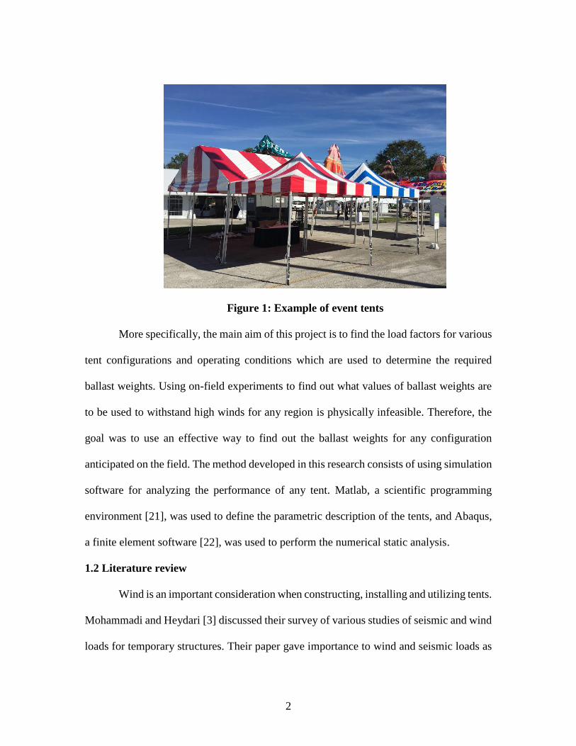
Figure 1: Example of event tents
More specifically, the main aim of this project is to find the load factors for various
tent configurations and operating conditions which are used to determine the required
ballast weights. Using on-field experiments to find out what values of ballast weights are
to be used to withstand high winds for any region is physically infeasible. Therefore, the
goal was to use an effective way to find out the ballast weights for any configuration
anticipated on the field. The method developed in this research consists of using simulation
software for analyzing the performance of any tent. Matlab, a scientific programming
environment [21], was used to define the parametric description of the tents, and Abaqus,
a finite element software [22], was used to perform the numerical static analysis.
1.2 Literature review
Wind is an important consideration when constructing, installing and utilizing tents.
Mohammadi and Heydari [3] discussed their survey of various studies of seismic and wind
loads for temporary structures. Their paper gave importance to wind and seismic loads as
3
much as live and dead loads while designing temporary structures such as scaffolds,
shelters, tents, etc. However, it was noted that live and dead loads are generally negligible
compared to wind loads in event tents since they are the lightest temporary structures.
Bolduc [4] work reiterates why designing for wind loads is a serious matter and in his paper
he examines many cases of roof collapses under wind loads, rain loads and snow loads.
Gorlin [5] emphasized that engineers from all states have considered the use of ASCE 7-
10, the minimum design loads for buildings and other structures prescribed by the
American Society of Civil Engineers [23], for designing wind loads on any structure. This
article justified the use of ASCE 7-10 in this research for calculating wind loads on tents.
St. Pierre [13] along with his team conducted wind tunnel experiments on a typical
two-story house which included conditions such as a house without surrounding houses
and another test with a house among similar houses in various subdivision types such as
grid and crescent subdivisions. His team measured pressure at 422 locations on the house
model and results proved that wind loads get reduced when surrounded by houses of similar
size. Stathopoulos [14] reiterated this statement by proving through his results that pressure
coefficients are lower than those specified by wind standards and codes of practice. For
this experiment, he carried out a wind tunnel study to examine the effects of various tree
configurations on wind-induced air infiltration and structural loading of low-rise buildings.
Therefore, in this research, assuming that tents are constructed on spread fields with no
obstruction to wind around them, considering wind loads for the design of tents to avoid
being blown away was an important task.
4
The use of a trial-and-error procedure to conduct computer simulation experiments
can be prohibitively slow. Lu [9] attributed this statement by saying that Finite Element
Analysis (FEA) is preferred due to its resilient feature and easily adapted for various
materials, shapes, etc. However, he also noted that in FEA modeling, one should be
watchful of the end results. McAlpine [6] indicated the importance of validation of the FEA
process by comparing results of FEA models to sample calculations by standard analytical
techniques. This kind of validation was shown by Mu and Wu [7] as well. They showed
that the computed internal stresses and deformations by FEA model comply with
laboratory experimental results. Bail [8] has reiterated this statement in his paper where
most of the corresponding results from testing are in agreement with those from FEA
models.
Wang [15] in his study on mechanical behaviors of a special joint between a rigid
suspension cable and a truss girder in a rigid suspension stiffened steel truss bridge
proceeded to use a three-dimensional finite element model only after results obtained from
the 3D model was as good as the results of the model test. FEA is used in many areas to
cut down the development time. Kurowski [16] proclaimed the idea of using a perfect 3D
model for FEA analysis is sometimes faced by some limitations as there will be no proper
interaction between 3D CAD model and FEA. He wrote that these CAD models are
required to have many modifications before meshing with finite elements. The main
exercise is not in obtaining the results from the FEA model and comparing with the sample
calculations by conducting experiments on real time structures. Most of the study should
be done on examining the most intricate details of the structure which will help in coming
5
up with a FEA model close to the real time working structure. An excellent match between
the FEA designed model and the structure will be possible if there is no way to propose
error.
Dinh [10] focused on tension fabric structures and showed severe geometrical and
material nonlinearities when analyzed which led him to nonlinear finite element analysis
of the membrane structure using Abaqus/standard software. This is one of the reasons why
we used Abaqus for our FEA model analysis. In addition, He [17] worked on improving
the efficiency of the construction and automated design of temporary structures where he
did the parametric and automatic modeling of 3D temporary grandstand structures with
Abaqus followed by linear and nonlinear buckling analysis of the structure.
Zhao [11] used Matlab to teach finite element analysis of statically determinate
truss structures in his class lecture for various reasons. Few of the main reasons include
flexibility in finding forces in truss members along with reaction forces at the fixed and
sliding joints. Zhao found his inspiration in Pike [12] who taught FEA for a class through
the use software. In his first few lectures he taught them to calculate forces and deflections
given geometry, constraints, and loads mathematically. Out of his three demonstrations
using software to analyze the truss using FEA, the first two cases had analyzed the way
they expected it to happen. But during his third demonstration, he proved them it was easy
for the software to analyze geometrically simple but analytically complex system. These
facts inspired this research for using Matlab and Abaqus for completing the analysis of the
tents represented as truss and frame structures.
6
Design of experiments (DOE) is a systematic method to determine the relationship
between factors affecting a process and the output of that process [20]. DOE is generally
used in design for the purpose of optimizing a system or a process. In this research,
however, it is used to determine the relationship between design parameters of tents and
the load factors and ballast weights.
1.3 Research Statement
Research Questions
Two main research questions are defined in this project and stated as follows:
(1) Assuming that the tent configuration is parametrized, can a design of
experiments be developed for a large set of parametric values in order to determine the
corresponding load factors and ballast weights?
(2) What are the load factors and ballast weights necessary to safely secure tents
under any wind conditions according to code?
Research Method
This project falls in the realm of simulation research. As described in detail in a
subsequent chapter, a Matlab script is used to develop the parametric description of any
given tent and the corresponding wind loads. It then creates the FEA input file and calls
the FEA software, Abaqus, to analyze the performance of the tent and determine the
reaction forces applied on the line guys. Finally, the Matlab script converts the reaction
forces to ballast weights using the analytical equations of the three modes of failure, i.e.,
sliding, tilting and lift of any ballast.
7
1.4 Description of the thesis
The first chapter gave an introduction into event tents and the literature related to
the analysis of these tents.
The second chapter describes the tents in more details and the design parameters to
be considered for the analysis. It also describes the sections of the codes from ASCE 7-10
which prescribes the methods for calculating the wind loads.
The third chapter describes how the finite element model was developed along with
the conversion of the surface wind loads prescribed by code to the concentrated forces
applied at the nodes of the tent frame. The first half of the third chapter deals with the
introduction to FEA and the second half deals with the procedure for obtaining results from
the FEA analysis.
The fourth chapter describes the different modes of failure of the tent that are used
to determine the ballast weights. It also presents the derivation of the equations for the
respective modes of failure.
The fifth chapter discusses the effect of different parameters of tent which can affect
the ballast weight values. The different parameters considered are tent length, tent width,
roof pitch angle, pre-tension of guys and wind speed.
The sixth chapter describes the experiments conducted on field to determine the
load factors of various types of ballasts and surfaces, which affect the final ballast weights.
Finally, the seventh chapter concludes the thesis with different observations
essential to the installation of a tent and the selection of appropriate ballast weights. This
chapter also describes future work.
8
CHAPTER TWO
DESCRIPTION OF TENTS AND LOADS
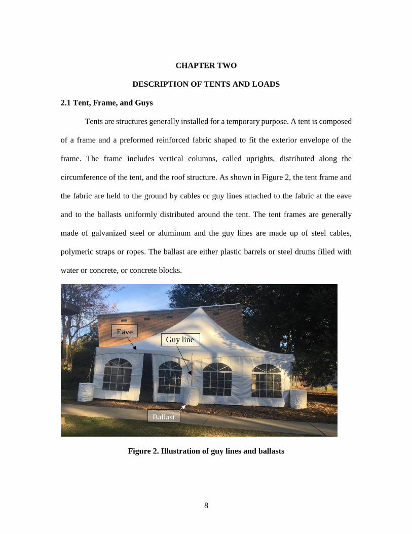
2.1 Tent, Frame, and Guys
Tents are structures generally installed for a temporary purpose. A tent is composed
of a frame and a preformed reinforced fabric shaped to fit the exterior envelope of the
frame. The frame includes vertical columns, called uprights, distributed along the
circumference of the tent, and the roof structure. As shown in Figure 2, the tent frame and
the fabric are held to the ground by cables or guy lines attached to the fabric at the eave
and to the ballasts uniformly distributed around the tent. The tent frames are generally
made of galvanized steel or aluminum and the guy lines are made up of steel cables,
polymeric straps or ropes. The ballast are either plastic barrels or steel drums filled with
water or concrete, or concrete blocks.
Figure 2. Illustration of guy lines and ballasts
Eave
Ballast
Guy line
9
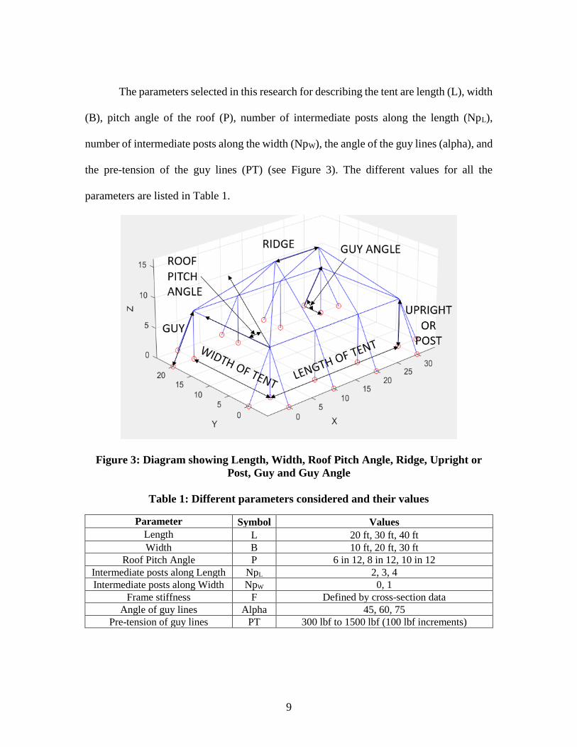
The parameters selected in this research for describing the tent are length (L), width
(B), pitch angle of the roof (P), number of intermediate posts along the length (NpL),
number of intermediate posts along the width (NpW), the angle of the guy lines (alpha), and
the pre-tension of the guy lines (PT) (see Figure 3). The different values for all the
parameters are listed in Table 1.
Figure 3: Diagram showing Length, Width, Roof Pitch Angle, Ridge, Upright or
Post, Guy and Guy Angle
Table 1: Different parameters considered and their values
Parameter Symbol Values
Length L 20 ft, 30 ft, 40 ft
Width B 10 ft, 20 ft, 30 ft
Roof Pitch Angle P 6 in 12, 8 in 12, 10 in 12
Intermediate posts along Length NpL 2, 3, 4
Intermediate posts along Width NpW 0, 1
Frame stiffness F Defined by cross-section data
Angle of guy lines Alpha 45, 60, 75
Pre-tension of guy lines PT 300 lbf to 1500 lbf (100 lbf increments)
10
The tent frame used can either be a tubular cross-section, C-channel, I-beam or T-
beam. In this research, it is assumed that the type of cross-section does not affect the ballast
weights and it is assumed to be a tubular cross-section defined by inner and outer diameters.
As the dimensions of the tent vary, the size of the frame cross-section may vary
accordingly. The frame connections are assumed to be beam connections, i.e., rigid
connections with transfer of moments. The stiffness of the fabric is neglected compared to
the overall stiffness of the frame. The tent fabric is attached to the frame using Velcro loops
around the frame elements, which means that the fabric may not be fully attached along
the length of the frame elements. It is assumed, however, that all corners are secured and
rigidly connected.
The fabric must be tightened for stability and aesthetic purposes by applying pre-
tension in all guy lines. The pre-tension is applied during installation by tightening the guy
lines. Pre-tensioning of guys is a long process that is achieved manually by the installer
who must go around the tent to tighten each guy until a pre-tension of 100 lbs to 1500 lbs
is applied in each guy depending on the size of the tent.
The roof of the tent is generally fully enclosed. The vertical walls, however, may
be entirely closed, partially opened, or entirely opened for ventilation and circulation. The
tent is considered enclosed, partially enclosed, and open, respectively. In this research, it
is assumed that the tents are partially enclosed since the flexibility of the fabric allows
significant entry of air at the space between the fabric and the floor. In any case, this
assumption is more conservative than the open configuration since it leads to higher wind
loads and therefore higher ballast weights.
11
2.2 Loads defined by code, assumptions and load cases
The wind loads are calculated as per ASCE 7-10 [18] included in Appendix A of
this thesis. The procedure used for analyzing these non-certified tents was Main Wind-
Force Resisting System (MWFRS) method as opposed to Components & Cladding (C&C)
method under the assumption that the overall frame stiffness is greater than overall fabric
stiffness. Per ASCE 7-10, C&C method is appropriate for elements having a tributary less
than 700 square feet; for this reason, it is suggested that future research can include the
C&C method for analyzing these non-certified tents. The wind is considered flowing
parallel or perpendicular to the ridge of the tent. The wind load parameters are taken from
chapters 26 and 27 of ASCE 7-10, which are included in Appendix 1 for completeness.
The wind loads are dependent on the following parameters,
• Basic wind speed, V (Section 26.5),
• Wind directionality factor, Kd (Section 26.6),
• Exposure category (Section 26.7),
• Velocity pressure exposure coefficient, Kz (Section 27.3)
• Topographic factor, Kzt (Section 26.8),
• Gust-effect factor (Section 26.9),
• Enclosure classification (Section 26.10), and
• Internal pressure coefficient, (GCpi) (Section 26-11).
Basic wind speed, V (Section 26.5 of ASCE 7-10) – The wind velocity is taken
from the speed maps or the wind speed website where the latitude and longitude of the
12
desired location can be entered and the wind speed for different risk categories are
presented. In this research, 30 to 70 mph were considered with increments of 10 mph.
Wind directionality factor, Kd (Section 26.6 of ASCE 7-10) – This factor is taken
from Table 26.6-1 of ASCE 7-10. Since the tent falls under the category Main Wind Force
Resisting System (MWFRS), Kd has a value of 0.85.
Exposure category (Section 26.7 of ASCE 7-10) – The tent is analyzed for the worst
condition where there are no obstructions, which corresponds to category D.
Velocity pressure exposure coefficient, Kz (Section 27.3 of ASCE 7-10) – Choosing
the exposure category D (assuming it is installed on a flat site, unobstructed area around
the tent), the Kz value differs according to the height of the tent and is taken from Table
27.3.1 of ASCE 7-10.
Topographic factor, Kzt (Section 26.8 of ASCE 7-10) – The value for Kzt is taken
as 1, since it is assumed that tent is situated on level ground.
Gust-effect factor (Section 26.9 of ASCE 7-10) – The factor for tents is taken as 1
as they are considered as flexible buildings.
Enclosure classification (Section 26.10 of ASCE 7-10) – As mentioned earlier, in
this research, it is assumed that the tents are considered partially enclosed.
Internal pressure coefficient, (GCpi) (Section 26-11 of ASCE 7-10) – As tents are
considered partially enclosed, GCpi is defined as +/- 0.55. This means that two cases are
considered: +0.55 for outward internal pressure and -0.55 for inward internal pressure.
The velocity pressure, qz, evaluated at height z measured from the ground is
calculated by the following equation:
13
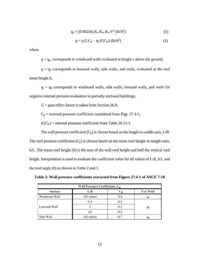
qz = (0.00256).Kz.Kzt.Kd.V2 (lb/ft2) (1)
p = q.G.Cp – qi.(GCpi) (lb/ft2) (2)
where
q = qz, corresponds to windward walls evaluated at height z above the ground,
q = qh corresponds to leeward walls, side walls, and roofs, evaluated at the roof
mean height h,
qi = qh corresponds to windward walls, side walls, leeward walls, and roofs for
negative internal pressure evaluation in partially enclosed buildings,
G = gust-effect factor is taken from Section 26.9,
Cp = external pressure coefficient considered from Figs. 27.4-1,
(GCpi) = internal pressure coefficient from Table 26.11-1.
The wall pressure coefficient (Cp) is chosen based on the length-to-width ratio, L/B.
The roof pressure coefficient (Cp) is chosen based on the mean roof height-to-length ratio,
h/L. The mean roof height (h) is the sum of the wall roof height and half the vertical roof
height. Interpolation is used to evaluate the coefficient value for all values of L/B, h/L and
the roof angle (θ) as shown in Table 2 and 3.
Table 2: Wall pressure coefficients extracted from Figure 27.4-1 of ASCE 7-10
14
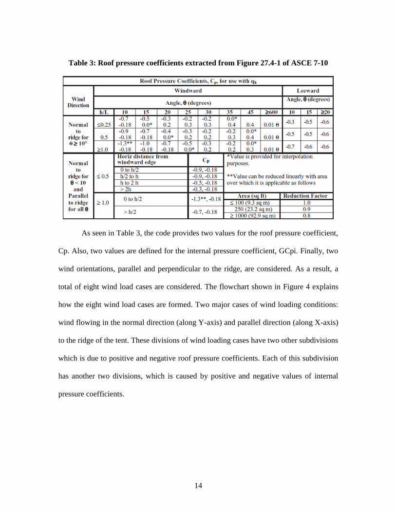
Table 3: Roof pressure coefficients extracted from Figure 27.4-1 of ASCE 7-10
As seen in Table 3, the code provides two values for the roof pressure coefficient,
Cp. Also, two values are defined for the internal pressure coefficient, GCpi. Finally, two
wind orientations, parallel and perpendicular to the ridge, are considered. As a result, a
total of eight wind load cases are considered. The flowchart shown in Figure 4 explains
how the eight wind load cases are formed. Two major cases of wind loading conditions:
wind flowing in the normal direction (along Y-axis) and parallel direction (along X-axis)
to the ridge of the tent. These divisions of wind loading cases have two other subdivisions
which is due to positive and negative roof pressure coefficients. Each of this subdivision
has another two divisions, which is caused by positive and negative values of internal
pressure coefficients.
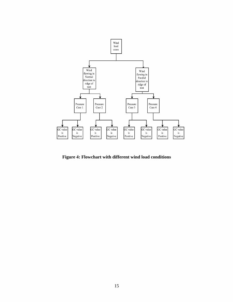
15
Figure 4: Flowchart with different wind load conditions
16
CHAPTER THREE
METHODOLOGY, ALGORITHM AND PROGRAM
3.1 FEA: In house MATLAB program and ABAQUS
Hinton and Owen [19] described FEA as a numerical technique for the solving
partial differential equations subject to known boundary and initial conditions. In recent
years, FEA has been used extensively as a solution technique for many advanced
engineering problems.
Per the authors mentioned above, the basic steps involved in the development of a
typical finite element computational model for the analysis of a tent are given below.
• The first step is to define the geometry of the frame structure as a set of connected
linear segments.
• The structure is then divided into a mesh of finite elements. In this research,
conventional two-node linear beam elements are used.
• The system is assumed to be in static equilibrium, i.e., does not vary with time.
• The stiffness matrix ‘K(e)’ and the load vector ‘f(e)’ for each finite element are calculated
and integrated together into a comprehensive stiffness matrix ‘K’ and load vector ‘f’
based on the element connectivity.
• The boundary conditions are then applied by removing the rows and columns of ‘K’
and ‘f’ corresponding to the constrained degrees of freedom. In this research, the
footings of all uprights are assumed to be fixed to the ground. Also, the guys’
attachment points to ballasts are assumed to be fixed to the ground as pinned
connections.
17
• The static equilibrium equation ‘Ka = f’, where ‘a’ is the displacement vector of all
nodes, is solved for ‘a’ by inverting the global matrix ‘K’.
• After evaluating ‘a’, the reaction at nodes, stresses, strains of elements may be
evaluated, as well as the reaction forces in all guy lines.
At the beginning of this project, an in-house FEA script programmed in Matlab was
used to conduct the analysis. It was fast and convenient since the whole process was done
within the Matlab environment. However, this existing Matlab FEA software did not have
the ability to model the non-symmetrical elastic behavior of the guy lines’ material. More
specifically, the guy lines are supposed to work in tension but not in compression. This
means that the material stiffness should be response-dependent, i.e., non-zero under tensile
deformation and zero under compressive deformation. In practice, the guy lines that are on
the windward side of the tent are usually in tension and the guy lines that are on the leeward
side of the tent are generally loose and slack and does not contribute to the stability of the
tent. Since this nonlinear behavior of the guy lines’ material could not be modelled with
the in-house Matlab FEA, Abaqus was used as an alternative.
Abaqus [22] is a well-accepted commercial FEA software that has many advanced
features, including the ability to model nonlinear behavior of materials. The interface
between Matlab and Abaqus is fairly straightforward and does not present any major road
block. As mentioned above, Matlab creates the FEA input data file for any given tent design
and calls Abaqus to run the analysis and output results. Matlab then reads the output results
and post-processes the information.
18
Note that the FEA analysis used in this research is slightly more complicated than
a simple static analysis. It includes multiple steps with one FEA in each step in order to
apply the desired pre-tension of the guy lines. This is due to the fact that applying a pre-
tension corresponds to reducing the length of the guy lines until the desired pre-tension
value is achieved. Since this process is response-dependent, it must be done in several
steps. This process is described in Section 3.4.
3.2 Description of tent FEA model
Four tent configurations, represented in Figure 5, are considered in this research. The
first configuration is a simple tent with a gable roof along the entire length of the tent. This
means that the roof has two sides sloped at a desired angle. The second configuration has
a hip roof, which has all four sides sloped at a desired angle. In this case, the roof pitch
corresponds to the angle of the two roof planes that are parallel to the length of the tent.
The angle of the other two roof places is generally not a dependent variable and is therefore
not part of the discussion. The third configuration has intermediate posts between the
exterior posts and has a gable roof. Finally, the fourth configuration has intermediate posts
and a hip roof.
Figure 5: Different tent configurations
19
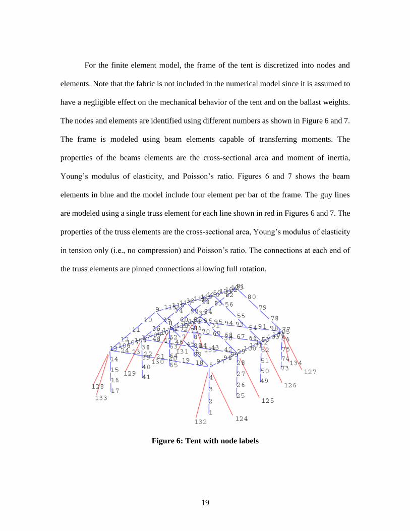
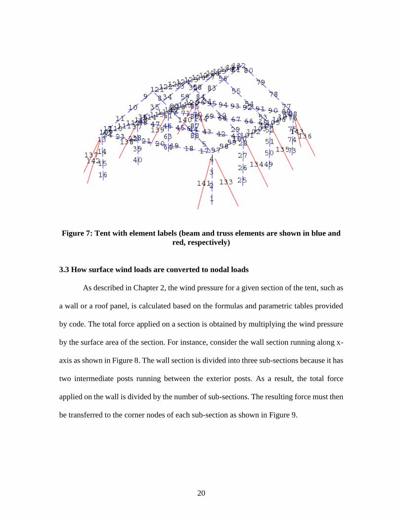
For the finite element model, the frame of the tent is discretized into nodes and
elements. Note that the fabric is not included in the numerical model since it is assumed to
have a negligible effect on the mechanical behavior of the tent and on the ballast weights.
The nodes and elements are identified using different numbers as shown in Figure 6 and 7.
The frame is modeled using beam elements capable of transferring moments. The
properties of the beams elements are the cross-sectional area and moment of inertia,
Young’s modulus of elasticity, and Poisson’s ratio. Figures 6 and 7 shows the beam
elements in blue and the model include four element per bar of the frame. The guy lines
are modeled using a single truss element for each line shown in red in Figures 6 and 7. The
properties of the truss elements are the cross-sectional area, Young’s modulus of elasticity
in tension only (i.e., no compression) and Poisson’s ratio. The connections at each end of
the truss elements are pinned connections allowing full rotation.
Figure 6: Tent with node labels
20
Figure 7: Tent with element labels (beam and truss elements are shown in blue and
red, respectively)
3.3 How surface wind loads are converted to nodal loads
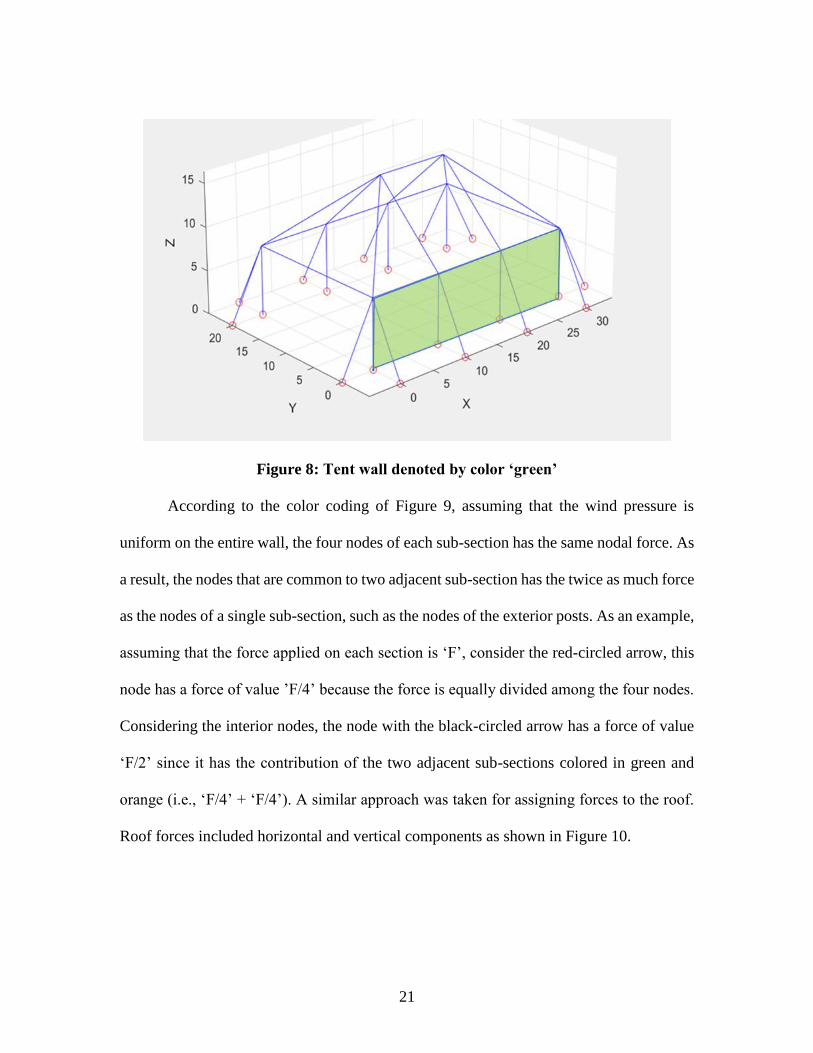
As described in Chapter 2, the wind pressure for a given section of the tent, such as
a wall or a roof panel, is calculated based on the formulas and parametric tables provided
by code. The total force applied on a section is obtained by multiplying the wind pressure
by the surface area of the section. For instance, consider the wall section running along x-
axis as shown in Figure 8. The wall section is divided into three sub-sections because it has
two intermediate posts running between the exterior posts. As a result, the total force
applied on the wall is divided by the number of sub-sections. The resulting force must then
be transferred to the corner nodes of each sub-section as shown in Figure 9.
21
Figure 8: Tent wall denoted by color ‘green’
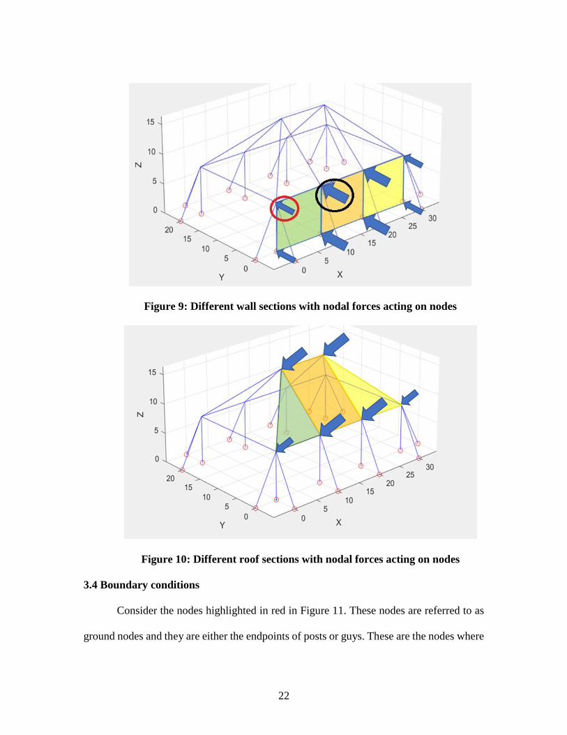
According to the color coding of Figure 9, assuming that the wind pressure is
uniform on the entire wall, the four nodes of each sub-section has the same nodal force. As
a result, the nodes that are common to two adjacent sub-section has the twice as much force
as the nodes of a single sub-section, such as the nodes of the exterior posts. As an example,
assuming that the force applied on each section is ‘F’, consider the red-circled arrow, this
node has a force of value ’F/4’ because the force is equally divided among the four nodes.
Considering the interior nodes, the node with the black-circled arrow has a force of value
‘F/2’ since it has the contribution of the two adjacent sub-sections colored in green and
orange (i.e., ‘F/4’ + ‘F/4’). A similar approach was taken for assigning forces to the roof.
Roof forces included horizontal and vertical components as shown in Figure 10.
22
Figure 9: Different wall sections with nodal forces acting on nodes
Figure 10: Different roof sections with nodal forces acting on nodes
3.4 Boundary conditions
Consider the nodes highlighted in red in Figure 11. These nodes are referred to as
ground nodes and they are either the endpoints of posts or guys. These are the nodes where
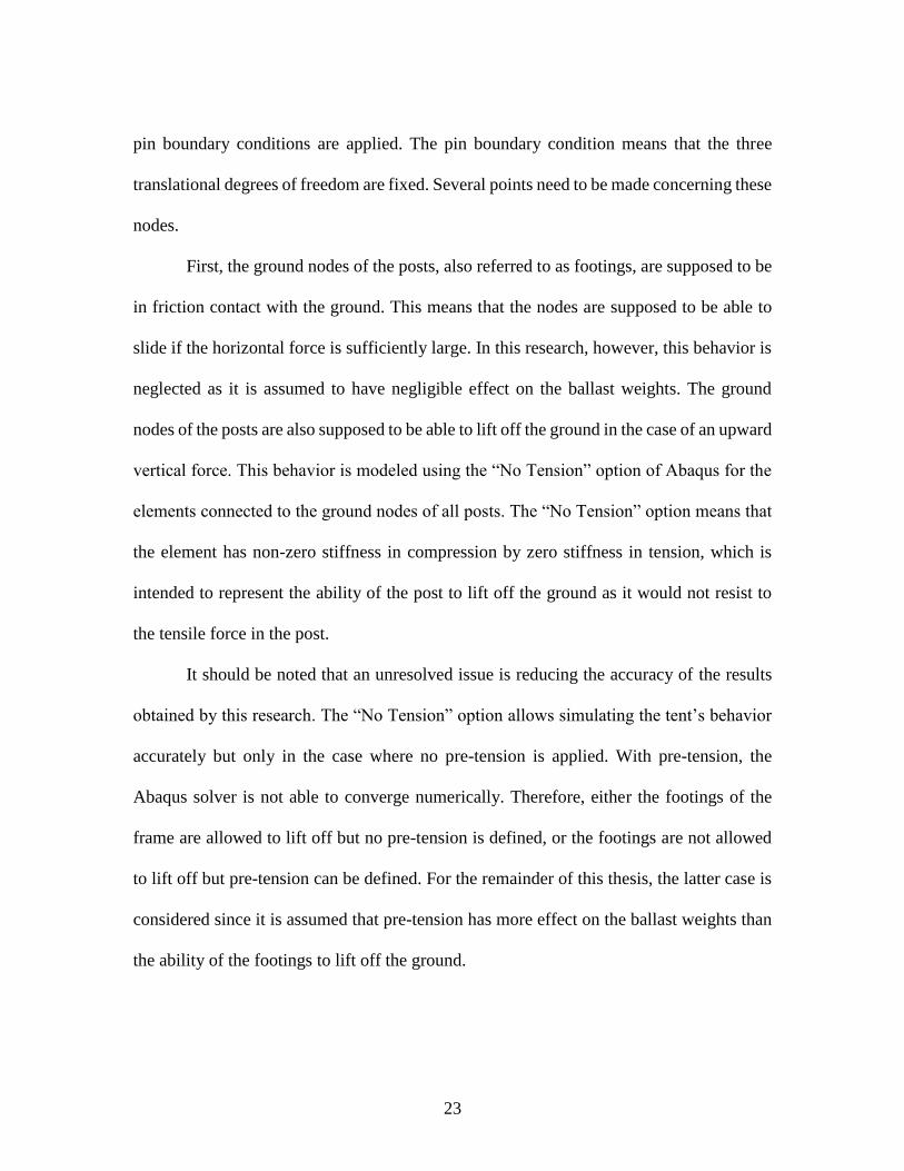
23
pin boundary conditions are applied. The pin boundary condition means that the three
translational degrees of freedom are fixed. Several points need to be made concerning these
nodes.
First, the ground nodes of the posts, also referred to as footings, are supposed to be
in friction contact with the ground. This means that the nodes are supposed to be able to
slide if the horizontal force is sufficiently large. In this research, however, this behavior is
neglected as it is assumed to have negligible effect on the ballast weights. The ground
nodes of the posts are also supposed to be able to lift off the ground in the case of an upward
vertical force. This behavior is modeled using the “No Tension” option of Abaqus for the
elements connected to the ground nodes of all posts. The “No Tension” option means that
the element has non-zero stiffness in compression by zero stiffness in tension, which is
intended to represent the ability of the post to lift off the ground as it would not resist to
the tensile force in the post.
It should be noted that an unresolved issue is reducing the accuracy of the results
obtained by this research. The “No Tension” option allows simulating the tent’s behavior
accurately but only in the case where no pre-tension is applied. With pre-tension, the
Abaqus solver is not able to converge numerically. Therefore, either the footings of the
frame are allowed to lift off but no pre-tension is defined, or the footings are not allowed
to lift off but pre-tension can be defined. For the remainder of this thesis, the latter case is
considered since it is assumed that pre-tension has more effect on the ballast weights than
the ability of the footings to lift off the ground.
24
Figure 11: Tent model showing nodes with pinned Boundary Conditions (BC’s)
Concerning the ground nodes of each guy line, as explained in Chapter 4, the
ballasts are not physically modeled. Instead, the guy lines are assumed to go from the top
of a post (i.e., eave of the tent) to the ground with a pin boundary condition at the ground.
3.5 Application of guy pre-tension
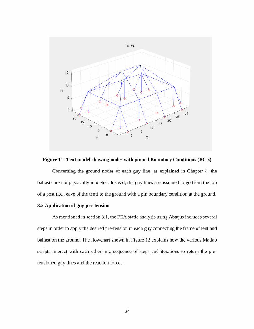
As mentioned in section 3.1, the FEA static analysis using Abaqus includes several
steps in order to apply the desired pre-tension in each guy connecting the frame of tent and
ballast on the ground. The flowchart shown in Figure 12 explains how the various Matlab
scripts interact with each other in a sequence of steps and iterations to return the pre-
tensioned guy lines and the reaction forces.
25
Figure 12: Flowchart showing the sequence of Matlab scripts and Abaqus
The different design parameters are obtained by the ‘Main Program’ from the ‘input
data file’ and these parameter values are used in turn by the ‘Preprocessor’. The
‘Preprocessor’ creates the ‘FEA input file’ with the input from the ‘Load module’ which
has the path to all possible wind load configurations.
In the flowchart, the ‘Load Module’ interacts with one of the configurations –
‘Wind Load Case #1’ to apply one loading configuration out of the eight possible loading
configurations available. In this particular case - ‘Wind Load Case #1’, corresponds to a
partially enclosed building condition with wind flowing in the direction parallel to the ridge
of the tent and with a GCpi value of +0.55. For each trial containing a new dataset of
26
parameter values, the ‘FEA Input File’ is updated with a new set of nodes, elements,
properties, boundary conditions, and forces.
In the model, the pre-tension of a guy line is achieved by applying a displacement
boundary condition that corresponds to translating the ground node of the guy line into the
ground in the direction parallel to the guy line. This is exactly equivalent to reducing the
length of the guy line to tension it. The issue is that the amount of displacement is a priori
unknown since it depends on the position of the guy line, the stiffness of the guy line’s
material, and the overall stiffness. This is the reason why the pre-tension is applied using
several steps.
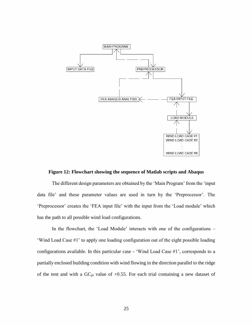
The guys are divided into several groups based on position and symmetry. In the
case of a tent with two intermediate posts in length and none in width, as shown in Figure
13, there are three groups of guys. They are (1) the guys at corners in longitudinal direction
(shown in green), (2) the guys at corners in transversal direction (shown in red), and (3)
the intermediate guys between corners in transversal direction (shown in blue) as shown in
Figure 13.
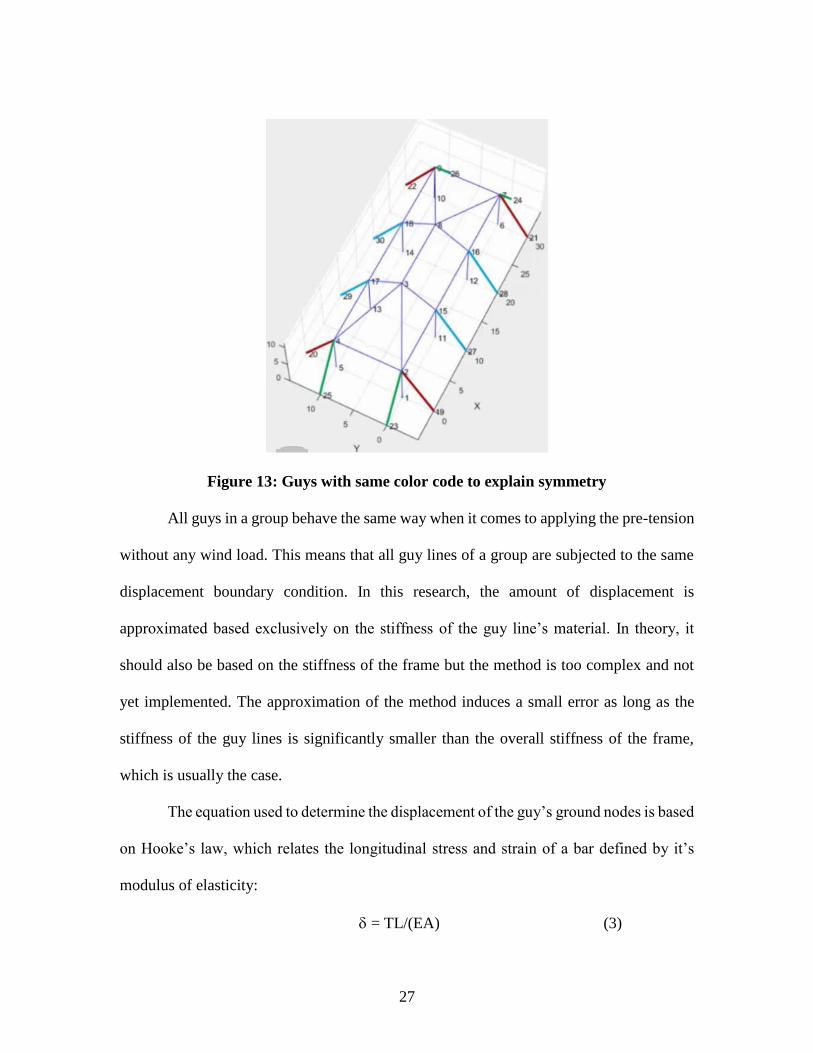
27
Figure 13: Guys with same color code to explain symmetry
All guys in a group behave the same way when it comes to applying the pre-tension
without any wind load. This means that all guy lines of a group are subjected to the same
displacement boundary condition. In this research, the amount of displacement is
approximated based exclusively on the stiffness of the guy line’s material. In theory, it
should also be based on the stiffness of the frame but the method is too complex and not
yet implemented. The approximation of the method induces a small error as long as the
stiffness of the guy lines is significantly smaller than the overall stiffness of the frame,
which is usually the case.
The equation used to determine the displacement of the guy’s ground nodes is based
on Hooke’s law, which relates the longitudinal stress and strain of a bar defined by it’s
modulus of elasticity:
= TL/(EA) (3)
28
where
is the downward displacement applied at the guy’s ground node in the direction
of the guy,
T is the desired pre-tension of the guy line,
L is the undeformed length of the guy line,
E is Young’s modulus of elasticity of the guy line’s material, and
A is the cross-sectional area of the guy line.For instance, if the tent height
is 8 feet and the guy angle is 60 degrees, the length is L = 9.24 ft. If the guy line’s material
is a polymeric strap of cross-sectional area A = 0.021 ft2 and modulus of elasticity E =
2.1e8 lbf/ft2, assuming that the desired pre-tension is T = 300 lbf, the required displacement
is = 300*9.24/0.021/2.1e8 = 6.29e-4 ft. When applying this displacement of the ground
node of each guy of a given group, the actual tension ends up being about 292 lbs, which
is close enough to the desired pre-tension of 300 lbf.
After pre-tensioning the guys, the ‘main program’ interacts with the ‘FEA Abaqus
Analysis’ to calculate the actual pre-tension and verify that it is close enough to the desired
value for each guy line. The wind loads are then applied and the reaction forces are
calculated by the FEA for all ground nodes, including the ground nodes of the guy lines
and the ground nodes of the posts. At the end of this procedure, an output file is created
with displacement of all nodes and the three components of the reaction forces. This file is
then used to calculate the heaviest ballast weight for the worst wind loading configuration.
29
CHAPTER FOUR
CALCULATION OF BALLAST WEIGHT
4.1 Ballast configurations and their failure modes
In this research, it is assumed that the guy line is always attached to the top at the
center of the ballast. Three failure modes are considered – ballast sliding, tilting, and lift.
The equations used to find the minimum ballast weight to prevent each of the three failure
modes are given below.
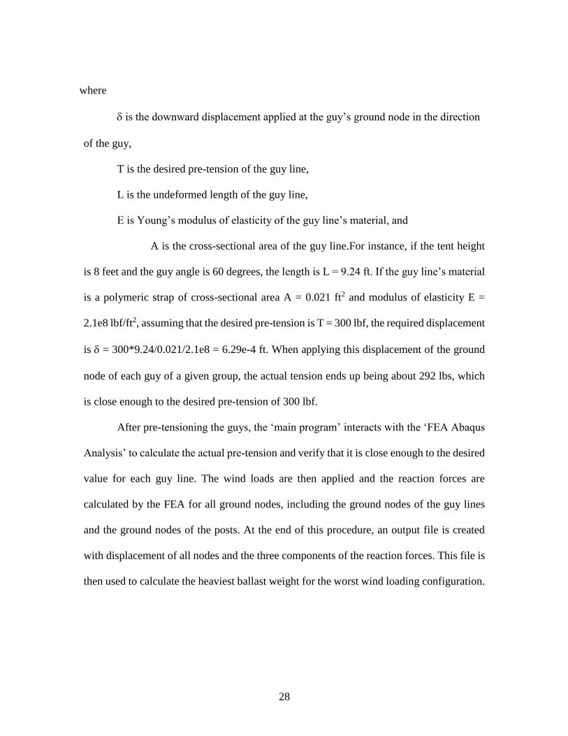
Figure 14: (A) Guy connecting upright and ground – Numerical Model
(B) Guy connecting upright and ballast – In reality
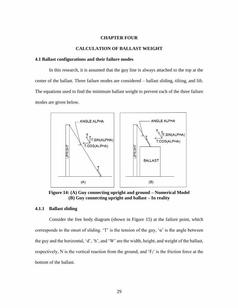
4.1.1 Ballast sliding
Consider the free body diagram (shown in Figure 15) at the failure point, which
corresponds to the onset of sliding. ‘T’ is the tension of the guy, ‘α’ is the angle between
the guy and the horizontal, ‘d’, ‘h’, and ‘W’ are the width, height, and weight of the ballast,
respectively, N is the vertical reaction from the ground, and ‘Ff’ is the friction force at the
bottom of the ballast.
30
Figure 15: Free body diagram of the ballast due to sliding
The tension of the guy can be resolved into horizontal and vertical components
Tcos(α) and Tsin(α). At the onset of sliding, the frictional force is equal to the sum of
vertical forces multiplied by the load factor and considering static equilibrium, the sum of
all horizontal forces must be equal to zero,
N – W + Tsin(α) = 0 (4)
Ff – µN = 0 (5)
Ff = µ [W – Tsin(α)] (6)
Ff – [Tcos(α)] = 0 (7)
Solving for the ballast weight ‘W’ using the above last two equations, the weight of
ballast is derived as,
W = [Tcos(α) / µ] + [Tsin(α)] (8)
The weight of the ballast ‘Wi’ (to be decided by the tent installer) should always be greater
than the theoretical ballast weight ‘W’ to avoid sliding.
31
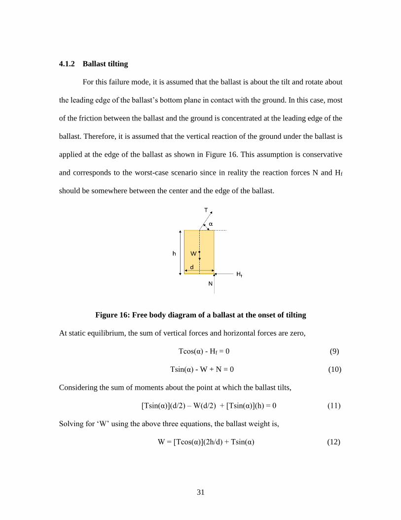
4.1.2 Ballast tilting
For this failure mode, it is assumed that the ballast is about the tilt and rotate about
the leading edge of the ballast’s bottom plane in contact with the ground. In this case, most
of the friction between the ballast and the ground is concentrated at the leading edge of the
ballast. Therefore, it is assumed that the vertical reaction of the ground under the ballast is
applied at the edge of the ballast as shown in Figure 16. This assumption is conservative
and corresponds to the worst-case scenario since in reality the reaction forces N and Hf
should be somewhere between the center and the edge of the ballast.
Figure 16: Free body diagram of a ballast at the onset of tilting
At static equilibrium, the sum of vertical forces and horizontal forces are zero,
Tcos(α) - Hf = 0 (9)
Tsin(α) - W + N = 0 (10)
Considering the sum of moments about the point at which the ballast tilts,
[Tsin(α)](d/2) – W(d/2) + [Tsin(α)](h) = 0 (11)
Solving for ‘W’ using the above three equations, the ballast weight is,
W = [Tcos(α)](2h/d) + Tsin(α) (12)
32
The weight of the ballast ‘Wi’ (to be decided by the tent installer) should always be greater
than ‘W’ to avoid tilting.
4.1.3 Ballast lifting
The last failure mode which needs to be considered is to the vertical lift of the
ballast. The weight of the ballast must be greater than the vertical force components of the
tension at the top of the ballast. This is explained by the equation,
W = T.sin(α) (13)
The weight of the ballast ‘Wi’ (to be decided by the tent installer) should always be greater
than ‘W’ to avoid lifting.
4.2 Calculating final Ballast Weight
The three failure modes of the ballasts are explained in the previous section. All
three kinds of failure are given equal importance and the equation which has the maximum
value will be selected by the installer and based on this value, the installer decides the final
ballast weight for the guys in question. The three equations of ballast weights are given
below,
W1 = [Tcos(α) / µ] + [Tsin(α)] (14)
W2 = [Tcos(α)](2h/d) + Tsin(α) (15)
W3 = Tsin(α) (16)
Wi > max(W1, W2, W3) (17)
The ballast weight ‘Wi’ (shown in equation 17) which is to be decided by the
installer should always be greater than the maximum of three values.
33
CHAPTER FIVE
RESULTS – GUY TENSION AND REACTION FORCES
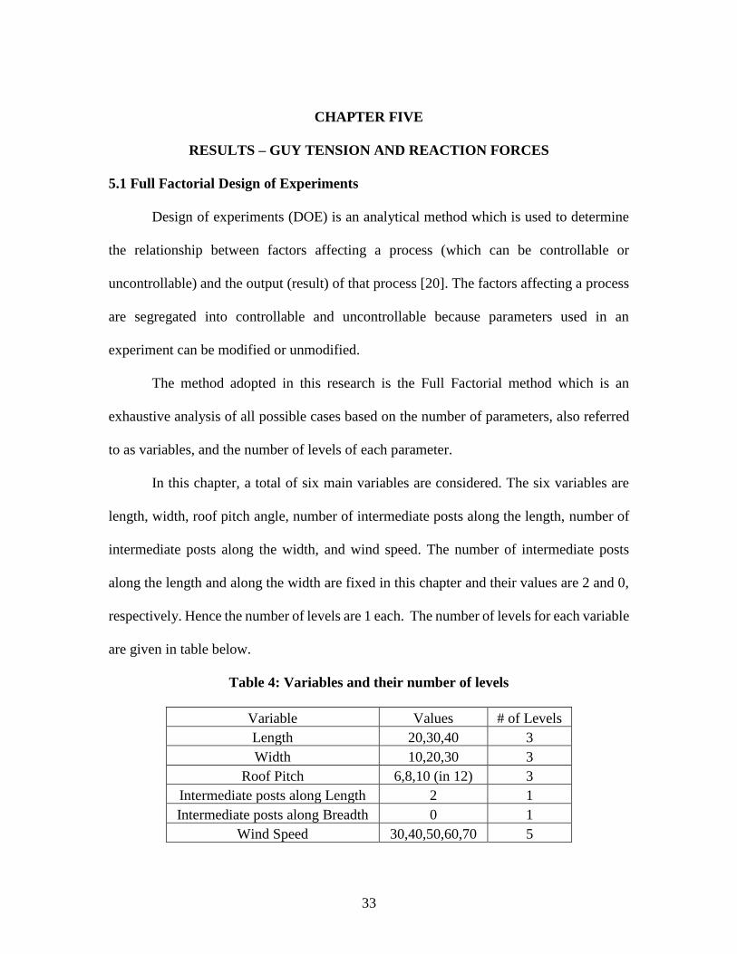
5.1 Full Factorial Design of Experiments
Design of experiments (DOE) is an analytical method which is used to determine
the relationship between factors affecting a process (which can be controllable or
uncontrollable) and the output (result) of that process [20]. The factors affecting a process
are segregated into controllable and uncontrollable because parameters used in an
experiment can be modified or unmodified.
The method adopted in this research is the Full Factorial method which is an
exhaustive analysis of all possible cases based on the number of parameters, also referred
to as variables, and the number of levels of each parameter.
In this chapter, a total of six main variables are considered. The six variables are
length, width, roof pitch angle, number of intermediate posts along the length, number of
intermediate posts along the width, and wind speed. The number of intermediate posts
along the length and along the width are fixed in this chapter and their values are 2 and 0,
respectively. Hence the number of levels are 1 each. The number of levels for each variable
are given in table below.
Table 4: Variables and their number of levels
Variable Values # of Levels
Length 20,30,40 3
Width 10,20,30 3
Roof Pitch 6,8,10 (in 12) 3
Intermediate posts along Length 2 1
Intermediate posts along Breadth 0 1
Wind Speed 30,40,50,60,70 5
34
After finding the number of levels for each variable, the number of levels are multiplied
to estimate the total number of cases.
3 x 3 x 3 x 5 x 1 x 1 = 135 cases
To calculate the total time required to calculate all the wind load combinations, it
is multiplied by 8.
135 x 8 = 1080 cases
The time taken to calculate the one case out of 1080 cases is roughly 5 minutes.
Hence to obtain the total time for calculating 1080 cases, it is
1080 cases x 5 minutes = 90 hours
Thus, it takes approximately 90 hours to calculate the ballast weights for 1080
cases. Since this method showed that conducting experiments was feasible in a reasonable
time, the Full Factorial method was adopted to determine the variable configuration cases.
The weight of the ballast is directly dependent upon the wind loads applied on the tent
structure. One of the important parameters which influences the weight of the ballast is the
surface area of the tent. Intuitively, the bigger the tent, the greater the ballast. However,
this statement is not always true because of the counter-effect of other parameters such as
the number of intermediate posts. For a given length of the tent, the distance between
intermediate posts can vary between 10 and 20 feet depending on the length of the tent.
The smaller the distance between posts, the more intermediate posts, and therefore the more
individual ballasts. Increasing the number of intermediate posts results in decreasing the
weight of individual ballasts. Therefore, the length and the number of intermediate posts
have opposite effects on individual ballast weights and may cancel each other.
35
5.2 Non-Uniform Distribution of guy tension
In this section, the ballast weight is decided based on three groups of guys instead
of having a unique ballast weight for each guy. The pre-tension applied to the guys was
assumed to be uniform before the application of wind loads. After the wind loads were
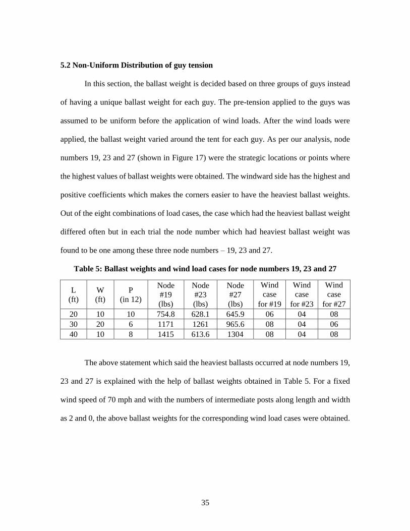
applied, the ballast weight varied around the tent for each guy. As per our analysis, node
numbers 19, 23 and 27 (shown in Figure 17) were the strategic locations or points where
the highest values of ballast weights were obtained. The windward side has the highest and
positive coefficients which makes the corners easier to have the heaviest ballast weights.
Out of the eight combinations of load cases, the case which had the heaviest ballast weight
differed often but in each trial the node number which had heaviest ballast weight was
found to be one among these three node numbers – 19, 23 and 27.
Table 5: Ballast weights and wind load cases for node numbers 19, 23 and 27
L
(ft)
W
(ft)
P
(in 12)
Node
#19
(lbs)
Node
#23
(lbs)
Node
#27
(lbs)
Wind
case
Wind
case
Wind
case
for #19 for #23 for #27
20 10 10 754.8 628.1 645.9 06 04 08
30 20 6 1171 1261 965.6 08 04 06
40 10 8 1415 613.6 1304 08 04 08
The above statement which said the heaviest ballasts occurred at node numbers 19,
23 and 27 is explained with the help of ballast weights obtained in Table 5. For a fixed
wind speed of 70 mph and with the numbers of intermediate posts along length and width
as 2 and 0, the above ballast weights for the corresponding wind load cases were obtained.
36
Figure 17: Tent with ‘nodes’ marked by numbers
The heaviest ballast occurred either at node number 19 or node number 23 as shown
in rows 1 and 2 of Table 5. For a few trials, the ballast weight at node number 27 was
higher than the ballast weight at node number 23 as shown in row 3 of Table 5 and the
reason this happened was because of the forces acting on node 15 was greater than the
forces acting on node 2 in the transversal direction due to large pressure coefficients (Cp)
and large tributary width of the forces acting on node 15.
The heaviest ballasts are needed at the node numbers 19, 23 and 27. This represents
the corner of the tent. If the wind is to blow on either longitudinal or transversal direction
on any side of the wall, the tent will have the corners as the critical areas which have the
heaviest ballast weights by symmetry. This leads to three groups of guys which are
explained by color code in Figure 13. The three types of guys based on position are – guys
37
at corners in longitudinal direction (shown in green), guys at corners in transversal
direction (shown in red) and intermediate guys between corners in transversal direction
(shown in blue). Thus, a tent with this configuration will have three groups of ballast
weights with each ballast weight corresponding to each type of guy based on position.
In the following sections, the effect of each individual parameter on the maximum
ballast weight is studied. The effects of two simultaneous parameters is then considered to
show the mutual effect on ballast weights. For instance, the length of the tent is considered
while maintaining all other parameters constant. Then, the length of the tent and the number
of intermediate posts are considered simultaneously.
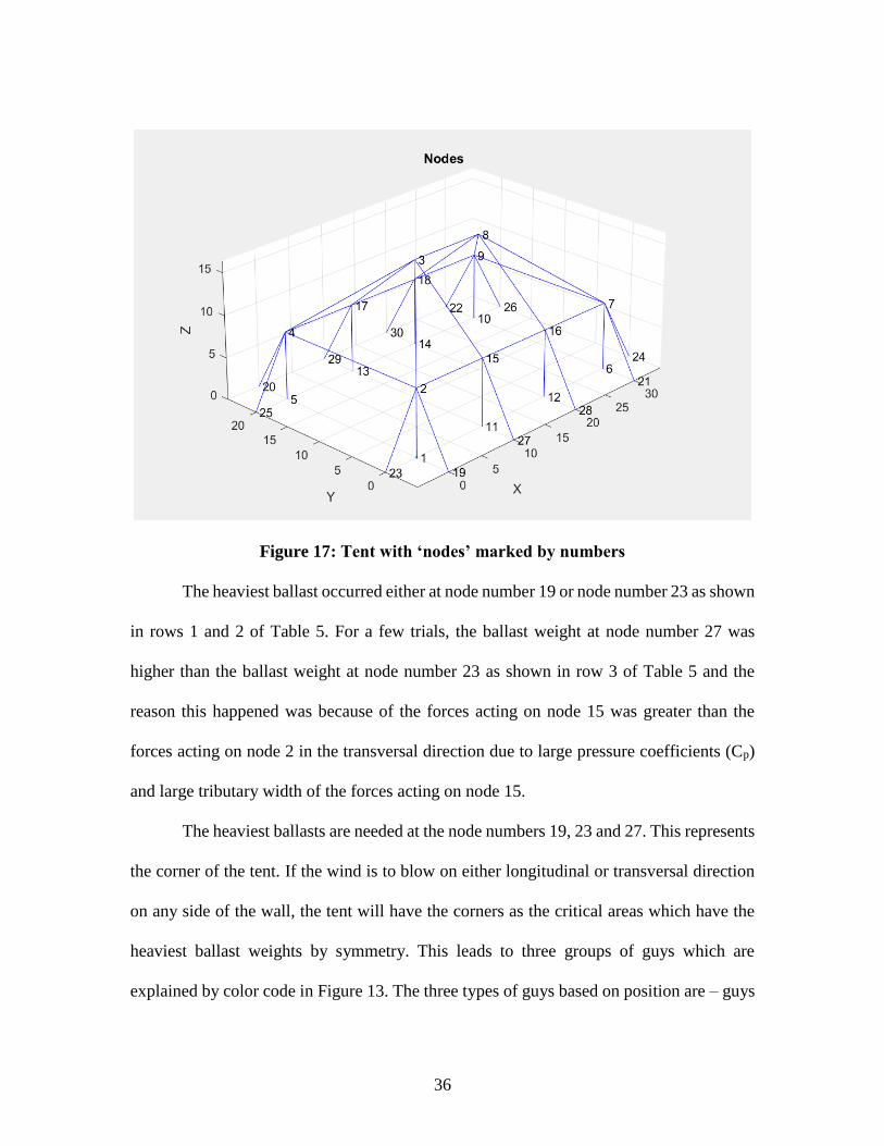
5.3 Effect of Tent Length
The first parameter considered was the length of the tent. The length of the tent
examined were 20 ft, 30 ft and 40 ft. The rest of the parameters, including the number of
intermediate posts, were kept constant and those considered are listed in Table 6.
Table 6: Parameter values used for different values of length
Length of tent Varies
Width of tent 10 ft
Pitch of roof 6 in 12
Intermediate posts along length 2
Intermediate posts along width 0
Speed of wind 70 mph
The pre-tension was restricted to 300 lbf for all the guys connecting the frame and
ballasts. As shown in Figure 18, the maximum ballast weight increases proportionally with
the length. The maximum ballast weights were found to be 673.7 lbs, 1001 lbs and 1335
lbs for lengths 20 ft, 30 ft and 40 ft respectively.
38
Figure 18: Graph showing length of tent (ft)(X-axis) vs. ballast weights (lbs)(Y-axis)
5.4 Effect of Tent Width
The second parameter considered was the width of the tent. The width of the tent
examined were 10 ft, 20 ft and 30 ft. The rest of the parameters were kept constant and
those considered are listed in Table 7.
Table 7: Parameter values used for different values of width
Length of tent 40 ft
Width of tent Varies
Pitch of roof 6 in 12
Intermediate posts along length 2
Intermediate posts along width 0
Speed of wind 70 mph
The pre-tension was restricted to 300 lbf for all the guys connecting the frame and
ballasts. As envisioned, the ballast weight increases in the same way as the parameter value
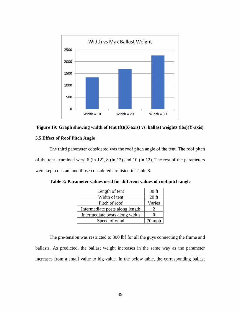
increases for tent width. In the below Figure 19, the corresponding ballast weights for
widths 10 ft, 20 ft and 30 ft were found to be 1335 lbs, 1692 lbs and 2264 lbs.
0
200
400
600
800
1000
1200
1400
1600
Length = 20 Length = 30 Length = 40
Length vs Max Ballast Weight
39
Figure 19: Graph showing width of tent (ft)(X-axis) vs. ballast weights (lbs)(Y-axis)
5.5 Effect of Roof Pitch Angle
The third parameter considered was the roof pitch angle of the tent. The roof pitch
of the tent examined were 6 (in 12), 8 (in 12) and 10 (in 12). The rest of the parameters
were kept constant and those considered are listed in Table 8.
Table 8: Parameter values used for different values of roof pitch angle
Length of tent 30 ft
Width of tent 20 ft
Pitch of roof Varies
Intermediate posts along length 2
Intermediate posts along width 0
Speed of wind 70 mph
The pre-tension was restricted to 300 lbf for all the guys connecting the frame and
ballasts. As predicted, the ballast weight increases in the same way as the parameter
increases from a small value to big value. In the below table, the corresponding ballast
0
500
1000
1500
2000
2500
Width = 10 Width = 20 Width = 30
Width vs Max Ballast Weight
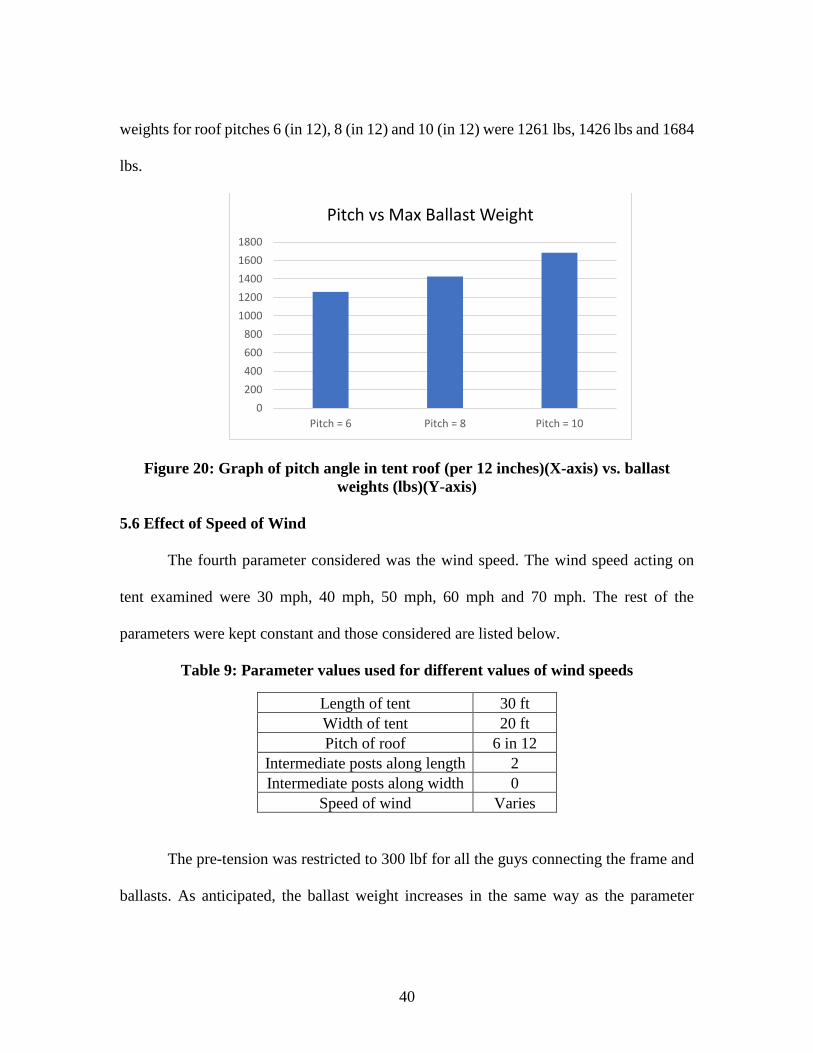
40
weights for roof pitches 6 (in 12), 8 (in 12) and 10 (in 12) were 1261 lbs, 1426 lbs and 1684
lbs.
Figure 20: Graph of pitch angle in tent roof (per 12 inches)(X-axis) vs. ballast
weights (lbs)(Y-axis)
5.6 Effect of Speed of Wind
The fourth parameter considered was the wind speed. The wind speed acting on
tent examined were 30 mph, 40 mph, 50 mph, 60 mph and 70 mph. The rest of the
parameters were kept constant and those considered are listed below.
Table 9: Parameter values used for different values of wind speeds
Length of tent 30 ft
Width of tent 20 ft
Pitch of roof 6 in 12
Intermediate posts along length 2
Intermediate posts along width 0
Speed of wind Varies
The pre-tension was restricted to 300 lbf for all the guys connecting the frame and
ballasts. As anticipated, the ballast weight increases in the same way as the parameter
0
200
400
600
800
1000
1200
1400
1600
1800
Pitch = 6 Pitch = 8 Pitch = 10
Pitch vs Max Ballast Weight
41
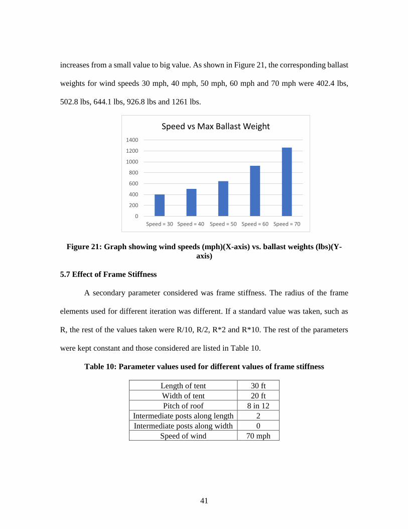
increases from a small value to big value. As shown in Figure 21, the corresponding ballast
weights for wind speeds 30 mph, 40 mph, 50 mph, 60 mph and 70 mph were 402.4 lbs,
502.8 lbs, 644.1 lbs, 926.8 lbs and 1261 lbs.
Figure 21: Graph showing wind speeds (mph)(X-axis) vs. ballast weights (lbs)(Y-
axis)
5.7 Effect of Frame Stiffness
A secondary parameter considered was frame stiffness. The radius of the frame
elements used for different iteration was different. If a standard value was taken, such as
R, the rest of the values taken were R/10, R/2, R*2 and R*10. The rest of the parameters
were kept constant and those considered are listed in Table 10.
Table 10: Parameter values used for different values of frame stiffness
Length of tent 30 ft
Width of tent 20 ft
Pitch of roof 8 in 12
Intermediate posts along length 2
Intermediate posts along width 0
Speed of wind 70 mph
0
200
400
600
800
1000
1200
1400
Speed = 30 Speed = 40 Speed = 50 Speed = 60 Speed = 70
Speed vs Max Ballast Weight
42
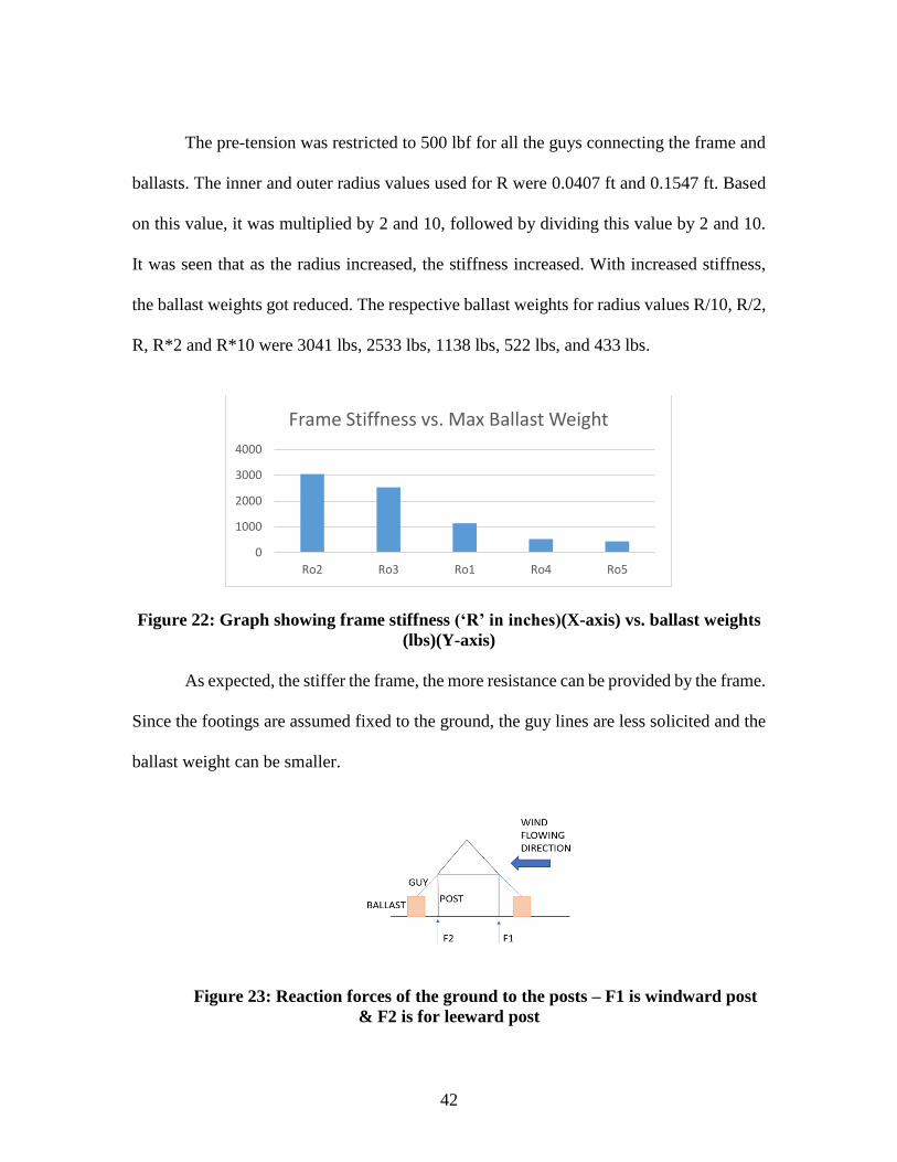
The pre-tension was restricted to 500 lbf for all the guys connecting the frame and
ballasts. The inner and outer radius values used for R were 0.0407 ft and 0.1547 ft. Based
on this value, it was multiplied by 2 and 10, followed by dividing this value by 2 and 10.
It was seen that as the radius increased, the stiffness increased. With increased stiffness,
the ballast weights got reduced. The respective ballast weights for radius values R/10, R/2,
R, R*2 and R*10 were 3041 lbs, 2533 lbs, 1138 lbs, 522 lbs, and 433 lbs.
Figure 22: Graph showing frame stiffness (‘R’ in inches)(X-axis) vs. ballast weights
(lbs)(Y-axis)
As expected, the stiffer the frame, the more resistance can be provided by the frame.
Since the footings are assumed fixed to the ground, the guy lines are less solicited and the
ballast weight can be smaller.
Figure 23: Reaction forces of the ground to the posts – F1 is windward post
& F2 is for leeward post
0
1000
2000
3000
4000
Ro2 Ro3 Ro1 Ro4 Ro5
Frame Stiffness vs. Max Ballast Weight
43
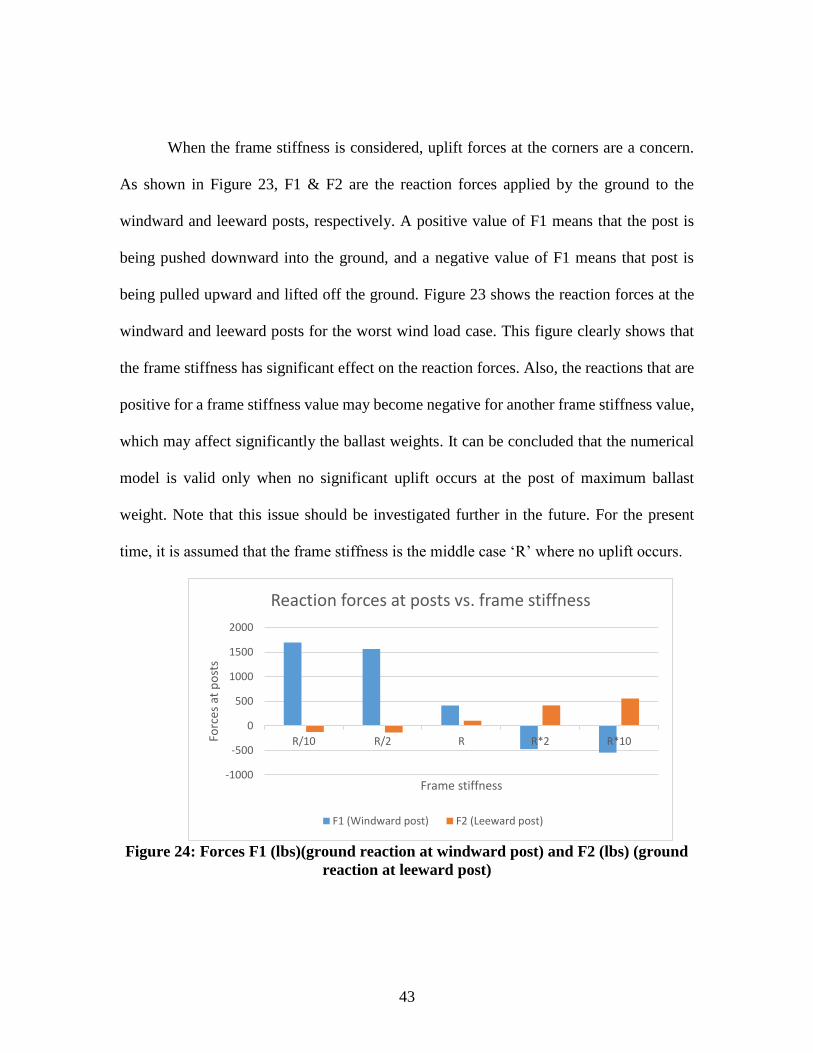
When the frame stiffness is considered, uplift forces at the corners are a concern.
As shown in Figure 23, F1 & F2 are the reaction forces applied by the ground to the
windward and leeward posts, respectively. A positive value of F1 means that the post is
being pushed downward into the ground, and a negative value of F1 means that post is
being pulled upward and lifted off the ground. Figure 23 shows the reaction forces at the
windward and leeward posts for the worst wind load case. This figure clearly shows that
the frame stiffness has significant effect on the reaction forces. Also, the reactions that are
positive for a frame stiffness value may become negative for another frame stiffness value,
which may affect significantly the ballast weights. It can be concluded that the numerical
model is valid only when no significant uplift occurs at the post of maximum ballast
weight. Note that this issue should be investigated further in the future. For the present
time, it is assumed that the frame stiffness is the middle case ‘R’ where no uplift occurs.
Figure 24: Forces F1 (lbs)(ground reaction at windward post) and F2 (lbs) (ground
reaction at leeward post)
-1000
-500
0
500
1000
1500
2000
R/10 R/2 R R*2 R*10Forc
es a
t p
ost
s
Frame stiffness
Reaction forces at posts vs. frame stiffness
F1 (Windward post) F2 (Leeward post)
44
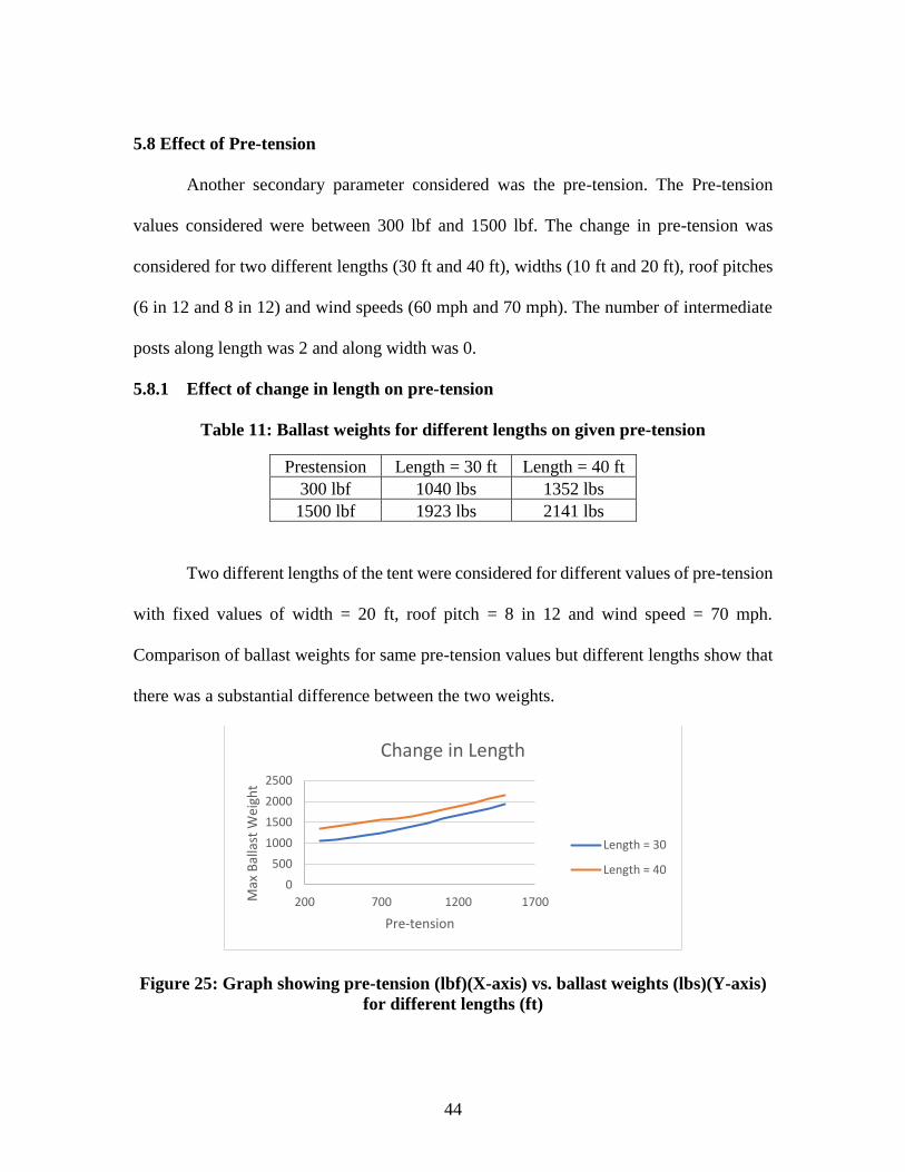
5.8 Effect of Pre-tension
Another secondary parameter considered was the pre-tension. The Pre-tension
values considered were between 300 lbf and 1500 lbf. The change in pre-tension was
considered for two different lengths (30 ft and 40 ft), widths (10 ft and 20 ft), roof pitches
(6 in 12 and 8 in 12) and wind speeds (60 mph and 70 mph). The number of intermediate
posts along length was 2 and along width was 0.
5.8.1 Effect of change in length on pre-tension
Table 11: Ballast weights for different lengths on given pre-tension
Prestension Length = 30 ft Length = 40 ft
300 lbf 1040 lbs 1352 lbs
1500 lbf 1923 lbs 2141 lbs
Two different lengths of the tent were considered for different values of pre-tension
with fixed values of width = 20 ft, roof pitch = 8 in 12 and wind speed = 70 mph.
Comparison of ballast weights for same pre-tension values but different lengths show that
there was a substantial difference between the two weights.
Figure 25: Graph showing pre-tension (lbf)(X-axis) vs. ballast weights (lbs)(Y-axis)
for different lengths (ft)
0
500
1000
1500
2000
2500
200 700 1200 1700Max
Bal
last
Wei
ght
Pre-tension
Change in Length
Length = 30
Length = 40
45
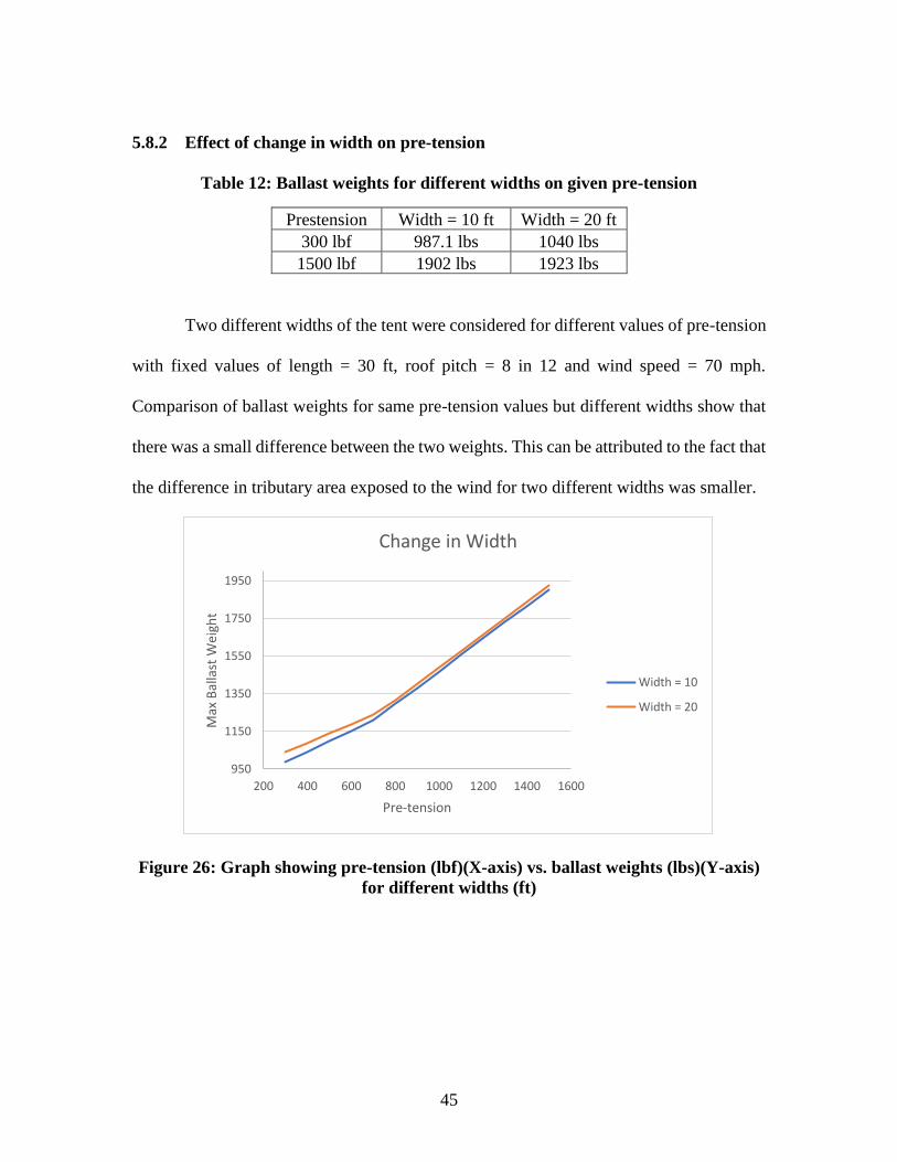
5.8.2 Effect of change in width on pre-tension
Table 12: Ballast weights for different widths on given pre-tension
Prestension Width = 10 ft Width = 20 ft
300 lbf 987.1 lbs 1040 lbs
1500 lbf 1902 lbs 1923 lbs
Two different widths of the tent were considered for different values of pre-tension
with fixed values of length = 30 ft, roof pitch = 8 in 12 and wind speed = 70 mph.
Comparison of ballast weights for same pre-tension values but different widths show that
there was a small difference between the two weights. This can be attributed to the fact that
the difference in tributary area exposed to the wind for two different widths was smaller.
Figure 26: Graph showing pre-tension (lbf)(X-axis) vs. ballast weights (lbs)(Y-axis)
for different widths (ft)
950
1150
1350
1550
1750
1950
200 400 600 800 1000 1200 1400 1600
Max
Bal
last
Wei
ght
Pre-tension
Change in Width
Width = 10
Width = 20
46
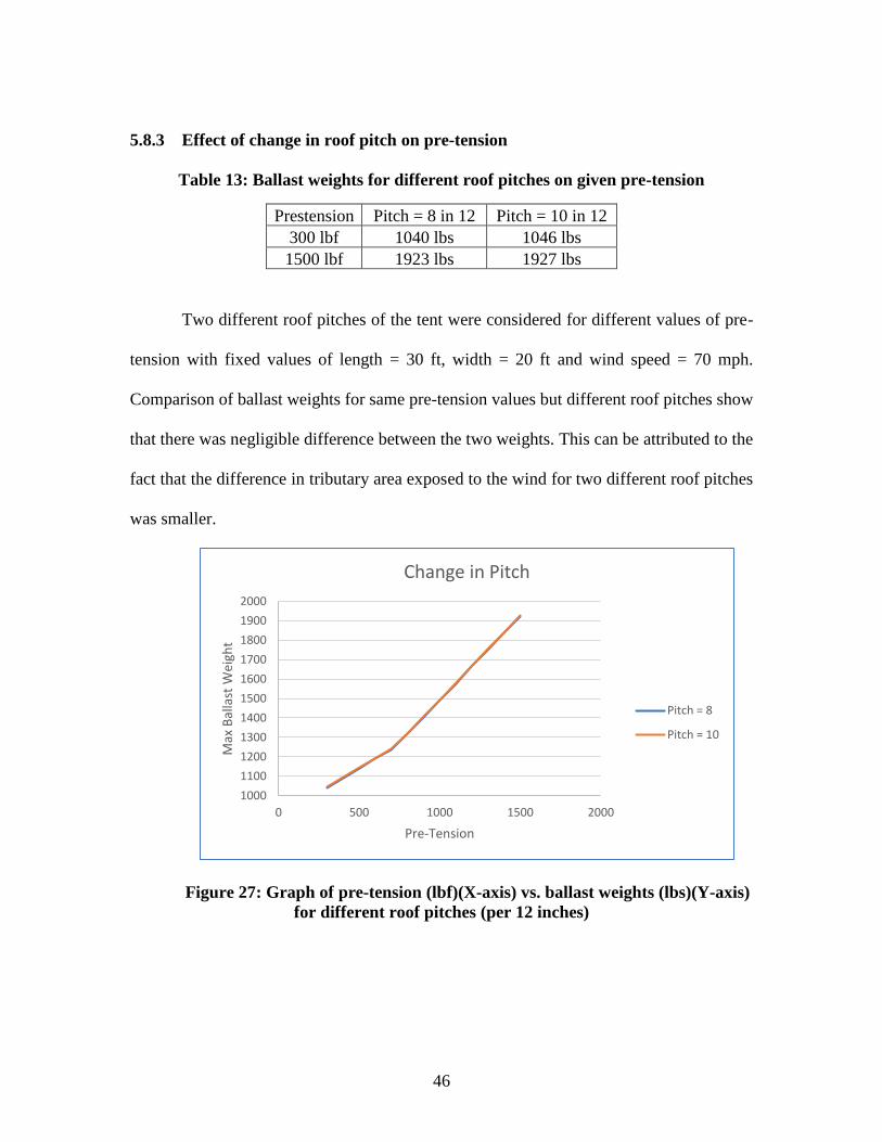
5.8.3 Effect of change in roof pitch on pre-tension
Table 13: Ballast weights for different roof pitches on given pre-tension
Prestension Pitch = 8 in 12 Pitch = 10 in 12
300 lbf 1040 lbs 1046 lbs
1500 lbf 1923 lbs 1927 lbs
Two different roof pitches of the tent were considered for different values of pre-
tension with fixed values of length = 30 ft, width = 20 ft and wind speed = 70 mph.
Comparison of ballast weights for same pre-tension values but different roof pitches show
that there was negligible difference between the two weights. This can be attributed to the
fact that the difference in tributary area exposed to the wind for two different roof pitches
was smaller.
Figure 27: Graph of pre-tension (lbf)(X-axis) vs. ballast weights (lbs)(Y-axis)
for different roof pitches (per 12 inches)
1000
1100
1200
1300
1400
1500
1600
1700
1800
1900
2000
0 500 1000 1500 2000
Max
Bal
last
Wei
ght
Pre-Tension
Change in Pitch
Pitch = 8
Pitch = 10

47
5.8.4 Effect of change in wind speed on pre-tension
Table 14: Ballast weights for different wind speeds on given pre-tension
Pre-tension Speed = 60 mph Speed = 70 mph
300 lbf 803.1 lbs 1040 lbs
1500 lbf 1758 lbs 1923 lbs
Two different wind speeds were considered for different values of pre-tension with
fixed values of length = 30 ft, width = 20 ft and roof pitch = 8 in 12. Comparison of ballast
weights for the same pre-tension values but different wind speeds show that there was a
substantial difference between the two weights. Hence the faster the wind, heavier the
ballast weight.
Figure 28: Graph showing pre-tension (lbf)(X-axis) vs. ballast weights (lbs)(Y-axis)
for different wind speeds (mph)
0
500
1000
1500
2000
2500
200 400 600 800 1000 1200 1400 1600
Max
Bal
last
Wei
ght
Pre-tension
Change in Speed
Speed = 60
Speed = 70
48
CHAPTER SIX
EXPERIMENTAL MEASUREMENTS
6.1 Experimental Setup
Experiments were conducted to determine the load factor. The load factor depends
on the type of ballast and ground surface. The type of ballasts which can be used are plastic
barrels filled with water or concrete, steel drum filled with concrete, and concrete blocks.
The ground surfaces which are used usually are asphalt, smooth concrete, rough concrete,
grass, dirt and gravel. Each ground surface can be either wet or dry. Surface modifiers like
steel plates and polymeric pads can be used between the ballast and ground surface to
potentially increase the overall friction coefficient.
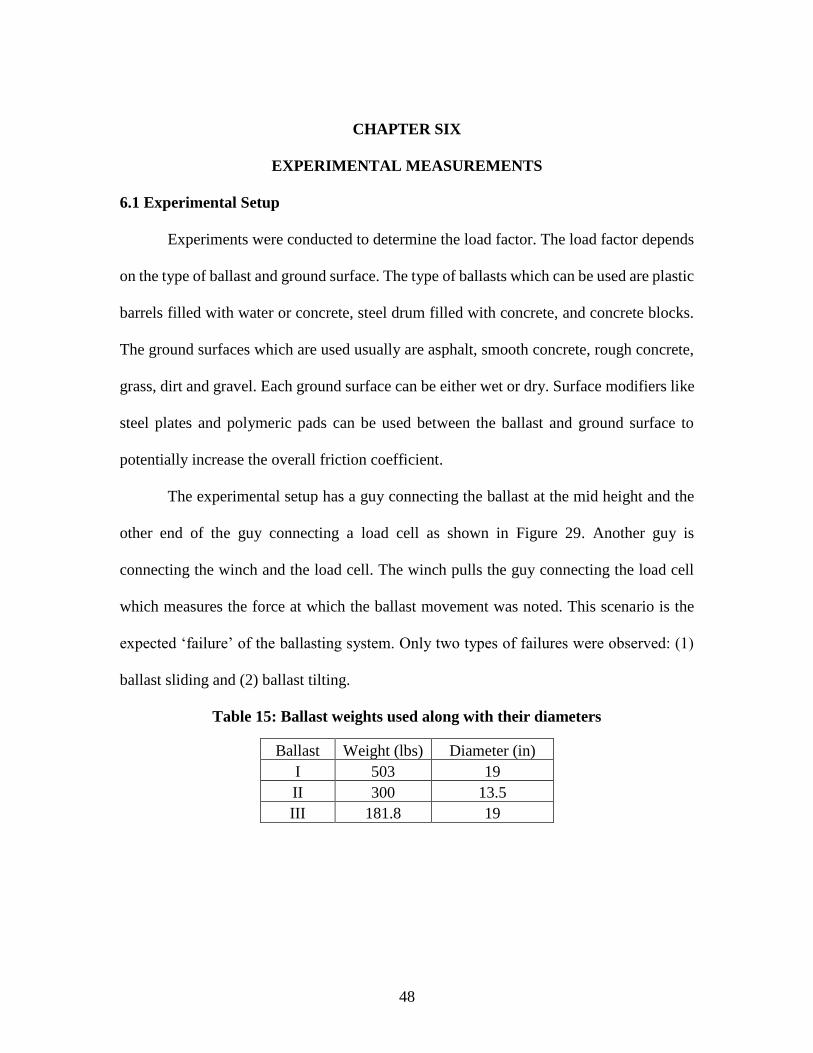
The experimental setup has a guy connecting the ballast at the mid height and the
other end of the guy connecting a load cell as shown in Figure 29. Another guy is
connecting the winch and the load cell. The winch pulls the guy connecting the load cell
which measures the force at which the ballast movement was noted. This scenario is the
expected ‘failure’ of the ballasting system. Only two types of failures were observed: (1)
ballast sliding and (2) ballast tilting.
Table 15: Ballast weights used along with their diameters
Ballast Weight (lbs) Diameter (in)
I 503 19
II 300 13.5
III 181.8 19
49
Figure 29: Experimental setup
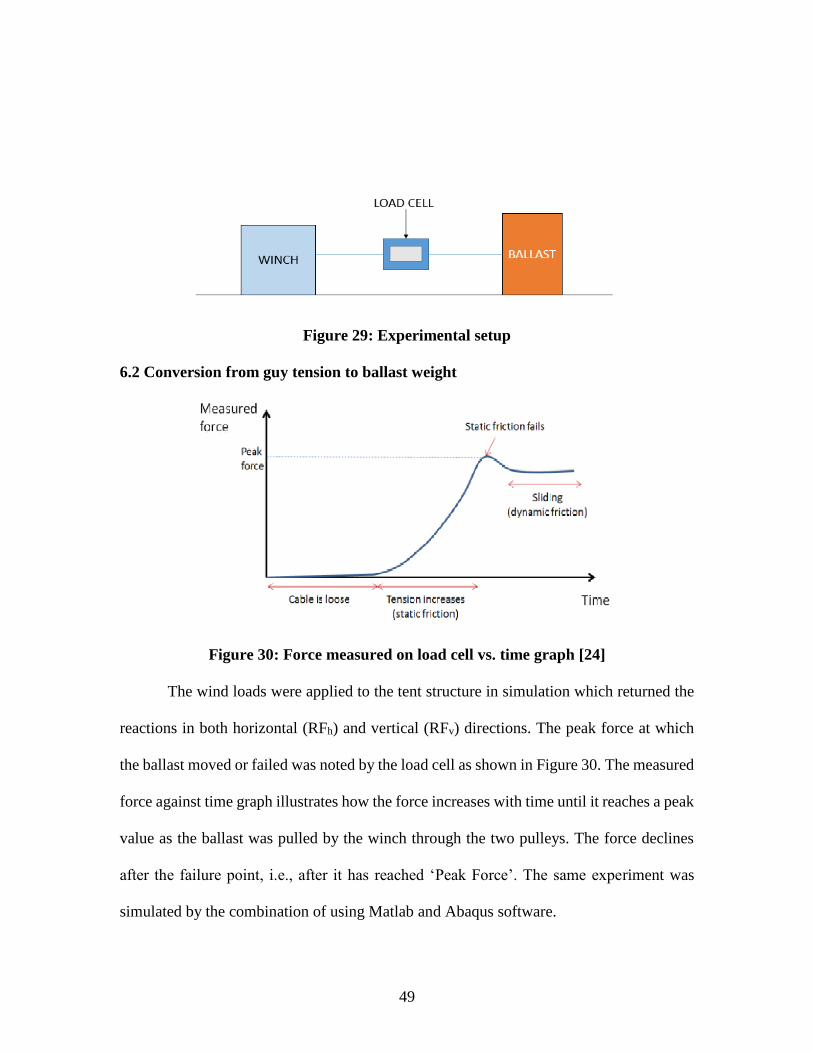
6.2 Conversion from guy tension to ballast weight
Figure 30: Force measured on load cell vs. time graph [24]
The wind loads were applied to the tent structure in simulation which returned the
reactions in both horizontal (RFh) and vertical (RFv) directions. The peak force at which
the ballast moved or failed was noted by the load cell as shown in Figure 30. The measured
force against time graph illustrates how the force increases with time until it reaches a peak
value as the ballast was pulled by the winch through the two pulleys. The force declines
after the failure point, i.e., after it has reached ‘Peak Force’. The same experiment was
simulated by the combination of using Matlab and Abaqus software.
50
The reaction in vertical direction (RFv) is considered as it is, whereas the reaction
in horizontal direction (RFh) was divided by the friction coefficient (µ) to get the equivalent
force in the vertical direction (RFh/µ). The ballast weight ‘W’ value must always be higher
than either of the reaction forces RFv or RFh/µ in order to ensure stability of the post.
6.3 Determination of Load factors
The experiment was carried out on a dry concrete condition. The aim of this
experiment was to determine which ballast was suitable for our future experiments based
on the consistency of its friction coefficients or load factors. Five trials were done for two
conditions – (1) with one pulley and (2) with two pulleys. Two pulleys were used to record
smooth movement of ballasts under sliding failure. The force at which ballast started to
slide or tilt was noted. The average force from all five trials were taken and was divided by
the ballast weight to obtain friction coefficient. Tables 16 and 17 show that irrespective of
using one or two pulleys, the friction coefficients obtained are the same for Ballast type I
– the heaviest among the three tested ballasts. A friction coefficient value of 0.23 was
recorded for Ballast I.
Table 16: Friction coefficients for experiments conducted with one pulley
Experiment with one pulley
Ballast
Type Trial 1 Trial 2 Trial 3 Trial 4 Trial 5
Average
(lbs)
Friction
coefficient
I 109.2 117.05 120 113.3 112.15 114.34 0.23
II 85.5 86.4 81.35 84.05 82.1 83.88 0.28
II 54.25 55.95 57.4 52.15 58.7 55.69 0.31
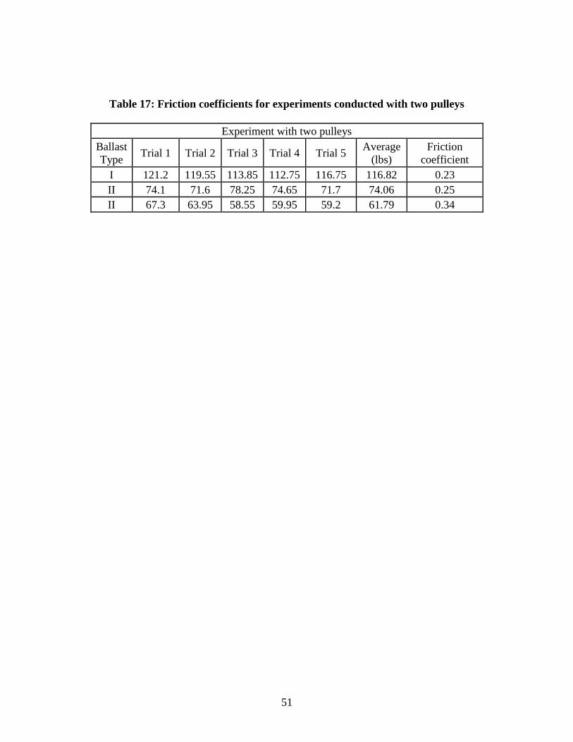
51
Table 17: Friction coefficients for experiments conducted with two pulleys
Experiment with two pulleys
Ballast
Type Trial 1 Trial 2 Trial 3 Trial 4 Trial 5
Average
(lbs)
Friction
coefficient
I 121.2 119.55 113.85 112.75 116.75 116.82 0.23
II 74.1 71.6 78.25 74.65 71.7 74.06 0.25
II 67.3 63.95 58.55 59.95 59.2 61.79 0.34
52
CHAPTER SEVEN
CONCLUSION AND FUTURE WORK
The main aim of this project was to provide International Fabrics Association
Industrial (IFAI) with the minimum ballast weight values that can safely hold various tents
to the ground for the wind loads prescribed by code. Using Finite Element Analysis, Matlab
scripts were created to model tents and return ballast weight values for a tent with a given
configuration, type of ballast and surface region on which the tent was placed.
A Full Factorial Design of Experiments approach was used. The effect of the guy’s
pre-tension, wind speed for a region, tent’s length, width and roof pitch angle on the ballast
weight values were observed. It was found from this experiments that the higher the values
of wind speed, guys’ pre-tension, length, width, and roof pitch angle, the heavier the ballast
weights. All the experiments in Matlab were carried out only in partially enclosed condition
using Main Wind Force Resisting System (MWFRS) method.
This project has given way for future work to take other factors into account for
determining and optimizing the values of ballast weights. The limitations of the method
should be resolved. In particular, the ability to include the ability of the footings to lift
should be included in conjunction with the application of pre-tension in guy lines.
Additional research subjects should include studying the effect of frame stiffness and guy
stiffness on ballast weight values, as well as the effect of enclosed and open conditions of
walls on ballast weight values and finally, all the effects should be studied for Components
and Cladding (C&C) method instead of MWFRS method.
53
REFERENCES
[1] “Ballast”, Ballast, 14 Mar. 2016.
https://en.wikipedia.org/wiki/Ballast
[2] "Company Overview", Industrial Fabrics Association International, 14 Mar. 2016.
www.ifai.com/about/
[3] Mohammadi, Jamshid, and Amir Zamani Heydari. “Seismic and Wind Load
considerations for Temporary Structures.” Practice Periodical on Structural Design and
Construction, vol. 13, no. 3, 2008, pp. 128–134.
[4] Bolduc, William T. “When the Roof Collapses.” Structures Congress 2011, 2011, pp.
1827-1838.
[5] Gorlin, William B. “Wind Loads for Temporary Structures: Making the Case for
Industrywide Standards.” Journal of Architectural Engineering, vol. 15, no. 2, 2009, pp.
35–36.
[6] McAlpine, George. “Caution! FEA in Use.” Pipelines 2013, Nov. 2013, pp. 556 - 565.
[7] Mu, Bin, et al. “FEA of Complex Bridge System with FRP Composite Deck.” Journal
of Composites for Construction, vol. 10, no. 1, 2006, pp. 79–86.
[8] Bail, Justin L. “Non-Destructive Investigation & FEA Correlation on an Aircraft
Sandwich Composite Structure.” Earth and Space Conference 2008: Proceedings of the
11th Aerospace Division International Conference on Engineering, Science, Construction,
and Operations in Challenging Environments, vol. 323, Apr. 2008.
54
[9] Lu, S. C., et al. “Integration of CAD and FEA for Concurrent Engineering Design of
Sheet Stamping.” Journal of Manufacturing Science and Engineering, vol. 118, no. 3, 1996,
pp. 310–317.
[10] Dinh, T.D., et al. “A Study of Tension Fabric Membrane Structures under in-Plane
Loading: Nonlinear Finite Element Analysis and Validation.” Composite Structures, vol.
128, 2015, pp. 10–20.
[11] Zhao, Jiaxin. “Computer Application in Solving Statically Determinate Truss
Problems Using FEA and Matlab.” Computer Applications in Engineering Education, vol.
17, no. 4, 2009, pp. 363–371.
[12] Pike, M. “Introducing Finite Element Analysis in Statics,” Proceedings of the 2001
American Society for Engineering Education Annual Conference & Exposition, 2001.
[13] St.Pierre, L.M., et al. Wind Loads on Houses: A Wind Tunnel Study. Institute for
Catastrophic Loss Reduction Research Paper Series, 2003.
[14] Stathopoulos, Theodore, et al. “Wind Shielding Effects of Trees on Low
Buildings.” Building and Environment, vol. 29, no. 2, 1994, pp. 141–150.
[15] Wang, Ronghui, et al. “Model Test and Numerical Analysis of a Special Joint for a
Truss Bridge.” Journal of Constructional Steel Research, vol. 65, no. 6, 2009, pp. 1261–
1268.
[16] Kurowski, P. "Good solid modeling, bad FEA." Machine Design International, vol.
68, no. 21, Nov. 1996, pp. 67–72.
[17] He, Lin, et al. “Parametric Modeling and Stability Analysis of Temporary
Grandstand.” Applied Mechanics and Materials, vol. 578-579, 2014, pp. 907–916.

55
[18] American Society of Civil Engineers. Minimum Design Loads for Buildings and Other
Structures, Standard ASCE/SEI 7-10. 2013.
[19] Hinton, E., and D. R. J. Owen. An Introduction to Finite-Element Computations.
Pineridge Pr., 1985.
[20] "Design of Experiments – A Primer", iSixSigma, 6 Feb. 2016.
https://www.isixsigma.com/tools-templates/design-of-experiments-doe/design-
experiments-%E2%90%93-primer/
[21] "Overview", Matlab, 6 Feb. 2016.
https://www.mathworks.com/products/matlab.html?s_tid=hp_products_matlab
[22] "Abaqus Unified FEA", Abaqus, 6 Feb. 2016.
https://www.3ds.com/products-services/simulia/products/abaqus/abaquscae/
[23] "About ASCE", ASCE, 6 Feb. 2016.
https://www.asce.org/about_asce/
[24] Summers J., Blouin V., IFAI 2011: Testing and Performance Analysis of Tent Ballast,
Report submitted to Industrial Fabrics Association International, Clemson University,
April 2012.