Embed Size (px)
Citation preview

Advances in Computational Design, Vol. 1, No. 3 (2016) 253-264
DOI: http://dx.doi.org/10.12989/acd.2016.1.3.253 253
Copyright © 2016 Techno-Press, Ltd.
http://www.techno-press.com/journals/acd&subpage=7 ISSN: 2383-8477 (Print), 2466-0523 (Online)
Determination of strut efficiency factor for concrete deep beams with and without fibre
Sandeep M.S., Praveen Nagarajana, A.P. Shashikalab and Shehin A. Habeebc
Department of Civil Engineering, NIT Calicut
(Received January 10, 2016, Revised June 25, 2016, Accepted June 28, 2016)
Abstract. Based on the variation of strain along the cross section, any region in a structural member can be
classified into two regions namely, Bernoulli’s region (B-region) and Disturbed region (D-region). Since the
variation of strain along the cross section for a B-region is linear, well-developed theories are available for
their analysis and design. On the other hand, the design of D-region is carried out based on thumb rules and
past experience due to the presence of nonlinear strain distribution. Strut-and-Tie method is a novel
approach that can be used for the analysis and design of both B-region as well as D-region with equal
importance. The strut efficiency factor (βs) is needed for the design and analysis of concrete members using
Strut and Tie method. In this paper, equations for finding βs for bottle shaped struts in concrete deep beams
(a D-region) with and without steel fibres are developed. The effects of transverse reinforcement on βs are
also considered. Numerical studies using commercially available finite element software along with limited
amount of experimental studies were used to find βs.
Keywords: strut; efficiency factor; strut-and-tie; STM; fibre reinforced concrete; SFRC; ANSYS;
nonlinear analysis of concrete; nonlinear finite element analysis of reinforced concrete
1. Introduction
Any region in a structure can be classified into two regions namely, Bernoulli’s region (B-
Region) and Disturbed region (D-Region) based on the variation of strain across the cross section.
The well-developed flexure theories can be used for analysis and design B-Regions. On the
contrary, due to the presence of nonlinear strain distribution the analysis and design of D-region is
carried out based on thumb rules and past experience. Since both the B-region as well as D-region
of a structure are of equal importance, a method that can be used for designing both the regions
with equal importance is needed. Strut-and-Tie method is an alternative approach that can be used
for the analysis and design of a structure providing equal importance for B-region and D-region.
This method has found place in many of the international codes like American code ACI-318-14,
Canadian code CSA-A23.3-14, Australian code AS 3600-2009, Euro code EC2:2004, New
Corresponding author, Research Scholar, E-mail: [email protected] aAssociate Professor, E-mail: [email protected]
bProfessor
cM-Tech student

Sandeep M.S., Praveen Nagarajan, A.P. Shashikala and Shehin A. Habeeb
Fig. 1 STM for deep beam with central point load
Zealand code NZE 3101-1-2006, etc. A strut-and-tie model (STM) mainly consist of three parts
which are compression struts, tension ties and nodes. The struts are members of a strut-and-tie
model that carry compression force and the ties are members that carry tensile force. The
intersection portion of members of a strut-and-tie model are termed as nodes. Fig. 1 illustrates the
different components of a STM for a deep beam.
The accurate estimation of the strength of concrete strut is the key to the effectiveness of strut-
and-tie method. The major type of strut that are commonly used are prismatic or bottle-shaped,
depending on their positions within the structural element. The cross sectional area of a prismatic
strut is uniform over its entire length whereas in a bottle-shaped strut, the cross-sectional area
increases towards the mid-length with the strut assuming a bottle- shaped profile owing to lateral
spreading of the compressive stress field. Even though reasonable amount of research has been
carried out to establish the allowable strength of a strut for normal concrete, the work done on the
allowable strength of fibre reinforced concrete is less. STM procedures were introduced in the
2002 version of American Concrete Institute (ACI) 318 as ‘Appendix A: Strut-and-tie Model’s,
which underwent minor changes in the later versions. In chapter 23 of ACI 318-14, the nominal
compressive strength of a strut is given by Eq. (1)
Fns = f ce Acs (1)
[Eq. 23.4.1a, ACI 318-14 chapter 23]
Where Fns is nominal compressive strength of a strut without longitudinal reinforcement, Acs is
the lesser of the cross-sectional areas at the two ends of a strut, fce is effective compressive strength
of concrete in the strut taken as the smaller of the two values obtained from Eqs. (2) and (3)
f ce = 0.85 βs fc’ (2)
[Eq. 23.4.3, ACI 318-14 chapter 23]
Where βs is the ACI strut efficiency factor given in Table 1 and fc’ is the cylinder compressive
strength of concrete
f ce = 0.85 βn fc’ (3)
[Eq. 23.9.2, ACI 318-14 chapter 23]
254

Determination of strut efficiency factor for concrete deep beams with and without fibre
Table 1 Efficiency factors for struts as per ACI 318-14
Type of strut Efficiency Factor βs
Prismatic strut (uniform cross-sectional area) 1.00
Bottle-shaped strut with at least 0.3% effective transverse reinforcement 0.75
Bottle-shaped strut without or less than 0.3% reinforcement 0.60 λ
Struts in tension members or tension flanges of members 0.40
Struts in all other cases 0.60λ
Note: λ=1 for normal-weight concrete; 0.85 for sand lightweight concrete; 0.75 for all lightweight concrete
Where, βn is the nodal efficiency factor taken as 1.00 for CCC nodes, 0.80 for CCT nodes and
0.60 for CTT as well as TTT nodes in accordance with Table 23.9.2 of ACI318-14. In the ACI
node designation mentioned above, the letters ‘C’ and ‘T’ stand for ‘compression’ and ‘tension’,
respectively.
The minimum amount of web reinforcement required is obtained using Eq. (4)
0.003i
is
si sinαsb
A (4)
[Eq. 23.5.3, ACI 318-14 chapter 23]
Where Asi is the total area of distributed reinforcement at spacing si in the i-th direction of
reinforcement crossing a strut at an angle αi to the axis of a strut, and bs is the width of the strut.
Brown et al. (2006) have observed that the amount of reinforcement required in a strut
calculated using the ACI expression produced conservative but unpredictable results when
compared with the test data. Further, Quintero-Febres et al. (2006) have found inconsistencies in
the provisions for minimum reinforcement crossing a strut in sections A.3.3 and A.3.3.1 when
applied to the test specimens. It was found that the former lead to substantially larger
reinforcement ratios. The use of a strut efficiency factor βs=0.60 in high-strength concrete bottle-
shaped struts without web reinforcement led to strength predictions approximately 10% higher
than the experimental failure loads. The higher strength recommended by Schlaich and Schäfer
(1987) for prismatic struts, which presumably forms the basis for the ACI recommendations, is
based on the assumption that prismatic struts are typical of B-regions and these recommendations
may not hold good for prismatic struts located in D-regions wherein a more complex force system
prevails. Further Sahoo et al. (2008) have noticed in their investigation that a bottle-shaped strut is
in no way inferior to a prismatic strut in terms of strength and also suggested that the efficiency
factor of bottle-shaped struts needs to be revised.
The popularity of steel fibre reinforce concrete (SFRC) construction is increasing day by day.
The use of steel fibres helps in reducing the amount of conventional reinforcement required and
there by reduces the complicated detailing requirements and the congestions of reinforcements,
especially in beam column joints. SFRC members provided better ductile behavior, shear strength
and reduced crack width compared to normal concrete Dupont and Vandewalle (2003). The
strength, deformation capacities and crack control for deep beams were found to be improved by
the addition of steel fibre to normal concrete Narayanan and Darwish (1988), Mansur and Ong
(1991).
The aim of the present study was to check the effectiveness of efficiency factor proposed by
ACI 318-14 for the analysis and design of reinforced concrete deep beams using STM method and
255

Sandeep M.S., Praveen Nagarajan, A.P. Shashikala and Shehin A. Habeeb
to study the effect of steel fibre on the strut efficiency factor of concrete deep beams. For this,
limited experimental and numerical study were conducted on deep beams. From the ultimate load
capacity obtained, the efficiency factor for the struts were found out and the same were compared
with the values provided in ACI-318-14.
2. Nonlinear finite element analysis using ANSYS
In the present study Solid65 element, available in ANSYS element library, was used to model
concrete. Solid65 elements have elements node with three degrees of freedom at each of these
nodes (translations in the nodal x, y, and z directions). The element is capable of plastic
deformation, cracking in three orthogonal directions, and crushing. This element has inbuilt
capability of modeling rebar in specific orientation. Whenever the rebar capability of solid65 is
used, reinforcement is assumed to be smeared throughout the element in the provided orientation.
In this work, this feature of solid65 element was utilized to model the steel fibre reinforcement in
concrete. In the present study for modelling discrete reinforcement in the concrete volume,
Link180 which is an element having two nodes with three degrees of freedom at each node, was
used. This element is also capable of plastic deformation. A typical representation showing the
geometry and node locations for these element types are shown in Figs. 2(a)-(b).
An eight-node solid element, Solid185, was used for the steel plates at support and load
locations. The element is defined with eight nodes having three degrees of freedom at each node
and translations in the nodal x, y, and z directions. Steel plate modelled using Solid185 elements,
was added at the support locations in order to avoid stress concentration problems and to prevent
localized crushing of concrete elements near the supporting points and location at which load is
applied. A typical representation showing the geometry and node locations for this element type is
shown in Fig. 3.
Fig. 2 Solid65 element and Link180 element
Fig. 3 Solid185 element
256

Determination of strut efficiency factor for concrete deep beams with and without fibre
The Solid65 element requires linear isotropic and multi-linear isotropic material properties to
properly model concrete. The multi-linear isotropic material uses the von Mises failure criterion
along with the Willam and Warnke (1975) model to define the failure surface of concrete. The
compressive uniaxial stress-strain relationship for the concrete model was obtained using Eq. (5)
Hayder and Kamonna (2010). The stress-strain relation for the steel was defined using a bilinear
curve with a yield stress of 415 MPa
f = (5)
εo = (5a)
Ec = (5b)
Where:
f=stress at any strain ε, N/mm2
εo=strain at ultimate compressive strength, fc’
3. Experimental program for validation of finite element analysis
Four concrete deep beams with and without steel fibre were cast and tested for validating the
results of analysis using ANSYS. The typical dimensions and reinforcement details of the tested
beams are shown in Fig. 4. The deep beam specimens were designated as E1 to E4 as shown in
Table 2. Specimen E1 and E2 were reference specimen with 0% steel fibre and the remaining two
specimens E3 and E4 were steel fibre reinforced concrete specimens. All the beams were designed
using the equations developed by Nagarajan P and Pillai T. M. M (2008) to ensure shear mode of
failure. The mix proportion used for casting the deep beam was 1:1.5:3. For obtaining the 28th day
compressive strength of concrete, three cubes of standard dimensions were cast and compacted by
the standard methods. The effective span of the beam was 540 mm and the effective depth was 325
mm with an effective cover of 25 mm for the main tension steel of 16 mm diameter. Crack control
Fig. 4 Typical reinforcement details of deep beam
257

Sandeep M.S., Praveen Nagarajan, A.P. Shashikala and Shehin A. Habeeb
reinforcement was designed based on ACI 318-2014 and bars of 6 mm diameter were used to form
the horizontal and vertical reinforcement for all the beams.
The beams were tested in a compression and bending testing machine. The load was started
from 0 and was increased gradually till failure. A dial gauge was fixed right at the middle on the
bottom face to measure the deflection of the beam and the readings were taken at regular load
intervals. The test set-up is shown in Fig. 5. The results of all the tested beams are shown in Table
2. A comparison of failure load obtained by experiment and numerical analysis is also presented in
Table 2. The Load-Deflection curves showing the experimental results as well as the results
obtained by carrying out the non-linear finite element analysis using ANSYS for beams E1 to E4
are shown in Figs. (6)-(9). The crack pattern obtained for beams E1 experimentally and that
obtained from ANSYS is shown in Figs. 10(a)-(b).
Table 2 Test results of beams E1 to E4
No Specimen
Steel Fibre
Content
(%)
Compressive
Strength (MPa)
Failure Load
(Experimental)
(MPa)
Failure Load
(Numerical)
(MPa)
Percentage
Difference in
Failure Load
1 E1 0 35.83 127.53 149.00 14.40%
2 E2 0 35.83 130.00 149.00 12.75%
3 E3 0.75 37.63 191.30 215.00 11.00%
4 E4 1 38.23 191.30 216.00 11.44%
Fig. 5 Test set-up
Fig. 6 Load Deflection Plot for Beam E1
258

Determination of strut efficiency factor for concrete deep beams with and without fibre
Fig. 7 Load Deflection Plot for Beam E2
Fig. 8 Load deflection plot for beam E3
Fig. 9 Load deflection plot for beam E4
Fig. 10 Crack pattern for beam E1 (a) From Experiment (b) From ANSYS
259

Sandeep M.S., Praveen Nagarajan, A.P. Shashikala and Shehin A. Habeeb
The results obtained from the numerical analysis was showing good agreement with those
obtained from the experiment.
4. Determination of strut efficiency factor from collapse load of deep beam
From the collapse load obtained from the experimental/numerical study, the strut efficiency
factor can be calculated as explained below. The typical STM used for the calculation is shown in
Fig. 11.
The dimensions of the beam are same as that shown in Fig. 4. From Fig. 11, the least lateral
dimension, Ws, of the bottle-shaped strut that could be formed between the support and at the point
where load is applied is obtained at its interface with node A
Ws = Wt cosθ+Lb sin θ (6)
Where ‘θ’ is the angle between the tension tie and the axis of the bottle shaped strut as shown
in Fig. 11
θ = tan-1 (300
180) = 59.036o
Ws = 50 cos (59.036) + 30 sin (59.036) = 51.45 mm
As the beam thickness, b, is 60 mm, the least cross-sectional area of the bottle-shaped strut is:
Acs = 60 𝐴? 51.45 = 3086.98 mm2
From statics, since the beam is symmetric, the reaction at both the support is half of the applied
load P. The axial force in the strut can therefore be expressed in terms of the peak load, Pu.
Force in strut, F = 0.5 × Pu
sin (59.036) = 0.583 Pu.s
Therefore, in Eq. (1), Fns can be replaced by F and the strut efficiency factor, βs, can be
computed combining Eqs. (1) and (2) as
βs = (7)
Fig. 11 Typical STM for deep beam
260

Determination of strut efficiency factor for concrete deep beams with and without fibre
Table 3 Strut efficiency factor from collapse load for beams E1 to E4
Specimen Compressive Strength
(MPa)
Ultimate Load
(kN)
Strut Efficiency Factor
(βs)
E1 35.83 127.53 0.99
E2 35.83 130.00 1.00
E3 39.90 191.30 1.33
E4 36.08 191.30 1.47
Using Eq. (7) strut efficiency factor for all the beams used for validating the results of analysis
in ANSYS, was calculated from the collapse load. The calculated strut efficiency factor for beams
E1 to E4 are tabulated in Table 3.
5. Numerical analysis of deep beams using ANSYS
Since there was good agreement between the results obtained using experimental and numerical
analysis, a number of beams, with specimen designated from A1 to A6 as shown in Table 4, were
modelled and analyzed in ANSYS. All the beams were of size 750 mm 𝐴? 350 mm 𝐴? 60 mm.
The beams were designed to ensure shear mode of failure. Typical reinforcement details of the
beams are shown in Fig. 4. Non-linear Finite Element analysis was carried out for beams A1 to A6
with different ratios of horizontal and vertical reinforcement. Symmetric two-point loading was
applied for the model. For beam A1 the horizontal and vertical mesh of reinforcements were
spaced at 50 mm c/c. The diameter of the bars was 6 mm. First, the vertical reinforcement spacing
was increased for the beams keeping the horizontal reinforcement spacing a constant. The non-
linear analysis was then carried out and the failure loads and the central deflection were recorded.
Then the models were analyzed by varying the horizontal reinforcement spacing, keeping the
vertical reinforcement spacing a constant. Corresponding failure load and load deflection data
were noted. The failure load and final deflection for beams A1 to A6 are shown in Table 4.
Table 4 Failure load and central deflection for beams A1 to A6
No
Sp
ecim
en
Ho
rizo
nta
l
Rei
nfo
rcem
en
t
Sp
aci
ng
(m
m)
Ver
tica
l
Rei
nfo
rcem
en
t
Sp
aci
ng
(m
m)
Ho
rizo
nta
l
Rei
nfo
rcem
en
t
Per
cen
tage
Ver
tica
l
Rei
nfo
rcem
en
t
Per
cen
tage
Fa
ilu
re L
oad
(kN
)
Ma
xim
um
Def
lect
ion
(m
m)
1 A1 50 50 0.01508 0.01508 248.80 1.07
2 A2 50 100 0.01508 0.00754 242.40 1.07
3 A3 50 150 0.01508 0.00503 236.80 1.30
4 A4 50 200 0.1508 0.00377 225.74 1.39
5 A5 100 50 0.00754 0.01508 232.00 1.20
6 A6 150 50 0.00503 0.01508 217.60 1.32
261
Sandeep M.S., Praveen Nagarajan, A.P. Shashikala and Shehin A. Habeeb
From Table 4, it was found that for deep beams with low shear span to depth ratio, the effect of
horizontal web reinforcement on the ultimate shear capacity was more when compared to the
effect of vertical web reinforcement.
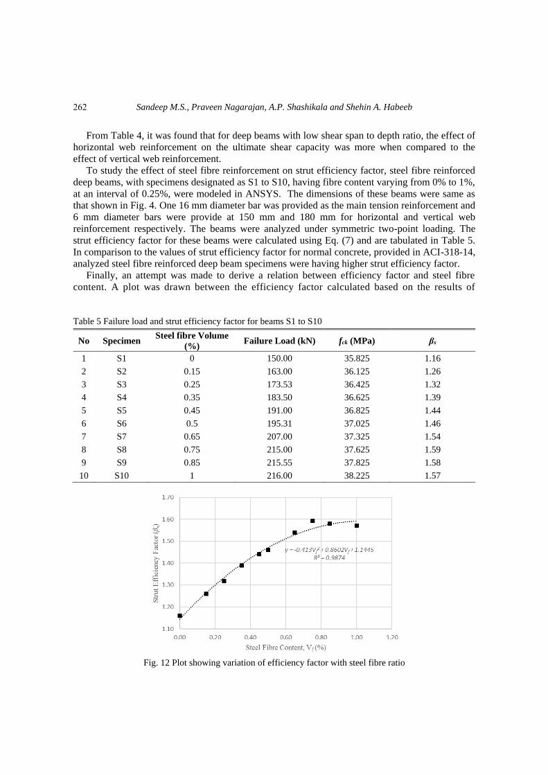
To study the effect of steel fibre reinforcement on strut efficiency factor, steel fibre reinforced
deep beams, with specimens designated as S1 to S10, having fibre content varying from 0% to 1%,
at an interval of 0.25%, were modeled in ANSYS. The dimensions of these beams were same as
that shown in Fig. 4. One 16 mm diameter bar was provided as the main tension reinforcement and
6 mm diameter bars were provide at 150 mm and 180 mm for horizontal and vertical web
reinforcement respectively. The beams were analyzed under symmetric two-point loading. The
strut efficiency factor for these beams were calculated using Eq. (7) and are tabulated in Table 5.
In comparison to the values of strut efficiency factor for normal concrete, provided in ACI-318-14,
analyzed steel fibre reinforced deep beam specimens were having higher strut efficiency factor.
Finally, an attempt was made to derive a relation between efficiency factor and steel fibre
content. A plot was drawn between the efficiency factor calculated based on the results of
Table 5 Failure load and strut efficiency factor for beams S1 to S10
No Specimen Steel fibre Volume
(%) Failure Load (kN) fck (MPa) βs
1 S1 0 150.00 35.825 1.16
2 S2 0.15 163.00 36.125 1.26
3 S3 0.25 173.53 36.425 1.32
4 S4 0.35 183.50 36.625 1.39
5 S5 0.45 191.00 36.825 1.44
6 S6 0.5 195.31 37.025 1.46
7 S7 0.65 207.00 37.325 1.54
8 S8 0.75 215.00 37.625 1.59
9 S9 0.85 215.55 37.825 1.58
10 S10 1 216.00 38.225 1.57
Fig. 12 Plot showing variation of efficiency factor with steel fibre ratio
262

Determination of strut efficiency factor for concrete deep beams with and without fibre
numerical analysis and the steel fibre content which is shown in Fig. 12. It can be seen from Table
5 that as the ratio of steel fibre increases, the strut efficiency factor also increases. It can be also
observed that beyond a steel fibre percentage of 0.75, there was no significant improvement in the
load carrying capacity. So 0.75% can be considered as the optimum steel fibre content.
From Fig. 12, an equation (Eq. (8)) was developed for representing the variation of strength
modification factor with respect to the steel fibre content where Vf stands for the steel fibre content
by volume in percentage in the concrete matrix
βs = -0.413Vf 2 + 0.8602Vf + 1.1445 (8)
Based on the study conducted it is found that the strut efficiency factor provided in
ACI318-14 is on the conservative side.
6. Conclusions
An attempt was made to check the effectiveness of efficiency factor proposed by ACI
318-14 for the analysis and design of reinforced concrete deep beams using STM method.
It was found that for deep beams with low shear span to depth ratio, the horizontal web
reinforcement was having more effect than the vertical web reinforcement on the ultimate
shear capacity. Based on the study conducted, strut efficiency factor for bottle-shaped
struts for ordinary reinforced concrete deep beams were found to be more than or equal to
1.0, in contrast to 0.75 given in ACI-318-14 for sufficiently reinforced bottle shaped strut
and 0.60 for unreinforced strut. In comparison to the strut efficiency factor provided in
ACI 318-14, strut efficiency factor obtained for steel fibre reinforced concrete beams were
higher. Based on the results of numerical analysis conducted, an equation was developed
for finding the value of efficiency factor with respect to the steel fibre content. More
experimental results are needed to further validate the equation which are in progress.
References
ANSYS, Inc., ANSYS Help, Release 12.1, Documentation, Copyright 2006.
ACI 318-14 (2014), Building code requirements for structural concrete and commentary, American
Concrete Institute, USA.
Andermatt, M.F. and Lubell, A.S. (2013b), “Strength modeling of concrete deep beams reinforced with
internal fiber-reinforced polymer”, ACI Struct. J., 110(4), 595-605.
Bahen, N. and Sanders, D.H. (2009), “Investigation of strut strength using a deep-beam database”, ACI
Struct. J., SP-265(18), 385-404.
Birrcher, D.B., Tuchscherer, R.G., Huizinga, M. and Bayrak, O. (2013), “Minimum web reinforcement in
deep beams”, ACI Struct. J., 110(2), 297-306.
Brown, Michael, D., Sankovich, Cameron, L., Bayrak, Oguzhan and Jirsa, James, O. (2006), “Behavior and
efficiency of bottle- shaped struts”, ACI Struct. J., 103(3), 348-355.
Chetchotisak, P., Teerawong, J. and Chetchotsak, D. (2014), “Efficiency factors for reinforced concrete deep
beams: part 1 - improved models”, Adv. Mater. Res., 931-932, 506-513.
Chetchotisak, P., Teerawong, J. and Chetchotsak, D. (2014), “Efficiency factors for reinforced concrete deep
beams: part2- code calibration”, Adv. Mater. Res., 931-932, 514-519.
263

Sandeep M.S., Praveen Nagarajan, A.P. Shashikala and Shehin A. Habeeb
Chetchotisak, P., Teerawong, J. and Yindeesuk, S. (2014), “New strut-and-tie-models for shear strength
prediction and design of RC deep beams”, Comput. Concrete, 14(1), 19-14.
Choi, H.B., Yi, C.K., Cho, H.H. and Kang, K.I. (2010), “Experimental study on the shear strength of
recycled aggregate concrete beams”, Magaz. Concrete Res., 62(2), 103-114.
Dupont, D. and Vandewalle, L. (2003), “Shear capacity of concrete beams containing longitudinal
reinforcement and steel fibers”, Am. Concrete Inst. Spec. Pub., 216, 79-94.
Hong, S. and Ha, T. (2012), “Effective capacity of diagonal strut for shear strength of reinforced concrete
beams without shear reinforcement”, ACI Struct. J., 109(2), 139-148.
Hussein, Hayder, H. and Kamonna (2010), “Non-linear analysis of steel fibre reinforced concrete deep
beams by ansys”, Kufa J. Eng., 2(1), 110-124.
Kim, D., Lee, J. and Lee, Y-H. (2014), “Effectiveness factor of strut-and-tie models for concrete deep beams
reinforced with FRP rebars”, Compos. Eng.: Part B, 56, 117-125.
Khan, M.A. and Ahmed, F.S. (2013), “Effect of web reinforcement on ultimate strength of reinforced
concrete deep beam”, Int. J. Eng. Res. Appl., 3(3), 516-519.
Lihua, X.U., Yin, C.H.I., Jie, S.U. and Dongtao, X.I.A. (2008), “Nonlinear finite element analysis of steel
fibre reinforced concrete deep beams”, Wuhan Univ. J. Nat. Sci., 13(2), 201-206.
Lu, W.Y., Hsiao, H.Tai., Chen, C.L., Huang, S.M. and Lin, M.C. (2015), “Tests of reinforced concrete deep
beams”, Comput. Concrete, 15(3), 357-372.
Mansur, M.A. and Ong, K.C.G. (1991), “Behavior of reinforced fibre concrete deep beams in shear”, ACI
Struct. J., 88(1), 98-105.
Narayanan, R. and Darwish, I.Y.S. (1988), “Fibre concrete deep beams in shear”, ACI Struct. J., 85(2), 141-
149.
Nagarajan, P. and Pillai, T.M.M. (2008), “Analysis and design of simply supported deep beams using strut
and tie method”, Adv. Struct. Eng., 11(5), 491-499.
Nagarajan, P. and Pillai, T.M.M. (2008), “Development of strut and tie models for simply supported deep
beams using topology optimisation”, Songklanakarin J. Sci. Technol., 30(5), 641-647.
Nagarajan, P. and Pillai, T.M.M. (2010), “Development of strut and tie models for continuous deep beams
using topology optimisation”, J. Struct. Eng., 37(4), 81-85.
Nehdi, N., Omeman, Z. and EI-Chabib, H. (2008), “Optimal efficiency factor in strut-and-tie model for
FRP-reinforced concrete short beams with (1.5<a/d<2.5)”, Mater. Struct., 41(10), 1713-1727.
Quntero-Febres, C.G., Parra-Montesinos, G. and Wight, J.K. (2006) “Strength of struts in deep concrete
members designed using strut-and-tie method”, ACI Struct. J., 103(4), 577-586.
Sahoo, D.K., Singh, B. and Bhargava, P. (2009), “An appraisal of the ACI strut efficiency factors”, Magaz.
Concrete Res., 61(6), 445-456.
Sahoo, D.K., Singh, B. and Bhargava, P. (2010), “Strut efficiency factors for structural concrete made from
coarse recycled concrete aggregates”, J. Struct. Eng., 37(1), 49-54.
Sahoo, D.K., Singh, B. and Pradeep Bhargava (2011), “Minimum reinforcement for preventing splitting
failure in bottle-shaped struts”, ACI Struct. J., 108(2), 206-216.
Sahoo, D.K., Flores, C.A. and Chao, Shih-Ho (2012), “Behavior of steel fibre-reinforced concrete deep
beams with large opening”, ACI Struct. J., 109(2), 193-204.
Schlaich, J., Schäfer, K. and Jennewein, K. (1987), “Towards a consistent design of structural concrete”, J.
Prestress. Concrete Inst., 32(3), 75-150.
Sclaich, J. and Schäfer, K. (1991), “Design and detailing of structural concrete using strut-and-tie models”,
Struct. Eng., 69(6), 113-125.
Tuchscherer, R., Birrcher, D., Huizinga, M. and Bayrak, O. (2011), “Distribution of stirrups across web of
deep beams”, ACI Struct. J., 108(1), 108-115.
Wolanski, A.J. (2004), “Flexural behaviour of reinforced and prestressed concrete beams using finite
element analysis”, Master’s Dissertation, Marquette University, Milwaukee.
CC
264