Embed Size (px)
Citation preview

Determination of the Induced Voltages by 220 kV Electric Overhead
Power Lines Working in Parallel and Narrow Routes. Measurements on
the Ground and Mathematical Model
FLAVIUS DAN SURIANU
Electrical Power Engineering Department
"Politehnica" University of Timisoara
300223 Timisoara, Bd. V. Parvan, Nr. 2, Timis
ROMANIA
Abstract: - The paper presents the measurements that the author has done in the South - West area of Romania
for the 220 kV double circuit overhead power lines having a passive circuit and an active one. It also describes
a mathematical simulation for determining the induced voltages by the active circuit into the disconnected one.
The measurements are compared with those obtained through calculations in order to validate the mathematical
model, becoming a useful tool for professionals in electric high voltage overhead power lines.
Key-words: electromagnetic interference, high voltage, induced voltage, electric capacity, mutual inductivity.
1 Introduction Electromagnetic fields of low frequency (50 Hz)
created by the overhead power transport and
distribution lines affect good working and service of
all electrical equipments placed nearby, and they
could also produce some unwanted effects on the
biological organisms located in that area. The
electro-magnetic disturbance field interferences
produce two different types of influences on all the
objects located in that area (including the nearby
electric lines), namely:
• Electric influences produced by capacitive
connections (couplings) between the phase
conductors of the three phase overhead power
lines and the nearby objects or electrical lines;
• Magnetic influences realized by inductive
couplings between the loops of the parallel and
adjacent circuits formed by the conductors and
the earth.
All these influences are physically reflected on
the voltage levels induced by the capacitive or inductive
connections in the electrical nearby circuits, on the
electric field intensity or potential from the earth,
and on the value of the magnetic induction in different
points, located near the power mains.
Knowing, as accurate as possible, these electro-magnetic parameters, especially those of the
voltages induced in a capacitive, respectively magnetic way, is necessary in order to search for methods and techniques that will be able to reduce
the unwanted effects and to increase the protection of the working staff.
• Measuring on the ground the electro-magnetic
parameters by using specialized equipment. This
method is very important to establish some
relative values, and could be used as a real
reference for all the other methods. But it has
some disadvantages related to the limited
opportunities of realizing physically the various
operating regimes in real conditions of
exploitation, to the emergence of relatively great
measuring errors, and to the impossibility of
measuring overhead high voltage electrical lines
in any locations in the vicinity of the power lines;
• Experimental determinations in high voltage
specialized laboratories, using physical models
able to simulate the real situation. This method
allows, theoretically, the realization of all service
regimes, but, even if it is intuitive from the
physical point of view, it is restrictive from the
point of view of being extended to all power line
dimensions of any type and it is also affected by
errors due to specific laboratory conditions;
• Mathematical modeling of electro-magnetic
interferences, which, by using modern and fast computing software, allows the numerical
determination of all the parameters of the power line, in any point located nearby and for any
service regime. This method, although fast, simple and generally efficient, could not be valid and sure unless the results it offers are comparable
WSEAS TRANSACTIONS on POWER SYSTEMS Flavius Dan Surianu
ISSN: 1790-5060 264 Issue 8, Volume 4, August 2009

to those obtained by at least one of the two experimental methods described above.
Taking into account the advantages of mathematical modeling and the necessity of the experimental validation of these models, this paper
presents a comparison between the author’s results obtained by measuring on the ground the voltages
induced electrically and magnetically on the passive circuit of the double circuit overhead lines of 220 kV
from area Banat - România and those obtained by using a specific software application.
2 Measuring on the ground the
induced voltages All the measurements carried out on the double
circuit 220 kV overhead power lines, area Banat -
Romania, during the autumn of 2006 had, as a
unique task, the determination of the
electromagnetic stress level that appears on a
disconnected circuit when, in parallel, there is a
second circuit operating in a normal regime. Such a
situation is frequently met in the operation of high
voltage overhead power lines with double circuit
when one of the circuits has to be passivated in
order to perform the revision or repair works. In this
case, immediately after disconnection, in the
passivated ground insulated circuit, voltages
induced by electrical coupling occur on each phase,
and when the earthing and short-circuit devices
close down, the voltages induced by capacitive
coupling are canceled, but there occur voltages
induced by inductive coupling, forcing the
emergence of induced currents in loops formed by
each of the three phases of the passivated circuit and
earth. Taking into account both types of
disturbances affecting the passivated power circuit,
at first the measurements concerned the voltages
induced by capacitive coupling in each of the 3
phases, and then the voltages induced by inductive
coupling in the 3 loops of the passive circuit
connected to earth through short-circuit devices, at
one of the ends.
In order to determine practically the voltages
induced by the two types of electromagnetic
couplings, the following procedures have been used:
a) If the three phase circuit conductors of the interrupted line are not connected to the earth by
short-circuit devices, in this way being isolated from ground, the interrupted phase conductors
will have a much smaller potential than the active phase conductor potentials existing
nearby. In this case, between the active phase conductors and those of the passivated one,
electric couplings will occur, the conductors having the role of fittings of huge condensers
having the air as a dielectric medium. Depending on the intensity of the electric coupling (dependent on the distances between
conductors and the length of the portion of parallelism between the lines) the interrupted
circuit phase conductor potentials will depend on earth potential. A possible measurement of
these potentials (voltages induced by capacitive coupling) is shown in Fig. 1.
Fig. 1. The measurement of the voltage induced through
capacitive coupling in the passive circuit of a double
circuit high voltage overhead power line
b) If discontinued three phased circuit conductors
are linked to the earth at both ends, by short-
circuit devices, there are three loops formed, in
which intense electromagnetic fields of the
currents of the active line will induce
electromotive voltages (EMV) forcing the closure
of the induced currents, the coupling being a
magnetic one (Fig. 2).
Fig. 2. Magnetic coupling between the active circuit and
the passivated one of a double circuit high voltage
overhead power line
In this case, in order to measure the
electromotive voltages (EMV) induced in the
passivated circuit phases the short-circuit devices
from one end of the line have to be opened and a
voltmeter should be set, as seen in Fig. 3.
Fig. 3. The measurement of the EMV induced trough
inductive coupling in the passivated circuit of a double
circuit high voltage overhead power line
WSEAS TRANSACTIONS on POWER SYSTEMS Flavius Dan Surianu
ISSN: 1790-5060 265 Issue 8, Volume 4, August 2009

In the area of Banat - Romania, which includes 4
counties, there are several 220 kV overhead electric
power lines that work in parallel on double circuit
pole structure on portions of different lengths,
loading different consumers. Depending on the load
of these lines, in the case of the disconnection of a
circuit, voltages induced by electrical and magnetical
coupling will occur in the disconnected circuit, these
voltages having to be known. The most unfavorable
cases will be those in which the active circuit,
remained in service, is long and supplies large
power consumers. Fig. 4 shows the configuration of
overhead electric power lines of 220 kV from area
Banat - Romania.
Fig. 4. The diagram of 220 kV overhead electric power lines from county Banat - Romania
Taking into account the fact that the support
poles of most of the lines are of the same
configuration, as in Table 1, the main geometrical
data for different types of supporting poles used for
double circuit 220 kV lines are given, these data
corresponding to the general geometric distances
shown in Fig. 5.
Table 1. The size of the support poles for 220 kV overhead electric power lines whith double circuit
No. Pole type H (m) a1 (m) h1(m) h2 (m) d1 (m) d2 (m) d3 (m) λiz (m) fmax (m) hg (m)
1 Sn 220.201 41,4 6,4 6,5 6,5 5,0 8,0 5,0 2,541 14,0 5,459
2 Sn 220.202 41,4 6,4 6,5 6,5 5,0 8,0 5,0 2,541 14,0 5,459
3 Sn 220.204 42,5 5,5 6,5 6,5 4,5 8,0 5,0 2,541 14,0 7,459
4 Sn 220.205 42,5 5,5 6,5 6,5 4,5 8,0 5,0 2,541 14,0 7,459
5 Ss 220.205 44,9 6,9 8,0 8,0 5,5 9,5 5,5 2,541 14,0 5,459
6 Ss 220.206 46,0 6,0 8,0 8,0 4,75 9,25 5,25 2,541 14,0 7,459
c1
c2
c3
a 1a 2
a 3
λiz
hg
fmax
a
Fig. 5. The diagram of the geometry of a support pole
The active phase conductors of lines are of Steel-Aluminium type with standard sections of 400 mm2 or 450 mm2, this being specified for each electric
line. In order to carry out the measurements of
induced voltages, there has been used a program of measurements with well defined steps, to protect the working staff from exposure to high voltages. This
program has included all the necessary steps to be taken when working in high voltage exposure
conditions. It was divided into the following steps:
WSEAS TRANSACTIONS on POWER SYSTEMS Flavius Dan Surianu
ISSN: 1790-5060 266 Issue 8, Volume 4, August 2009
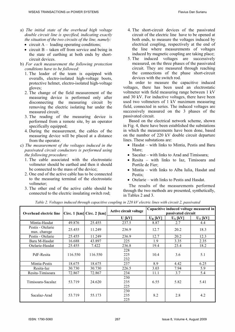
a) The initial state of the overhead high voltage double circuit line is specified, indicating exactly the situation of the two circuits of the line, namely:
• circuit A – loading operating conditions;
• circuit B – taken off from service and being in the state of earthing at both ends by short-circuit devices.
b) For each measurement the following protection conditions have to be followed: 1. The leader of the team is equipped with
overalls, electro-isolated high-voltage boots, protective helmet, electro-isolated high-voltage gloves;
2. The change of the field measurement of the measuring device is performed only after disconnecting the measuring circuit by removing the electric isolating bar under the measured circuit;
3. The reading of the measuring device is performed from a remote site, by an operator specifically equipped;
4. During the measurement, the cables of the measuring device will be placed at a distance from the operator.
c) The measurement of the voltages induced in the passivated circuit conductors is performed using the following procedure: 1. The cable associated with the electrostatic
voltmeter should be earthed and then it should be connected to the mass of the device;
2. One end of the active cable has to be connected to the measuring terminal of the electrostatic voltmeter;
3. The other end of the active cable should be connected to the electric insulating switch rod;
4. The short-circuit devices of the passivated circuit of the electric line have to be opened at both ends, to measure the voltages induced by electrical coupling, respectively at the end of the line where measurements of voltages induced by magnetic coupling are taking place;
5. The induced voltages are successively measured, on the three phases of the passivated circuit. They are measured through reaching the connections of the phase short-circuit devices with the switch rod.
In order to measure the capacitive induced voltages, there has been used an electrostatic voltmeter with field measuring range between 1 kV and 30 kV. For inductive voltages, there have been used two voltmeters of 1 kV maximum measuring field, connected in series. The induced voltages are successively measured on the 3 phases of the passivated circuit.
Based on the electrical network scheme, shown in Fig. 4, there have been established the substations in which the measurements have been done, based on the number of 220 kV double circuit departure lines. These substations are:
• Hasdat – with links to Mintia, Pestis and Baru Mare;
• Sacalaz – with links to Arad and Timisoara;
• Resita – with links to Iaz, Timisoara and Portile de Fier;
• Mintia – with links to Alba Iulia, Hasdat and Pestis;
• Otelarie – with links to Pestis and Hasdat.
The results of the measurements performed through the two methods are presented, synthetically, in Tables 2 and 3.
Table 2. Voltages induced through capacitive coupling in 220 kV electric lines with circuit 2, passivated
Overhead electric line Circ. 1 [km] Circ. 2 [km] Active circuit voltage
Capacitive induced voltage measured in passivated circuit
U [kV] UR [kV] US [kV] UT [kV]
Mintia-Hasdat 49.876 25.455 237.5 8.87 2.7 4.4
Pestis - Otelarie max. charege
25.455 11.249 236.9 12.7 20.2 18.3
Pestis - Otelarie 25.455 11.249 236.9 12.7 20.2 12.3
Baru M-Hasdat 16.688 43.897 225 1.9 3.35 2.35
Otelarie-Hasdat 25.455 7.422 236.8 19.4 23.4 18.2
PdF-Resita 116.550 116.550 228 225 232
10.4 3.6 5.1
Mintia-Pestis 18.675 18.675 237 8.9 4.42 6.25
Resita-Iaz 30.730 30.730 226.5 3.03 7.94 5.9
Resita-Timisoara 72.867 72.867 234 11.1 3.7 5.4
Timisoara-Sacalaz 53.719 24.620 230 235 225
6.55 5.82 5.41
Sacalaz-Arad 53.719 55.173 230 235 225
8.2 2.8 4.2
WSEAS TRANSACTIONS on POWER SYSTEMS Flavius Dan Surianu
ISSN: 1790-5060 267 Issue 8, Volume 4, August 2009

Table 3. Voltages induced through inductive coupling in 220 kV electric lines with circuit 2, passivated
Overhead electric line
Circ. 1 [km]
Circ. 2 [km]
Activ circuit voltage
Active circuit current
Magnetically induced voltage measured in
passivated circuit
Active and reactive power flow and initial phase difference voltage -
currents
U [kV]
I [A]
UR [V]
US [V]
UT [V]
P [MW]
Q [MVAR]
cos φ φ
[rad]
Mintia-Hasdat 49.876 25.455 237.5 265.75 320 21 120 107 22 0.9795 0.2028
Pestis - Otelarie max. charge
25.455 11.249 236.9 156.9 68 10.2 39 50 40 0.781 0.6745
Pestis-Otelarie 25.455 11.249 236.9 74.826 34 10.2 18.5 24.9 17.9 0.812 0.6232
Baru M-Hasdat 16.688 43.897 225 181.68 120 26 122 5 5 0.707 0.7855
Otelarie-Hasdat 25.455 7.422 236.8 92.542 11 4.3 13.2 28.5 25 0.7518 0.72
PdF-Resita 116.550 116.550 228 225 232
440 480 460
1400 400 1440 182 7.354 0.98 0.2003
Mintia-Peştiş 18.675 18.675 237 71.77 63.6 13 42 29 5 0.985 0.1734
Resita-Iaz 30.730 30.730 226.5 14.54 20.8 3.6 17 0 5.7 0 1.57
Resita-Timisoara
72.867 72.867 234 497.03 1020 400 940 200 22 0.988 0.155
Timisoara-Sacalaz
53.719 24.620 230 235 225
212 237 218
180 71 1260 50 10.15 0.98 0.2003
Sacalaz-Arad 53.719 55.173 230 235 225
212 237 218
310 80 270 50 10.15 0.98 0.2003
The length of parallelism between the active line
and passive line influences the value of the induced voltage regardless the type of electromagnetic coupling. To follow this phenomenon, the curves of the induced voltages have been raised depending on the parallel portion lengths. The resulting curves are shown in Fig. 6 and Fig. 7.
Fig. 6. The variation of the voltage induced through capacitive coupling depending on the length of the
parallelism with double circuit 220 kV electric power lines having a passivated circuit
Fig. 7. The variation of the voltage induced through inductive coupling depending on the length of the
parallelism with double circuit 220 kV electric power lines having a passivated circuit
Analyzing Fig. 6 and 7, we observe that on small distances of parallelism, up to about 20 km, the
length of the line has a small influence on the induced voltages. On these distances, a number of
other causes are more powerful in influencing the value of the induced voltage, regardless the way in which the electromagnetic interference between the
active circuit and passivated one is done. At greater lengths, over 20 km, the value of the voltage
induced through electrical coupling (capacitive) and the magnetic coupling have got an increasing linear trend depending on the parallelism distance length.
3 Mathematical models for
determining the induced voltages The advantage of the measurements on the ground made possible the existence of a database for
mathematical modeling, because the results obtained by it can be checked by comparison with the real
ones. This was the basis of designing mathematical models, by trying to imitate as accurately as possible, the physical phenomena that happen in nature.
Considering that at low frequencies, couplings between sources and victims of EMI can be separated
by different experiments, in electrical couplings and magnetic couplings, the mathematical modeling will take into account this observation that leads to two
different models, one for the electric phenomena and another one for the magnetic phenomena.
WSEAS TRANSACTIONS on POWER SYSTEMS Flavius Dan Surianu
ISSN: 1790-5060 268 Issue 8, Volume 4, August 2009

Regardless the type of electromagnetic coupling,
the values of induced voltages depend on the
geometry of electrical lines, and on the loads
transported through them. Therefore, mathematical
models have to include, in a first stage, the
geometric calculation of the power line poles with
double circuit and also the determination of
capacities and mutual inductivities between the
conductors of double circuit electric power lines.
The calculation of geometrical parameters of a line
pole for double circuit overhead electric power line
taking into account both the distances between the
conductors of the double circuit and the distances
between the conductors and their images from the
ground, and the maximum arrow made by the
conductors of the line in a standard, horizontal
opening, as shown in Fig. 8, a and b, is done as
following:
a) b)
Fig. 8. Determination of the geometric parameters of a high voltage overhead power line with double circuit.
a) Geometric pole parameters. b) Determination of the average height of the conductors above the ground
a) The average distance between the conductors and
the return path through earth is obtained taking
into account the earth resistivity, using the
following relation:
550CPDf
ρ= , (1)
where ρ - the earth resistivity and f - line voltage
frequency.
b) Average heights of the line conductors above the
ground level result from:
1 max
2
3k izk kh H a fλ= − − − (2)
c) Vertical and horizontal distances of active
conductors for each type of pole given in Table 1,
are determined by the following relations:
( )22
1 2 1RS rsd d h d d= = + −
( )22
2 2 3ST std d h d d= = + − (3)
( ) ( )2 2
1 2 3 1RT rtd d h h d d= = + + −
d) The distances between the conductors of the two
circuits of the electric line with double circuit
result from the following relations:
1 2 32 ; 2 ; 2Rr Ss Ttd d d d d d= = =
( )22
1 2 12Sr Rsd d h d d= = + −
( )22
2 2 32Ts Std d h d d= = + − (4)
( ) ( )2 2
1 2 3 12Tr Rtd d h h d d= = + + −
3.1 Mathematical modeling
of the electric coupling
In the case of capacitive coupling, the electric line
with double circuit represents a complex set of
capacities that are formed due to the differences in
potential both between the active circuit phases
(because of the different values of voltage phasers
of the three phases at any moment), and the active
circuit conductors and those of the passivated and
insulated from the ground circuit. The set of
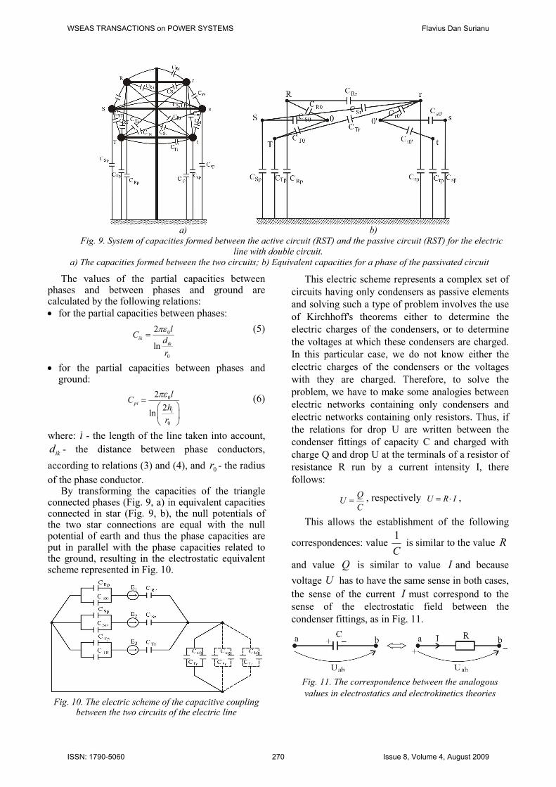
capacities that are formed are shown in Fig. 9.
WSEAS TRANSACTIONS on POWER SYSTEMS Flavius Dan Surianu
ISSN: 1790-5060 269 Issue 8, Volume 4, August 2009
a) b)
Fig. 9. System of capacities formed between the active circuit (RST) and the passive circuit (RST) for the electric
line with double circuit.
a) The capacities formed between the two circuits; b) Equivalent capacities for a phase of the passivated circuit
The values of the partial capacities between phases and between phases and ground are calculated by the following relations:
• for the partial capacities between phases:
0
0
2
lnik
ik
lC
d
r
πε=
(5)
• for the partial capacities between phases and ground:
0
0
2
2ln
pi
i
lC
h
r
πε=
(6)
where: l - the length of the line taken into account,
ikd - the distance between phase conductors,
according to relations (3) and (4), and 0r - the radius
of the phase conductor. By transforming the capacities of the triangle
connected phases (Fig. 9, a) in equivalent capacities connected in star (Fig. 9, b), the null potentials of the two star connections are equal with the null potential of earth and thus the phase capacities are put in parallel with the phase capacities related to the ground, resulting in the electrostatic equivalent scheme represented in Fig. 10.
Fig. 10. The electric scheme of the capacitive coupling between the two circuits of the electric line
This electric scheme represents a complex set of
circuits having only condensers as passive elements
and solving such a type of problem involves the use
of Kirchhoff's theorems either to determine the
electric charges of the condensers, or to determine
the voltages at which these condensers are charged.
In this particular case, we do not know either the
electric charges of the condensers or the voltages
with they are charged. Therefore, to solve the
problem, we have to make some analogies between
electric networks containing only condensers and
electric networks containing only resistors. Thus, if
the relations for drop U are written between the
condenser fittings of capacity C and charged with
charge Q and drop U at the terminals of a resistor of
resistance R run by a current intensity I, there
follows:
QU
C= , respectively U R I= ⋅ ,
This allows the establishment of the following
correspondences: value 1
C is similar to the value R
and value Q is similar to value I and because
voltage U has to have the same sense in both cases,
the sense of the current I must correspond to the
sense of the electrostatic field between the
condenser fittings, as in Fig. 11.
Fig. 11. The correspondence between the analogous
values in electrostatics and electrokinetics theories
WSEAS TRANSACTIONS on POWER SYSTEMS Flavius Dan Surianu
ISSN: 1790-5060 270 Issue 8, Volume 4, August 2009

Based on the analogies between the values in
electrostatics and electrokinetics theories, the
equivalent electrokinetic scheme has been built, as
presented in Fig. 12.
Fig. 12. The analogous electrokinetic scheme of the
capacitive coupling for a phase of the passivated circuit
In order to determine the voltages induced by
capacitive coupling, the Kirchhoff’s theorems could
be applied in the case of the analogous electrokinetic
scheme from Fig. 12. Thus the following system of
equations (7) is resulting, where currents of edge
circuits are unknown:
( ) ( )1 2 10 12 1 20 22 2E E R R I R R I− = + ⋅ − + ⋅
( ) ( )2 3 20 22 2 30 32 3E E R R I R R I− = + ⋅ − + ⋅
( )3 30 32 3 eE R R I R I= + ⋅ + ⋅ (7)
1 2 3I I I I+ + =
Solving the system of equations (7) and
considering the analogies I Q≡ and
0
1ei
i ip
RC C
≡+
, there results the value of induced
capacitive voltage in each of the three conductors of
the passivated circuit of the line with double circuit,
i.e.:
fi ei iU R I= ⋅ , respectively
0
ifi
i ip
QU
C C=
+ (8)
Observations:
1. The analogies between electrostatic and
electrokinetic values are correct and valid only
for circuits in DC (direct current). But in this
case, the analyzed circuits are in alternative
current (AC) because the sources of voltage
1 2,E E and 3E are alternatively sinusoidal having
the following expressions:
( )1 2 sinfRE U tω φ= ⋅ ⋅ +
2
22 sin
3fSE U t
πω φ
⋅ = ⋅ ⋅ + −
(9)
3
42 sin
3fTE U t
πω φ
⋅ = ⋅ ⋅ + −
where 2 fω π= ⋅ ⋅ - angular frequency of the
sinusoidal wave of the phase voltage and 0φ = -
initial phase difference, considered null because the
relative positions of the voltage phasers related to
the fixed reference axis of the phaser system are not
known.
Because the analogies should be valid in this
case too, it is necessary to consider time as a
constant value. But time, t = const. represents
exactly the moment of measurement of the voltages
capacitively induced for each phase of the
passivated circuit of the analyzed electric line. In
order to determine the moment of measurement,
there has been considered a period of the sinusoidal
wave voltage, that, at frequency f = 50 Hz has the
duration T = 0.02 seconds. Period, T, of the
sinusoidal wave has been divided into 100 discreet
and constant time intervals of 0.0002t∆ = seconds,
and thus by discreeted the time, the varying values
of AC circuits have been converted into constant
values on the intervals , 1...100,kt k∆ = for which
the analogies considered become valid. Knowing
through measurements, the capacitively induced
voltages in the conductors of the passivated circuit
of the electric line, by assigning 2-3 values to time
intervals, t∆ , and using a computing program
developed in MATHCAD 11 to solve the equations
(7), from relations (8), there result the calculated
values of the capacitive induced voltages. These
values are given in Table 4, compared with the
measured ones. The values measured and those
obtained by calculation are very close, this
demonstrating the validity of the adopted
mathematical model.
2. The mathematical model presented above also
allows the determination of the maximum value
of the capacitive voltage induced in each phase of
the passivated circuit of the line, by assigning discrete
values to time intervals around the maximum of
the sinusoidal function of the inductive voltage.
3. For each phase of the passivated circuit, a different
value of the discreet time has been adopted because
the measurements were performed for each phase
separately.
WSEAS TRANSACTIONS on POWER SYSTEMS Flavius Dan Surianu
ISSN: 1790-5060 271 Issue 8, Volume 4, August 2009

Table 4. Comparison between the measured and calculated capacitively induced voltages
Overhead electric
line Circ. 1 [km] Circ. 2 [km]
Activ circuit
voltage
Capacitively induced voltage
measured in passivated circuit
Capacitively induced
voltage calculated in
passivated circuit
U [kV] UR [kV] US [kV] UT [kV] Ur [kV] Us [kV] Ut [kV]
Mintia-Hasdat 49.876 25.455 237.5 8.87 2.7 4.4 8.823 2.755 4.415
Pestis.-Otelarie
max. charge 25.455 11.249 236.9 12.7 20.2 18.3 12.643 20.324 12.278
Pestis-Otelarie 25.455 11.249 236.9 12.7 20.2 12.3 12.726 20.324 12.278
Baru M-Hasdat 16.688 43.897 225 1.9 3.35 2.35 1.845 3.419 2.427
Otelarie-Hasdat 25.455 7.422 236.8 19.4 23.4 18.2 19.433 23.259 17.906
PdF-Resita 116.55 116.55
228
225
232
10.4 3.6 5.1 10.422 3.619 4.948
Mintia-Pestis 18.675 18.675 237 8.9 4.42 6.25 9.076 4.573 6.278
Resita-Iaz 30.730 30.730 226.5 3.03 7.94 5.9 3.154 7.998 5.876
Resita-Timisoara 72.867 72.867 234 11.1 3.7 5.4 11.221 3.768 4.798
Timisoara-Sacalaz 53.719 24.620
230
235
225
6.55 5.82 5.41 6.582 5.865 5.452
Sacalaz-Arad 53.719 55.173 230 235
225
8.2 2.8 4.2 8.206 2.845 4.210
3.2 Mathematical modeling
of the magnetic coupling Inductive coupling is generated by electric currents varying in time which pass through the conductors
of the active circuit of the electric line with double circuit whose variable electric and magnetic fields induce electromotive voltages (EMV) in the conductors
of the passivated circuit. The mathematical expression of the currents from the active circuit conductors is
given by relations (10), namely:
( )2 sinR fRi I tω ϕ= ⋅ ⋅ +
22 sin
3S fSi I t
πω ϕ = ⋅ ⋅ + −
(10)
42 sin
3T fTi I t
πω ϕ = ⋅ ⋅ + −
where φ represents the difference of phase between
voltages and currents of the active circuit and it is
known because the powers P and Qwith which the
active circuit is charged are known, according to Table 2.
In the network model, the magnetic coupling can
be represented by mutual inductivities between the conductors of the two circuits whose general
expression is:
( )0 1 2
1220 2
1 2 124
l dl dlM
l l d
µπ
=− +
∫ (11)
where, 1l and 2l are the lengths of the two parallel
conductors and 12d is the distance between them.
After developing the square root in series and neglecting the terms of higher rank, the relation (11)
becomes:
0 ln ,2
cp
ik
ik
DM l
d
µπ
= ⋅ ⋅
(12)
where ( ), , ,i R S T∈ respectively ( ), ,k r s t∈ .
But because the electromotive voltage (EMV) induced in each of the three conductors of the
passivated circuit represents the contribution of all the three inductive magnetic fields generated by variable currents of the active circuit, the mathematical
expression for each phase of the passivated circuit is:
( )r R Rr S Sr T TrU j i M i M i Mω= − ⋅ ⋅ ⋅ + ⋅ + ⋅
( )s R Rs S Ss T TsU j i M i M i Mω= − ⋅ ⋅ ⋅ + ⋅ + ⋅ (13)
( )t R Rt S St T TtU j i M i M i Mω= − ⋅ ⋅ ⋅ + ⋅ + ⋅
The calculating algorithm, presented, above has
been the basis of a computing program in MATHCAD 11, with which there have been
determined analytically the voltages induced by magnetic coupling in the passivated circuits of the
electric lines of 220 kV double circuit-Banat area of Romania. In Table 5, the analytical results are presented compared with those measured on the
ground. Observation: Taking into account φ, the
difference of phase between voltage and current, through which the loading of the inductive circuit is expressed indirectly has required that the
representation of the current be done through
WSEAS TRANSACTIONS on POWER SYSTEMS Flavius Dan Surianu
ISSN: 1790-5060 272 Issue 8, Volume 4, August 2009
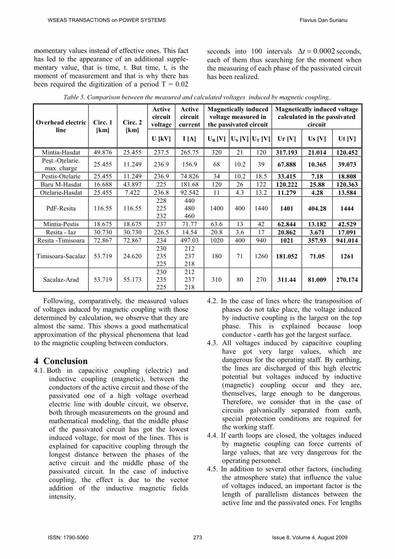
momentary values instead of effective ones. This fact has led to the appearance of an additional supple-
mentary value, that is time, t. But time, t, is the moment of measurement and that is why there has been required the digitization of a period T = 0.02
seconds into 100 intervals 0.0002t∆ = seconds,
each of them thus searching for the moment when the measuring of each phase of the passivated circuit
has been realized.
Table 5. Comparison between the measured and calculated voltages induced by magnetic coupling,.
Overhead electric
line
Circ. 1
[km]
Circ. 2
[km]
Active
circuit
voltage
Active
circuit
current
Magnetically induced
voltage measured in
the passivated circuit
Magnetically induced voltage
calculated in the passivated
circuit
U [kV] I [A] UR [V] US [V] UT [V] Ur [V] Us [V] Ut [V]
Mintia-Hasdat 49.876 25.455 237.5 265.75 320 21 120 317.193 21.014 120.452
Peşt.-OŃelarie.
max. charge 25.455 11.249 236.9 156.9 68 10.2 39 67.888 10.365 39.073
Pestis-Otelarie 25.455 11.249 236.9 74.826 34 10.2 18.5 33.415 7.18 18.808
Baru M-Hasdat 16.688 43.897 225 181.68 120 26 122 120.222 25.88 120.363
Otelarie-Hasdat 25.455 7.422 236.8 92.542 11 4.3 13.2 11.279 4.28 13.584
PdF-Resita 116.55 116.55
228
225
232
440
480
460
1400 400 1440 1401 404.28 1444
Mintia-Pestis 18.675 18.675 237 71.77 63.6 13 42 62.844 13.182 42.529
Resita - Iaz 30.730 30.730 226.5 14.54 20.8 3.6 17 20.862 3.671 17.091
Resita -Timisoara 72.867 72.867 234 497.03 1020 400 940 1021 357.93 941.014
Timisoara-Sacalaz 53.719 24.620
230
235
225
212
237
218
180 71 1260 181.052 71.05 1261
Sacalaz-Arad 53.719 55.173
230
235 225
212
237 218
310 80 270 311.44 81.009 270.174
Following, comparatively, the measured values
of voltages induced by magnetic coupling with those determined by calculation, we observe that they are almost the same. This shows a good mathematical
approximation of the physical phenomena that lead to the magnetic coupling between conductors.
4 Conclusion 4.1. Both in capacitive coupling (electric) and
inductive coupling (magnetic), between the conductors of the active circuit and those of the passivated one of a high voltage overhead
electric line with double circuit, we observe, both through measurements on the ground and
mathematical modeling, that the middle phase of the passivated circuit has got the lowest induced voltage, for most of the lines. This is
explained for capacitive coupling through the longest distance between the phases of the
active circuit and the middle phase of the passivated circuit. In the case of inductive
coupling, the effect is due to the vector addition of the inductive magnetic fields intensity.
4.2. In the case of lines where the transposition of
phases do not take place, the voltage induced by inductive coupling is the largest on the top phase. This is explained because loop
conductor - earth has got the largest surface. 4.3. All voltages induced by capacitive coupling
have got very large values, which are dangerous for the operating staff. By earthing, the lines are discharged of this high electric
potential but voltages induced by inductive (magnetic) coupling occur and they are,
themselves, large enough to be dangerous. Therefore, we consider that in the case of
circuits galvanically separated from earth, special protection conditions are required for the working staff.
4.4. If earth loops are closed, the voltages induced by magnetic coupling can force currents of
large values, that are very dangerous for the operating personnel.
4.5. In addition to several other factors, (including
the atmosphere state) that influence the value of voltages induced, an important factor is the
length of parallelism distances between the active line and the passivated ones. For lengths
WSEAS TRANSACTIONS on POWER SYSTEMS Flavius Dan Surianu
ISSN: 1790-5060 273 Issue 8, Volume 4, August 2009

of more than 20 km, the value of induced voltages increases, practically, linearly with the
length of the parallelism distance. 4.6. Mathematical models developed to simulate the
phenomena of electric and magnetic coupling
between the conductors of circuits of overhead high-voltage electric line with double circuit
lead to results which are very close to those obtained by direct measurements on the
ground, in real working situations. This turns mathematical models into useful tools for studying the phenomena of electromagnetic
interference (EMI) at low frequency in case of overhead electric lines when operating on
parallel and narrow paths.
References:
[1] X1. Author, Title of the Paper, International Journal of Science and Technology, Vol.X,
No.X, 200X, pp. XXX-XXX. [2] X2. Author, Title of the Book, Publishing
House, 200X.
[1] Surianu F.D., Compatibilitate Electromagnetica. AplicaŃii în Sistemele Electroenergetice. Editura Orizonturi Universitare Timisoara,
2006, ISBN 973-638-244-3, ISBN 978-973-638-244-4; (in Romanian languege);
[2] Surianu F.D., An apparatus for signalizing the induced currents in the disconnected circuits of double circuit h.v. overhead lines, Scientific Bull.
of UPT, Serie Energetics, Tom 50(64), Fasc.1-2, Nov., 2007, pp. 615-620, ISSN 1582-7194;
[3] Surianu F.D., Masurarea tensiunilor induse in LEA 220 kV d.c. si pe portiuni de paralelism cu
LEA 110 kV, contract de cercetare, Timisoara, 2006; (in Romanian language);
[4] Munteanu C., Topa V., Muresan T., Costin A.M., Electromagnetic Interferences between
HV Power Lines and RBS Antennas Mounted on HV Tower, Proceedings of the 6th International Symposium on Electromagnetic
Compatibility, EMC Europe, 2009, Eindhoven, Holland, pp. 878-881;
[5] TTU-T and CIGRE, Protection Measure for Radio Base Stations Sited on Power Line
Towers, Recommendation K 57, 2003. [6] Sanchez Santiago A.J., Yuste A..J., Menoz
Expozito J.E., Garcia Galan S., A Balanced
Scheduler for Grid Computing, Proceedings of the 8th WSEAS International Conference on
Simulation, Modelling and Optimization (SMO ’08), Santander, Calabria, Spain, September 23-25, 2008, pp. 59-64 ISSN 1790-2769, ISBN
978-960-474-007-9. [7] Kenedy Aliila Greyson, Anant Oonsivilai,
Identifying Critical Measurements in Power System Network, Proceedings of The 8th WSEAS International Conference on Electric
Power Systems, High Voltage, Electric Machines (POWER ’08), Venice, Italy, 21-23
November, 2008, pp. 61-66, ISSN 1790-5117, ISBN 978-960-474-026-0.
[8] Isaramongkolrak A., Kulworawanichpong T.,
Pao-La-Or P., Influence of an Overhead Ground Wire on Electric Fields Around the HV
Power Transmission, Proceedings of The 8th WSEAS International Conference on Electric Power Systems, High Voltage, Electric
Machines (POWER ’08), Venice, Italy, 21-23 November, 2008, pp. 128-132, ISSN 1790-
5117, ISBN 978-960-474-026-0.
WSEAS TRANSACTIONS on POWER SYSTEMS Flavius Dan Surianu
ISSN: 1790-5060 274 Issue 8, Volume 4, August 2009