Embed Size (px)
Citation preview
177Determination of the JWL Constants for ANFO and Emulsion Explosives...
Central European Journal of Energetic Materials, 2015, 12(2), 177-194
Determination of the JWL Constants for ANFO and Emulsion Explosives from Cylinder Test Data
Jose A. SANCHIDRIÁN*, Ricardo CASTEDO, Lina M. LÓPEZ, Pablo SEGARRA, Anastasio P. SANTOS
Universidad Politécnica de Madrid − E.T.S.I. Minas y Energía,Ríos Rosas 21, 28003 Madrid, Spain*E-mail: [email protected]
Abstract: The Jones-Wilkins-Lee (JWL) equation of state parameters for ANFO and emulsion-type explosives have been obtained from cylinder test expansion measurements. The calculation method comprises a new radial expansion function, with a non-zero initial velocity at the onset of the expansion in order to comply with a positive Gurney energy at unit relative volume, as the isentropic expansion from the CJ state predicts. The equations reflecting the CJ state conditions and the measured expansion energy were solved for the JWL parameters by a non-linear least squares scheme. The JWL parameters of thirteen ANFO and emulsion type explosives have been determined in this way from their cylinder test expansion data. The results were evaluated through numerical modelling of the tests with the LS-DYNA hydrocode; the expansion histories from the modelling were compared with the measured ones, and excellent agreement was found.
Keywords: cylinder test, JWL equation of state, LS-DYNA, ANFO, emulsion explosives
1 Introduction
The cylinder test was developed at the Lawrence Livermore Laboratory (LLNL) [1, 2] with the aim of characterizing the adiabatic expansion of the detonation products, by measuring the motion of the cylinder wall as it is expanded by the detonation products of the explosive charge inside. The cylinder test typically yields an expansion radius history curve that can be associated with the relative expansion volume and the Gurney-type energy density. The expansion energy
ISSN 1733-7178e-ISSN 2353-1843
178 J.A. Sanchidrián, R. Castedo, L.M. López, P. Segarra, A.P. Santos
function of the volume obtained in the cylinder test is commonly used to derive the detonation products equation of state, of which the JWL (Jones-Wilkins-Lee) [1] is the most widely used.
While originally designed for military explosives, the cylinder test has also been used for characterizing commercial compositions [3-10]. Of these, ANFOs and emulsions currently cover the vast majority of explosives in civil applications. A practical approach to the numerical modelling of these explosives and their interaction with, for example rock, is to have a library of equation of state parameter sets for a sufficiently ample range of densities, diameters and detonation velocities. Since these characteristics are usually known for a given blasting application (e.g. the detonation velocity is easily measured on-site for the actual diameter, density and surrounding rock), the modelling can be accomplished by selecting a parameter set of a similar composition, with properties and test characteristics as close as possible to the ones for the explosive in the application concerned. Then the use of a simple burn model, provided it complies with the experimental detonation velocity, and a CJ point compatible with it, reproduces the experimental expansion history [3-5, 8, 9, 11, 12].
Taking as the starting point the work at LLNL and elsewhere [1, 2, 8, 9, 13, 14], a new methodology, physically sound and numerically robust, has been developed to obtain the JWL equation of state parameters from cylinder test data. This methodology has been assessed with thirteen data sets for a number of commercial explosives of the ANFO and emulsion type [6, 10].
2 Cylinder Test Expansion Energy
Figure 1 shows a picture of one of the cylinder test arrangements used in this work. A representation of the expanding cylinder wall is shown in Figure 2 for a detonation moving downwards; θ is the angle of the metal wall with the cylinder axis. At any time during the expansion, the inner and outer radii of the wall at a given axial position are R and R+x, respectively. If the sensors are radially mounted in the same plane (as in the tests analyzed in the present work, see Figure 1), the velocity measured is the radial velocity, um.
179Determination of the JWL Constants for ANFO and Emulsion Explosives...
Figure 1. Cylinder test arrangement.
The Gurney model allows the velocity of a metal accelerated by an explosive charge to be estimated. After detonation, the internal energy of the products is transformed into kinetic energy of both the products and the cylinder wall, all accelerating outwards. This energy, Ed, can be calculated as a function of the expanding wall velocity by the following Gurney-type equation [15-18]:
22
02
0 4ln
cos nmd uRxR
RxR
RxRE
+
+
+
+=
ρθ
ρ (1)
where Ed is the energy per unit volume, ρm the initial metal density, ρ0 the initial explosive density, θ the wall deflection angle and un the normal wall velocity (see Figure 2).
180 J.A. Sanchidrián, R. Castedo, L.M. López, P. Segarra, A.P. Santos
x0
R x um
un
θ
Rθ
R0
θ
r
Detonation front
D
Exp
losi
ve
Det
onat
ion
prod
ucts
Metal wall
Figure 2. Expanding wall.
Equation (1) considers [17] that an initial wafer of explosive with surface area becomes a cone of generatrix Rθ (see Figure 2). With this, the relative volume V of the detonation products, at a wall expansion stage with inner radius R, is the ratio of the cone surface area to the circular wafer one:
θππ
ππ θ
cos20
2
20 R
RRRRV == (2)
The radial displacement of the outer wall (which is the magnitude measured), r, is (see Figure 2):
r = (R + x) – (R0 + x0) (3)
The mass conservation of the wall, for a constant metal density, requires [16, 17]:
(R + x)2 – R2 = (R0 + x0)2 – R20 (4)
Using Equations (3) and (4), Equation (2) can be written as a function of r as follows:
181Determination of the JWL Constants for ANFO and Emulsion Explosives...
( ) ( )θcos2
0
200
20
200
RxRRrxRV +−+++
= (5)
The expansion energy (1) can also be written explicitly as a function of the measured value r by using Equation (3); using the radial wall velocity um instead of the normal un:
++
+
++
++= 2
200000
2
0
00 )cos(4
lncos
θρθ
ρ mmd uR
rxRR
rxRR
rxRE
(6)
where R can be expressed as a function of r by means of Equations (3) and (4):
( )[ ] 2/10
20 2 xrrRR ++= (7)
Finally, the wall angle θ can be determined by (see Figure 2):
tDr
tDxRxR
=+−+
=)()(tan 00θ (8)
D being the detonation velocity and t the time after the wall started to expand.The Gurney energy Ed is drawn from the internal energy of the detonation
products, so:
Ed(V) = E0 – E(V) (9)
where E0 is the total available energy and E(V) is the internal energy of the detonation products at relative volume V, both per unit explosive volume. At the CJ point, the internal energy is, from the Hugoniot-Rankine energy equation:
)1(21
0 CJCJCJ VPEE −+= (10)
Substituting E0 from Equation (10) into Equation (9):
)1(21)()( CJCJCJd VPVEEVE −−−= (11)
which means that Ed is negative at the CJ point, and equal to the compression energy,
)1(
21)()( CJCJCJd VPVEEVE −−−= . It has been shown [14] that the crossover of Ed from
182 J.A. Sanchidrián, R. Castedo, L.M. López, P. Segarra, A.P. Santos
negative to positive takes place at relative volumes around 0.9, which means that Ed is already positive at V = 1, when the wall begins to move. This requires that Equation (6) gives a positive value already at the onset of the movement. Classical equations for the wall expansion [19] result in zero-velocity at time zero, resulting in Ed = 0 at V = 1. In order to overcome this, a modified expression was used to fit the wall displacement (r) – time (t) data, see Figure 3:
r
t t0
Figure 3. Wall expansion history function.
( ) ( ) ( )[ ]01100
ttbeaub
ttar −−−−+−= (12)
where a, b, u0 and t0 are fitting parameters; u0 is the initial velocity and 1/b is the time constant. The t0 value is subtracted from t in order to have the same time origin (movement starting at t = 0) for different tests. The radial tube wall velocity, um, required for calculating Ed from Equation (6), is obtained by differentiating Equation (12) with respect to time:
( ) tbo
tbm euea
dtdru −− +−== 1 (13)
In summary, for each r value measured at a time t after the onset of movement, the relative expansion volume V is calculated from Equations (5) and (8), and the expansion energy Ed from Equations (6), (7), (8) and (13), so that the function Ed(V) is determined.
183Determination of the JWL Constants for ANFO and Emulsion Explosives...
3 JWL Calculation
The JWL equation of state [1, 2, 9, 14] is commonly used in explosives modelling for describing the pressure-volume-energy relationship of the detonation products; it is of empirical character, with a number of parameters that allows flexible calibration from experimental data at both early and large expansions. The JWL expression is:
VEe
VRBe
VRAP VRVR ωωω
+
−+
−= −− 21
2111 (14)
It derives from the following pressure-volume expression for the detonation products isentrope:
)1(21 +−−− ++= ωCVBeAeP VRVR (15)
and a Grüneisen-type expansion scheme away from the isentrope, with a Grüneisen coefficient ω equal to the ideal gas approximation so that the adiabatic exponent is ω+1, as the third term in Equation (15) indicates. The first and second terms are high- and medium-pressure ones. A, B, C, R1, R2 and ω are, in principle, constants to be determined.
Several methods have been employed for the determination of the JWL constants [2, 13, 14]. They generally use a priori fixed values for some constants, determining the others from some conditions associated with the CJ state and the expansion measurements. Constants are in some cases modified, if required, so that the measured values match the results of numerical calculations.
The following physical conditions must be met, resulting in the following equations:
(i) The Rayleigh line slope in any detonation state is:
20)1(D
VP ρ−=− (16)
In the CJ state, V = VCJ and the pressure can be expressed with Equation (15), so:
0)1()( 20
)1(1 21 =−+++≡ +−−− DVCVBeAepC CJCJ
VRVR CJCJ ρωr (17)
p→ being the unknowns vector. The CJ volume is obtained from a thermodynamic code (W-DETCOM [20]) that calculates a sonic point on
184 J.A. Sanchidrián, R. Castedo, L.M. López, P. Segarra, A.P. Santos
a Hugoniot curve with a tangent Rayleigh line complying with the experimental detonation velocity; to accomplish that, as much energy as is needed is removed from the CJ plane. This avoids the high CJ pressure that would otherwise be obtained, the compression is also reduced, and the detonation velocity matches the (always smaller than ideal) experimental one. The CJ isentrope is calculated from there with the same code, and ω is obtained from the adiabatic coefficient γ along the CJ isentrope, to which a function γ = γ0 + a1e–a2V is fitted; the term γ0 represents the γ value limit at large expansions, and ω = γ0 − 1. With this, the unknowns are, as of yet, A, B, C, R1, R2.
(ii) The slope of the isentrope in the CJ point is equal to the slope of the Rayleigh line, −ρ0D2; differentiating Equation (15):
( ) 01)( 20
)2(212 21 =++−−−≡ +−−− DCVBeRAeRpC CJ
VRVR CJCJ ρω ωr (18)
(iii) The energy equation in the CJ state is Equation (10). Pressure, volume and internal energy must meet the equation of state, Equation (14); inserting the energy equation, Equation (10), in Equation (14):
11)(21
3 21 +
−+
−≡ −− VR
CJ
VR
CJe
VRBe
VRApC CJCJ
0)1(21
0 =−
−++ CJCJCJ
CJPVPE
Vω
ωωr
(19)
where PCJ is written using Equation (15), with V = VCJ; E0 is, in principle, unknown, so that the final unknowns count is 6, with unknowns vector p→ = (A, B, C, R1, R2, E0).
(iv) The energy Ed is as determined from the expansion measurements and can be calculated from Equation (9). The internal energy E(V) is obtained as the volume integral of the pressure along the isentrope, Equation (15); with the zero-energy convention at infinite expansion, the internal energy is:
ωω
−−− ++= VCeRBe
RAVE VRVR 21
21)( (20)
Substituting in Equation (9), the following expression is obtained:
185Determination of the JWL Constants for ANFO and Emulsion Explosives...
( ) 0)( 21
2105 =+++−≡ −−− ω
ω jVRVR
jdj VCe
RBe
RAEVEpC jjr (21)
where Ed(Vj) are energies calculated using Equation (6) from the measured wall expansion data at relative volumes Vj,. Classical work from LLNL used relative volumes Vj = 2.4, 4.4 and 7.0 when the conical geometrical volume was used [17-18]; the same volumes have been used here.
Equations (17), (18), (19) and the three for (21) form a system of six non-linear equations with unknowns vector p→. An approximate solution has been tried by an ordinary least-squares scheme:
[ ] [ ] [ ] [ ]
∑+++=
3
1
25
23
22
21 )()()()(Min
j
j pCpCpCpC rrrr (22)
which turned out to be exact, with the minimum converging to zero. A number of constraints on the variables have been established in order to ensure a physically sound solution:
(c-i) The available energy E0 cannot be greater than the heat of explosion Q:
E0 ≤ Q (23)
(c-ii) The exponential terms of the JWL must be smaller than the ideal-gas power term at high expansions (V > 7 [13, 18]); this condition is formulated in terms of energy as follows:
ωω
−−− <+ 721 7
2
7
1
CeRBe
RA RR (24)
which is always fulfilled in the parameter sets reported in Dobratz and Crawford [15]. The first and second exponential terms of the JWL equation represent high- and mid-pressure expansion; during the minimization process of the sum of the squares, sometimes one of these two terms nearly vanishes and all of the initial expansion behaviour is carried by a single remaining term. This can be prevented with the following two conditions:
(c-iii) The second term dominates at expansions greater than 2:
21 2
2
2
1
RR eRBe
RA −− < (25)
186 J.A. Sanchidrián, R. Castedo, L.M. López, P. Segarra, A.P. Santos
which is also met by all of the parameter sets reported in Dobratz and Crawford [15].
(c-iv) Similarly, the first pressure term must dominate over the second one at high pressures (the CJ state is selected for it):
CJCJ VRVR BeAe 21 −− > (26)
Finally (c-v), all of the unknowns (A, B, C, R1, R2, E0) must be positive.
4 Results and Discussion
The methodology described in the previous section has been applied to cylinder data from Swebrec in Sweden [6] and UPM in Spain [10], of tests carried out in the frame of an EU project on rock fragmentation by blasting [21] in which thirteen explosives were tested. A summary of the explosives’ properties used in the computation system described in Section 3 is presented in Table 1. Where more than one test was carried out, the mean velocity of detonation and density are given. The pressure (PCJ) and relative volume (VCJ) are calculated values for a CJ state complying with the measured detonation velocity, D [20]. The heat of explosion (Q) is the ideal detonation value; it is only used in the calculations as an upper limit for the available energy E0, constraint c-i, Equation (23); the ideal, fully reacted value, has been preferred over the lower heat released in the actual CJ state so as not to restrict E0 unnecessarily.
The cylinder radial expansion function was obtained by fitting Equation (12) to the time-displacement measurements. In the cases of more than one test, an expansion curve was obtained for each test, then the time was shifted for each one by its corresponding t0 so that the expansion curves have a common time origin, and a unique curve was finally obtained by a least squares fit to 10 points from each of the individual curves. Table 2 shows the parameters of the Equation (12)-type fits; the determination coefficients R2 were high in all cases, confirming a good representation of the radius-time expansion data by Equation (12). The maximum expansion ratio reached in the test measurements is also given in Table 2 under Vmax.
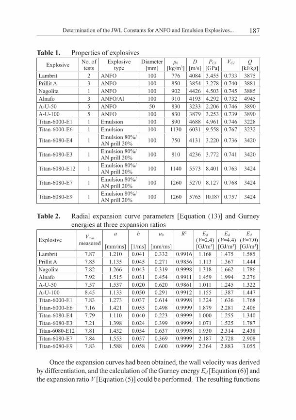
187Determination of the JWL Constants for ANFO and Emulsion Explosives...
Table 1. Properties of explosives
Explosive No. oftests
Explosivetype
Diameter[mm]
ρ0
[kg/m3]D
[m/s]PCJ
[GPa]VCJ Q
[kJ/kg]Lambrit 2 ANFO 100 776 4084 3.455 0.733 3875Prillit A 3 ANFO 100 850 3854 3.278 0.740 3881Nagolita 1 ANFO 100 902 4426 4.503 0.745 3885Alnafo 3 ANFO/Al 100 910 4193 4.292 0.732 4945A-U-50 5 ANFO 50 830 3233 2.206 0.746 3890A-U-100 5 ANFO 100 830 3879 3.253 0.739 3890Titan-6000-E1 1 Emulsion 100 890 4688 4.961 0.746 3228Titan-6000-E6 1 Emulsion 100 1130 6031 9.558 0.767 3232
Titan-6080-E4 1 Emulsion 80%/AN prill 20% 100 750 4131 3.220 0.736 3420
Titan-6080-E3 1 Emulsion 80%/AN prill 20% 100 810 4236 3.772 0.741 3420
Titan-6080-E12 1 Emulsion 80%/AN prill 20% 100 1140 5573 8.401 0.763 3424
Titan-6080-E7 1 Emulsion 80%/AN prill 20% 100 1260 5270 8.127 0.768 3424
Titan-6080-E9 1 Emulsion 80%/AN prill 20% 100 1260 5765 10.187 0.757 3424
Table 2. Radial expansion curve parameters [Equation (13)] and Gurney energies at three expansion ratios
Explosive Vmax measured
a
[mm/ms]
b
[1/ms]
u0
[mm/ms]
R2 Ed
(V=2.4)[GJ/m3]
Ed
(V=4.4)[GJ/m3]
Ed
(V=7.0)[GJ/m3]
Lambrit 7.87 1.210 0.041 0.332 0.9916 1.168 1.475 1.585Prillit A 7.85 1.135 0.045 0.271 0.9856 1.113 1.367 1.444Nagolita 7.82 1.266 0.043 0.319 0.9998 1.318 1.662 1.786Alnafo 7.92 1.515 0.031 0.454 0.9911 1.459 1.994 2.276A-U-50 7.57 1.537 0.020 0.620 0.9861 1.011 1.245 1.322A-U-100 8.45 1.133 0.050 0.291 0.9912 1.155 1.387 1.447Titan-6000-E1 7.83 1.273 0.037 0.614 0.9998 1.324 1.636 1.768Titan-6000-E6 7.16 1.421 0.055 0.498 0.9999 1.879 2.281 2.406Titan-6080-E4 7.79 1.110 0.040 0.223 0.9999 1.000 1.255 1.340Titan-6080-E3 7.21 1.398 0.024 0.399 0.9999 1.071 1.525 1.787Titan-6080-E12 7.81 1.432 0.054 0.637 0.9998 1.930 2.314 2.438Titan-6080-E7 7.84 1.553 0.057 0.369 0.9999 2.187 2.728 2.908Titan-6080-E9 7.83 1.588 0.058 0.600 0.9999 2.364 2.883 3.055
Once the expansion curves had been obtained, the wall velocity was derived by differentiation, and the calculation of the Gurney energy Ed [Equation (6)] and the expansion ratio V [Equation (5)] could be performed. The resulting functions
188 J.A. Sanchidrián, R. Castedo, L.M. López, P. Segarra, A.P. Santos
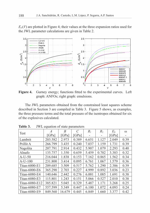
Ed (V) are plotted in Figure 4; their values at the three expansion ratios used for the JWL parameter calculations are given in Table 2.
Figure 4. Gurney energy; functions fitted to the experimental curves. Left graph: ANFOs; right graph: emulsions.
The JWL parameters obtained from the constrained least squares scheme described in Section 3 are compiled in Table 3. Figure 5 shows, as examples, the three pressure terms and the total pressure of the isentropes obtained for six of the explosives calculated.
Table 3. JWL equation of state parameters
Test A[GPa]
B[GPa]
C[GPa]
R1-
R2-
E0[GPa]
ω-
Lambrit 203.582 2.973 0.389 6.651 1.127 2.049 0.39Prillit A 266.799 3.435 0.240 7.037 1.159 1.731 0.39Nagolita 207.791 2.914 0.432 5.907 1.079 2.293 0.40Alnafo 135.757 1.350 0.659 5.459 0.702 3.383 0.32A-U-50 216.044 1.838 0.153 7.162 0.865 1.562 0.34A-U-100 231.800 3.414 0.095 6.761 1.067 1.579 0.36Titan-6000-E1 209.685 3.509 0.517 5.762 1.290 2.386 0.39Titan-6000-E6 365.290 2.703 0.227 4.999 0.892 3.036 0.23Titan-6080-E4 140.646 2.442 0.276 6.001 1.085 1.691 0.38Titan-6080-E3 115.801 1.243 0.151 5.066 0.527 2.010 0.38Titan-6080-E12 385.821 5.045 0.329 5.487 1.171 3.268 0.25Titan-6080-E7 557.599 5.349 0.447 6.100 1.072 4.093 0.24Titan-6080-E9 849.560 16.679 0.445 6.849 1.660 3.377 0.42
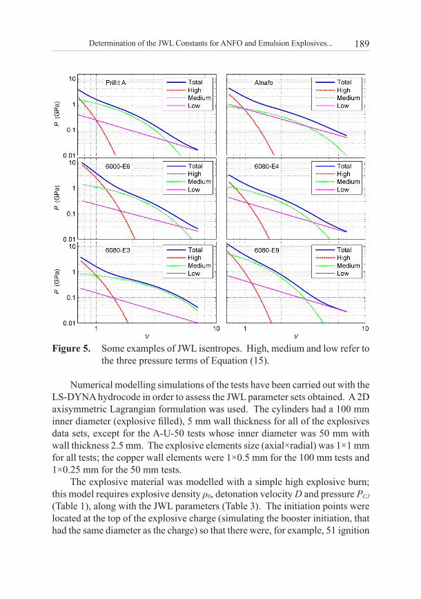
189Determination of the JWL Constants for ANFO and Emulsion Explosives...
Figure 5. Some examples of JWL isentropes. High, medium and low refer to the three pressure terms of Equation (15).
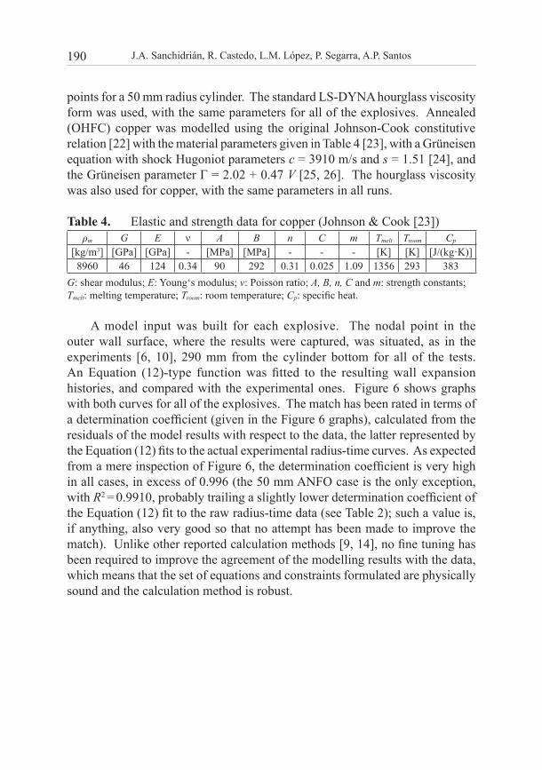
Numerical modelling simulations of the tests have been carried out with the LS-DYNA hydrocode in order to assess the JWL parameter sets obtained. A 2D axisymmetric Lagrangian formulation was used. The cylinders had a 100 mm inner diameter (explosive filled), 5 mm wall thickness for all of the explosives data sets, except for the A-U-50 tests whose inner diameter was 50 mm with wall thickness 2.5 mm. The explosive elements size (axial×radial) was 1×1 mm for all tests; the copper wall elements were 1×0.5 mm for the 100 mm tests and 1×0.25 mm for the 50 mm tests.
The explosive material was modelled with a simple high explosive burn; this model requires explosive density ρ0, detonation velocity D and pressure PCJ (Table 1), along with the JWL parameters (Table 3). The initiation points were located at the top of the explosive charge (simulating the booster initiation, that had the same diameter as the charge) so that there were, for example, 51 ignition
190 J.A. Sanchidrián, R. Castedo, L.M. López, P. Segarra, A.P. Santos
points for a 50 mm radius cylinder. The standard LS-DYNA hourglass viscosity form was used, with the same parameters for all of the explosives. Annealed (OHFC) copper was modelled using the original Johnson-Cook constitutive relation [22] with the material parameters given in Table 4 [23], with a Grüneisen equation with shock Hugoniot parameters c = 3910 m/s and s = 1.51 [24], and the Grüneisen parameter Γ = 2.02 + 0.47 V [25, 26]. The hourglass viscosity was also used for copper, with the same parameters in all runs.
Table 4. Elastic and strength data for copper (Johnson & Cook [23])ρm G E ν A B n C m Tmelt Troom Cp
[kg/m3] [GPa] [GPa] - [MPa] [MPa] - - - [K] [K] [J/(kg·K)]8960 46 124 0.34 90 292 0.31 0.025 1.09 1356 293 383
G: shear modulus; E: Young‘s modulus; ν: Poisson ratio; A, B, n, C and m: strength constants; Tmelt: melting temperature; Troom: room temperature; Cp: specific heat.
A model input was built for each explosive. The nodal point in the outer wall surface, where the results were captured, was situated, as in the experiments [6, 10], 290 mm from the cylinder bottom for all of the tests. An Equation (12)-type function was fitted to the resulting wall expansion histories, and compared with the experimental ones. Figure 6 shows graphs with both curves for all of the explosives. The match has been rated in terms of a determination coefficient (given in the Figure 6 graphs), calculated from the residuals of the model results with respect to the data, the latter represented by the Equation (12) fits to the actual experimental radius-time curves. As expected from a mere inspection of Figure 6, the determination coefficient is very high in all cases, in excess of 0.996 (the 50 mm ANFO case is the only exception, with R2 = 0.9910, probably trailing a slightly lower determination coefficient of the Equation (12) fit to the raw radius-time data (see Table 2); such a value is, if anything, also very good so that no attempt has been made to improve the match). Unlike other reported calculation methods [9, 14], no fine tuning has been required to improve the agreement of the modelling results with the data, which means that the set of equations and constraints formulated are physically sound and the calculation method is robust.
191Determination of the JWL Constants for ANFO and Emulsion Explosives...
Figure 6. Wall expansion histories. Comparison of experimental data and modelled values.
5 Conclusions
The Gurney’s expansion energy density in the cylinder test was revisited using the conical relative expansion volume of Souers et al. [14, 17, 18]; a newly formulated function fitting the wall expansion radius history data was proposed, with a non-zero initial velocity, which makes the calculated expansion energy positive at a relative volume V = 1 [14].
192 J.A. Sanchidrián, R. Castedo, L.M. López, P. Segarra, A.P. Santos
Six equations were established to determine the JWL equation of state parameters A, B, C, R1, R2, E0: three of them refer to the CJ state and the other three represent the Gurney expansion energies at three expansion stages, which are made equal to the values determined from the cylinder test measurements. The non-linear system was solved by a least-squares scheme; constraints on the unknowns were imposed to comply with their physical meaning. The constant ω was obtained by a thermodynamic calculation at large expansions.
JWL parameters have been obtained in this manner for thirteen explosives of the ANFO and emulsion types, of different densities and detonation velocities and, in one case, tested at two diameters. The resulting parameter sets have been assessed by numerical modelling of the tests with the LS-DYNA code. The calculated cylinder wall expansion histories have been compared with the experimental ones; the agreement was outstanding, to the point that no fine-tuning of the parameters was found to be required. This confirms that the set of conditions, the constraints on the parameters, and the least squares calculation used, constitute a robust methodology that fully captures the physics of the expansion of the detonation products involved in the cylinder test. The JWL parameter sets obtained may be used for numerical modelling calculations in mining, civil and safety engineering applications involving explosives of the ANFO and emulsion types, with a wide range of densities, detonation velocities and energies.
AcknowledgementsThis work has been partially funded by the Government of Spain, project No. IPT-2012-0845-370000, and by MAXAM Civil Explosives, whose support is gratefully acknowledged.
6 References
[1] Lee E.L., Hornig H.C., Kury J.W., Adiabatic Expansion of High Explosive Detonation Products, Report UCRL-50422, University of California, Lawrence Radiation Laboratory, Livermore, CA, USA, 1968.
[2] Souers P.C., Wu B., Haselman Jr. L.C., Detonation Equation of State at LLNL, 1995, Report UCRL-ID-119262 Rev. 3, Lawrence Livermore National Laboratory, Livermore, CA, USA, 1996.
[3] Penn L., Helm F., Finger M., Lee E., Determination of Equation-of-state Parameters for Four Types of Explosive, Report UCRL-51892, Lawrence Livermore Laboratory, Livermore, CA, USA, 1975.
[4] Helm F., Finger M., Hayes B., Lee E., Cheung H., Walton J., High Explosive
193Determination of the JWL Constants for ANFO and Emulsion Explosives...
Characterization for the Dice Throw Event, Report UCRL-52042, Lawrence Livermore Laboratory, Livermore, CA, USA, 1976.
[5] Davis L.L., Hill L.G., ANFO Cylinder Tests, Shock Compression Condens. Matter − 2001, Proc. Am. Phys. Soc. Top. Conf., 2002, 620, 165-168.
[6] Nyberg U., Arvanitidis I., Ouchterlony F., Olsson M., Cylinder Expansion Tests on Reference Explosives from Production, Technical Report No. 21/Deliverable 5-4. EU Project GRD-2000 – 25224 Less Fines, SveBeFo, Stockholm, Sweden, 2002.
[7] Nyberg U., Arvanitidis I., Olsson M., Ouchterlony F., Large Size Cylinder Expansion Tests on ANFO and Gassed Bulk Emulsion Explosives, 2nd World Conf. Expl. Blast. Tech., Prague (Holmberg R., Ed.), Taylor & Francis, Lisse, The Netherlands, 2003, 181-191.
[8] Esen S., Nyberg U., Arai H., Ouchterlony F., Determination of the Energetic Characteristics of Commercial Explosives Using the Cylinder Expansion Test Technique, Swedish Blasting Research Centre and Luleå Tekniska Universitet, Stockholm and Luleå, Sweden, 2005.
[9] Hansson H., Determination of Properties for Emulsion Explosives Using Cylinder Expansion Tests and Numerical Simulation, Swebrec Report 2009:1, Stockholm and Luleå, Sweden, 2009.
[10] López L.M., Sanchidrián J.A., Segarra P., Ortega M.F., Evaluation of ANFO Performance with Cylinder Test, 10th Int. Symp. Rock Frag. Blast. – Fragblast 10, New Delhi, India, (Singh P.K., Sinha A., Eds.), CRC Press, 2013, 579-586.
[11] Hamashima H., Kato Y., Itoh S., Determination of JWL Parameters for Non-ideal Explosive, Shock Compression Condens. Matter − 2003, Proc. Am. Phys. Soc. Top. Conf., 2004, 706, 331-334.
[12] Otsuka M., Tanaka S., Itoh S., Research for Explosion of High Explosive in Complex Media, in: Computational Methods, (Liu G.R., Tan V.B.C., Han X., Eds.), Springer, Dordrecht, The Netherlands, 2006, pp. 1885-1890.
[13] Merchant P.W., White S.J., Collyer A.M., A WBL-consistent JWL Equation of State for the HMX-based Explosive EDC37 from Cylinder Tests, 12th Int. Det. Symp., Naval Surface Warfare Center, Maryland, USA, 2002.
[14] Souers P.C., JWL Calculating, Report UCRL-TR-211984, Lawrence Livermore National Laboratory, Livermore, CA, USA, 2005.
[15] Dobratz B.M., Crawford P.C., LLNL Explosives Handbook, Properties of Chemical Explosives and Explosive Simulants, Report UCRL-52997 Change 2, University of California, Lawrence Livermore National Laboratory, Livermore, CA, USA, 1985.
[16] Reaugh J.E., Souers P.C., A Constant-density Gurney Approach to the Cylinder Test, Propellants Explos. Pyrotech., 2004, 29(2), 124-128.
[17] Souers P.C., Garza R., Hornig H., Lauderbach L., Owens C., Vitello P., Metal Angle Correction in the Cylinder Test, Propellants Explos. Pyrotech., 2011, 36(1), 9-15.
[18] Souers P.C., Lauderbach L., Garza R., Ferranti L., Vitello P., Upgraded Analytical Model of the Cylinder Test, Propellants Explos. Pyrotech., 2013, 38(3), 419-424.
[19] Hornberg H., Volk F., The Cylinder Test in the Context of Physical Detonation Measurement Methods, Propellants Explos. Pyrotech., 1989, 14(5), 199-211.
194 J.A. Sanchidrián, R. Castedo, L.M. López, P. Segarra, A.P. Santos
[20] Sanchidrián J.A., López L.M., Calculation of the Energy of Explosives with a Partial Reaction Model. Comparison with Cylinder Test Data, Propellants Explos. Pyrotech., 2006, 31(1), 25-32.
[21] Moser P., Less Fines Production in Aggregate and Industrial Minerals Industry, 2nd World Conference on Explosives and Blasting Technique, Prague, (Holmberg R., Ed.), Taylor & Francis, Lisse, The Netherlands, 2003, pp. 335-343.
[22] Johnson G.R., Cook W.H., A Constitutive Model and Data for Metals Subjected to Large Strains, High Strain Rates and High Temperatures, 7th Int. Symp. on Ballistics, The Hague, The Netherlands, 1983, pp. 541-547.
[23] Johnson G.R., Cook W.H., Fracture Characteristics of Three Metals Subjected to Various Strains, Strain Rates, Temperatures and Pressures, J. Eng. Fract. Mech., 1985, 21(1), 31-48.
[24] Marsh S.P., LASL Shock Hugoniot Data ,Vol. 5, University of California Press, 1980. [25] Steinberg D.J., Equation of State and Strength Properties of Selected Materials,
Report UCRL-MA-106439, Lawrence Livermore National Laboratory, Livermore, CA, USA, 1991.
[26] Vignjevic R., Campbell J.C., Bourne N.K., Djordjevic N., Modeling Shock Waves in Orthotropic Elastic Materials, J. Appl. Phys., 2008, 104(4), 044904.