Embed Size (px)
Citation preview
International Research Journal of Engineering and Technology (IRJET) e-ISSN: 2395 -0056
Volume: 03 Issue: 11 | Nov -2016 www.irjet.net p-ISSN: 2395-0072
© 2016, IRJET | Impact Factor value: 4.45 | ISO 9001:2008 Certified Journal | Page 975
DETERMINATION OF TRUE BENDING STRESS IN SPUR GEARS
Mr. Kailas S. Pathade1, Prof. Santosh MaliPatil2
1M.Tech Student Department of Mechanical Engineering, Maratha Mandal Engineering College,
Belagavi-590018, Karnataka, India
2Professor Department of Mechanical Engineering, Maratha Mandal Engineering College,
Belagavi-590018, Karnataka, India ---------------------------------------------------------------------***---------------------------------------------------------------------
Abstract - This paper presents the work carried regarding the determination of true bending stresses in spur gears. Gearing is one of the most critical components in a mechanical power transmission system and the true bending stresses at the tooth root of spur gears are quite different from the nominal values. The three dimensional model of set of spur gear was prepared using ‘KISSsoft’ software. The step (.stp) files were imported to ‘ANSYS workbench 14.5’ software. Loads were applied in the form of torque on the spur gear. The results of bending stress obtained by ‘ANSYS workbench 14.5’ are in well agreement with those obtained by analytical method and KISSsoft results. Keeping the load of the gear constant the analysis is repeated for various tooth thicknesses of the gears. The analytical results, KISSsoft results and ansys results are compared and the effect of facewidth is on true stress determined.
Keywords- True bending stress, Nominal value, Bending stress, KISSsoft, ANSYS workbench 14.5.
1. INTRODUCTION
Gears are utilized to carry power starting from driver shaft then onto the driven when they are separated by narrow distance. They keep up steady speed proportion overcoming slip. Helical, Spur, rack and pinion type, worm and worm wheel, bevel, etc. Gears having teeth lateral to axis are spur gears most accepted, because they made effortlessly also equipped for sustaining typical loading conditions and useful for small speeds.
Gears are important amongst wide basic segments in force transfer mechanism, also in maximum modern rotating apparatus. We can consider that gear will prevail as best method for transmitting power in future machines because of their high level quality of power transmission and smallness [1].
1.1 BENDING STREESES IN GEARS
There are a few types of fracture modes in spur gears, and one of the fundamental or important type of facture modes is ‘Bending failure’ of the teeth. The bending stresses are another interesting issue in a spur gear. When a load is maximum, bending failure will take place. In gears
bending failure is anticipated by correlating the numerically determined to practically calculate permissible fatigue standards of assumed material. The equation for bending stress got using Lewis expression. In gear tooth catastrophic failure or yielding is due to extreme bending stress that’s why it is one of essential gear design concept [2].
1.2 TRUE BENDING STRESS
The true bending stresses at root of tooth in a spur gears is not same as that of the supposed or theoretical values that are used for the determining the load capacity of spur gear, either by principals or common designing laws. No issues emerge in utilizing a weight holding strength while standards correlated along the outcomes of fatigue tests on bending for which cutoff points determined along similar simplified technics. In any case, at tooth root true stress has dissimilar pattern plus standards, plus the creator need to know this dissimilar pattern, particularly considering portable gears along small ribs plus rims [3].
2. PROBLEM DEFINITION
The stress will determined using a 3-D finite element solid model for spur gears. The study will determine bending stress with tooth thickness using given geometry condition also by changing tooth thickness.
Figure 1 Gearing Arrangement of the problem considered Table- 1: Specification of Gears

International Research Journal of Engineering and Technology (IRJET) e-ISSN: 2395 -0056
Volume: 03 Issue: 11 | Nov -2016 www.irjet.net p-ISSN: 2395-0072
© 2016, IRJET | Impact Factor value: 4.45 | ISO 9001:2008 Certified Journal | Page 976
Gear Speed Rpm Teeth Nos. P.C.D. mm
Gear No.1 n1 750 Z1 50 d1 150
Gear No.2 n2 397 Z2 80 d2 240
As both the pinion & gear are made of same material, pinion is weaker. So the stress analysis of the pinion is carried out.
Parameters: Motor Power (P) = 15 HP (8 Pole, Speed 750 Rpm) Module (m) = 3 mm Material: 18CrNiMo7-6, is used for both gears and the properties are as follow. Table- 3: Material Properties
Density g/cm3 7.86 g/cm3
Young’s Modulus (MPa) 210000 MPa
Tensile Strength (Yield) MPa 786 MPa
Poisson’s Ratio 0.3
2.1 ANALYTICAL SOLUTION
The tangent force is main cause for bending stress, and that one is calculated as below.
The forces in Gear 1 and gear 2 are determined using following method.
Ft = P/V where, Ft is tangent force (N) P is power (W) Mt Toque in (N/m) V is velocity (m/s) Power = 15 x 746 = 11190 W V = (π d1 n1)/60 V = 5.89 m/s Ft = 11190/5.89 Ft = 1899.83 N Mt = Ft x r1 = 1899.83 x 0.075 Mt = 142.417 N/m
The Actual Bending Stress is found from AGMA equation [4]: σ = Ft/ (b*m*j) Kv K0 Km Where, σ = 1900/ (20 x 3 x 0.45778) x 1.4x1x1.3 = 125.8862 MPa
Table- 2: Bending stress for different Face width
Face width of Gear in mm Bending Stress MPa
20 125.8862
25 100.7089
30 83.92412
35 71.93496
40 62.94309
2.2 BENDING STRESS CALCULATIONS USING KISSsoft KISSsoft is outline programming for engineers and creators utilized as a part of a wide assortment of fields: like assembling link auto frameworks, gears for development hardware, Formula 1 race auto transmissions or the minor gears utilized as a part of Mars rovers, more organizations everywhere throughout the world have come to depend on KISSsoft plan programming.
Naturally all important geometry calculations are also executed, reference dimensions are provided for manufacturing, and tooth form is determined in two and three dimensions [5].
Table- 3: Bending stress for different Face width using KISSsoft
Face width of Gear in mm Bending Stress MPa
20 133.71
25 106.96
30 89.14
35 76.40
40 61.28
2.3 BENDING STRESS CALCULATIONS USING FEA
Numbers of issues in engineering and applied science are connected by differential or integral equations. The answer for these conditions would give an exact and close solution to these conditions to the specific issue being studied. In any case, complexities in geometry and in boundary conditions that are seen in most genuine world problems that means an exact solution cannot be calculated or calculated in real amount of time. However, current product design process durations infer that engineers must acquire design solutions in a short measure of time. They are satisfied to acquire approximate solutions that can be promptly gotten in a sensible time period, and with sensible effort. The Finite Element Method is one such approximate solution technique. “The Finite Element Method is a

International Research Journal of Engineering and Technology (IRJET) e-ISSN: 2395 -0056
Volume: 03 Issue: 11 | Nov -2016 www.irjet.net p-ISSN: 2395-0072
© 2016, IRJET | Impact Factor value: 4.45 | ISO 9001:2008 Certified Journal | Page 977
numerical technique getting estimated answers for some issues experienced in designing analysis”.
The Workbench 14.5 software is the foundation on which the all organizations wide spacious and most profound software that has latest simulation technique. A creative project perspective holds complete simulation flowchart, directing designer in difficult multiphasic analyses by only copy-import technique. Using two-directional CAD connection, with auto project update system, the ANSYS Workbench Platform conveys exceptional profitability, empowering reproduction driven item improvement [6].
METHODOLOGY
Procedure:
First of all, we have prepared gear pair in KISSsoft for spur gear and save as this part as step file (.stp) for Exporting into ANSYS workbench. Import step file in ANSYS workbench simulation module. Apply material for spur gear (18CrNiMo7-6). Then we applied frictional support for both and torque of 142.417 N-m for driver.
FEA RESULTS FOR SPUR GEARS:
Figure 2 Equivalent Von Misses Stress for face width 20 mm
Figure 3 Equivalent Von Misses Stress for face width 25 mm
Figure 4 Equivalent Von Misses Stress for face width 30 mm
Figure 5 Equivalent Von Misses Stress for face width 35 mm
Figure 6 Equivalent Von Misses Stress for face width 40 mm
3. EFFECT OF FACE WIDTH:
The results of Maximum Stress obtained for various thicknesses are tabulate below. As load per unit thickness is kept constant, the maximum stress is almost same for all gears.
International Research Journal of Engineering and Technology (IRJET) e-ISSN: 2395 -0056
Volume: 03 Issue: 11 | Nov -2016 www.irjet.net p-ISSN: 2395-0072
© 2016, IRJET | Impact Factor value: 4.45 | ISO 9001:2008 Certified Journal | Page 978
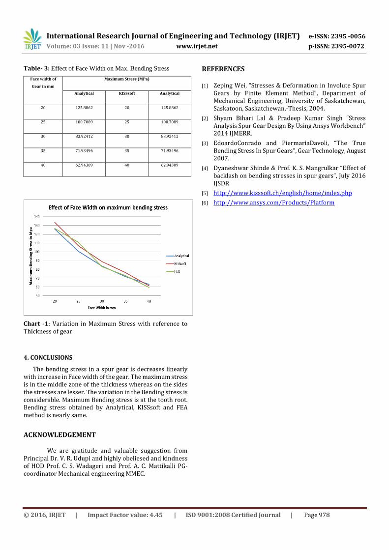
Table- 3: Effect of Face Width on Max. Bending Stress
Face width of
Gear in mm
Maximum Stress (MPa)
Analytical KISSsoft Analytical
20 125.8862 20 125.8862
25 100.7089 25 100.7089
30 83.92412 30 83.92412
35 71.93496 35 71.93496
40 62.94309 40 62.94309
Chart -1: Variation in Maximum Stress with reference to Thickness of gear
4. CONCLUSIONS
The bending stress in a spur gear is decreases linearly with increase in Face width of the gear. The maximum stress is in the middle zone of the thickness whereas on the sides the stresses are lesser. The variation in the Bending stress is considerable. Maximum Bending stress is at the tooth root. Bending stress obtained by Analytical, KISSsoft and FEA method is nearly same.
ACKNOWLEDGEMENT
We are gratitude and valuable suggestion from Principal Dr. V. R. Udupi and highly obeliesed and kindness of HOD Prof. C. S. Wadageri and Prof. A. C. Mattikalli PG-coordinator Mechanical engineering MMEC.
REFERENCES [1] Zeping Wei, “Stresses & Deformation in Involute Spur
Gears by Finite Element Method”, Department of Mechanical Engineering, University of Saskatchewan, Saskatoon, Saskatchewan,-Thesis, 2004.
[2] Shyam Bihari Lal & Pradeep Kumar Singh “Stress Analysis Spur Gear Design By Using Ansys Workbench” 2014 IJMERR.
[3] EdoardoConrado and PiermariaDavoli, “The True Bending Stress In Spur Gears”, Gear Technology, August 2007.
[4] Dyaneshwar Shinde & Prof. K. S. Mangrulkar “Effect of backlash on bending stresses in spur gears”, July 2016 IJSDR
[5] http://www.kisssoft.ch/english/home/index.php
[6] http://www.ansys.com/Products/Platform
![· (MOE) in bending in EN 338:2003 [13]. There is variety of different measurement tech- niques for determination of timber strength class properties](https://img.pdfslide.net/doc/110x75/5c6603d909d3f2e4308b9c61/-moe-in-bending-in-en-3382003-13-there-is-variety-of-different-measurement.jpg)
![UNIVERSITY OF THE BASQUE COUNTRY DETERMINATION OF TRANSVERSE COMPRESSIVE STRENGTH OF LONG FIBER COMPOSITES BY THREE-POINT BENDING OF [90m/0n] LAMINATED](https://img.pdfslide.net/doc/110x75/56649d2e5503460f94a05143/university-of-the-basque-country-determination-of-transverse-compressive-strength.jpg)