Embed Size (px)
Citation preview
INSTALLATION GUIDEEN
GLISHDEUTSCH
ITALIANO
ESPAÑO
LFRAN
ÇAIS
AXIS P3353 Network Camera
AXIS P3354 Network Camera
AXIS P3363-V Network Camera
AXIS P3364-V Network Camera
AXIS P3364-LV Network Camera
About this DocumentThis document includes instructions for installing the AXIS P3353/P3354/P3363-V/P3364-V/P3364-LV on your network. Previous experience of networking will be beneficial when installing the product.Legal ConsiderationsVideo and audio surveillance can be prohibited by laws that vary from country to country. Check the laws in your local region before using this product for surveillance purposes. This product includes one (1) H.264 decoder license. To purchase further licenses, contact your reseller.Trademark AcknowledgementsApple, Boa, Bonjour, Ethernet, Internet Explorer, Linux,Microsoft, Mozilla, Real, SMPTE, QuickTime, UNIX, Windows,Windows Vista and WWW are registered trademarks of therespective holders. Java and all Java-based trademarks andlogos are trademarks or registered trademarks of Oracleand/or its affiliates. UPnPTM is a certification mark of theUPnPTM Implementers Corporation.Electromagnetic Compatibility (EMC)This equipment has been designed and tested to fulfill applicable standards for:• Radio frequency emission when installed according to the
instructions and used in its intended environment.• Immunity to electrical and electromagnetic phenomena when
installed according to the instructions and used in its intended environment.
USA - This equipment has been tested using a shielded network cable (STP) and found to comply with the limits for a Class B digital device, pursuant to part 15 of the FCC Rules. These limits are designed to provide reasonable protection against harmful interference in a residential installation. This equipment generates, uses and can radiate radio frequency energy and, if not installed and used in accordance with the instructions, may cause harmful interference to radio communications. However, there is no guarantee that interference will not occur in a particular installation. If this equipment does cause harmful interference to radio or television reception, which can be determined by turning the equipment off and on, the user is encouraged to try to correct the interference by one or more of the following measures: • Reorient or relocate the receiving antenna.• Increase the separation between the equipment and
receiver.• Connect the equipment into an outlet on a circuit
different from that to which the receiver is connected.• Consult the dealer or an experienced radio/TV technician
for help.
Canada - This Class B digital apparatus complies with Canadian ICES-003.
Europe - This digital equipment fulfills the requirements for RF emission according to the Class B limit of EN 55022.
This product fulfills the requirements for immunity according to EN 61000-6-1 residential, commercial and light-industry environments.This product fulfills the requirements for immunity according to EN 61000-6-2 industrial environments.This product fulfills the requirements for immunity according to EN 55024 office and commercial environments.
Australia - This digital equipment fulfills the requirements for RF emission according to the Class B limit of AS/NZS CISPR 22.Korea -
SafetyThis product complies with EN/IEC/UL 60950-1, Safety ofInformation Technology Equipment.Equipment Modifications This equipment must be installed and used in strict accordance with the instructions given in the user documentation. This equipment contains no user-serviceable components. Unauthorized equipment changes or modifications will invalidate all applicable regulatory certifications and approvals. LiabilityEvery care has been taken in the preparation of this document. Please inform your local Axis office of any inaccuracies or omissions. Axis Communications AB cannot be held responsible for any technical or typographical errors and reserves the right to make changes to the product and documentation without prior notice. Axis Communications AB makes no warranty of any kind with regard to the material contained within this document, including, but not limited to, the implied warranties of merchantability and fitness for a particular purpose. Axis Communications AB shall not be liable nor responsible for incidental or consequential damages in connection with the furnishing, performance or use of this material.RoHSThis product complies with both the European RoHS directive, 2002/95/EC, and the Chinese RoHS regulations, ACPEIP.WEEE DirectiveThe European Union has enacted a Directive 2002/96/EC on Waste Electrical and Electronic Equipment (WEEE Directive). This directive is applicable in the European Union member states.The WEEE marking on this product (see right) or its documentation indicates that the product must not be disposed of together with household waste. To prevent possible harm to human health and/or the environment, the product must be disposed of in an approved and environmentally safe recycling process. For further information on how to dispose of this product correctly, contact the product supplier, or the local authority responsible for waste disposal in your area. Business users should contact the product supplier for information on how to dispose of this product correctly. This product should not be mixed with other commercial waste. For more information, visit www.axis.com/techsup/commercial wasteSupportShould you require any technical assistance, please contact your Axis reseller. If your questions cannot be answered immediately, your reseller will forward your queries through the appropriate channels to ensure a rapid response. If you are connected to the Internet, you can:• download user documentation and firmware updates• find answers to resolved problems in the FAQ database. Search
by product, category, or phrases• report problems to Axis support by logging in to your private
support area.Contact InformationAxis Communications ABEmdalavägen 14223 69 Lund SwedenTel: +46 46 272 18 00Fax: +46 46 13 61 30www.axis.com
Japan - この装置は、クラスB 情報技術装置です。この装置は、家庭環境で使用することを目 的としていますが、この装置がラジオやテレビジョン受信機に近接して使用されると、 受信障害を引き起こすことがあります。 取扱説明書に従って正しい取り扱いをして下さい。

ENGLISH
SafeguardsPlease read through this Installation Guide carefully before installing the Axis product. Keep the Installation Guide for further reference.
• Store the Axis product in a dry and ventilated environment.
• Avoid exposing the Axis product to vibration, shocks or heavy pressure. Do not install the product on unstable brackets, unstable or vibrating surfaces or walls, since this could cause damage to the product.
• Only use applicable tools when installing the Axis product; excessive force could cause damage to the product.
• Do not use chemicals, caustic agents, or aerosol cleaners. Use a damp cloth for cleaning.
• Use only accessories that comply with technical specification of the product. These can be provided by Axis or a third party.
• Use only spare parts provided by or recommended by Axis.
• Do not attempt to repair the product by yourself, contact Axis or your Axis reseller for ser-vice matters.
• This Axis product shall be used in compliance with local laws and regulations.
• To use this Axis product outdoors, it shall be installed in an approved outdoor housing.
• The Axis product should be installed by a trained professional. Observe relevant national and local regulations for the installation.
Transportation
• When transporting the Axis product, use the original packaging or equivalent to prevent damage to the product.
Battery ReplacementThis Axis product uses a 3.0 V CR2032 lithium battery as the power supply for its internal real-time clock (RTC). Under normal conditions this battery will last for a minimum of 5 years. Low battery power affects the operation of the RTC, causing it to reset at every power-up. A log message will appear when the battery needs replacing. The battery should not be replaced unless required!
If the battery does need replacing, please contact www.axis.com/techsup for assistance.
• Dispose of used batteries according to the manufacturer's instructions.
• Risk of explosion if battery is incorrectly replaced.
• Replace only with the same or equivalent battery, as recommended by the manufacturer.
Dome Cover Cleaning
• Be careful not to scratch or damage the dome cover. Keep the protective plastic on the dome cover until the installation is complete. Do not clean a dome cover that looks clean to the eye and never polish the surface. Excessive cleaning could damage the surface.
• For general cleaning of a dome cover it is recommended to use a non-abrasive, solvent-free neutral soap or detergent with water and a soft cloth. Rinse well with clean lukewarm water. Dry with a soft cloth to prevent water spotting.
• Never use harsh detergents, gasoline, benzene or acetone etc. and avoid cleaning in direct sunlight or at elevated temperatures.
• Domes for L products come with an anti-scratch surface. Avoid leaving finger prints on the dome surface since this might impair image quality.
AXIS P33 Network Camera Installation Guide Page 5
ENGLISH
AXIS P33 Network Camera Installation GuideThis installation guide provides instructions for installing an AXIS P3353/P3354/P3363-V/P3364-V/P3364-LV Network Camera on your network. For all other aspects of using the product, please see the User Manual, available on www.axis.com
Notes:• Before you begin, make sure that the package contents, the required cables, tools,
and documentation are available. See Package contents below.• This network camera is intended to operate with PoE; if not available use AXIS PoE Midspan 1 port (not
included).
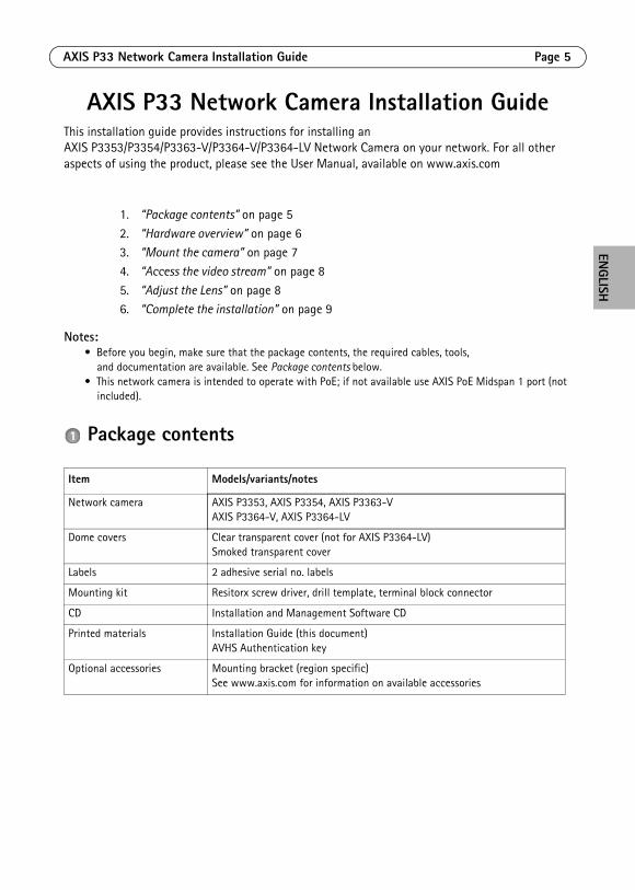
Package contents
1. “Package contents” on page 5
2. “Hardware overview” on page 63. “Mount the camera” on page 7
4. “Access the video stream” on page 8
5. “Adjust the Lens” on page 86. “Complete the installation” on page 9
Item Models/variants/notes
Network camera AXIS P3353, AXIS P3354, AXIS P3363-VAXIS P3364-V, AXIS P3364-LV
Dome covers Clear transparent cover (not for AXIS P3364-LV)Smoked transparent cover
Labels 2 adhesive serial no. labels
Mounting kit Resitorx screw driver, drill template, terminal block connector
CD Installation and Management Software CD
Printed materials Installation Guide (this document)AVHS Authentication key
Optional accessories Mounting bracket (region specific)See www.axis.com for information on available accessories
Page 6 AXIS P33 Network Camera Installation Guide
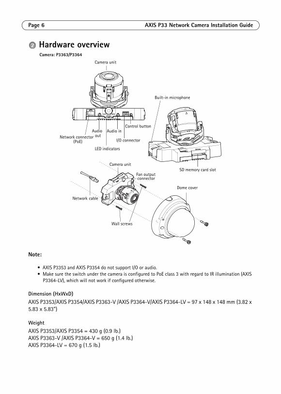
Hardware overview
Note:
• AXIS P3353 and AXIS P3354 do not support I/O or audio.• Make sure the switch under the camera is configured to PoE class 3 with regard to IR illumination (AXIS
P3364-LV), which will not work if configured otherwise.
Dimension (HxWxD)AXIS P3353/AXIS P3354/AXIS P3363-V /AXIS P3364-V/AXIS P3364-LV = 97 x 148 x 148 mm (3.82 x 5.83 x 5.83")
WeightAXIS P3353/AXIS P3354 = 430 g (0.9 lb.)AXIS P3363-V /AXIS P3364-V = 650 g (1.4 lb.)AXIS P3364-LV = 670 g (1.5 lb.)
Network connector
LED indicators
I/O connector(PoE)
Camera unit
Network cable
Dome cover
outAudio in
SD memory card slot
Wall screws
Audio
Camera unit
Fan output connector
Built-in microphone
Control button
Camera: P3363/P3364

AXIS P33 Network Camera Installation Guide Page 7
ENGLISH
Mount the cameraThis Axis product can be mounted with the cables routed through or along the wall. This product can also be fitted with a metal conduit for protecting the cabling when they are routed along the wall. See the illustration that follows.
Mount camera directly onto the wall1. Using the drill template drill 2 holes in the wall.2. Route and connect the network cable.
3. Attach the camera unit to the wall using screws and plugs appropriate for the wall material.
Mount camera using a mounting bracket (not included)1. Using the drill template drill 2 holes in the wall.
2. Route the network cable through the wall and through the holes in the mounting bracket.
3. Attach the mounting bracket to the wall, using screws and plugs appropriate for the wall material.
4. Connect the network cable.5. Optionally connect the I/O and audio cables; see page 10 for details.
6. Optionally insert the SD memory card.
7. Attach the camera unit to the mounting bracket using two appropriate screws.Note:
• These instructions are for mounting the camera on a wall. The mounting bracket can also be used for mounting the network camera to a junction box.
• AXIS P3353 and AXIS P3354 do not support audio and I/O.
Metal conduit (Optional/not included)
Mounting bracket (Optional/not included)
Network cable
M4x8 screw
Wall screws
Network cable
Page 8 AXIS P33 Network Camera Installation Guide
Access the video streamUse the tools provided on the Installation and Management Software CD to assign an IP address, set the password and access the video stream. This information is also available from the support pages on www.axis.com/techsup.
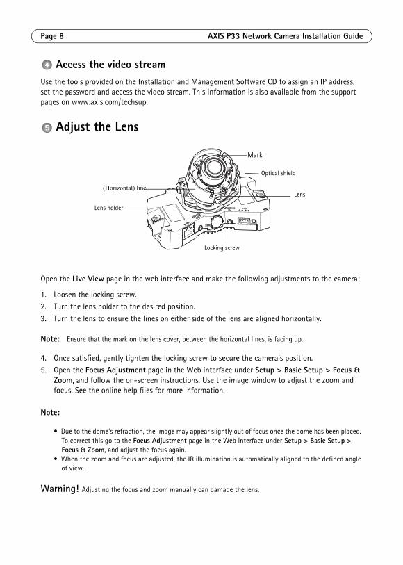
Adjust the Lens
Open the Live View page in the web interface and make the following adjustments to the camera:
1. Loosen the locking screw. 2. Turn the lens holder to the desired position.
3. Turn the lens to ensure the lines on either side of the lens are aligned horizontally.
Note: Ensure that the mark on the lens cover, between the horizontal lines, is facing up.
4. Once satisfied, gently tighten the locking screw to secure the camera’s position.
5. Open the Focus Adjustment page in the Web interface under Setup > Basic Setup > Focus & Zoom, and follow the on-screen instructions. Use the image window to adjust the zoom and focus. See the online help files for more information.
Note:
• Due to the dome’s refraction, the image may appear slightly out of focus once the dome has been placed. To correct this go to the Focus Adjustment page in the Web interface under Setup > Basic Setup > Focus & Zoom, and adjust the focus again.
• When the zoom and focus are adjusted, the IR illumination is automatically aligned to the defined angle of view.
Warning! Adjusting the focus and zoom manually can damage the lens.
Locking screw
Lens holder
Lens(Horizontal) line
Mark
Optical shield
AXIS P33 Network Camera Installation Guide Page 9
ENGLISH
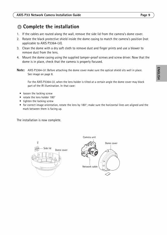
Complete the installation1. If the cables are routed along the wall, remove the side lid from the camera’s dome cover.2. Rotate the black protective shield inside the dome casing to match the camera’s position (not
applicable to AXIS P3364-LV). 3. Clean the dome with a dry soft cloth to remove dust and finger prints and use a blower to
remove dust from the lens.4. Mount the dome casing using the supplied tamper-proof screws and screw driver. Now that the
dome is in place, check that the camera is properly focused.
Note: AXIS P3364-LV: Before attaching the dome cover make sure the optical shield sits well in place. See image on page 8.
For the AXIS P3364-LV, when the lens holder is tilted at a certain angle the dome cover may block part of the IR illumination. In that case:
• loosen the locking screw• rotate the lens holder 180°• tighten the locking screw• for correct image orientation, rotate the lens by 180°; make sure the horizontal lines are aligned and the
mark between them is facing up.
The installation is now complete.
Side lidDome cover
Camera unit
Network cable
Dome cover
Page 10 AXIS P33 Network Camera Installation Guide
Unit connectorsNote: AXIS P3353 and AXIS P3354 do not support audio or I/O.
Network connector - RJ-45 Ethernet connector. Supports Power over Ethernet.
The product shall be connected using a shielded network cable (STP). All cables connecting the product to the network switch shall be shielded (STP) and intended for their specific use. Make sure that the net-work switch is properly grounded. See Electromagnetic Compatibility (EMC) on page 2 for regulatory requirements.
For AXIS P3364-LV, if not using the IR LED/heater/fan, change to PoE class 2 using the button on the back of the camera to minimize power consumption.
Audio in - 3.5mm input for a mono microphone, or a line-in mono signal (left channel is used from a stereo signal).
Audio out - Audio output (line level) that can be connected to a public address (PA) system or an active speaker with a built-in amplifier. A pair of headphones can also be attached. A stereo connector must be used for the audio out.
SDHC memory card slot - The SD memory card can be used for local recording with removable storage.
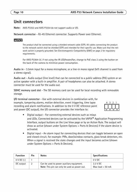
I/O terminal connector - Use with external devices in combination with, for example, tampering alarms, motion detection, event triggering, time lapse recording and alarm notifications. In addition to the 0 V DC reference point and power (DC output), the I/O connector provides the interface to:
• Digital output - For connecting external devices such as relays and LEDs. Connected devices can be activated by the VAPIX® Application Programming Interface, output buttons on the Live View page or by an Action Rule. The output will show as active (shown under System Options > Ports & Devices) if the alarm device is activated.
• Digital input - An alarm input for connecting devices that can toggle between an open and closed circuit, for example: PIRs, door/window contacts, glass break detectors, etc. When a signal is received the state changes and the input becomes active (shown under System Options > Ports & Devices).
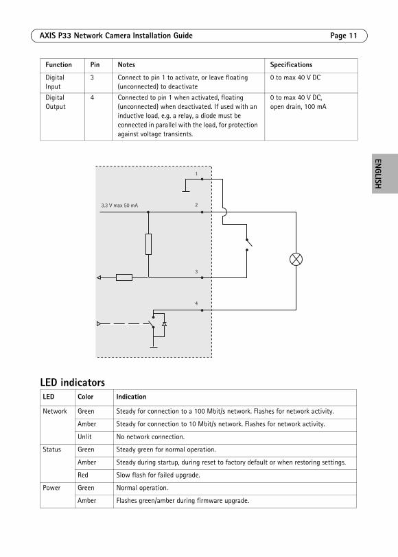
Function Pin Notes Specifications
0 V DC (-) 1 0 V DC
DC output 2 Can be used to power auxiliary equipment. Note: This pin can only be used as power out.
3.3 V DCMax load = 50 mA
4 3 2 1
AXIS P33 Network Camera Installation Guide Page 11
ENGLISH
LED indicators
Digital Input
3 Connect to pin 1 to activate, or leave floating (unconnected) to deactivate
0 to max 40 V DC
Digital Output
4 Connected to pin 1 when activated, floating (unconnected) when deactivated. If used with an inductive load, e.g. a relay, a diode must be connected in parallel with the load, for protection against voltage transients.
0 to max 40 V DC, open drain, 100 mA
LED Color Indication
Network Green Steady for connection to a 100 Mbit/s network. Flashes for network activity.
Amber Steady for connection to 10 Mbit/s network. Flashes for network activity.
Unlit No network connection.
Status Green Steady green for normal operation.
Amber Steady during startup, during reset to factory default or when restoring settings.
Red Slow flash for failed upgrade.
Power Green Normal operation.
Amber Flashes green/amber during firmware upgrade.
Function Pin Notes Specifications
3.3 V max 50 mA
1
2
3
4
Page 12 AXIS P33 Network Camera Installation Guide
Resetting to the Factory Default SettingsThis will reset all parameters, including the IP address, to the factory default settings:
1. Disconnect power from the camera.
2. Press and hold the Control button and reconnect power (see Hardware overview, on page).3. Keep the Control button pressed for about 15 seconds until the Status indicator flashes amber.
4. Release the Control button. The process is complete after about 1 minute (when the Status indicator turns green). The network camera has been reset to the factory default settings. The default IP address is 192.168.0.90
5. Re-assign the IP address.
6. Refocus the camera.
It is also possible to reset parameters to factory default via the web interface. Go to Setup > System Options > Maintenance.
Further informationThe user manual is available from the Axis Web site at www.axis.com.
To learn more about Axis' products and technologies, visit www.axis.com/academy, global learning center for network video.
Tip!Visit www.axis.com/techsup to check if there is updated firmware available for your Axis product. To see the currently installed firmware version, see Setup > About in your web interface.
WarrantyFor information about Axis' product warranty and thereto related information, please see www.axis.com/warranty
FRANÇAIS
Mesures de sécuritéLisez attentivement le présent Guide d'installation avant d'installer le produit Axis. Conservez le Guide d'installation pour une utilisation ultérieure.
• Conservez le produit Axis dans un environnement sec et aéré.
• Évitez d'exposer le produit Axis aux vibrations, aux chocs ou à une forte pression. N'installez pas le produit sur un support instable, ou des surfaces ou des murs instables ou vibrants, car cela pourrait l'endommager.
• N'utilisez que les outils applicables pour installer le produit Axis ; une force excessive pourrait endommager le produit.
• Pour le nettoyage, n’utilisez ni produits chimiques, ni substances caustiques ou aérosols. Utilisez un chiffon humide pour le nettoyage.
• N’utilisez que des accessoires conformes aux caractéristiques techniques du produit. Ceux-ci peuvent être fournis par Axis ou par un fournisseur tiers.
• Utilisez uniquement des pièces de rechange fournies ou recommandées par Axis.
• Ne tentez pas de réparer le produit vous-même, contactez Axis ou votre revendeur Axis pour toute réparation.
• Ce produit Axis doit être utilisé conformément aux lois et réglementations locales en vigueur.
• Pour pouvoir être utilisé à l'extérieur, ce produit Axis doit être placé dans un boîtier d'extérieur homologué.
• Le produit Axis doit être installé par un professionnel qualifié. Veuillez vous conformer aux règlements nationaux et locaux relatifs à l'installation.
Transport
• Pour transporter le produit Axis et éviter de l'endommager, utilisez l'emballage d'origine ou un emballage équivalent.
Remplacement des piles Ce produit Axis nécessite une pile au lithium CR2032 de 3,0 V pour l'alimentation de son horloge en temps réel interne. Dans des conditions normales d'utilisation, cette pile est censée durer au moins 5 ans. Si la pile est faible, le fonctionnement de l'horloge en temps réel peut être affecté et entraîner sa réinitialisation à chaque mise sous tension. Un message enregistré apparaît lorsque la pile doit être remplacée. Ne remplacez la pile qu'en cas de nécessité !
Si la pile doit être remplacée, veuillez contacter www.axis.com/techsup pour obtenir de l’aide.
• Jetez les piles usagées conformément aux consignes du fabricant.
• Le remplacement incorrect de la pile peut entraîner un risque d'explosion.
• Remplacez la pile par une pile identique ou équivalente uniquement, en respectant les recommandations du fabricant.
Nettoyer la bulle du dôme
• Veillez à ne pas rayer ou endommager la bulle du dôme. Ne nettoyez pas la bulle du dôme si elle semble propre à l'œil nu et ne frottez jamais sa surface. Un nettoyage excessif peut l'endommager.
• Pour le nettoyage général de la bulle du dôme, il est recommandé d'utiliser un savon ou un détergent neutre sans solvant, non abrasif, avec de l'eau et un chiffon doux. Rincez abondamment avec de l’eau tiède et propre. Séchez à l'aide d'un chiffon doux pour éviter les tâches d'eau.
• N'utilisez jamais de détergents forts, d'essence, de benzène ou d'acétone, etc. et évitez toute exposition directe aux rayons du soleil ou à des températures élevées lors du nettoyage.
• Les bulles pour les produits L sont livrées avec une surface anti-rayures et le nettoyage de la bulle est recommandé, cependant veuillez respecter les précautions ci-dessus.
Caméra réseau AXIS P33 Guide d’installation Page 15
FRANÇAIS
Guide d’installation de la Caméra réseau AXIS P33
Ce guide d’installation explique comment installer la Caméra réseau AXIS P3353/P3354/P3363-V/P3364-V/P3364-LV sur votre réseau. Pour toute autre question concernant l’utilisation du produit, reportez-vous au manuel d’utilisation, que vous trouverez sur le site www.axis.com.
Remarques :• Avant de commencer, vérifiez le contenu de l’emballage et assurez-vous que les câbles, les outils
et la documentation nécessaires sont disponibles. Voir Contenu de l’emballage ci-dessous.• Cette caméra réseau est conçue pour fonctionner avec un connecteur réseau (PoE). Si vous n’en disposez
pas, utilisez Axis PoE Midspan à 1 port (non fourni).
Contenu de l’emballage
1. “Contenu de l’emballage” à la page 15
2. “Présentation du matériel” à la page 16
3. “Montage de la caméra” à la page 174. “Accéder au flux video” à la page 18
5. “Réglage de l’objectif” à la page 18
6. “Fin de l’installation” à la page 19
Élément Modèles/variantes/remarques
Caméra réseau AXIS P3353, AXIS P3354, AXIS P3363-VAXIS P3364-V, AXIS P3364-LV
Bulles de dôme Bulle transparente non fumée (non applicable pour l’AXIS P3364-LV)Bulle transparente fumée
Étiquettes 2 étiquettes adhésives portant le numéro de série
Kit de montage Tournevis Resitorx, gabarit de perçage, connecteur de connexion
CD CD du logiciel d'installation et de gestion
Documentation imprimée Guide d’installation (le présent document)Clé d’authentification AVHS
Accessoires en option Support de fixation (spécifique à la région)Consultez le site www.axis.com pour plus d’informations sur les accessoires disponibles
Page 16 Caméra réseau AXIS P33 Guide d’installation
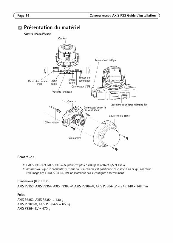
Présentation du matériel
Remarque :
• L’AXIS P3353 et l’AXIS P3354 ne prennent pas en charge les câbles E/S et audio.• Assurez-vous que le commutateur situé sous la caméra est positionné en classe 3 en ce qui concerne
l'allumage des IR (AXIS P3364-LV), ne marchant pas si configuré différemment.
Dimensions (H x L x P)AXIS P3353, AXIS P3354, AXIS P3363-V, AXIS P3364-V, AXIS P3364-LV = 97 x 148 x 148 mm
PoidsAXIS P3353, AXIS P3354 = 430 gAXIS P3363-V, AXIS P3364-V = 650 gAXIS P3364-LV = 670 g
Connecteur réseau
Voyants lumineux
Connecteur d’E/S(PoE)
Caméra
Câble réseau
Couvercle du dôme
audioEntrée
Logement pour carte mémoire SD
Vis murales
Sortie
Caméra
Connecteur de sortie du ventilateur
Microphone intégré
Bouton de
Caméra : P3363/P3364
audiocommande

Caméra réseau AXIS P33 Guide d’installation Page 17
FRANÇAIS
Montage de la caméraCe produit peut être monté avec les câbles d’alimentation acheminés à travers ou le long du mur. Ce produit peut également être doté d’un conduit métallique pour protéger le câblage lors d’un acheminement des câbles le long du mur. Référez-vous à l’illustration suivante.
Montage de la caméra directement sur le mur1. En vous servant du gabarit de perçage, percez 2 trous dans le mur.2. Acheminez et branchez le câble réseau.
3. Fixez la caméra au mur à l’aide de vis et de chevilles appropriées.
Installez la caméra au moyen d’un support de fixation (non fourni).1. En vous servant du gabarit de perçage, percez 2 trous dans le mur.
2. Acheminez tous les câbles à travers le mur et à travers les orifices du support de fixation.
3. Fixez le support de fixation au mur à l’aide de vis et de chevilles appropriées.4. Branchez le câble réseau.
5. Vous pouvez aussi brancher les câbles E/S et audio. Pour plus d’informations, reportez-vous à la page 20.
6. Si vous le souhaitez, insérez la carte mémoire SD.
7. Fixez la caméra au support de fixation à l’aide de deux vis appropriées.Remarque :
• Ces instructions concernent l’installation de la caméra sur un mur. Le support de fixation peut aussi être utilisé pour monter la caméra réseau à un boîtier de jonction.
• L’AXIS P3353 et l’AXIS P3354 ne prennent pas en charge les câbles E/S et audio.
Conduit métallique (en option, non fourni)
Support de fixation (en option, non fourni)
Câble réseau
Vis M4x8
Vis murales
Câble réseau
Page 18 Caméra réseau AXIS P33 Guide d’installation
Accéder au flux videoUtilisez le logiciel fourni sur le CD du logiciel d'installation et de gestion pour attribuer une adresse IP, définir le mot de passe et accéder au flux vidéo.
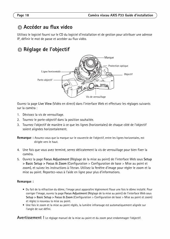
Réglage de l’objectif
Ouvrez la page Live View (Vidéo en direct) dans l’interface Web et effectuez les réglages suivants sur la caméra :
1. Dévissez la vis de verrouillage. 2. Tournez le porte-objectif dans la position souhaitée.
3. Tournez l’objectif de manière à ce que les lignes (horizontales) de chaque côté de l’objectif soient alignées horizontalement.
Remarque : Assurez-vous que la marque sur le couvercle de l’objectif, entre les lignes horizontales, est dirigée vers le haut.
4. Une fois que vous avez terminé, serrez délicatement la vis de verrouillage pour bien fixer la caméra.
5. Ouvrez la page Focus Adjustment (Réglage de la mise au point) de l’interface Web sous Setup > Basic Setup > Focus & Zoom (Configuration > Configuration de base > Mise au point et zoom), et suivez les instructions à l’écran. Utilisez la fenêtre d’image pour régler le zoom et la mise au point. Reportez-vous à l’aide en ligne pour plus d’informations.
Remarque :
• Du fait de la réfraction du dôme, l’image peut apparaître légèrement floue une fois le dôme installé. Pour corriger l’image, ouvrez la page Focus Adjustment (Réglage de la mise au point) de l’interface Web sous Setup > Basic Setup > Focus & Zoom (Configuration > Configuration de base > Mise au point et zoom) et réglez à nouveau la mise au point.
• Une fois le zoom et la mise au point réglés, la lumière infrarouge est automatiquement alignée sur l’angle de vue défini.
Avertissement ! Le réglage manuel de la mise au point et du zoom peut endommager l’objectif.
Vis de verrouillage
Porte-objectif
Objectif Ligne horizontale
Marque
Protection optique
Caméra réseau AXIS P33 Guide d’installation Page 19
FRANÇAIS
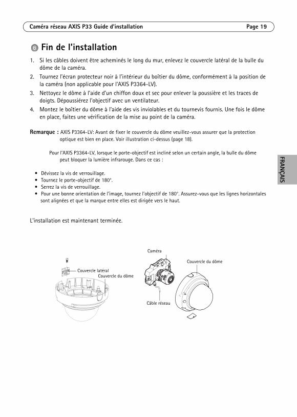
Fin de l’installation1. Si les câbles doivent être acheminés le long du mur, enlevez le couvercle latéral de la bulle du
dôme de la caméra.
2. Tournez l’écran protecteur noir à l’intérieur du boîtier du dôme, conformément à la position de la caméra (non applicable pour l’AXIS P3364-LV).
3. Nettoyez le dôme à l’aide d’un chiffon doux et sec pour enlever la poussière et les traces de doigts. Dépoussiérez l’objectif avec un ventilateur.
4. Montez le boîtier du dôme à l’aide des vis inviolables et du tournevis fournis. Une fois le dôme en place, faites une vérification de la mise au point de la caméra.
Remarque : AXIS P3364-LV: Avant de fixer le couvercle du dôme veuillez-vous assurer que la protection optique est bien en place. Voir illustration ci-dessus (page 18).
Pour l’AXIS P3364-LV, lorsque le porte-objectif est incliné selon un certain angle, la bulle du dôme peut bloquer la lumière infrarouge. Dans ce cas :
• Dévissez la vis de verrouillage.• Tournez le porte-objectif de 180°.• Serrez la vis de verrouillage.• Pour une bonne orientation de l’image, tournez l’objectif de 180°. Assurez-vous que les lignes horizontales
sont alignées et que la marque entre elles est dirigée vers le haut.
L'installation est maintenant terminée.
Couvercle latéralCouvercle du dôme
Caméra
Câble réseau
Couvercle du dôme
Page 20 Caméra réseau AXIS P33 Guide d’installation
Connecteurs de l’unitéRemarque : L’AXIS P3353 et l’AXIS P3354 ne prennent pas en charge les câbles E/S et audio.
Connecteur réseau : connecteur Ethernet RJ-45. Compatible avec l’alimentation par Ethernet.
Conformément aux réglementations locales ou environnementales et compte tenu des conditions électriques dans lesquelles le produit doit être utilisé, un câble réseau blindé (STP) peut convenir, voire s’avérer obligatoire. Les câbles réseau acheminés dans des environnements extérieurs ou similaires doivent être blindés (STP) et conçus pour cet usage spécifique. Assurez-vous que le commutateur réseau soit correctement mis à la terre. Pour consulter les réglementations correspondantes, reportez-vous à la section Compatibilité électromagnétique.
AXIS P3364-LV: En cas de non-utilisation des LEDs Infrarouge/du chauffage/du ventilateur, basculez le PoE en classe 2 en utilisant le bouton à l'arrière de la caméra pour réduire la consommation électrique.
Entrée audio : entrée de 3,5 mm pour microphone mono ou signal mono avec entrée de haut niveau (le canal de gauche est utilisé pour le signal stéréo).
Sortie audio : sortie audio (niveau de ligne) qui peut être connectée à un système d’annonce publique ou à un haut-parleur actif avec amplificateur intégré. Il est également possible de connecter une paire d’écouteurs. Un connecteur stéréo doit être utilisé pour la sortie audio.
Logement de carte mémoire SDHC : la carte mémoire SD peut être utilisée pour l’enregistrement local avec stockage amovible.
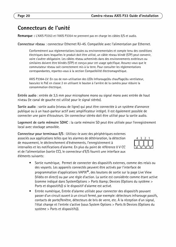
Connecteur pour terminaux E/S : Utilisez-le avec des périphériques externes associés aux applications telles que les alarmes de détérioration, la détection de mouvement, le déclenchement d'événements, l'enregistrement à intervalles et les notifications d'alarme. En plus du point de référence 0 V CC et de l'alimentation (sortie CC), le connecteur d'E/S fournit une interface aux éléments suivants:
• Sortie numérique, Permet de connecter des dispositifs externes, comme des relais ou des voyants. Les appareils connectés peuvent être activés par l'interface de programmation d'applications VAPIX®, des boutons de sortie sur la page Live View (Vidéo en direct) ou par une règle d'action. La sortie est considérée comme étant active (comme indiqué dans SystemOptions > Ports & Devices (Options du système > Ports et dispositifs)) si le dispositif d’alarme est activé.
• Entrée numérique, Entrée d'alarme utilisée pour connecter des dispositifs pouvant passer d'un circuit ouvert à un circuit fermé, par exemple: détecteurs infrarouge passifs, contacts de porte/fenêtre, détecteurs de bris de verre, etc. À la réception d'un signal, l'état change et l'entrée s'active (sous System Options > Ports & Devices (Options du système > Ports et dispositifs)).
4 3 2 1
Caméra réseau AXIS P33 Guide d’installation Page 21
FRANÇAIS
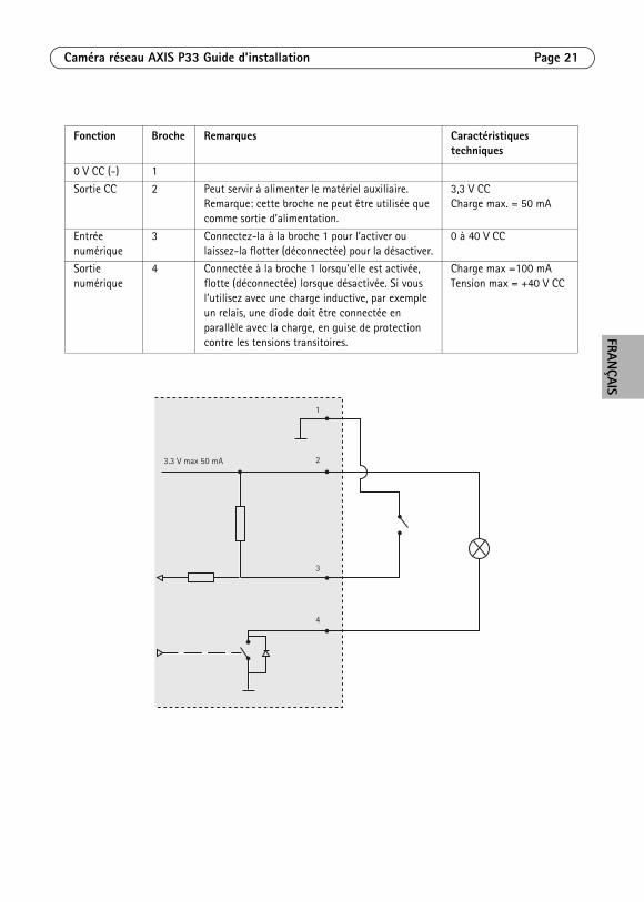
Fonction Broche Remarques Caractéristiques techniques
0 V CC (-) 1
Sortie CC 2 Peut servir à alimenter le matériel auxiliaire. Remarque: cette broche ne peut être utilisée que comme sortie d’alimentation.
3,3 V CCCharge max. = 50 mA
Entrée numérique
3 Connectez-la à la broche 1 pour l’activer ou laissez-la flotter (déconnectée) pour la désactiver.
0 à 40 V CC
Sortie numérique
4 Connectée à la broche 1 lorsqu'elle est activée, flotte (déconnectée) lorsque désactivée. Si vous l’utilisez avec une charge inductive, par exemple un relais, une diode doit être connectée en parallèle avec la charge, en guise de protection contre les tensions transitoires.
Charge max =100 mATension max = +40 V CC
3.3 V max 50 mA
1
2
3
4
Page 22 Caméra réseau AXIS P33 Guide d’installation
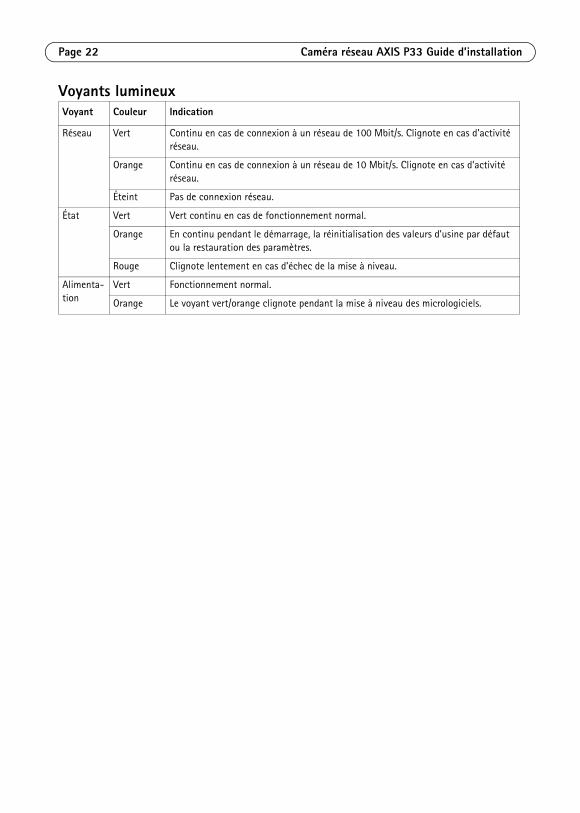
Voyants lumineuxVoyant Couleur Indication
Réseau Vert Continu en cas de connexion à un réseau de 100 Mbit/s. Clignote en cas d’activité réseau.
Orange Continu en cas de connexion à un réseau de 10 Mbit/s. Clignote en cas d’activité réseau.
Éteint Pas de connexion réseau.
État Vert Vert continu en cas de fonctionnement normal.
Orange En continu pendant le démarrage, la réinitialisation des valeurs d’usine par défaut ou la restauration des paramètres.
Rouge Clignote lentement en cas d’échec de la mise à niveau.
Alimenta-tion
Vert Fonctionnement normal.
Orange Le voyant vert/orange clignote pendant la mise à niveau des micrologiciels.
Caméra réseau AXIS P33 Guide d’installation Page 23
FRANÇAIS
Rétablissement des paramètres d’usine par défautProcédez comme suit pour rétablir les paramètres par défaut définis en usine et réinitialiser l’adresse IP :
1. Mettez la caméra hors tension.
2. Maintenez le bouton de commande enfoncé tout en remettant l’appareil sous tension (reportez-vous à la Présentation du matériel, page).
3. Appuyez sur le bouton de commande pendant environ 15 secondes jusqu’à ce que le témoin d’alimentation passe à l’orange.
4. Relâchez le bouton de commande. Le processus prend fin après environ 1 minute (lorsque le voyant d’état devient vert). Les paramètres d’usine de la caméra réseau ont été rétablis. L’adresse IP par défaut est 192.168.0.90.
5. Réattribuez l’adresse IP.
6. Recommencez la mise au point de la caméra.
Il est également possible de rétablir les paramètres d’usine à partir de l’interface web. Cliquez sur Setup > System Options > Maintenance (Configuration > Options système > Maintenance).
Plus d’informations Le manuel de l’utilisateur est disponible sur le site web d’Axis à l’adresse www.axis.com.
Pour en savoir plus sur les produits et les technologies d’Axis, rendez-vous sur www.axis.com/academy, le centre de formation mondial pour la vidéo sur IP.
Conseil utile !Consultez le site www.axis.com/techsup pour vérifier si des mises à jour des micrologiciels sont disponibles pour votre produit Axis. Pour connaître la version du micrologiciel actuellement installée, reportez-vous à la page Setup > About (Configuration > À propos de) dans votre interface web.
GarantiePour plus d'informations sur la garantie des produits Axis et des informations générales relatives à celle-ci merci de consulter le site www.axis.com/warranty

DEUTSCH
SicherheitsvorkehrungenBitte lesen Sie diese Installationsanleitung sorgfältig durch, bevor Sie mit der Installation des Axis Produkts beginnen. Halten Sie die Installationsanleitung bereit, falls Sie darauf zurückgreifen müssen.
• Lagern Sie das Axis-Produkt in einer trockenen und belüfteten Umgebung.• Setzen Sie das Axis Produkt keinen Vibrationen, Erschütterungen oder starkem Druck aus.
Installieren Sie das Produkt nicht an instabilen Halterungen oder instabilen oder vibrierenden Oberflächen oder Mauern, da dadurch das Produkt beschädigt werden könnte.
• Verwenden Sie bei der Installation des Axis Produkts nur geeignetes Werkzeug; zu hoher Kraftaufwand kann das Produkt beschädigen.
• Verwenden Sie keine chemischen, ätzenden oder aerosolhaltigen Reinigungsmittel. Verwenden Sie zur Reinigung ein feuchtes Tuch.
• Verwenden Sie nur Zubehör, das den technischen Spezifikationen des Produkts entspricht. Dieses ist von Axis oder Drittanbietern erhältlich.
• Verwenden Sie nur Ersatzteile, die von Axis empfohlen bzw. bereitgestellt wurden.• Versuchen Sie nicht, das Produkt selbst zu reparieren. Wenden Sie sich bei Service-
Angelegenheiten an Axis oder an Ihren Axis-Händler.
• Verwenden Sie dieses Axis-Produkt unter Beachtung der vor Ort geltenden rechtlichen Bestimmungen.
• Um dieses Axis-Produkt im Freien verwenden zu können, muss es in einem zugelassenen Außengehäuse installiert werden.
• Das Axis Produkt sollte nur von geschultem Fachpersonal installiert werden. Beachten Sie bei der Montage die geltenden nationalen und lokalen Bestimmungen.
Transport
• Bewahren Sie die Schutzverpackung auf. Beim Transport des Axis Produkts muss die Schutzverpackung an ihre ursprüngliche Position gesetzt werden.
Batteriewechsel Dieses Axis-Produkt ist mit einer 3,0 V CR2032 Lithium-Batterie als Stromversorgung für die interne Echtzeituhr (RTC) ausgestattet. Unter normalen Bedingungen hält die Batterie mindestens 5 Jahre. Bei entladener Batterie ist der Betrieb der Echtzeituhr nicht mehr ausreichend gewährleistet, so dass die Uhr bei jedem Systemstart zurückgesetzt wird. Sie erhalten eine Protokollnachricht, wenn ein Batteriewechsel erforderlich ist. Die Batterie sollte erst bei Bedarf gewechselt werden.
Unter www.axis.com/techsup finden Sie Informationen darüber, was Sie beim Austausch der Batterie beachten müssen.
• Verbrauchte Batterien sind gemäß den Herstelleranweisungen zu entsorgen.
• Explosionsgefahr bei fehlerhaftem Batteriewechsel!• Die Batterie muss durch dasselbe oder ein gleichwertiges Fabrikat ersetzt werden, das vom
Hersteller zugelassen ist.
Reinigung der Kuppelabdeckung
• Achten Sie darauf, die Kuppelabdeckung nicht zu zerkratzen oder zu beschädigen. Reinigen Sie die Kuppelabdeckung nicht, solange sie sauber aussieht, und polieren Sie niemals die Oberfläche. Übermäßiges Reinigen kann die Oberfläche beschädigen.
• Zur allgemeinen Reinigung einer Kuppelabdeckung wird die Verwendung einer nicht aggressiven, lösungsmittelfreien neutralen Seife bzw. eines solchen Reinigungsmittels zusammen mit Wasser und einem weichen Tuch empfohlen. Spülen Sie gut mit sauberem, lauwarmem Wasser nach. Trocknen Sie die Kuppelabdeckung mit einem weichen Tuch ab, um Wasserflecken zu vermeiden.
• Verwenden Sie niemals scharfe Reinigungsmittel, Benzin, Benzol, Aceton o. Ä., und führen Sie die Reinigung nicht unter direkter Sonneneinstrahlung oder bei hohen Temperaturen durch.
• Dome-Abdeckungen für L-Produkte sind mit einer Anti-Kratz-Oberfläche ausgestattet. Eine Reinigung des Domes wird empfohlen, allerdings sollten Sie hierbei die zuvor genannten Punkte beachten.
AXIS P33 Netzwerk-Kamera Installationsanleitung Seite 27
DEUTSCH
AXIS P33 Netzwerk-Kamera Installationsanleitung
In dieser Anleitung wird die Installation der AXIS P3353/P3354/P3363-V/P3364-V/P3364-LV Netzwerk-Kamera in einem Netzwerk beschrieben. Alle weiteren Hinweise zur Verwendung des Produkts finden Sie im Benutzerhandbuch, das auf unserer Website unter „www.axis.com“ zur Verfügung steht.
Hinweise:• Stellen Sie vor der Installation sicher, dass der Paketinhalt vollständig ist und die erforderlichen Kabel,
Werkzeugesowie die Dokumentation vorhanden sind. Siehe Inhalt des Produktpakets unten.
• Diese Netzwerk-Kamera wird über Power over Ethernet (PoE) mit Strom versorgt. Falls PoE nicht zur Verfügung steht, verwenden Sie den AXIS PoE Midspan 1-Anschluss (separat erhältlich).
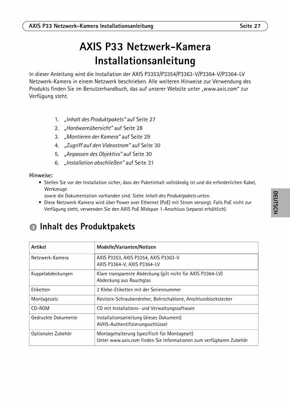
Inhalt des Produktpakets
1. „Inhalt des Produktpakets“ auf Seite 27
2. „Hardwareübersicht“ auf Seite 28
3. „Montieren der Kamera“ auf Seite 294. „Zugriff auf den Videostrom“ auf Seite 30
5. „Anpassen des Objektivs“ auf Seite 30
6. „Installation abschließen“ auf Seite 31
Artikel Modelle/Varianten/Notizen
Netzwerk-Kamera AXIS P3353, AXIS P3354, AXIS P3363-VAXIS P3364-V, AXIS P3364-LV
Kuppelabdeckungen Klare transparente Abdeckung (gilt nicht für AXIS P3364-LV)Abdeckung aus Rauchglas
Etiketten 2 Klebe-Etiketten mit der Seriennummer
Montagesatz Resitorx-Schraubendreher, Bohrschablone, Anschlussblockstecker
CD-ROM CD mit Installations- und Verwaltungssoftware
Gedruckte Dokumente Installationsanleitung (dieses Dokument)AVHS-Authentifizierungsschlüssel
Optionales Zubehör Montagehalterung (spezifisch für Montageart)Unter www.axis.com finden Sie Informationen zum verfügbaren Zubehör

Seite 28 AXIS P33 Netzwerk-Kamera Installationsanleitung
Hardwareübersicht
Hinweis:
• AXIS P3353 und AXIS P3354 unterstützen weder E/A noch Audio.• Bitte stellen Sie sicher, dass der Schalter unter der Kamera auf PoE-Klasse 3 eingestellt ist, damit die
IR-Beleuchtung (AXIS P3364-LV) aktiviert werden kann. Die Komponente funktioniert nicht, wenn eine andere Konfiguration eingestellt ist.
Abmessungen (H x B x T)AXIS P3353/AXIS P3354/AXIS P3363-V /AXIS P3364-V/AXIS P3364-LV = 97 x 148 x 148 mm
GewichtAXIS P3353/AXIS P3354 = 430 gAXIS P3363-V /AXIS P3364-V = 650 gAXIS P3364-LV = 670 g
Netzwerkanschluss
LED-Anzeigen
E/A-Anschluss(PoE)
Kameraeinheit
Netzwerkkabel
Kuppelabdeckung
AusgangAudio-
SD-Speicherkarteneinschub
Wandschrauben
Audio
Kameraeinheit
Lüfter- anschluss
Eingebautes Mikrofon
Steuertaste
Kamera: P3363/P3364
Eingang
AXIS P33 Netzwerk-Kamera Installationsanleitung Seite 29
DEUTSCH
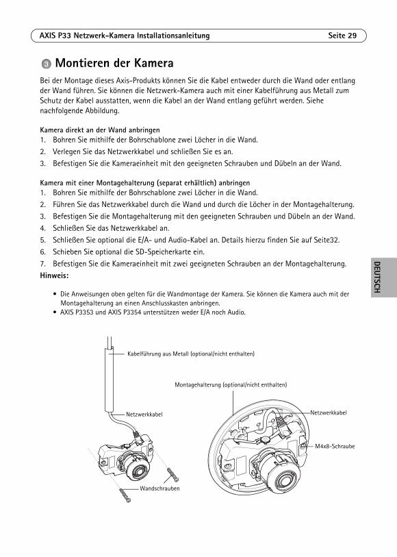
Montieren der KameraBei der Montage dieses Axis-Produkts können Sie die Kabel entweder durch die Wand oder entlang der Wand führen. Sie können die Netzwerk-Kamera auch mit einer Kabelführung aus Metall zum Schutz der Kabel ausstatten, wenn die Kabel an der Wand entlang geführt werden. Siehe nachfolgende Abbildung.
Kamera direkt an der Wand anbringen1. Bohren Sie mithilfe der Bohrschablone zwei Löcher in die Wand.
2. Verlegen Sie das Netzwerkkabel und schließen Sie es an. 3. Befestigen Sie die Kameraeinheit mit den geeigneten Schrauben und Dübeln an der Wand.
Kamera mit einer Montagehalterung (separat erhältlich) anbringen1. Bohren Sie mithilfe der Bohrschablone zwei Löcher in die Wand.2. Führen Sie das Netzwerkkabel durch die Wand und durch die Löcher in der Montagehalterung.
3. Befestigen Sie die Montagehalterung mit den geeigneten Schrauben und Dübeln an der Wand.
4. Schließen Sie das Netzwerkkabel an.5. Schließen Sie optional die E/A- und Audio-Kabel an. Details hierzu finden Sie auf Seite32.
6. Schieben Sie optional die SD-Speicherkarte ein.
7. Befestigen Sie die Kameraeinheit mit zwei geeigneten Schrauben an der Montagehalterung.Hinweis:
• Die Anweisungen oben gelten für die Wandmontage der Kamera. Sie können die Kamera auch mit der Montagehalterung an einen Anschlusskasten anbringen.
• AXIS P3353 und AXIS P3354 unterstützen weder E/A noch Audio.
Kabelführung aus Metall (optional/nicht enthalten)
Montagehalterung (optional/nicht enthalten)
Netzwerkkabel
M4x8-Schraube
Wandschrauben
Netzwerkkabel
Seite 30 AXIS P33 Netzwerk-Kamera Installationsanleitung
Zugriff auf den VideostromVerwenden Sie die auf der CD mit Installations- und Verwaltungssoftware zur Verfügung stehende Software, um eine IP-Adresse zuzuordnen, das Passwort festzulegen und auf den Videostrom zuzugreifen.
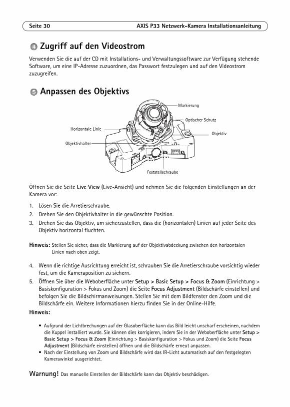
Anpassen des Objektivs
Öffnen Sie die Seite Live View (Live-Ansicht) und nehmen Sie die folgenden Einstellungen an der Kamera vor:
1. Lösen Sie die Arretierschraube.
2. Drehen Sie den Objektivhalter in die gewünschte Position.
3. Drehen Sie das Objektiv, um sicherzustellen, dass die (horizontalen) Linien auf jeder Seite des Objektiv horizontal fluchten.
Hinweis: Stellen Sie sicher, dass die Markierung auf der Objektivabdeckung zwischen den horizontalen Linien nach oben zeigt.
4. Wenn die richtige Ausrichtung erreicht ist, schrauben Sie die Arretierschraube vorsichtig wieder fest, um die Kameraposition zu sichern.
5. Öffnen Sie über die Weboberfläche unter Setup > Basic Setup > Focus & Zoom (Einrichtung > Basiskonfiguration > Fokus und Zoom) die Seite Focus Adjustment (Bildschärfe einstellen) und befolgen Sie die Bildschirmanweisungen. Stellen Sie mit dem Bildfenster den Zoom und die Bildschärfe ein. Weitere Informationen hierzu finden Sie in der Online-Hilfe.
Hinweis:
• Aufgrund der Lichtbrechungen auf der Glasoberfläche kann das Bild leicht unscharf erscheinen, nachdem die Kuppel installiert wurde. Sie können dies korrigieren, indem Sie in der Weboberfläche unter Setup > Basic Setup > Focus & Zoom (Einrichtung > Basiskonfiguration > Fokus und Zoom) die Seite Focus Adjustment (Bildschärfe einstellen) öffnen und die Bildschärfe erneut anpassen.
• Nach der Einstellung von Zoom und Bildschärfe wird das IR-Licht automatisch auf den festgelegten Kamerawinkel ausgerichtet.
Warnung! Das manuelle Einstellen der Bildschärfe kann das Objektiv beschädigen.
Feststellschraube
Objektivhalter
ObjektivHorizontale Linie
Markierung
Optischer Schutz
AXIS P33 Netzwerk-Kamera Installationsanleitung Seite 31
DEUTSCH
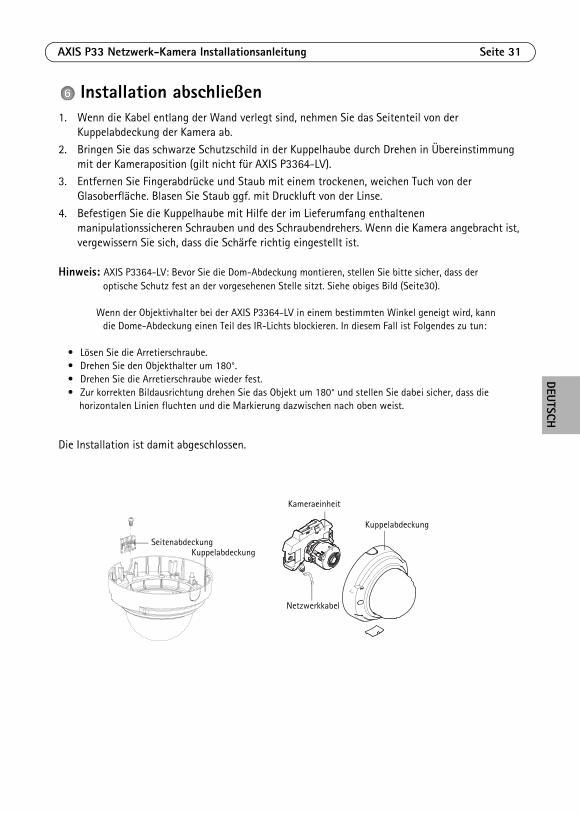
Installation abschließen1. Wenn die Kabel entlang der Wand verlegt sind, nehmen Sie das Seitenteil von der
Kuppelabdeckung der Kamera ab.
2. Bringen Sie das schwarze Schutzschild in der Kuppelhaube durch Drehen in Übereinstimmung mit der Kameraposition (gilt nicht für AXIS P3364-LV).
3. Entfernen Sie Fingerabdrücke und Staub mit einem trockenen, weichen Tuch von der Glasoberfläche. Blasen Sie Staub ggf. mit Druckluft von der Linse.
4. Befestigen Sie die Kuppelhaube mit Hilfe der im Lieferumfang enthaltenen manipulationssicheren Schrauben und des Schraubendrehers. Wenn die Kamera angebracht ist, vergewissern Sie sich, dass die Schärfe richtig eingestellt ist.
Hinweis: AXIS P3364-LV: Bevor Sie die Dom-Abdeckung montieren, stellen Sie bitte sicher, dass der optische Schutz fest an der vorgesehenen Stelle sitzt. Siehe obiges Bild (Seite30).
Wenn der Objektivhalter bei der AXIS P3364-LV in einem bestimmten Winkel geneigt wird, kann die Dome-Abdeckung einen Teil des IR-Lichts blockieren. In diesem Fall ist Folgendes zu tun:
• Lösen Sie die Arretierschraube.• Drehen Sie den Objekthalter um 180°.• Drehen Sie die Arretierschraube wieder fest.• Zur korrekten Bildausrichtung drehen Sie das Objekt um 180° und stellen Sie dabei sicher, dass die
horizontalen Linien fluchten und die Markierung dazwischen nach oben weist.
Die Installation ist damit abgeschlossen.
SeitenabdeckungKuppelabdeckung
Kameraeinheit
Netzwerkkabel
Kuppelabdeckung
Seite 32 AXIS P33 Netzwerk-Kamera Installationsanleitung
GeräteanschlüsseHinweis: AXIS P3353 und AXIS P3354 unterstützen weder E/A noch Audio.
Netzwerkanschluss – RJ-45-Ethernetanschluss. Unterstützt Power over Ethernet.
Aufgrund örtlicher Bestimmungen oder Umgebungs- und elektrischen Bedingungen, in denen das Produkt eingesetzt werden soll, ist eventuell ein abgeschirmtes Netzwerkkabel (STP) vorteilhaft oder erforderlich. Netzwerkkabel, welche in Außenumgebungen oder ähnlichem geführt werden, müssen abgeschirmt sein (STP) und für diesen Zweck vorgesehen sein. Stellen Sie sicher, dass der Netzwerk-Switch ordnungsgemäß geerdet ist. Behördliche Anforderungen finden Sie unter „Elektromagnetische Verträglichkeit (EMV)“.
AXIS P3364-V: Wenn Sie die IR LED/Heizung/Lüfter nicht verwenden, dann stellen Sie bitte auf der Rückseite der Kamera die PoE-Klasse 2 ein, um den Stromverbrauch zu minimieren.
Audioeingang – 3,5-mm-Anschluss für ein Monomikrofon oder ein Monosignal (linker Kanal wird von einem Stereosignal benutzt).
Audioausgang – Audioausgang (Leistungsstufe) zum Anschließen einer Rundrufanlage (PA) oder eines Aktivlautsprechers mit integriertem Verstärker. Auch ein Kopfhörer kann angeschlossen werden. Für den Audioausgang muss ein Stereostecker benutzt werden.
SDHC-Speicherkarteneinschub – Die SD-Speicherkarte kann zur lokalen Aufzeichnung mit Wechselmedien verwendet werden.
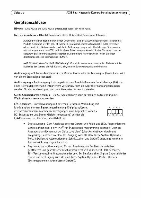
E/A-Anschluss - Zur Verwendung mit externen Geräten in Verbindung mit Manipulationsalarmen, Bewegungserkennung, Ereignisauslösung, Zeitrafferaufnahmen, Alarmbenachrichtigungen usw. Abgesehen vom 0 V DC-Bezugspunkt und Strom (Gleichstromausgang) verfügt die E/A-Klemmenleiste über eine Schnittstelle zu:
• Digitalausgang– Zum Anschluss externer Geräte, wie Relais und LEDs. Angeschlossene Geräte können über die VAPIX® API (Application Programming Interface), über die Ausgabeschaltflächen auf der Seite „Live View“ (Live-Ansicht) oder durch eine Ereignisregel aktiviert werden. Der Ausgang wird als aktiv (siehe System Options > Ports & Devices (Systemoptionen > Schnittstellen und Geräte)) angezeigt, wenn die Alarmvorrichtung eingeschaltet ist.
• Digitaleingang – Alarmeingang für den Anschluss von Geräten, die zwischen geöffnetem und geschlossenem Schaltkreis wechseln können, z B.: PIR-Sensoren, Tür-/Fensterkontakte, Glasbruchmelder usw. Bei Empfang eines Signals ändert sich der Status und der Eingang wird aktiviert (siehe System Options > Ports & Devices (Systemoptionen > Anschlüsse & Geräte)).
4 3 2 1
AXIS P33 Netzwerk-Kamera Installationsanleitung Seite 33
DEUTSCH
.
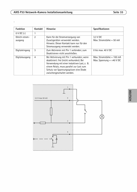
Funktion Kontakt Hinweise Spezifikationen
0 V DC (-) 1
Gleich-strom-ausgang
2 Kann für die Stromversorgung von Zusatzgeräten verwendet werden. Hinweis: Dieser Kontakt kann nur für den Stromausgang verwendet werden.
3,3 V DCMax. Stromstärke = 50 mA
Digitaleingang 3 Zum Aktivieren mit Pin 1 verbinden; zum Deaktivieren nicht anschließen.
0 bis max. 40 V DC
Digitalausgang 4 Bei Aktivierung mit Pin 1 verbunden; wenn deaktiviert: frei (nicht verbunden). Bei Verwendung mit einer induktiven Last, z. B. einem Relais, muss parallel zur Last zum Schutz vor Spannungsspitzen eine Diode zwischengeschaltet werden.
Max. Stromstärke = 100 mAMax. Spannung = +40 V DC
3.3 V max 50 mA
1
2
3
4
Seite 34 AXIS P33 Netzwerk-Kamera Installationsanleitung
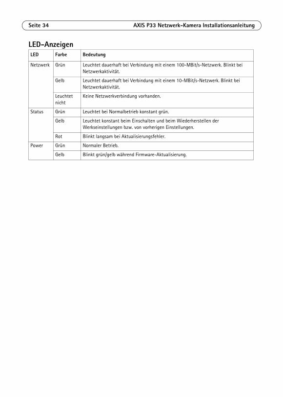
LED-AnzeigenLED Farbe Bedeutung
Netzwerk Grün Leuchtet dauerhaft bei Verbindung mit einem 100-MBit/s-Netzwerk. Blinkt bei Netzwerkaktivität.
Gelb Leuchtet dauerhaft bei Verbindung mit einem 10-MBit/s-Netzwerk. Blinkt bei Netzwerkaktivität.
Leuchtet nicht
Keine Netzwerkverbindung vorhanden.
Status Grün Leuchtet bei Normalbetrieb konstant grün.
Gelb Leuchtet konstant beim Einschalten und beim Wiederherstellen der Werkseinstellungen bzw. von vorherigen Einstellungen.
Rot Blinkt langsam bei Aktualisierungsfehler.
Power Grün Normaler Betrieb.
Gelb Blinkt grün/gelb während Firmware-Aktualisierung.
AXIS P33 Netzwerk-Kamera Installationsanleitung Seite 35
DEUTSCH
Wiederherstellen der werkseitigen StandardeinstellungenGehen Sie wie folgt vor, um sämtliche Parameter einschließlich der IP-Adresse auf die werkseitigen Standardeinstellungen zurückzusetzen:
1. Trennen Sie die Kamera von der Stromversorgung.
2. Halten Sie die Steuertaste gedrückt, und stellen Sie die Stromversorgung wieder her (siehe „Hardwareübersicht“ auf Seite ).
3. Halten Sie die Steuertaste etwa 15 Sekunden gedrückt, bis die Statusanzeige gelb blinkt.
4. Lassen Sie die Steuertaste los. Der Vorgang ist nach etwa 1 Minute abgeschlossen (die Statusanzeige wird grün). Die Netzwerk-Kamera wurde auf die werkseitigen Standardeinstellungen zurückgesetzt. Die Standard-IP-Adresse lautet 192.168.0.90.
5. Weisen Sie die IP-Adresse erneut zu.
6. Führen Sie die Fokussierung der Kamera erneut durch.Die Parameter können auch über die Weboberfläche auf die werkseitigen Einstellungen zurückgesetzt werden. Wählen Sie „Setup > System Options > Maintenance“ (Setup > Systemoptionen > Wartung).
Weitere InformationenDas Benutzerhandbuch steht auf der Website von Axis unter „www.axis.com“ zur Verfügung.
Um mehr über Produkte und Technologien von Axis zu erfahren, besuchen Sie uns unter „www.axis.com/academy“, dem globalem Lernzentrum für Netzwerk-Video.
Tipp!Unter „www.axis.com/techsup“ finden Sie Firmware-Aktualisierungen für Ihr Axis-Produkt. Informationen zur aktuellen Firmware-Version finden Sie in Ihrer Weboberfläche unter „Setup“ > „About“ (Info).
GarantieDie Garantiebedingungen für Axis Produkte sowie weitere Informationen zum Thema Garantie finden Sie unter www.axis.com/warranty

ITALIANO
SicurezzaLeggere attentamente questa Guida all'installazione prima di installare un prodotto Axis. Conservare la Guida all'installazione per ulteriori riferimenti.
• Conservare il prodotto Axis in un ambiente asciutto e ben ventilato.
• Evitare di esporre il prodotto Axis alle vibrazioni, agli urti o a forte pressione. Non installare il prodotto su staffe instabili, superfici o pareti instabili o vibranti, poiché ciò potrebbe danneggiare il prodotto.
• Utilizzare solo strumenti idonei quando si installa il prodotto Axis. Una forza eccessiva potrebbe danneggiare il prodotto.
• Non utilizzare sostanze chimiche, agenti caustici o detergenti spray. Utilizzare un panno umido per la pulizia.
• Utilizzare solo accessori conformi con le specifiche tecniche del prodotto. Queste possono essere fornite da Axis o da terze parti.
• Utilizzare solo parti di ricambio fornite o raccomandate da Axis.
• Non tentare di riparare il prodotto da soli, contattare Axis o il rivenditore di zona Axis per assistenza.
• Questo prodotto Axis deve essere utilizzato in conformità alle leggi e alle disposizioni locali.• Per utilizzare questo prodotto Axis all'esterno, è necessario installarlo in un alloggiamento
per esterni approvato.• Il prodotto Axis deve essere installato da un tecnico qualificato. Osservare le disposizioni
nazionali e locali per l'installazione.
Trasporto
• Quando si trasporta il prodotto Axis, utilizzare l'imballo originale o un imballo equivalente per evitare di danneggiare il prodotto.
Sostituzione della batteriaQuesto prodotto Axis utilizza una batteria al litio CR2032 da 3.0 V per alimentare il real-time clock (RTC) interno. In normali condizioni questa batteria ha una durata di almeno 5 anni. La batteria scarica influisce sul funzionamento dell'RTC, che viene reimpostato ad ogni accensione. Un messaggio di registro apparirà quando la batteria dovrà essere sostituita. La batteria non deve essere sostituita a meno che non sia necessario.
Se la batteria non deve essere sostituita, contattare www.axis.com/techsup per assistenza.
• Smaltire le batterie usate secondo le istruzioni del produttore.
• Rischio di esplosione se la batteria non viene sostituita correttamente.
• Sostituire solo con una batteria identica o equivalente, come raccomandato dal produttore.
Pulizia della copertura a cupola
• Fare attenzione a non graffiare o danneggiare la copertura a cupola. Non pulire una copertura a cupola visivamente pulita e non lucidare mai la superficie. Una pulizia eccessiva potrebbe danneggiare la superficie.
• Per la pulizia generale della copertura a cupola si raccomanda l'uso di un sapone neutro, non abrasivo e privo di solventi o di un detergente con acqua e un panno morbido. Risciacquare perfettamente con acqua tiepida pulita. Asciugare con un panno morbido per evitare macchie d'acqua.
• Non utilizzare detergenti irritanti, benzina, benzene o acetone, ecc. ed evitare di pulire alla luce diretta del sole o a temperature elevate.
• Le cupole per i prodotti in versione L sono caratterizzate da superfici antigraffio e ne è possibile e consigliata la pulitura. Tuttavia si prega di osservare le seguenti precauzioni.
AXIS P33 Network Camera Guida all'installazione Pagina 39
ITALIANO
Guida all'installazione diAXIS P33 Network Camera
Questo documento fornisce le istruzioni necessarie per installare una AXIS P3353/P3354/P3363-V/P3364-V/P3364-LV Network Camera nella rete in uso. Per tutte le altre informazioni relative all'uso del prodotto, consultare la Guida per l'utente, disponibile sul sito www.axis.com
Note:• Prima di iniziare, verificare che la confezione contenga i cavi, gli attrezzi
e la documentazione necessari. Vedere Contenuto della confezione di seguito.• Questa telecamera di rete è progettata per essere utilizzata con la tecnologia PoE. Se non disponibile,
utilizzare un midspan PoE AXIS a 1 porta (non fornito di serie).
Contenuto della confezione
1. “Contenuto della confezione” alla pagina 39
2. “Panoramica dell’hardware” alla pagina 40
3. “Montaggio della telecamera” alla pagina 414. “Accesso al flusso video” alla pagina 42
5. “Regolazione dell'obiettivo” alla pagina 42
6. “Completamento dell'installazione” alla pagina 43
Elemento Modelli/varianti/note
Telecamera di rete AXIS P3353, AXIS P3354, AXIS P3363-VAXIS P3364-V, AXIS P3364-LV
Coperture a cupola Copertura trasparente chiara (non applicabile a AXIS P3364-LV)Copertura trasparente sfumata
Etichette 2 etichette adesive con numero di serie
Kit di montaggio Cacciavite Resitorx, maschera di foratura, morsettiera
CD CD di installazione e gestione
Materiali stampati Guida all'installazione (questo documento)Chiave di autenticazione AVHS
Accessori opzionali Staffa di montaggio (specifica per Paese)Visitare il sito web www.axis.com per informazioni sugli accessori disponibili
Pagina 40 AXIS P33 Network Camera Guida all'installazione
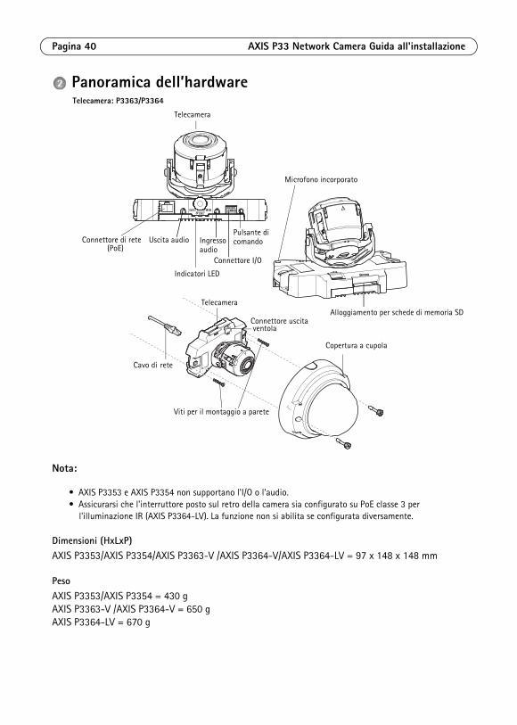
Panoramica dell’hardware
Nota:
• AXIS P3353 e AXIS P3354 non supportano l'I/O o l'audio.• Assicurarsi che l'interruttore posto sul retro della camera sia configurato su PoE classe 3 per
l'illuminazione IR (AXIS P3364-LV). La funzione non si abilita se configurata diversamente.
Dimensioni (HxLxP)AXIS P3353/AXIS P3354/AXIS P3363-V /AXIS P3364-V/AXIS P3364-LV = 97 x 148 x 148 mm
PesoAXIS P3353/AXIS P3354 = 430 g AXIS P3363-V /AXIS P3364-V = 650 g AXIS P3364-LV = 670 g
Indicatori LED
Connettore I/O
Telecamera
Cavo di rete
Copertura a cupola
Uscita audio Ingresso
Alloggiamento per schede di memoria SD
Viti per il montaggio a parete
Telecamera
Connettore uscita ventola
Microfono incorporato
Pulsante di
Telecamera: P3363/P3364
Connettore di rete(PoE) audio
comando
AXIS P33 Network Camera Guida all'installazione Pagina 41
ITALIANO
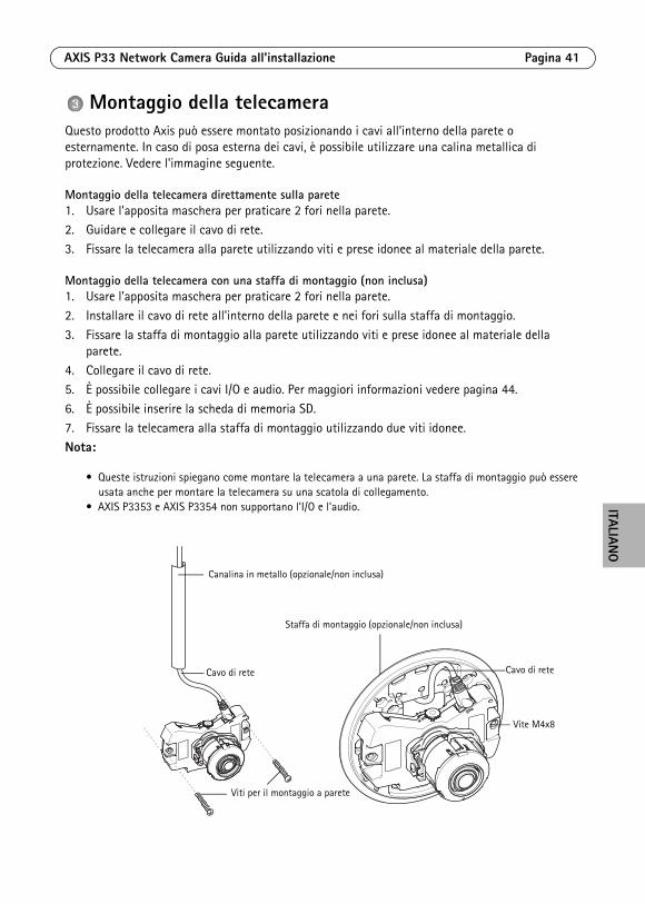
Montaggio della telecameraQuesto prodotto Axis può essere montato posizionando i cavi all’interno della parete o esternamente. In caso di posa esterna dei cavi, è possibile utilizzare una calina metallica di protezione. Vedere l'immagine seguente.
Montaggio della telecamera direttamente sulla parete1. Usare l'apposita maschera per praticare 2 fori nella parete.2. Guidare e collegare il cavo di rete.
3. Fissare la telecamera alla parete utilizzando viti e prese idonee al materiale della parete.
Montaggio della telecamera con una staffa di montaggio (non inclusa)1. Usare l'apposita maschera per praticare 2 fori nella parete.
2. Installare il cavo di rete all'interno della parete e nei fori sulla staffa di montaggio.
3. Fissare la staffa di montaggio alla parete utilizzando viti e prese idonee al materiale della parete.
4. Collegare il cavo di rete.5. È possibile collegare i cavi I/O e audio. Per maggiori informazioni vedere pagina 44.
6. È possibile inserire la scheda di memoria SD.
7. Fissare la telecamera alla staffa di montaggio utilizzando due viti idonee.Nota:
• Queste istruzioni spiegano come montare la telecamera a una parete. La staffa di montaggio può essere usata anche per montare la telecamera su una scatola di collegamento.
• AXIS P3353 e AXIS P3354 non supportano l'I/O e l'audio.
Canalina in metallo (opzionale/non inclusa)
Staffa di montaggio (opzionale/non inclusa)
Cavo di rete
Vite M4x8
Viti per il montaggio a parete
Cavo di rete
Pagina 42 AXIS P33 Network Camera Guida all'installazione
Accesso al flusso videoUtilizzare gli strumenti software forniti nel CD d’Installazione e Gestione per assegnare indirizzi IP, impostare password e accedere al flusso video. È anche possibile consultare la pagina www.axis.com/techsup per reperire gli stessi.
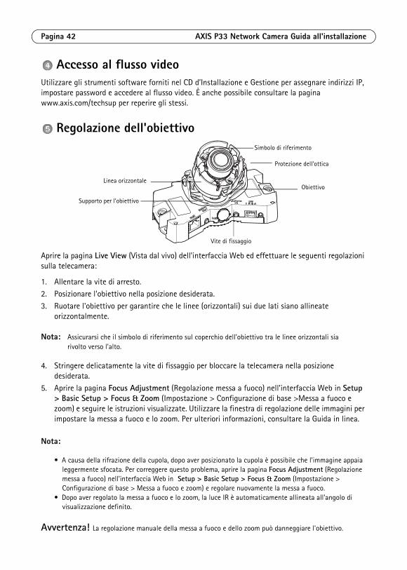
Regolazione dell'obiettivo
Aprire la pagina Live View (Vista dal vivo) dell'interfaccia Web ed effettuare le seguenti regolazioni sulla telecamera:
1. Allentare la vite di arresto. 2. Posizionare l'obiettivo nella posizione desiderata.
3. Ruotare l'obiettivo per garantire che le linee (orizzontali) sui due lati siano allineate orizzontalmente.
Nota: Assicurarsi che il simbolo di riferimento sul coperchio dell'obiettivo tra le linee orizzontali sia rivolto verso l'alto.
4. Stringere delicatamente la vite di fissaggio per bloccare la telecamera nella posizione desiderata.
5. Aprire la pagina Focus Adjustment (Regolazione messa a fuoco) nell'interfaccia Web in Setup > Basic Setup > Focus & Zoom (Impostazione > Configurazione di base >Messa a fuoco e zoom) e seguire le istruzioni visualizzate. Utilizzare la finestra di regolazione delle immagini per impostare la messa a fuoco e lo zoom. Per ulteriori informazioni, consultare la Guida in linea.
Nota:
• A causa della rifrazione della cupola, dopo aver posizionato la cupola è possibile che l'immagine appaia leggermente sfocata. Per correggere questo problema, aprire la pagina Focus Adjustment (Regolazione messa a fuoco) nell'interfaccia Web in Setup > Basic Setup > Focus & Zoom (Impostazione > Configurazione di base > Messa a fuoco e zoom) e regolare nuovamente la messa a fuoco.
• Dopo aver regolato la messa a fuoco e lo zoom, la luce IR è automaticamente allineata all'angolo di visualizzazione definito.
Avvertenza! La regolazione manuale della messa a fuoco e dello zoom può danneggiare l'obiettivo.
Vite di fissaggio
Supporto per l'obiettivo
ObiettivoLinea orizzontale
Simbolo di riferimento
Protezione dell’ottica
AXIS P33 Network Camera Guida all'installazione Pagina 43
ITALIANO
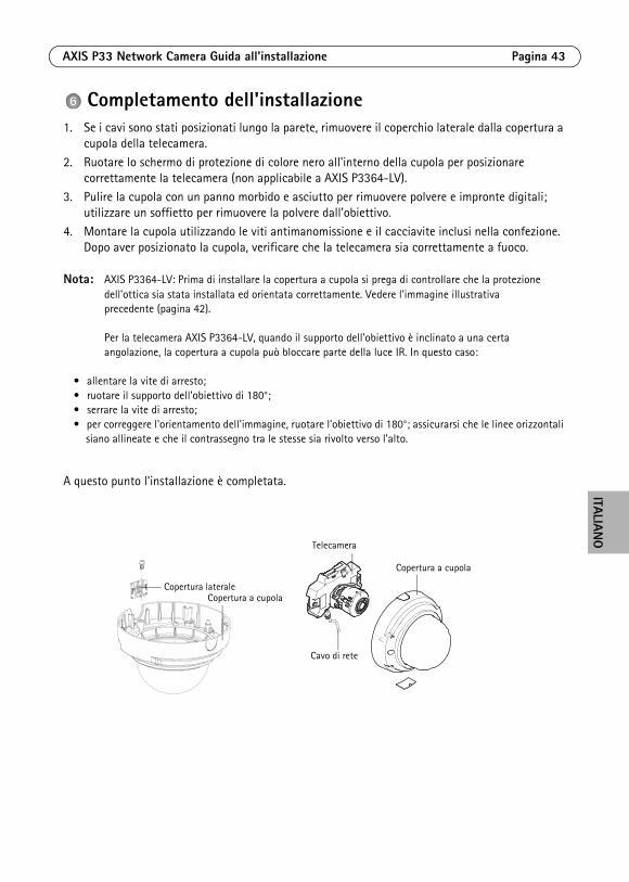
Completamento dell'installazione1. Se i cavi sono stati posizionati lungo la parete, rimuovere il coperchio laterale dalla copertura a
cupola della telecamera.
2. Ruotare lo schermo di protezione di colore nero all'interno della cupola per posizionare correttamente la telecamera (non applicabile a AXIS P3364-LV).
3. Pulire la cupola con un panno morbido e asciutto per rimuovere polvere e impronte digitali; utilizzare un soffietto per rimuovere la polvere dall'obiettivo.
4. Montare la cupola utilizzando le viti antimanomissione e il cacciavite inclusi nella confezione. Dopo aver posizionato la cupola, verificare che la telecamera sia correttamente a fuoco.
Nota: AXIS P3364-LV: Prima di installare la copertura a cupola si prega di controllare che la protezione dell'ottica sia stata installata ed orientata correttamente. Vedere l'immagine illustrativa precedente (pagina 42).
Per la telecamera AXIS P3364-LV, quando il supporto dell'obiettivo è inclinato a una certa angolazione, la copertura a cupola può bloccare parte della luce IR. In questo caso:
• allentare la vite di arresto;• ruotare il supporto dell'obiettivo di 180°;• serrare la vite di arresto;• per correggere l'orientamento dell'immagine, ruotare l'obiettivo di 180°; assicurarsi che le linee orizzontali
siano allineate e che il contrassegno tra le stesse sia rivolto verso l'alto.
A questo punto l'installazione è completata.
Copertura lateraleCopertura a cupola
Telecamera
Cavo di rete
Copertura a cupola
Pagina 44 AXIS P33 Network Camera Guida all'installazione
ConnettoriNota: AXIS P3353 e AXIS P3354 non supportano l'I/O o l'audio.
Connettore di rete. Connettore RJ-45 Ethernet. Supporta Power over Ethernet.
A causa delle disposizioni locali e delle condizioni ambientali ed elettriche in cui il prodotto deve essere usato, può essere appropriato o necessario un cavo di rete schermato (STP). I cavi di rete usati in ambienti esterni o simili devono essere schermati (STP) e destinati al loro uso specifico. Assicurarsi che lo switch di rete sia adeguatamente connesso a terra. Per i requisiti di legge vedere le norme di Compatibilità elettromagnetica (EMC).
AXIS P3364-LV: Se non si utilizzano la lampada IR/riscaldatore/ventilatore, cambiare l'alimentazione a PoE classe 2 tramite il bottone posto sul retro della telecamera per minimizzare il consumo di corrente.
Ingresso audio. Ingresso audio da 3,5 mm per microfono in mono o segnale mono line-in (il canale sinistro è usato da un segnale stereo).
Uscita audio. Uscita audio che può essere connessa a un sistema di indirizzo pubblico (PA) oppure a un altoparlante con amplificatore integrato. È possibile collegare un paio di cuffie. Per l'uscita audio è necessario usare un connettore stereo.
Slot per scheda di memoria SDHC. Le schede di memoria SD possono essere usate per la registrazione locale con unità di memorizzazione rimovibili.
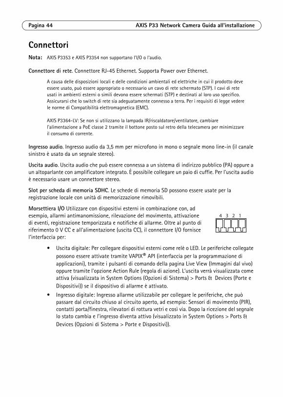
Morsettiera I/O Utilizzare con dispositivi esterni in combinazione con, ad esempio, allarmi antimanomissione, rilevazione del movimento, attivazione di eventi, registrazione temporizzata e notifiche di allarme. Oltre al punto di riferimento 0 V CC e all'alimentazione (uscita CC), il connettore I/O fornisce l'interfaccia per:
• Uscita digitale: Per collegare dispositivi esterni come relè o LED. Le periferiche collegate possono essere attivate tramite VAPIX® API (interfaccia per la programmazione di applicazioni), tramite i pulsanti di comando della pagina Live View (Immagini dal vivo) oppure tramite l'opzione Action Rule (regola di azione). L’uscita verrà visualizzata come attiva (visualizzata in System Options (Opzioni di Sistema) > Ports & Devices (Porte e Dispositivi)) se il dispositivo di allarme è attivato.
• Ingresso digitale: Ingresso allarme utilizzabile per collegare le periferiche, che può passare dal circuito chiuso al circuito aperto, ad esempio: Sensori di movimento (PIR), contatti porta/finestra, rilevatori di rottura vetri e così via. Dopo la ricezione del segnale lo stato cambia e l’ingresso diventa attivo (visualizzato in System Options > Ports & Devices (Opzioni di Sistema > Porte e Dispositivi)).
4 3 2 1
AXIS P33 Network Camera Guida all'installazione Pagina 45
ITALIANO
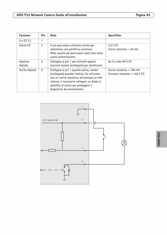
Funzione Pin Note Specifiche
0 V CC (-) 1
Uscita CC 2 Il pin può essere utilizzato anche per alimentare una periferica ausiliaria.Nota: questo pin può essere usato solo come uscita alimentazione.
3,3 V CCCarico massimo = 50 mA
Ingresso digitale
3 Collegare al pin 1 per attivarlo oppure lasciarlo isolato (scollegato) per disattivarlo
da 0 a max 40 V CC
Uscita digitale 4 Collegare al pin 1 quando attiva, isolata (scollegata) quando inattiva. Se utilizzata con un carico induttivo, ad esempio un relè esterno, è necessario collegare un diodo in parallelo al carico per proteggere il dispositivo da sovratensioni.
Carico massimo = 100 mATensione massima = +40 V CC
3.3 V max 50 mA
1
2
3
4
Pagina 46 AXIS P33 Network Camera Guida all'installazione
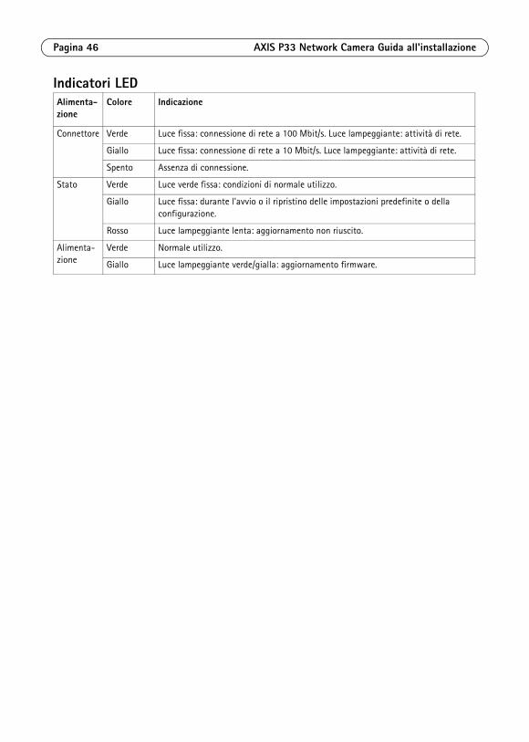
Indicatori LEDAlimenta-zione
Colore Indicazione
Connettore Verde Luce fissa: connessione di rete a 100 Mbit/s. Luce lampeggiante: attività di rete.
Giallo Luce fissa: connessione di rete a 10 Mbit/s. Luce lampeggiante: attività di rete.
Spento Assenza di connessione.
Stato Verde Luce verde fissa: condizioni di normale utilizzo.
Giallo Luce fissa: durante l'avvio o il ripristino delle impostazioni predefinite o della configurazione.
Rosso Luce lampeggiante lenta: aggiornamento non riuscito.
Alimenta-zione
Verde Normale utilizzo.
Giallo Luce lampeggiante verde/gialla: aggiornamento firmware.
AXIS P33 Network Camera Guida all'installazione Pagina 47
ITALIANO
Ripristino delle impostazioni predefiniteQuesta procedura consentirà di ripristinare le impostazioni predefinite per tutti i parametri, incluso l'indirizzo IP.
1. Scollegare l'alimentazione dalla telecamera.
2. Tenere premuto il pulsante Control e ricollegare il cavo di alimentazione (vedere Panoramica dell'hardware a pagina ).
3. Tenere premuto il pulsante di comando per circa 15 secondi, fino a quando l'indicatore di stato non lampeggia in giallo.
4. Rilasciare il pulsante di comando. Il processo è completo dopo circa 1 minuto (quando l'indicatore di stato diventa verde). La telecamera di rete è stata reimpostata alle impostazioni predefinite in fabbrica. L'indirizzo IP predefinito è 192.168.0.90
5. Riassegnare l'indirizzo IP.
6. Rimettere a fuoco la telecamera.
È inoltre possibile reimpostare i parametri alle impostazioni predefinite di fabbrica mediante l'interfaccia Web. Selezionare Setup > System Options > Maintenance (Impostazioni > Opzioni di sistema > Manutenzione)
Ulteriori informazioniLa Guida per l'utente è disponibile sul sito Web di Axis all'indirizzo www.axis.com
Per maggiori informazioni sui prodotti e sulle tecnologie Axis visitare il sito www.axis.com/academy, centro di apprendimento globale per i video di rete.
Suggerimento!Visitare il sito di Axis all'indirizzo www.axis.com/techsup per verificare la disponibilità di aggiornamenti del firmware per il proprio prodotto Axis. Per conoscere la versione installata del software, selezionare Setup > About (Configurazione > Informazioni su) nell'interfaccia Web.
GaranziaPer informazioni relative alla garanzia del prodotto AXIS ed ogni altra ulteriore informazione correlata, si prega di consultare la pagina http://www.axis.com/warranty

ESPAÑO
L
Medidas preventivasLea detenidamente esta Guía de instalación antes de instalar el producto Axis. Guarde la Guía de instalación para poder consultarla en el futuro.
• Guarde el producto Axis en un entorno seco y ventilado.
• Evite exponer el producto Axis a vibraciones, golpes o presiones excesivas. No instale el producto en soportes inestables ni en superficies o paredes inestables o con vibraciones, ya que esto podría dañarlo.
• Utilice solo las herramientas apropiadas para instalar el producto Axis; una fuerza excesiva podría dañarlo.
• No utilice productos químicos, agentes cáusticos ni limpiadores en aerosol. Límpielo con un paño húmedo.
• Utilice solo accesorios que cumplan las especificaciones técnicas del producto. Puede obtenerlos de Axis o de un tercero.
• Utilice solo piezas de recambio suministradas o recomendadas por Axis.
• No intente reparar el producto usted mismo, póngase en contacto con Axis o con el distribuidor de Axis para los temas de servicio técnico.
• Este producto Axis se utilizará de conformidad con la legislación y normativas locales.• Para utilizar este producto Axis en exteriores, se instalará en una carcasa protectora para
exteriores aprobada.• La instalación del producto Axis debe realizarla un profesional cualificado. Siga las
normativas nacionales y locales aplicables para la instalación.
Transporte
• A la hora de transportar el producto Axis, utilice el embalaje original o uno equivalente para no dañar el producto.
Sustitución de la batería Este producto Axis utiliza una batería de litio CR2032 3.0 de 3,0 V como fuente de alimentación para su reloj de tiempo real interno (RTC). En condiciones normales, esta batería durará un mínimo de 5 años. Cuando la batería tiene poca carga, el funcionamiento del RTC se puede ver afectado, ya que esto puede hacer que se reinicie cada vez que se encienda. Aparecerá un mensaje de registro cuando sea necesario sustituir la batería. No se debe sustituir la batería a menos que sea necesario.
Si necesita sustituir la batería, visite la página www.axis.com/techsup para recibir asistencia.
• Deseche las baterías usadas según las instrucciones del fabricante.
• Existe peligro de explosión si la batería se sustituye de forma incorrecta.
• Utilice solo baterías de recambio iguales o equivalentes, de acuerdo con las recomendaciones del fabricante.
Limpieza de la cubierta del domo
• Tenga cuidado de no arañar ni dañar la cubierta del domo. No limpie una cubierta del domo que parezca limpia y no pula nunca la superficie. El exceso de limpieza podría dañar la superficie.
• Para la limpieza general de la cubierta del domo se recomienda utilizar un jabón neutro no abrasivo y sin disolvente o un detergente con agua y un paño suave. Aclare bien con agua limpia y tibia. Seque con un paño suave para evitar las manchas de agua.
• No utilice detergentes abrasivos, gasolina, benceno, acetona, etc., y evite limpiarlo con luz directa del sol o a temperaturas elevadas.
• Los domos de los productos L vienen con una superficie resistente a los arañazos y la limpieza del domo se recomienda teniendo en cuenta las precauciones citadas anteriormente.
Guía de instalación de la Cámara de red AXIS P33 Página 51
ESPAÑO
L
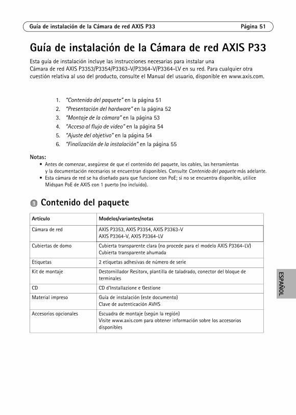
Guía de instalación de la Cámara de red AXIS P33Esta guía de instalación incluye las instrucciones necesarias para instalar una Cámara de red AXIS P3353/P3354/P3363-V/P3364-V/P3364-LV en su red. Para cualquier otra cuestión relativa al uso del producto, consulte el Manual del usuario, disponible en www.axis.com.
Notas:• Antes de comenzar, asegúrese de que el contenido del paquete, los cables, las herramientas
y la documentación necesarios se encuentran disponibles. Consulte Contenido del paquete más adelante.• Esta cámara de red se ha diseñado para que funcione con PoE; si no se encuentra disponible, utilice
Midspan PoE de AXIS con 1 puerto (no incluido).
Contenido del paquete
1. “Contenido del paquete” en la página 51
2. “Presentación del hardware” en la página 523. “Montaje de la cámara” en la página 53
4. “Acceso al flujo de video” en la página 54
5. “Ajuste del objetivo” en la página 546. “Finalización de la instalación” en la página 55
Artículo Modelos/variantes/notas
Cámara de red AXIS P3353, AXIS P3354, AXIS P3363-VAXIS P3364-V, AXIS P3364-LV
Cubiertas de domo Cubierta transparente clara (no procede para el modelo AXIS P3364-LV)Cubierta transparente ahumada
Etiquetas 2 etiquetas adhesivas de número de serie
Kit de montaje Destornillador Resitorx, plantilla de taladrado, conector del bloque de terminales
CD CD d’Installazione e Gestione
Material impreso Guía de instalación (este documento)Clave de autenticación AVHS
Accesorios opcionales Escuadra de montaje (según la región)Visite www.axis.com para obtener información sobre los accesorios disponibles
Página 52 Guía de instalación de la Cámara de red AXIS P33
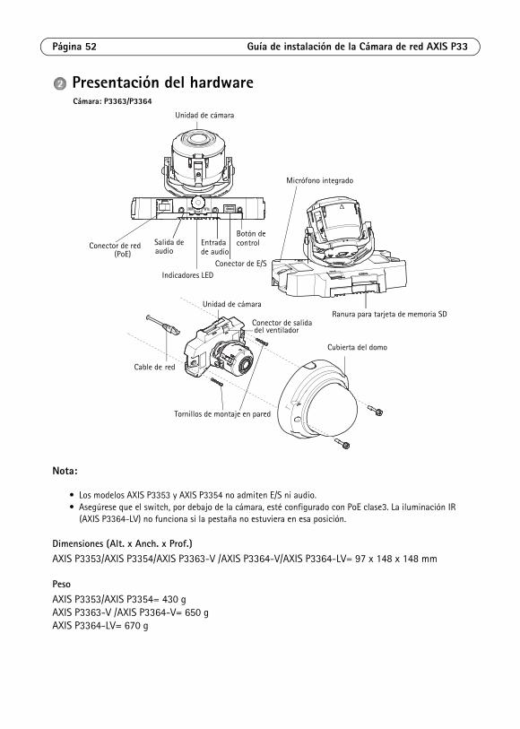
Presentación del hardware
Nota:
• Los modelos AXIS P3353 y AXIS P3354 no admiten E/S ni audio.• Asegúrese que el switch, por debajo de la cámara, esté configurado con PoE clase3. La iluminación IR
(AXIS P3364-LV) no funciona si la pestaña no estuviera en esa posición.
Dimensiones (Alt. x Anch. x Prof.)AXIS P3353/AXIS P3354/AXIS P3363-V /AXIS P3364-V/AXIS P3364-LV= 97 x 148 x 148 mm
PesoAXIS P3353/AXIS P3354= 430 gAXIS P3363-V /AXIS P3364-V= 650 gAXIS P3364-LV= 670 g
Conector de red
Indicadores LED Conector de E/S
(PoE)
Unidad de cámara
Cable de red
Cubierta del domo
audioEntrada
Ranura para tarjeta de memoria SD
Tornillos de montaje en pared
Salida de
Unidad de cámara
Conector de salida del ventilador
Micrófono integrado
Botón de
Cámara: P3363/P3364
de audiocontrol
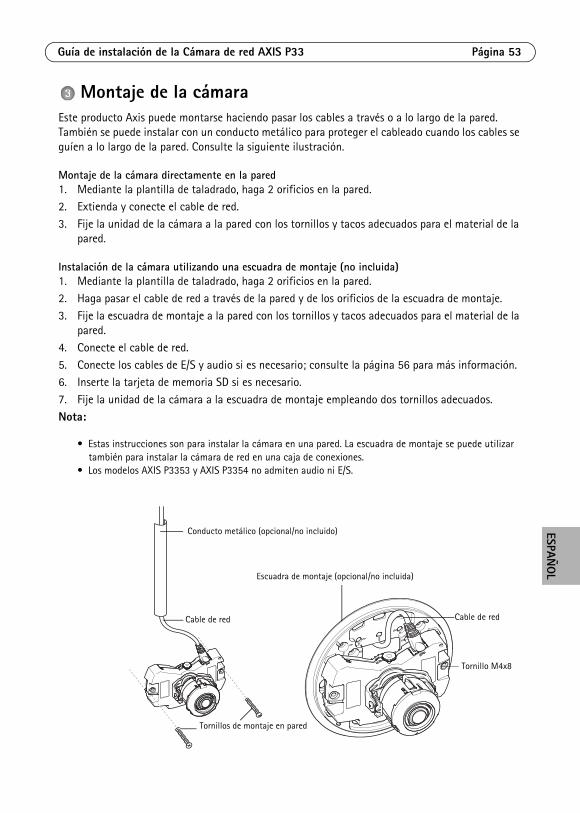
Guía de instalación de la Cámara de red AXIS P33 Página 53
ESPAÑO
L
Montaje de la cámaraEste producto Axis puede montarse haciendo pasar los cables a través o a lo largo de la pared. También se puede instalar con un conducto metálico para proteger el cableado cuando los cables se guíen a lo largo de la pared. Consulte la siguiente ilustración.
Montaje de la cámara directamente en la pared1. Mediante la plantilla de taladrado, haga 2 orificios en la pared.2. Extienda y conecte el cable de red.
3. Fije la unidad de la cámara a la pared con los tornillos y tacos adecuados para el material de la pared.
Instalación de la cámara utilizando una escuadra de montaje (no incluida)1. Mediante la plantilla de taladrado, haga 2 orificios en la pared.2. Haga pasar el cable de red a través de la pared y de los orificios de la escuadra de montaje.
3. Fije la escuadra de montaje a la pared con los tornillos y tacos adecuados para el material de la pared.
4. Conecte el cable de red.
5. Conecte los cables de E/S y audio si es necesario; consulte la página 56 para más información. 6. Inserte la tarjeta de memoria SD si es necesario.
7. Fije la unidad de la cámara a la escuadra de montaje empleando dos tornillos adecuados.
Nota:
• Estas instrucciones son para instalar la cámara en una pared. La escuadra de montaje se puede utilizar también para instalar la cámara de red en una caja de conexiones.
• Los modelos AXIS P3353 y AXIS P3354 no admiten audio ni E/S.
Conducto metálico (opcional/no incluido)
Escuadra de montaje (opcional/no incluida)
Cable de red
Tornillo M4x8
Tornillos de montaje en pared
Cable de red
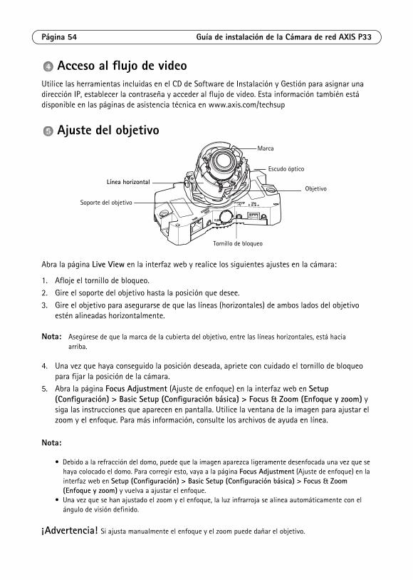
Página 54 Guía de instalación de la Cámara de red AXIS P33
Acceso al flujo de videoUtilice las herramientas incluidas en el CD de Software de Instalación y Gestión para asignar una dirección IP, establecer la contraseña y acceder al flujo de video. Esta información también está disponible en las páginas de asistencia técnica en www.axis.com/techsup
Ajuste del objetivo
Abra la página Live View en la interfaz web y realice los siguientes ajustes en la cámara:
1. Afloje el tornillo de bloqueo.
2. Gire el soporte del objetivo hasta la posición que desee.
3. Gire el objetivo para asegurarse de que las líneas (horizontales) de ambos lados del objetivo estén alineadas horizontalmente.
Nota: Asegúrese de que la marca de la cubierta del objetivo, entre las líneas horizontales, está hacia arriba.
4. Una vez que haya conseguido la posición deseada, apriete con cuidado el tornillo de bloqueo para fijar la posición de la cámara.
5. Abra la página Focus Adjustment (Ajuste de enfoque) en la interfaz web en Setup (Configuración) > Basic Setup (Configuración básica) > Focus & Zoom (Enfoque y zoom) y siga las instrucciones que aparecen en pantalla. Utilice la ventana de la imagen para ajustar el zoom y el enfoque. Para más información, consulte los archivos de ayuda en línea.
Nota:
• Debido a la refracción del domo, puede que la imagen aparezca ligeramente desenfocada una vez que se haya colocado el domo. Para corregir esto, vaya a la página Focus Adjustment (Ajuste de enfoque) en la interfaz web en Setup (Configuración) > Basic Setup (Configuración básica) > Focus & Zoom (Enfoque y zoom) y vuelva a ajustar el enfoque.
• Una vez que se han ajustado el zoom y el enfoque, la luz infrarroja se alinea automáticamente con el ángulo de visión definido.
¡Advertencia! Si ajusta manualmente el enfoque y el zoom puede dañar el objetivo.
Tornillo de bloqueo
Soporte del objetivo
ObjetivoLínea horizontal
Marca
Escudo óptico
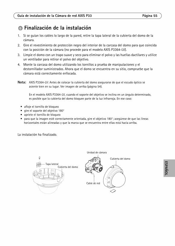
Guía de instalación de la Cámara de red AXIS P33 Página 55
ESPAÑO
L
Finalización de la instalación1. Si se guían los cables lo largo de la pared, retire la tapa lateral de la cubierta del domo de la
cámara.
2. Gire el revestimiento de protección negro del interior de la carcasa del domo para que coincida con la posición de la cámara (no procede para el modelo AXIS P3364-LV).
3. Limpie el domo con un trapo suave y seco para eliminar el polvo y las huellas dactilares y utilice un ventilador para retirar el polvo del objetivo.
4. Monte la carcasa del domo utilizando los tornillos a prueba de manipulaciones y el destornillador suministrados. Ahora que el domo se encuentra en su sitio, compruebe que la cámara está correctamente enfocada.
Nota: AXIS P3364-LV: Antes de colocar la cubierta del domo asegurarse de que el escudo óptico se asiente bien en su lugar. Ver imagen de arriba (página 54).
En el modelo AXIS P3364-LV, cuando el soporte del objetivo se inclina en un ángulo determinado, es posible que la cubierta del domo bloquee parte de la luz infrarroja. En ese caso:
• afloje el tornillo de bloqueo• gire el soporte del objetivo 180°• apriete el tornillo de bloqueo• para que la imagen esté correctamente orientada, gire el objetivo 180°; asegúrese de que las líneas
horizontales están alineadas y que la marca que se encuentra entre ellas está hacia arriba.
La instalación ha finalizado.
Tapa lateralCubierta del domo
Unidad de cámara
Cable de red
Cubierta del domo
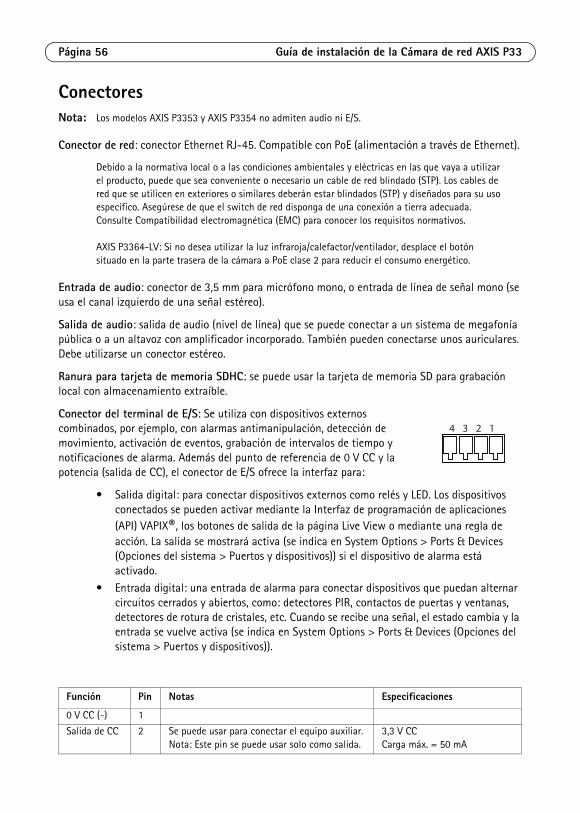
Página 56 Guía de instalación de la Cámara de red AXIS P33
ConectoresNota: Los modelos AXIS P3353 y AXIS P3354 no admiten audio ni E/S.
Conector de red: conector Ethernet RJ-45. Compatible con PoE (alimentación a través de Ethernet).
Debido a la normativa local o a las condiciones ambientales y eléctricas en las que vaya a utilizar el producto, puede que sea conveniente o necesario un cable de red blindado (STP). Los cables de red que se utilicen en exteriores o similares deberán estar blindados (STP) y diseñados para su uso específico. Asegúrese de que el switch de red disponga de una conexión a tierra adecuada. Consulte Compatibilidad electromagnética (EMC) para conocer los requisitos normativos.
AXIS P3364-LV: Si no desea utilizar la luz infraroja/calefactor/ventilador, desplace el botón situado en la parte trasera de la cámara a PoE clase 2 para reducir el consumo energético.
Entrada de audio: conector de 3,5 mm para micrófono mono, o entrada de línea de señal mono (se usa el canal izquierdo de una señal estéreo).
Salida de audio: salida de audio (nivel de línea) que se puede conectar a un sistema de megafonía pública o a un altavoz con amplificador incorporado. También pueden conectarse unos auriculares. Debe utilizarse un conector estéreo.
Ranura para tarjeta de memoria SDHC: se puede usar la tarjeta de memoria SD para grabación local con almacenamiento extraíble.
Conector del terminal de E/S: Se utiliza con dispositivos externos combinados, por ejemplo, con alarmas antimanipulación, detección de movimiento, activación de eventos, grabación de intervalos de tiempo y notificaciones de alarma. Además del punto de referencia de 0 V CC y la potencia (salida de CC), el conector de E/S ofrece la interfaz para:
• Salida digital: para conectar dispositivos externos como relés y LED. Los dispositivos conectados se pueden activar mediante la Interfaz de programación de aplicaciones (API) VAPIX®, los botones de salida de la página Live View o mediante una regla de acción. La salida se mostrará activa (se indica en System Options > Ports & Devices (Opciones del sistema > Puertos y dispositivos)) si el dispositivo de alarma está activado.
• Entrada digital: una entrada de alarma para conectar dispositivos que puedan alternar circuitos cerrados y abiertos, como: detectores PIR, contactos de puertas y ventanas, detectores de rotura de cristales, etc. Cuando se recibe una señal, el estado cambia y la entrada se vuelve activa (se indica en System Options > Ports & Devices (Opciones del sistema > Puertos y dispositivos)).
Función Pin Notas Especificaciones
0 V CC (-) 1
Salida de CC 2 Se puede usar para conectar el equipo auxiliar.Nota: Este pin se puede usar solo como salida.
3,3 V CCCarga máx. = 50 mA
4 3 2 1
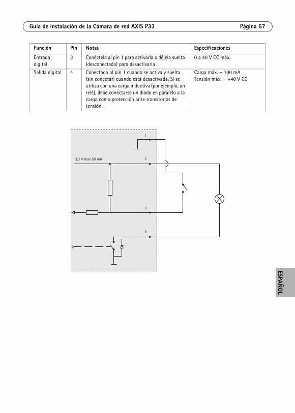
Guía de instalación de la Cámara de red AXIS P33 Página 57
ESPAÑO
L
Entrada digital
3 Conéctela al pin 1 para activarla o déjela suelta (desconectada) para desactivarla
0 a 40 V CC máx.
Salida digital 4 Conectada al pin 1 cuando se activa y suelta (sin conectar) cuando está desactivada. Si se utiliza con una carga inductiva (por ejemplo, un relé), debe conectarse un diodo en paralelo a la carga como protección ante transitorios de tensión.
Carga máx. = 100 mATensión máx. = +40 V CC
Función Pin Notas Especificaciones
3.3 V max 50 mA
1
2
3
4
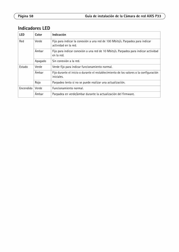
Página 58 Guía de instalación de la Cámara de red AXIS P33
Indicadores LEDLED Color Indicación
Red Verde Fijo para indicar la conexión a una red de 100 Mbits/s. Parpadea para indicar actividad en la red.
Ámbar Fijo para indicar conexión a una red de 10 Mbits/s. Parpadea para indicar actividad en la red.
Apagado Sin conexión a la red.
Estado Verde Verde fijo para indicar funcionamiento normal.
Ámbar Fijo durante el inicio o durante el restablecimiento de los valores o la configuración iniciales.
Rojo Parpadeo lento si no se puede realizar una actualización.
Encendido Verde Funcionamiento normal.
Ámbar Parpadea en verde/ámbar durante la actualización del firmware.
Guía de instalación de la Cámara de red AXIS P33 Página 59
ESPAÑO
L
Restablecimiento de los valores inicialesMediante esta operación se restablecerá la configuración predeterminada original de todos los parámetros, incluida la dirección IP:
1. Desconecte la alimentación de la cámara.
2. Mantenga pulsado el botón de control y vuelva a conectar la alimentación (consulte Presentación del hardware en la página ).
3. Mantenga pulsado el botón de control durante 15 segundos hasta que el indicador de estado parpadee en color ámbar.
4. Suelte el botón de control. El proceso finalizará aproximadamente en 1 minuto (cuando el indicador de estado se ilumine en color verde). La cámara de red habrá recuperado los valores iniciales. La dirección IP predeterminada es 192.168.0.90.
5. Vuelva a asignar la dirección IP.
6. Vuelva a enfocar la cámara.
También es posible restablecer los parámetros a los valores iniciales mediante la interfaz web. Vaya a Setup (Configuración) > System Options (Opciones del sistema) > Maintenance (Mantenimiento).
Más informaciónEl manual del usuario está disponible en el sitio web de Axis en www.axis.com.
Para obtener más información sobre los productos y tecnologías de Axis, visite www.axis.com/academy, centro de formación mundial para el vídeo en red.
Un consejo:Visite www.axis.com/techsup para comprobar si hay disponible firmware actualizado para su producto de Axis. Para consultar la versión de firmware que tiene instalada actualmente, vaya a Setup (Configuración) > About (Acerca de) en la interfaz web.
GaranziaPer informazioni relative alla garanzia del prodotto AXIS ed ogni altra ulteriore informazione correlata, si prega di consultare la pagina http://www.axis.com/warranty


Installation Guide Ver.2.3
AXIS P33 Network Camera Series Printed: June 2014
© Axis Communications AB, 2012-2014 Part No. 58438