Embed Size (px)
Citation preview

Header1 copy 2015 deValirian
deValirian DV0 HEADER1
Battery shield for Raspberry Pi and DV0 expansion
boards controller Features Power supply for Raspberry Pi A and B models
Wide input voltage for battery or wall adapter
Safe shutdown for Linux operating system
Battery voltage monitoring
Real time clock keeping
Programmable wake up scheduling
Programmable hardware restart
Programmable shutdown and boot time
Watch dog reset function
OnOff Push button for manual or remote power
updown sequences
DV0 bus connector for expansion boards
Free available Linux commands and API library
(Python C++ or Java) for setting parameters and
accessing expansion boards
Shape designed for easy access to Raspberry Pi
GPIO DSI and CSI Camera connectors
Spacers and screws for mechanical assembly are
included
Technical specifications Power to Raspberry Pi 5V 08A
Power to DV0 expansion bus 5V 1A
Both 5V outputs are short circuit protected
Input voltage for battery or wall adapter from 65V
up to 27V
Both wall adapter and battery connector protected
against wrong polarity connection
Battery chemistry NiMH or Lead-Acid
Battery slow charge internal resistor
Connector for increasing battery charge current
Power consumption during sleep (all 5V power
supplies off) 35mA
Programmable voltage failure threshold
Selectable mode wall or mode battery standalone
Real time clock accuracy001
Up to 16 expansion boards management capability
Command latency from user application to IO
expansion boards 15ms
Fig 1 Simplified block diagram
IO expansion
boards
OnOff
Battery input
Wall input
External Battery charge resistor
5V
5V
Power
control
unit
DV0 expansion bus
LINUX dv0_manager
PythonJavaC++ API
Usr App Usr App
Shutdown
Set date
dv0_test
HEADER1 Raspberry Pi copy AB Model
DVO HEADER1
Header1-Page 2 copy2015 deValirian
Table of contents
1 Functional overwiew 5
11 Uninterruptible power supply 5
111 Wall Mode vs Battery Mode 5
112 Power Off Conditions 5
113 Power Off Process 6
114 Power On Conditions 6
115 Power On Process 6
116 On State features 6
117 Real time clock 6
12 Managing DVO IO expansion boards 7
121 Discovery process 7
2 Electrical characteristics 8
21 Identifying connectors 8
211 Wall input 8
212 Battery charge resistor 8
213 Battery input 8
214 OnOff Pushbutton 8
215 DV0 Bus connector 9
22 Absolute maximum ratings 10
23 Power Consumption 10
231 Wall input consumption 10
232 Battery input consumption 10
233 Power calculation examples 11
24 DVO Bus length 13
241 Data transmission degrading 13
242 Voltage drop 13
3 Battery dimensioning 15
31 Battery considerations 15
311 Battery chemistry 15
312 Battery capacity 16
313 Internal resistance 16
32 Wall Mode 16
321 Battery capacity calculation procedure 16
DVO HEADER1
Header1-Page 3 copy2015 deValirian
322 Battery charge calculation procedure 17
33 Battery mode 17
331 Battery capacity calculation procedure 18
332 Battery charge calculation procedure 18
34 Battery dimensioning examples 18
341 Wall mode calculations example 18
342 Battery mode calculations examples 19
4 Software 22
41 Architecture description 22
42 dv0_manager installation 23
421 dv0_manager return values 23
422 Unblocking ttyAMA0 23
43 dv0_manager command line parameters 24
431 Parameter -serial_port ltportgt 24
432 Parameter -port ltport numbergt 24
433 Parameter -ip_address ltip_addressgt 24
434 Parameter -login ltlogin namegt 24
435 Parameter -shutdown_command ldquoltcommandgtrdquo 24
436 Parameter -shutdown_time ltsecondsgt 24
437 Parameter -boot_time ltsecondsgt 24
438 Parameter -restart_time ltminutesgt 25
439 Parameter -min_voltage ltvoltagegt 25
4310 Parameter -cut_vbus 25
4311 Parameter -no_push_active 25
4312 Parameter -force_date 25
4313 Parameter -start_up_time ddhhmm 25
4314 Parameter -watch_dog ltsecondsgt 25
44 dv0_test command line parameters 26
441 Parameter -ip_address ltip addressgt 26
442 Parameter -port ltPort numbergt 26
443 Parameter -login ltlogin namegt 26
444 Parameter -password ltpasswordgt 26
445 Parameter -set_date 26
446 Parameter -set_restart_time ltminutesgt 26
447 Parameter -power_off 26
448 Parameter -get_manifest ltaddressgt 26
449 Parameter -watch_dog_reset 27
DVO HEADER1
Header1-Page 4 copy2015 deValirian
4410 Return values of dv0_test 27
45 Examples of dv0_manager dv0_test and Linux scripts 28
46 DV0 API 30
461 Creating an instance of DV0 class 30
462 Connecting to dv0_manager 31
463 API functions related to Header1 32
464 API examples 35
5 Mechanical drawings 39
6 Accessories 40
Important notice 41
Revision history
V10 Jan-2015
DVO HEADER1
Header1-Page 5 copy2015 deValirian
1 FUNCTIONAL OVERWIEW
The DeValirian Header1 is a dual source power
supply for Raspberry Pi providing two functions
Uninterruptible power supply with controlled Linux
shutdown and programmable restart features
Managing DVO InputOutput expansion boards
11 Uninterruptible power supply
As an uninterruptible power supply the Header1
generates stabilized 5V to the Raspberry Pi from the
Wall input or the Battery input whichever is greater
The Header1 control unit communicates to a program
running in the Raspberry Pi Linux (dv0_manager)
which is responsible for issuing a shutdown command
when the Wall input voltage falls below the Battery
input voltage or when the Battery input voltage falls
below a programmable threshold Thus file system
corruption due to sudden power outage can be
avoided
The Header1 control unit communicates with the free
dv0_manager program running in the Raspberry Pi
Linux using the serial channel ttyAMA0 This channel
can be found in the Raspberry expansion connector
See Section 40 for more information about
dv0_manager installation and features
111 Wall Mode vs Battery Mode
The Header1 can react in two ways when the power
in the Wall input disappears depending on the state
of the jumper JP1 See Fig 2 to locate this jumper
When this jumper is closed (Wall Mode) the Header1
control unit issues a shutdown command to the
Raspberry Pi board whenever the voltage on the Wall
Input is lower than the voltage in the Battery Input for
more than five seconds In this mode the battery size
is dimensioned for powering the Raspberry Pi just
during the shutdown time (20 to 30 seconds)
The Wall Mode is intended for applications where the
main power source comes from a wall adapter supply
and a battery is needed only for safe shutdown
purposes or sleeping features as time keeping
scheduled restart onoff pushbutton etc
When JP1 is left open (Battery Mode) the shutdown
command is issued only when the Battery input
voltage falls below min_voltage for more than five
seconds no matters what voltage is at Wall input The
default voltage level for min_voltage is 6V but other
values can be set programmatically to accommodate
a wide range of battery voltages
The Battery Mode is intended for applications where
the main power source is a battery and Wall Input is
used just for slow battery charging or for feeding the
board when the battery needs to be temporally
disconnected
The 5V power to Raspberry Pi is always obtained
from the input source that exhibits the upper voltage
value and automatic balance is made when one
source falls below the other one without affecting the
stability of Raspberry Pi power supply
Every time the Header1 control unit sends a shutdown
command it starts a timer and when it reaches
shutdown_time the 5V power to Raspberry Pi and
DV0 Buscopy as well are disconnected During this time
no power decisions are taken Also when start
conditions are reached another timer is launched and
no power decisions are taken until this timer reaches
boot_time This ensures that safe halt and safe boot
process can be done by the Linux independently of
power fluctuations Both shutdown_time and
boot_time parameters can be set programmatically
as described in Section 4
112 Power Off Conditions
Conditions that trigger a Power Off Process when the
Header1 is at the On State are
V(Wall input) lt 6 for more than 5 seconds when
Wall Mode is selected
V(Battery input) lt min_voltage for more than 5
seconds when Battery Mode is selected
Push button is pressed for more than 4 seconds
(unless that -no_push_active parameter is set)
A SIGPWR is sent to dv0_manager
The PowerOff() API function is called by an
application connected to dv0_manager
Watch dog reset timeout when parameter -
watch_dog ltwatch_dog_timegt has been set and
no watch dog reset has been issued for
watch_dog_time second (see Section 4 for more
information)
Fig 2 JP1 WallBattery mode jumper selector
DVO HEADER1
Header1-Page 6 copy2015 deValirian
113 Power Off Process
The Power Off Process starts when one of the Power
Off Conditions becomes true The sequence of steps
of this process is
Issue a shutdown command to dv0_manager
witch calls the Linux command ldquoshutdown ndashh nowrdquo
Cut off the voltage in the DV0 Bus if parameter -
cut_vbus is set
Wait for shutdown_time seconds
Cut off the voltage of Raspberry Pi and DV0 Bus
Go to Sleep State
114 Power On Conditions
Conditions that trigger a Power On Process when the
Header1 is at the Sleep State are
V(Wall input) gt 62V for more than 5 seconds
when Wall Mode is selected
V(Battery input) gt min_voltage+02 for more than
5 seconds when Battery Mode is selected
Push button is pressed for more than 2 seconds
(unless that -no_push_active parameter is set)
Restart timer timeout when -restart_time
lttime_to_restartgt has ben set and time_to_restart
minutes have been passed until the last arriving to
Sleep State
Scheduled start parameter star_up_time
matches the current date and time kept by
Header1 (see Section 4)
115 Power On Process
The Power Off Process starts when one of the Power
On Conditions becomes true The sequence of steps
of this process is
Rise Raspeberry Pi voltage and DV0 bus voltage
to 5V
Wait boot_time seconds
Send the kept date and time to dv0_manager if
parameter -force_date has been set which sets
system time
Executes the Discovery Process
Go to On State
116 On State features
When the Header1 is in the On State it accepts the
following commands
Set current date and time
Set restart time (restart_time)
Set scheduled start (start_up_time)
Reset watch dog timer if enabled
Route commands tofrom DVO bus expansion
boards
The Figure 3 shows the Header1 states and their
transitions
117 Real time clock
The Header1 board keeps the date and time during
both On and Sleep states It starts at 112001
000000 on the First Wake Up and can be set to any
value by using the free program dv0_test or by calling
the API function SetDate()
The accuracy of the Header1 real time clock is 001
which is not a good long term accuracy because it
means that the time error over 24 hours can be up to
1 minute and 20 seconds (it depends on ambient
temperature)
However this accuracy is good enough to starts the
board at scheduled time and to give an initial date to
the Raspberry Pi With this initial date the Linux OS
can take decisions and with relaxed periodicity get
access to Internet looking for a NTP server and to
synchronize itself and the Header1 board
Fig 3 Header1 states and transitions
First wake
up
Sleep
State
Power On
Process
Power Off
Process
On
State
Power On
Condition
Power Off
Condition
All power
sources off
DVO HEADER1
Header1-Page 7 copy2015 deValirian
12 Managing DVO IO expansion boards
DVO IO Expansion boards allow Linux based systems
to gain access of the real word by giving easy control
of physical inputs and outputs like analog or digital
sensors relays stepper motors servo motors
keyboard displays etc
These boards need a 5V power supply and a RS422
twisted pair serial channel connected in parallel bus
mode Thanks to the address selector micro-switch
located at each IO board the header can send data
and poll information from every board connected to
the bus
After the First Wake Up state the Header1 control
unit executes the initial discovering process by
individually polling to all possible address It takes
roughly one second and once it is finished the
Header1 board knows how many boards are
connected and what their address are
User programs can readwrite data fromto boards
thanks to dv0_manager program which acts as a
tunnel between user programs and IO boards A
complete and easy to use library is free available for
CC++ Java and Python See Section 4 for more
information and examples
So user programs connect to dvo_manager which
talks with the Header1 control unit the actual
responsible for send and receive data through the
serial channel During idle states that is when user
programs donrsquot invoke any library function the
Header1 control unit continuously polls to all known
board to get the value of their inputs and maintains a
local database with these values Thanks to this
database user programs functions that want to read
boardrsquos input values exhibit no extra delay
independently of how many boards are connected
Also user program functions that want to write to a
specific board are considered as a high priority
procedure by the Heade1 control unit and it only wait
the current poll operation to launch the command to
the specified board This strategy ensures a
maximum latency of 15 ms both for read and write
operations from user programs
121 Discovery process
The broad discovery process that is a sequential
enquiry to all possible 63 address is made whenever
The First Wake up occurs
Every time that the Header1 goes to On State
from Idle State
An individual discovery process that is an enquire to
a unique and specific address is made whenever a
user program wants to access to a board that is not
present in the Header1 control unit database In order
to maintain the latency time declared above the
control unit returns an error as ldquoBoard not presentrdquo to
the user program function but simultaneously sends
a poll to this board If this board is really connected
the next user program function to this board will be
successful
This allows a ldquohot connectionrdquo feature for the DV0 Bus
but the user program procedure has to check every
function return value and in case of ldquoBoard not
presentrdquo error retry the function call instead of
treating this error as an exception
DVO IO Board 1
DVO IO Board 2
DVO IO Board 16
Address Address Address
DVO IO Board 1
Fig 4 DVO IO expansion board bus
hellipup to 16 boardshellip
Serial channel twisted pair
5Volts1A
0V
DVO HEADER1
Header1-Page 8 copy2015 deValirian
2 ELECTRICAL CHARACTERISTICS
This section explains the electrical characteristics of
each Header1 connector and the length issues related
to the DV0 bus cabling
21 Identifying connectors
The Figure 5 shows the location of all connectors of
Header1 board
211 Wall input
Main Input power for generating Raspberry Pi 5V
DV0 Bus 5V and battery charge Connect the positive
wire to the screw marked as ldquo+rdquo and the negative wire
to the screw marked as ldquo-ldquo
Maximum Voltagehelliphelliphelliphelliphelliphelliphelliphelliphelliphelliphelliphelliphellip27V
Minimum Voltagehelliphelliphelliphelliphelliphelliphelliphelliphelliphelliphelliphelliphellip65V
Reverse polarity protectionhelliphelliphelliphelliphelliphelliphelliphelliphelliphellipYes
SolidStranded wirehelliphelliphelliphelliphelliphellipAWG 16 to AWG 24
Wire cross section helliphelliphelliphelliphelliphelliphellip15mm to 02mm
See 23 Power Consumption for input current
calculation
212 Battery charge resistor
This connector is intended for increase the battery
charge current by connecting an external resistor See
34 Battery dimensioning and charging
213 Battery input
Secondary input power for generating Raspberry Pi
5V DV0 Bus 5V and battery charge Connect the
positive wire to the screw marked as ldquo+rdquo and the
negative wire to the screw marked as ldquo-ldquo
Maximum Voltagehelliphelliphelliphelliphelliphelliphelliphelliphelliphelliphelliphelliphellip27V
Minimum Voltagehelliphelliphelliphelliphelliphelliphelliphelliphelliphelliphelliphelliphelliphellip6V
Reverse polarity protectionhelliphelliphelliphelliphelliphelliphelliphelliphellipYes
SolidStranded wirehelliphelliphelliphelliphellipAWG 16 to AWG 24
Wire cross section helliphelliphelliphelliphelliphelliphellip15mm to 02mm
See 23 Power Consumption for input current
calculation
214 OnOff Pushbutton
A momentary pushbutton connected to this input
allows to rise the 5V power for the Raspberry Pi and
the DV0 Bus connecter if it is pressed for more than 2
seconds Also a Power Off Process should be
initiated if the button is pressed for more than 4
seconds
The operation of this input is disabled if the
dv0_manager program is called with the command
line parameter ndashno_push_active
This input has an internal 10K pull up resistor
connected to the 33 V Header1 rail If a device other
than a pushbutton is connected to this input keep in
mind that the Header1 control unit requires a voltage
below 660mV so a minimum of 300μA sink current
needs to be assured The screw aligned with the text
ldquoOFFrdquo is connected to the common ground Wall and
Battery ldquo-ldquo inputs and 0V of DV0 Bus
No high voltage transients protection are placed so it
is not recommended to assert a large cable between
this input and the pushbutton if this cable can be
placed in parallel with noisy or high voltage power
lines
Wall Input
Battery charge
resistor
Battery Input
Raspberry Pi
Connectors top
amp bottom
OnOff
Pushbutton
DVO BUS
Fig 5 Header1 connectors
DVO HEADER1
Header1-Page 9 copy2015 deValirian
215 DV0 Bus connector
This receptacle connector contains power and data
for IO expansion board An extracting socket with
screws is supplied with the Header1 board to facilitate
the installation of IO expansion board bus cabling
(AWG 1624 cross section 15 to 02 mm)
Technical data
Socket reference 20020004-D041B01LF from
FCI
SolidStranded wire AWG 16 to AWG 26
Wire cross section 15mm to 02mm
Data signal A and B ESD EFT and Surge
protection IEC 61000-4-2 (ESD) IEC 61000-4-4
(EFT) and IEC 61000-4-5 (Surge)
5V output maximum current 1A
5V output short-circuit current 2A
Connect differential pair A to all A inputs of connected
IO boards and pair B to all B inputs as well Also
connect the common data pin (0V) to all IO boards
The output marked as 5V is the DV0 bus voltage
output It is raised to 5V during the Power On
Process and disconnected during the Power Off
Process (see 115 and 113) This output can be
used to fed the IO boards connected to the bus but it
is not mandatory since IO boards can be locally
supplied as explained at 242 Voltage drop
All IO Boards PCB are marked with the legend shown
at Figure 7
5V
0V
B
A
DV0 Bus voltage
power supply Differential pair wire B
Differential pair wire A
Common for data and
power
Fig 7 DVO Bus connector pin out
DVO HEADER1
Header1-Page 10 copy2015 deValirian
22 Absolute maximum ratings
Absolute maximum ratings for the Header1 board are
listed below Exposure to these maximum rating
conditions for extended periods may affect device
reliability Functional operation of the device at these
or any other conditions above the parameters
indicated in the operation listings of this specification
is not assured
Operating Ambient temperaturehelliphelliphellip0degC to +70degC
Storage temperature -55degC to +125degC
Voltage on Wall Input-28V to +280V
Voltage on Battery Input-28V to +280V
Voltage on Pushbutton connector-03V to +33V
Maximum Current out to Raspberry Picopyhelliphelliphelliphellip1A
Maximum Current out to DV0 Bushelliphelliphelliphelliphelliphellip12A
Stresses above those listed under ldquoAbsolute
Maximum Ratingsrdquo may cause permanent damage to
the device This is a stress rating only and functional
operation of the device at those or any other
conditions above those indicated in the operation
listings of this specification is not implied Exposure to
maximum rating conditions for extended periods may
affect device reliability
23 Power Consumption
Either in Wall Mode or Battery Mode the power flows
from the Wall input or the Battery input depending
only on what input has the higher level of voltage
Because of a diode connection when the higher input
falls below the lower the Header1 softly balances the
path of power so that the output to the Raspberry Pi
the DVO Bus and the internal power doesnrsquot note the
change
Figure 7 shows a simplified diagram of power path
The power consumption is the product of voltage and
current so given a nominal voltage for wall or battery
input as a design decision the input current has to be
calculated for dimensioning the wall input adapter and
the capacity of the battery
231 Wall input consumption
To do that lets begin with the total power equation of
Wall input
Pwall = Prasp+PDV0+Pcontrol+Pdiode+Pcharge
Prasp is the power delivered to the Raspberry Pi plus
the amount of losses due to the inefficiency of the
step down voltage regulators As its efficiency is
roughly 80 per cert Prasp can be expressed as
Prasp = 5 x IRasp 08
The same reasoning applies for PDV0
PDVO = 5 x IDVO 08
Pcontrol is the power that needs the Header1 control
unit to operate and is quite different whether this
control unit is in the sleep state or in the off state
During on state the current consumption is 25mA
while in the sleep state this current falls to 35mA The
control unit voltage regulator is a linear regulator so
the current delivered is constant which yields a power
consumption of
Pcontrol = Vwall x Icontrol
Pdiode is the loss of power due to the balancing diodes
and can be computed as the sum of the input current
to VRasp and VDVO step down regulators and the
control current all multiplied by 04 as the diode
nominal voltage drop
Pdiode = 04(PraspVwall + PDV0Vwall + Icontrol)
Finally Pcharge depends on the difference of voltage
between Wall input and Battery input and the charging
resistor Assuming a diode voltage drop of 02V this
power can be computed as
Pcharge = Vwall (Vwall - Vbat - 02)Rchrg
The charge resistor depends on the capacity of the
battery and the time required to obtain a full charge
condition If no external resistor is applied the charge
resistor value is 470Ω
232 Battery input consumption
The power equation of Battery input is only slightly
different of the Wall input in the sense of that no
power charging is involved
Pbattery = Prasp+PDV0+Pcontrol+Pdiode
And the expressions for Pcontrol and Pdiode are
Wall input
Vwall Iwall
Battery
input
Vbat Ibat
Step down 80
efficiency
Step down 80
efficiency
5V Raspberry IRasp
IDV0
IControl Header1 control
unit
RC
hrg
I chrg
Fig 7 Power path
5V DVO
5V DV0
DVO HEADER1
Header1-Page 11 copy2015 deValirian
Pcontrol = Vbat x Icontrol
Pdiode = 04(PraspVbat + PDV0Vbat + Icontrol)
Note that the power needed to feed the Header1 control unit is proportional to the battery voltage so in terms of battery duration the lower the battery voltage the better the battery performance
233 Power calculation examples
In the formula expressed above there are parameters that are design decisions as Wall input voltage and Battery input voltage some constants like Icontrol or Rchrg and some parameters that can be estimate like IRasp and IDVO
The target is to obtain Iwall and Ibat to calculate the
power of the Wall adapter and the capacity of the
battery
The value of constants parameters are
Icontrol(On state)helliphelliphelliphelliphelliphelliphelliphelliphelliphelliphelliphelliphellip0025A
Icontrol (Off state)helliphelliphelliphelliphelliphelliphelliphelliphelliphelliphellip00035A
Rchrg (no external resistor)helliphelliphelliphelliphelliphelliphelliphelliphelliphellip470Ω
As for estimated parameters IDVO is obtained as the
sum of all boards current easily available in the data
sheet of every board On the other hand IRasp is quite
difficult to estimate because it is function of how many
USB gadgets are connected Ethernet traffic (if exists)
camera consumption Linux distro etc
However it is possible to estimate the average
current consumption of IRasp assuming the following
data (source official Raspberry site)
Raspberry Picopy A nominal consumptionhelliphelliphellip05A
Raspberry Picopy B nominal consumptionhelliphelliphellip07A
Camera consumptionhelliphelliphelliphelliphelliphelliphelliphelliphelliphelliphellip02A
And for each gadget connected to USB try to find out
their power consumption (in Watts) and divide it by 5
to obtain the current consumption (in Amperes) and
add it to the value of IRasp
Note that all values have to be expressed in Volts
Amperes and Watts to avoid magnitude
Following examples will be used for power calculation
and for battery
Example 1
Set Wall input to 15V Battery input to 12V no
external charge resistors Raspberry Pi A model with
no camera and two IO_A boards connected to the
bus
Lets begin with the on state power consumption From
the data described above calculate PRasp
Prasp = 5 x 05 08 = 312 [W]
From IO_A datasheet find out the maximum current
consumption (0134A) and calculate PDVO
PDVO = 5 x (0134 + 0134) 08 = 1675 [W]
Continue with the control unit power using the greater
voltage among Wall or Battery input In normal
operation conditions voltage at Wall input is greater
than Battery input Only in the absence of Wall power
will be the Battery input get the greater value
Pcontrol = Vwall x Icontrol = 15 x 0025 = 0375 [W]
Then compute Pdiode
Pdiode = 04(PraspVwall + PDV0Vwall + Icontrol) =
04(31215+167515+0025) = 0138 [W]
Follow with Pcharge
Pcharge = Vwall (Vwall - Vbat - 02)Rchrg =
= 15(15-12-02)470 = 0006 [W]
And finally add altogether to carry out the total power
Pwall = Prasp+PDV0+Pcontrol+Pdiode+Pcharge = 312 + 1675
+ 0375 + 0138 + 0006 = 531 [W]
With this information it is possible to find a suitable
wall adapter but sometimes adapters are rated by
their output current instead of their output power In
this case simply divide the calculated power by the
nominal voltage
Iwall = Pwall Vwall = 53115 = 0354 [A]
As for the battery it is important to know the power
consumption during both the on state and the off
state
During the on state battery power is
Pbattery(ON) = Prasp+PDV0+Pcontrol+Pdiode
where
Pcontrol(ON) = Vbat x Icontrol(ON) = 12 x 0025 = 03 [W]
Pdiode(ON) = 04(PraspVbat + PDV0Vbat + Icontrol(ON)) =
04(31212+167512+0025) =0170 [W]
then
Pbattery(ON) = Prasp+PDV0+Pcontrol(ON)+Pdiode(ON) =
= 312 + 1675 + 03 + 017 = 526 [W]
DVO HEADER1
Header1-Page 12 copy2015 deValirian
and dividing by Vbat to obtain Ibat current yields
Ibat(ON) = Pbattery(ON)12 = 0439 [A]
During the off state battery power is
Pbattery(OFF) = Pcontrol(OFF)+Pdiode(OFF)
because no energy is supply to the board or the bus
The power loss on the diode is
Pdiode(OFF) = 04 x Icontrol(OFF) = 04 x 00035 = 00014
[W]
and power control is reduced to
Pcontrol(OFF) = Vbat x Icontrol(OFF) = 12 x 00035 = 0042 [W]
Total power is
Pbattery(OFF) = Pcontrol(OFF)+Pdiode(OFF) = 0042 + 00014 =
0043 [W]
Dividing by Vbat to obtain Ibat current
Ibat(OFF) = Pbattery(OFF)12 = 00036 [A]
Dealing with batteries it is usual to manage nominal
voltage and discharge current as a design parameters
to compute the battery size and estimations on battery
duration and charging time as well Both IBat(OFF) and
Ibat(ON) will be used at 3 Battery dimensioning
Example 2
Set Wall input to 12V Battery input to 72V no
external charge resistors Raspberry Pi B model with
camera a WiFi dongle which has a rated power of
200mW and four IO_A boards connected to the bus
The current drown by the Raspberry Pi in this case is
Irasp = 07 + 02 + 025 = 0940 [A]
and the power
Prasp = 5 x 0940 08 = 587 [W]
Using the same sources of information that on the
example 1 it is easy to find
PDVO = 5 x (4 x 0134) ) 08 = 335 [W]
Pcontrol = Vwall x Icontrol = 12 x 0025 = 03 [W]
Pdiode = 04(PraspVwall + PDV0Vwall + Icontrol) =
04(58712+33512+0025) = 0317 [W]
Pcharge = Vwall (Vwall - Vbat - 02)Rchrg =
= 12(12-72-02)470 = 0006 [W]
And finally
Pwall = Prasp+PDV0+Pcontrol+Pdiode+Pcharge = 587 + 335
+03 + 0317 + 0006 = 984 [W]
Iwall = Pwall Vwall = 98412 = 0820 [A]
As for the battery during the on state the
intermediate values are
Pcontrol(ON) = Vbat x Icontrol(ON) = 72 x 0025 = 0180 [W]
Pdiode(ON) = 04(PraspVbat + PDV0Vbat + Icontrol(ON)) =
04(58772+33572+0025) =0522 [W]
then
Pbattery(ON) = Prasp+PDV0+Pcontrol(ON)+Pdiode(ON) =
= 587+ 335 + 018 +0522 = 992 [W]
and dividing by Vbat to obtain Ibat current yields
Ibat(ON) = Pbattery(ON)72 = 138 [A]
During the off state the intermediate values are
Pdiode(OFF) = 04 x Icontrol(OFF) = 04 x 00035 = 00014
[W]
Pcontrol(OFF) = Vbat x Icontrol(OFF) = 72 x 00035 = 0025
[W]
then
Pbattery(OFF) = Pcontrol(OFF)+Pdiode(OFF) = 0025 + 00014 =
0026 [W]
Dividing by Vbat to obtain Ibat current
Ibat(OFF) = Pbattery(OFF)72 = 00036 [A]
Note that although the Ibat(OFF) of example 1 and
example 2 are similar the power of example 2 is
reduced proportionally to the reduction of battery
nominal voltage So to maximize the duration of the
battery during off state it is better to choice a low
voltage battery
DVO HEADER1
Header1-Page 13 copy2015 deValirian
24 DVO Bus length
There are two different considerations about DV0 Bus
wire length On one hand there is the data
transmission degrading on the other hand there is the
issue of the voltage drop due to the resistance of the
cable
241 Data transmission degrading
Data is transmitted using a RS422 standard level of
differential voltage at 100kbps on the wires marked as
A and B at the DV0 Bus connector This standard
doesnrsquot define a wire type to be used in opposition to
other standards like Ethernet or similar For this
reason there is not an official maximum cable length
for this standard
However there are a conservative data based on
empirical test that assures a 1000 meters length at
100 kbsp using a twisted pair of 15pf 5nsm of
propagation speed
To achieve the maximum noise rejection that RS422
offers it is mandatory to use a twisted pair We
recommend a twisted pair of AWG 20 (05 mm2)
because test realized with this cable had shown no
degradation over 50 meters bus with 16 IO boards
connected (no termination resistors are required for
that distance)
Even with the CRC that protects all frames which
travel through the bus and despite the excellent
performance shown over 50 meters bus length we
donrsquot recommend to exceed this limit due to the
ground common mode noise that could appear if the
power wires of bus are not strong enough or there is a
ground loop
The common mode noise is generated by the power
current when it flows throughout the power wires As
the power wires donrsquot have a zero impedance a
common voltage appears (see Figure 8) and if this
noise is greater than 7 volts the receiver canrsquot decode
data so the current frame will be ignored Also all
strong electric or magnetic field close to the power
wires can induce a common mode voltage as well
To reduce the common mode voltage noise it is
strongly recommended
Twist the power wires as the data wires This
reduces the inductive factor of impedance and the
magnetic fields disturbance
Avoid cabling power wires in parallel with other
power lines specially if they carry strong inductive
loads as motors or electro valves
242 Voltage drop
The voltage drop across the power wires is due to the
DC impedance (ie the resistance) of these wires It
is easy to calculate this voltage drop average value
knowing the section of the cable its length and the
average current consumption of the IO board
Knowing the section of the cable manufacturers
report its resistivity (ρ) in ohmsmeter Then to obtain
the voltage drop
Vdrop = Iavg x length x ρ
Using the example 2 explained above with AWG 20
section and 25 meters length between the Header1
board and the IO board the voltage drop will be
Vdrop = Iavg x length x ρ = 4 x 0134 x 25 x 0033 =
0442 [V]
In the above expression the figure 0033 is the
nominal resistivity of AWG 20 wire (from
manufacturer) As all DVO IO boards can withstand
this voltage drop over 5V this example is correct
However this voltage drop is near the limits so if we
plan a larger bus length a new approach is needed
To solve this issue there are two solutions available
Increase the wire section
Feed IO board with local power supplies
Increasing the wire section is the simplest solution but
sometimes is not practical due to the cost increment
and the difficulty of cabling thick wires on the small
connectors of IO boards
The use of local power supplies offers more flexibility
and solves the problem of connecting heavy loads (as
motors or servos) to the DV0 Bus power
Figure 9 shows this 3-wires approach When using
local powering no high current flows through the
ground line but there is the risk of creating a ground
loop due to the difference of potential between the
earth reference of the local power supplies However
the common mode voltage generated in this case is
far lower than the one due to power supply current
Vcm = Z x Ipwr
5V
0V
Ipwr
Fig 8 Common mode noise
Z
DVO HEADER1
Header1-Page 14 copy2015 deValirian
Header1 and DV0 IO boards are protected against high transient voltage according to IEC 61000-4-5 but it is not recommended to deploy a large length of cable with different earths references lighting can generate a sudden high energy transient that would destroy the transceivers despite the surge protections
This approach is intended just to avoid large currents flowing through the power lines not to increase the distance between Header1 and IO board If you want to do it at your risk but at least add a more powerful TVS protection and assure a good earth connection at both power supplies Also it is strongly recommended to avoid placing data lines close to power lines
CAUTION
Z
5V
5V
Ve
Ie
Vcm = Ie x Z
Fig 9 Local powering and ground loop
DVO HEADER1
Header1-Page 15 copy2015 deValirian
3 BATTERY DIMENSIONING
The Header1 board is intended for two battery
scenarios
Wall Mode The system is powered by a wall
adapter and the battery is dimensioned only for
assuring a clean shutdown
Battery Mode The system is mainly powered by
a wall adapter but in case of failure the system
continues its operation powered by the battery
until the voltage battery drops below a save
preconfigured value witch allows a clean
shutdown
Obviously the second scenario requires a much
powerful battery than the first one
Following in this section an explanation of how to
estimate the battery capacity will be given along with
some discussions on the most suitable types of
batteries and their nominal voltage Also it is
important to calculate the optimum value for the
charging resistor However prior of battery
calculation it is worth to comment some issues
related to battery chemistry and capacity
31 Battery considerations
In this document all references to ldquobatteryrdquo stand for
ldquorechargeable batteryrdquo For our purposes
rechargeable batteries are defined by three
parameters
Chemistry Can be Nickel based Lead based or
Lithium based
Capacity Indicates the amount of energy that the
battery can store
Internal resistance The great the internal
resistance the lower the current that can be
drown from the battery
311 Battery chemistry
Lithium base batteries requires a smart charge
system The Header1 board DOESNrsquoT HAVE A
SMART CHARGE SYSTEM so Lithium based
batteries are FORBIDEN to Header1
Nickel based batteries are nowadays only Nickel-
Metal Hydride chemistry because the ancient Nickel
Cadmium technology has become prohibited This
batteries are robust easy to charge if the current is
not great better ratio capacityweight and
capacityvolume than lead batteries but much
expensive
Lead battery are also robust and easy to charge
cheaper than Nickel batteries but they need much
volume and their weight is important
As a rule of thumb when in battery mode if there is
no restriction about volume and weight the better
decision is a lead battery More exactly we
recommend sealed lead acid because they are
maintenance-free and their price is very attractive
However during the last years NiMH batteries have
decreased their price close to the lead battery type
so it could be interesting to choice a NiMH if the
weight-volume restrictions are important Also when
in wall mode there is no need of powerful battery and
it is better to choice a little 9V PP3 NiMH model as
explained below at 32 Wall Mode example
The most important parameter related to the
chemistry is the cell voltage at full charge nominal
and end of charge The voltage per cell of both
chemistries exhibits the same type of curve as they
are discharge
Figure 10 shows the discharge curve At full charge
the cell voltage is slightly higher than the nominal
value but this level drops early as the battery
discharge begin Then there is a plateau at nominal
voltage that remains for the 90 of the discharge
cycle Finally close to the end of charge there is an
abrupt drop of voltage It is important that when the
battery reaches the end of voltage threshold the
operating systems issues a shutdown immediately
because the time for a full voltage drop is
unpredictable Also its is recommended to be
conservative with this threshold
Charge
100
0
Cell voltage
Full charge
Nominal End of charge
Fig 10 NiMH and Lead battery discharge curve
CAUTION
Some Lithium batteries have internal protection against over and under voltage but most batteries donrsquot have any kind of such protection so the risk of blowing or firing a Lithium based battery is extremely high if it is connected to the Header1 board
DVO HEADER1
Header1-Page 16 copy2015 deValirian
Table 1 shows the standard values for full charge
nominal and end of charge values per cell and per
chemistry
Commercial battery packs come with some standard
number of cells Designers have to multiply the
number of cell by the End of Charge value to obtain
the min_voltage parameter The dv0_manager
program continuously compares the battery voltage
against the min_voltage parameter and sends a
shutdown command when the battery voltage falls
below this value
Table 1 Cell voltages
Chemistry Full charge Nominal End of charge
NiMH 18V 12V 09V
Lead Acid 21V 2V 195V
Caution check these values with the manufacturer
data because there can be a significant tolerance
among models and types
The default value for min_voltage is 6V but can be
modified as a command line parameter when
launching dv0_manager
Table 2 shows the recommended values of
min_voltage for the most common packs of
commercial batteries
Table 2 min_voltage recommended values
Chemistry Nominal voltage
Number of cells
min_voltage value
Lead Acid 6V 3 Not recommended
Lead Acid 12V 6 119
Lead Acid 24V 12
NiMH 72V 6 6
NiMH 84V 7 7
NiMH 96V 8 8
NiMH 144V 12 12
NiMH 18V 15 15
312 Battery capacity
In theory battery capacity should express the
maximum amount of energy that the battery can store
but in practice it is expressed as Amperes-Hour (Ah)
which is a charge magnitude not an energy
magnitude Designers have to multiply the ldquocapacityrdquo
(Ah) by the nominal voltage battery pack (Volts) to
obtain Watts-Hour which it is an energy magnitude
However despite the formal considerations it is quite
convenient to use the battery capacity in Ampere-
Hour to estimate the battery duration For example a
battery of 4800mAh as a rule of thumb can supply a
system that requires 48A during one hour or a
system that requires 24A for two hours and so forth
Also the battery capacity is used as a relative
measure of charging or discharging current For
example if a battery of 4800mAh is discharged with a
current of 48 amperes it is said that the discharge
current is 1C if the current is 96A then the current is
2C and for a 24A the current is C2 This value will
be used for charging current calculation below at 34
Battery dimensioning examples
313 Internal resistance
The internal resistance depends on the quality of the
battery and determines its application The greater the
internal resistance the greater the voltage drop for a
given current Batteries designed to supply motors
have a very low resistance and allows discharge
current as big as 30C o more
For the purposes of this application the current
consumption involved is quite low so no issues at this
point are expected except for the little 9V battery in
the example 341
32 Wall Mode
Note Wall Mode operation is selected by leaving
connected the jumper 1 as shown in Figure 2
The Wall Mode is intended for applications where the
main power source comes from a wall adapter supply
and a battery is needed only for safe shutdown
purposes or sleeping features as time keeping
scheduled restart onoff pushbutton etc
Shutdown condition The Header1 control unit
issues a shutdown command to the Raspberry Pi
board whenever the voltage on the Wall Input is lower
than the voltage in the Battery Input for more than five
seconds When the shutdown starts the control unit
of the Header1 waits a determinate number of
seconds (shutdown_time) and cuts the power of the
Raspberry Pi and the DV0 bus It is possible and
recommended to cut the power of the DV0 bus by
setting the parameter ndashcut_vbus as a command line
parameter of dv0_manager
Energy needs The battery must supply energy to the
Raspberry Board during the shutdown process and to
the Header1 control unit to keep the real time clock
running
321 Battery capacity calculation procedure
To calculate the battery capacity designers must
follows these steps
Determine Pbattery from 232 Set PDV0 zero if
parameter ndashcut_vbus is set
Obtain Icontrol(Off) from 233
DVO HEADER1
Header1-Page 17 copy2015 deValirian
Measure the actual shutdown time and set it as a
command line parameter of dv0_manager by
setting ndashshutdown_time nn where nn is the
number of seconds of shutdown time measured
Default parameter is 30 but experiences proof
that the Raspbian distro needs only 15 seconds to
completely halt Letrsquos call it Tsd (in seconds)
Decide how many hours must the Header1 kept
the real time clock running before battery fails
Letrsquos call it Trtc (in hours)
Then for a given battery with nominal voltage Vn the
capacity C (in Amperes x Hour) required is
Note if the chargedischarge cycle is periodic it is not
recommended to dimension the battery to the exact
value found above since this means that a full
discharge state is achieve each cycle Keep in mind
that batteriersquos life is rated to rough 500 full discharge
cycles but this value increases dramatically as the
discharge level increases
322 Battery charge calculation procedure
Because there is no temperature or voltage sensor
inside the Header1 board charging battery is made
by supplying a low rate continuous current throughout
a resistor from Wall input to the battery There is a
internal resistor of 470Ω rated at 1W of power
dissipation for this purpose
Designers must calculate the theoretical value of the
charge resistor (Rchrg) and if it is close to the internal
resistor of 470Ω no more actions are needed but if
the final result is lower than 470Ω then an external
resistor must be place so that the parallel value of the
external resistor with the internal one matches the
theoretical value
These are the steps
Decide the time in hours required to full charge
the battery from a full discharged state Suitable
values are form 10 to 16 Letrsquos call it Tchrg (in
hours)
Calculate the charge current for a giving battery
capacity C (in Amperes x hour) computed as Ichrg
= CTchrg
Decide a voltage for Wall input The closer to the
battery voltage the better Letrsquos call it Vwall
Calculate Rchrg as
Rchrg = (VWALL-Vn)Ichrg
Calculate the power dissipated by this resistor as
PRchrg = Rchrg (Ichrg)2
Then compares Rchrg and PRchrg with the internal
value of 470Ω 1W It they are close enough just let
the internal resistor charge the battery and recalculate
the charging time (in hours) as
Tchrg = C (Vwall-Vn) 470
If Rchrg is quite lower than 470Ω then connect an
external resistor (Rext) to the battery charge connector
(see 21) so that
Rext = (470Rchrg)470-Rchrg)
Which is the solution of the parallel resistor equation
Maintain the rated power calculated for Rchrg
33 Battery mode
Note Battery Mode operation is selected by
leaving unconnected the jumper 1 as shown in
Figure 2
The Battery Mode is intended for applications where
the main power source is a battery and Wall Input is
used just for slow battery charging saving battery
energy or for feeding the board when the battery
needs to be temporally disconnected
The 5V power to Rasperry Pi is always obtained from
the input source that exhibits the upper voltage value
and automatic balance is made when one source falls
below the other one without affecting the stability of
Raspberry Pi power supply
Shutdown condition the shutdown command is
issued only when the Battery input voltage falls below
min_voltage for more than five seconds no matters
what voltage is at Wall input As in Wall mode it is
possible to cut the power of the DV0 bus setting the
parameter ndashcut_vbus as a command line parameter of
dv0_manager
Energy needs The battery must supply energy to the
Raspberry Board and DV0 bus during the absence of
wall input source Also if the designer plans to keep
the system in stand by and start it at scheduled time
the battery must supply energy to the Header1 control
unit to maintain the real time clock and the restart
scheduler
Maximum charge current for this method is C4 However we recommend at maximum current of C10 for completely safe operation an wide battery life
CAUTION
[Ah] C = (PbatteryTsd)3600 + Vn Icontrol(Off)Trtc
Vn
DVO HEADER1
Header1-Page 18 copy2015 deValirian
331 Battery capacity calculation procedure
To calculate the battery capacity designers must
follows these steps
Determine Pbattery from 232
Obtain Icontrol(Off) from 233
Decide how many time (in hours) must the full
system (Raspberry plus DV0 boards running) be
powered by the battery (that is no Wall input
energy) Letrsquos call it Ton
Decide how many time (in hours) must the system
be in off state (that is Raspberry and DV0 boards
off and Header1 control unit keeps running the
real time clock) powered only by the battery Letrsquos
call it Toff
Then for a given battery with nominal voltage Vn the
capacity C (in Amperes x Hour) required is
C = PbatteryTon Vn+ Icontrol(Off)Toff
332 Battery charge calculation procedure
There is no methodological difference between wall
mode and battery mode for charge calculations
purposes just follow the same steps described at
322 However it is worth to note that the power
required for the charge resistor will be much higher
that 1W so the internal resistance of the Header1 is
useless in this mode and an external resistor will be
mandatory
34 Battery dimensioning examples
The following examples cover the mainly intended use
of Header1 board
Clean shutdown to avoid SD card corruption (wall
mode)
Control and surveillance systems (battery mode)
341 Wall mode calculations example
Case the system is a panel information in a mall It is
supplied by a wall input source form 800 am to 1000
pm and has Raspberry Picopy A model with no camera
and two IO_A boards connected to the bus There is
no need to save the state of IO_A boards so ndash
cut_vbus parameter is set when invoking
dv0_manager
At 800 the power at Wall input is present and the
Header1 will start the Raspberry and the DV0 bus
boards It is required that the Header1 sets the real
time clock date (kept during all night long) to the
Raspberry operating system so ndashforce_date
parameter is set when invoking dv0_manager
Assuming that the display is powered by an external
source and using the Example 1 from 233 we know
that the power of Wall input is Pwall = 531 [W] Also
from 233 the power consumption during shutdown
time (when wall input disappears) is Pbattery(ON) = 526
- 1675 = 3575 [W] (because cut_vbus is set)
Icontrol(Off) is 00035A (from 233)
Several measuring shutdown time gives a mean time
of 12 seconds Letrsquos be conservative and set Tsd as 20
seconds so dv0_manager is called with ndash
shutdown_time 20
Battery has to survive during 1000 pm to 800 am so
Trtc is 10
A small 9V PP3 NiMH seems to be the better choice
to this scenario Only its capacity has to be calculate
to full set battery requirements
NOTE Due to the similitude to common PP3 non
rechargeable batteries witch have 9V of nominal
voltage most distributors declare PP3 NiMH as a 9V
battery but in fact they can made as seven cells of
NiMH witch yields a 84V nominal voltage or eight
cells witch yields 96V nominal voltage Let set Vn =
84V as itrsquos the most common value on the market
Then the capacity C required is
So we can choice a common PP3 84V 200mA
NiMH battery Setting C=200mAh while discharge C is
37mAh means that the level of discharge is roughly
20 This value is far from 100 so battery life
endurance is mostly improve Some manufactures
publish life estimation depending on discharge depth
percent (but some other not)
NOTE Not only C is important to specify the battery
Designers must check the internal resistance value of
the selected battery and calculate the voltage drop
during shutdown time Then knowing that the power
delivered by the battery is Pbattery(ON)= 3575W at 84V
we conclude that the current drown from the battery is
Ibat = 357584 = 0425 [A] This peak of current
multiplied by the internal battery resistor must ensure
that the voltages at Battery input is always greater
than 65V That is Rbat lt (84-65)0435 = 436 [Ω]
(PbatteryTsd)3600 + Vn Icontrol(Off)Trtc C =
C =
Vn
(357520)3600 + 84 0003510
84
C = 0037 [Ah] = 37 [mAh]
DVO HEADER1
Header1-Page 19 copy2015 deValirian
As for the charge battery the scenario assures a
charging time from 800 am to 1000 pm that is 14
hours of charging The target is to get a full charge
from a full discharge state (maybe after holydays) in
one day to assure a all night long supply Letrsquos try a
charging current ratio of C12 Required charge
current is
Ichrg = CTchrg = 0212 = 0016 [A]
For the Wall input voltage designers must ensure that
a full charge battery voltage is always lower that the
nominal Wall voltage Since the selected battery have
7 cells of NiMH and each cell can have a full charge
voltage of 18V then a Wall input greater than 7 x 18
= 12V Letrsquos try a common value of 15V as a nominal
voltage for Wall input adapter and then compute Rchrg
and PRchrg
Rchrg = (VWALL-Vn)Ichrg = (15-84)0016 = 412[Ω]
PRchrg = Rchrg (Ichrg)2 = 412 (0016)
2 = 01 [W]
Since the internal resistance is 470Ω rated to 1W it
seems that there are not heat dissipation issues and
that the calculated value is so close to the internal
value that it is worth to check the behavior of the
charge method using only the internal resistance thus
avoiding place any external resistor
If the charge resistor is just 470Ω the charge current
is Ichrg = (15-84)470 = 0014 A In terms of C ratio
that means a charge current of C14 or in other
words a full charging time of 14 hours Just the time
allowed for charging no security factor available
Designers hate not to have a security factor for their
calculus and dealing with batteries is a very good
practice to left security margins Fortunately in this
example a full charge cycle is only needed after a
vocational period and even that not all charge is
need at the end of the day because only a 20 of the
total energy is required every night
Finally the power required to wall input adapter is
obtained from the example 1 of 233 as Pwall =
531[W] and a current of Iwall = Pwall Vwall = 53115 =
0354 [A]
Software example of dv0_manager call
dv0_manager ndashcut_vbus ndashshutdown_time 20
ndashforce_date
The cabling diagram is shown at Figure
342 Battery mode calculations examples
Case 1 Night animal movement capture The system
is a Raspberry Pi model A with a infrared camera
NoIR (infrared light is supplied by other source) Each
night at 100 am the system starts and capture video
during 3 hours and it is required to last for a 7 days
No restrictions on weight or size so a 12V Lead Acid
battery type is selected
The battery must supply full energy to the Camera-
Raspberry system during 3 hours per day and must
fed the Header1 control unit 21 hours to allow starting
at 100 each day Software settings are explained
below
From 233 we obtain that the Raspberry Pi power
during on state is
Prasp = 5 x (05+02) 08 = 44 [W]
And with a PDV0 = 0 the battery power at ON state is
Fig 11 Wall mode example
84V (9V)
PP3
200mAh
15V 04A
Wall Input adapter 15V power gt 531W
current gt 0354A
Battery PP3 84V 200mA NiMH
External charge resistor none
SUMMARY OF REQUIREMENTS
DVO HEADER1
Header1-Page 20 copy2015 deValirian
Pbattery(ON) = 44 + 03 + 0170 = 49 [W]
The battery power at OFF state is from 233
Pcontrol(OFF) = Vbat x Icontrol(OFF) = 12 x 00035 = 0042 [W]
The capacity per day is
C(per day) = (Pbattery(ON) x 3 + Pcontrol(OFF) x 21) 12 [Ah]
C(per day) = (49 x 3 + 0042 x 21) 12 = 13 [Ah]
And multiplying by seven days we obtain the total
capacity
C = 13 x 7 = 91 [Ah]
Note Auto discharge issues have been ignored due
to the low period of time considered
Software
Example of dv0_manager call
dv0_manager ndashforce_date -min_voltage 118
-start_up_time 100
Note that a minimum voltage of 118 volts is set so
when the battery charge is close to the end either a
shutdown will be performed or no startup will be
launched
The parameter start_up_time tells the dv0_manager
the periodically starting minute hour or day (see
section 4313 for more details) In this example the
Header1 will start the Raspberry board every day at 1
hour and 0 minutes
At 4 orsquoclock cron process must tell to the
dv0_manager that is time to make a shutdown and go
to OFF state This is achieved either with a killall
command with the signal power
killall ndashs SIGPWR dv0_manager
or by using the utility dv0_test free supplied with
dv0_manager
dv0_test ndashpower_off
Figure 12 shows the battery connection for this case
Case 2 Unassisted meteorological station The
system is a Raspberry Pi A model with camera and
two IO boards for weather data acquisition and a 3G
USB dongle to send the acquired data and images to
a server in internet This dongle consumes 03A at 5V
from USB The station is powered from the mains
network but must withstand a lack of mains power for
at least 4 hours It is mandatory that the battery full
charge has to be recovered after 8 hours
Letrsquos suppose that there are a weight or size
requirements and choice a 72V NiMH battery
together with a Wall adapter of 12V (both are quite
common on the shelf values)
From 233 obtain the Raspberry consumption and
add the 3G dongle consumption
Prasp = 5 x (05+02+03) 08 = 625 [W]
From 233 obtain the DV0 consumption
PDVO = 5 x (0134 + 0134) 08 = 1675 [W]
From 233 and the above calculus compute the
power from the battery
Pbattery(ON) = Prasp+PDV0+Pcontrol(ON)+Pdiode(ON) =
= 625 + 1675 + 03 + 017 = 84 [W]
Then calculate the capacity C of the battery knowing
that Ton is set to 4 by the requirements
C = PbatteryTon Vn = 844 72 = 46 [Ah]
Because of full charge is required after 6 hours the
charge current must be C8 so
Ichrg = 46 8 = 0575 [A]
Witch yields a charge resistor of
Rchrg = (Vwall-Vn)Ichrg = (12-72) 0575 = 8 [Ω]
Sealed Lead
Acid
12V 91Ah
Fig 12 Battery mode example Case 1
DVO HEADER1
Header1-Page 21 copy2015 deValirian
Because the internal resistor value is 470Ω that is
much bigger that 8Ω there is no need to recalculate
the exact parallel value and we set Rext as 8Ω This
resistor should dissipate a power of
PRchrg = Rchrg (Ichrg)2 = 8 (0575)
2 = 264 [W]
So a 5W resistor is selected
The power required for the wall input adapter must
include the charge current
Pwall = Prasp+PDV0+Pcontrol+Pdiode+Pcharge
Where Pcharge is
Pcharge = Vwall (Vwall - Vbat - 02 ) Rchrg =
= 12 (12-72-02 ) 8 = 689 [W]
And the rest of terms have been calculate above so
Pwall = 626 + 1675 + 03 + 017 + 689 = 153 [W]
IWall = PWallVWall = 153 12 = 1275 [A]
Figure 12 illustrates the schematic of wiring
Software
Example of dv0_manager call
dv0_manager ndashforce_date
Note that no minimum voltage is set because the
default set of min_value is 6V witch suits perfectly to
a 72 NiMH battery
If eventually the battery falls below 6V the Header1
control unit will cleanly shutdown the Raspberry but
even at 6V there is some remained energy inside the
battery and the control unit can maintains the real
time clock for a while until the wall input returns
Then thanks to the ndashforce_date parameter the Linux
operating system will restart with a correct time and
date
12V 13A
NiMH
72V 4600mAh
8Ω 5W
Fig 13 Battery mode example Case 2
Wall Input adapter 12V power gt 153W
current gt 1275A
Battery NiMH 72V 46 Amperes hour
External charge resistor 8Ω 5W
SUMMARY OF REQUIREMENTS
The temperature that can reach a resistor working at is rated power can be as great as 90 degrees (Celsius) In general the great the power rated the great the volume of the resistor and thus the lower the temperature rising As rule of thumb selecting a rated power twice the calculate power reduce the temperature rising to 40 degrees upon the ambient
Mount this resistance in a place that natural or forced air convection ensures a good dissipation
CAUTION
DVO HEADER1
Header1-Page 22 copy2015 deValirian
4 SOFTWARE
The Header1 board comes with several free
programs API and examples of C Python Java and
Linux scripts Their goal is to configure the power
updown behavior and scheduling and to allow user
programs to gain access of the real word reading and
writing DV0 inputoutput boards
These are all the free software parts related to
Header1
The dv0_manager program the one and only one
who talks with the Header1 control unit
The dv0_test utility command program to test the
dv0_manager and to send commands and
settings to the Header1 control board Intended to
be used in Linux scripts
The DV0 API libraries in C Java and Python A
full set of functions to control the Header1 and the
DV0 inputoutput board connected to the DV0 bus
Source code examples written in C Python and
Java (Android)
All these parts and their associate documentation are
free available in the Technical Information
section of wwwdevaliriancom
41 Architecture description
Local architecture is the most common scenario and it
is shown in the Figure 14
In this case the dv0_manager program waits for a
socket connection listening to the interface ldquolocalhostrdquo
at port ldquo6900rdquo Both dv0_test program and user
applications connect to dv0_manager using the
function ldquoOpenrdquo with that interface and port (which
are the default values) The dv0_manager ldquotunnelsrdquo
commands from dv0_test and user applications to the
Header1 control unit through the Raspberry Pi serial
interface ttyAMA0 Note that all elements run inside
the Raspberry Pi
Since the socket level physical layer is transparent to
the user applications it is possible to replicate the
local architecture to a remote architecture where the
command and data traffic between dv0_manager and
DV0 API or dv0_test travel through internet Figure 15
shows this case
In this example the Raspberry is connected to
internet via an interface which IP address is
10101010 no matter if it is an Ethernet or a WiFi
connection To accept data and commands from this
interface as their come from localhost only a few
initialization changes must be performed More
exactly the dv0_manager must be called with the ndash
ip_address command line parameter
dv0_manager ndaship_address 10101010
and the ldquoOpenrdquo function of DVO API requires a string
with that IP address
Open(rdquo10101010rdquo)
Note that when using a remote connection some
security issues must be taken into account to avoid
unexpected and unwanted connection See 43 for
more information on login restrictions for a remote
access
dv0_manager
Header1
Linux
Sockets
Level
Eth0WiFi
Raspberry Pi
10101010
DVO API dv0_test
User App
Linux Sockets Level
Remote system
INTERNET
Fig 15 Remote access architecture
dv0_manager
DVO API dv0_test
Linux Sockets Level
Header1
ttyAMA0 Raspberry Pi
User App
localhost 6900
Fig 14 Local architecture
DVO HEADER1
Header1-Page 23 copy2015 deValirian
42 dv0_manager installation
Log in using ldquopirdquo login name download dv0_manager
and dv0_test from the Technical Information section
of wwwdevaliriancom and place into some directory
For instance create and use homepidv0
Allow them execution permissions with chmod
command
chmod +x
Edit the file etcrclocal (you must need root
permissions so remember to use the command sudo
when invoking your preferred Linux editor For
example
sudo nano etcrclocal
In almost all Linux distributions this file is intended to
contents the last commands that must be launched
when the operating system boot is finish
Add a line with the dv0_manager and all desired
command line parameters and FINISH THE LINE with
the ampersand character
homepidv0dv0_manager ndashforce_date amp
The inclusion of the ampersand character at the end
of the line is mandatory or the Raspberry boot
process never end If you plan to launch
dv0_manager in a separately script it could be
interesting to use its return value
421 dv0_manager return values
If there is something wrong this program returns
prematurely with the following codes
255 (-1) if there is some syntax error at the
command line
254 (-2) if the serial channel ttyAMA0 is not free
(see below)
253 (-3) if the socket library doesnrsquot open the port
6900 or whatever declared with ndashport parameter
Try another port
422 Unblocking ttyAMA0
Since dv0_manager uses the serial channel ttyAMA0
to communicate with the Header1 control board this
serial channel must be freely available no other
operating system part can share this channel with
dv0_manager Unfortunately as a reminder of ancient
times where the console was connected to a serial
channel the Raspberry Pi distros initial configuration
take control of this channel as a root console
To free this channel edit the bootcmdlinetxt file with
root permissions
sudo nano bootcmdlinetxt
and remove carefully both commands
console=ttyAMA0115200
kgdboc=ttyAMA0115200
Then edit inittab file
sudo nano etcinittab
and comment or remove lines that contain ttyAMA0
Finally restart Linux and execute the dv0_test
program
cd homepidv0
dv0_test
If every is fine the program shows the message
ldquoConnection to localhost successfulrdquo Else either
there is a problem with the command line parameters
or with the serial channel or with the socket port
To know what the problem is begin with killing the
running dv0_manager (if it still runs)
sudo killall dv0_manager
Then execute dv0_manager direct from the shell who
will tell which one of the three failure condition
explained in 421 is responsible for the malfunction
DVO HEADER1
Header1-Page 24 copy2015 deValirian
43 dv0_manager command line
parameters
This section describes the command line parameters
accepted by the dv0_manager their meaning limits
and default values The ldquodefault valuerdquo is the value
that dv0_manager uses if the corresponding
parameter is not present at the command line call
Table 3 dv0_manager parameters summary
Parameter Value Default value
-serial_port Port device devttyAMA0
-port Port 6900
-ip_address IP Address localhost
-login Login name none
-shutdown_command Command sudo shutdown ndashh now
-shutdown_time Seconds 30
-boot_time Seconds 30
-restart_time Minutes 0
-min_voltage Tenths of V 60
-cut_vbus None false
-no_push_active None true
-force_date None false
-watch_dog Seconds 0
431 Parameter -serial_port ltportgt
Port is the name of the device where the header
board is attached If the header board is the Header1
this device is devttyAMA0 but for others headers
can be an USB-Serial emulator like devttyUSB0
Default value devttyAMA0 (Raspberry Pi)
432 Parameter -port ltport numbergt
This is the TCP port number that dv0_manager listens
to accept connections from DV0 API or dv0_test It is
not usual to change the default value of 6900 but in
some cases this value could be caught by other
application
Default value 6900
Minimum value 5000
433 Parameter -ip_address ltip_addressgt
This parameter is useful only when the user
applications or the dv0_test run in other machine that
the Raspberry Pi The ltipaddressgt must be equal to
the interface IP where the connection to a local net is
made If all they run inside the same machine the IP
address is ldquolocalhostrdquo which is the default value and
so this parameter is not needed
To know what IP address is assigned to an net port
execute the command
ifconfig -a
For example the result of this command can be
eth0 Link encapEthernetHWaddr b827ebc0fb76
inet addr10002 Bcast10255255255
(helliponly two lines are shownhellip)
Then the call to dv0_manager should be
dv0_manager ndaship_address 10002
Default value localhost
434 Parameter -login ltlogin namegt
When this parameter is set all incoming connections
to dv0_manager must be opened with the giving login
name and with their corresponding password For
example if the call to dv0_manager is
dv0_manager ndashlogin pi
then the initial DV0 API function Open must be
Open(rdquolocalhostrdquo 0 rdquopirdquo rdquoraspberryrdquo)
and the dv0_test should be
dv0_test ndashlogin pi ndashpassword raspberry
Note that dv0_manager needs to gain access to the
Linux password files in order to check the validity of
the password and that means that it must be runnning
with root privileges See 461 for more information
435 Parameter -shutdown_command
ldquoltcommandgtrdquo
This is the command that the dv0_manager executes
when a power off condition becomes true Can be
null that is rdquo rdquo if no shutdown generation is desired
Default value rdquosudo shutdown ndashh nowrdquo
436 Parameter -shutdown_time ltsecondsgt
Number of seconds that the Header1 control unit
waits before cutting off the power to the Raspberry Pi
once there is a Power Off condition true
Default value 60
Maximum value 32767
437 Parameter -boot_time ltsecondsgt
Number of seconds that the Header1 control unit
waits before considering that the boot process is
finished and thus accept and check Power Off
conditions
Default value 60
Maximum value 32767
DVO HEADER1
Header1-Page 25 copy2015 deValirian
438 Parameter -restart_time ltminutesgt
This parameter defines the number of minutes that
the Header1 control unit must wait to generate a
Power On condition after a power off condition has
been execute successfully See 112 Power Off
Conditions for more explanations about their causes
Intended to generate a full hardware reset after a
watch dog condition or when a complete system
initialization is required See 45 for useful Linux
scripts examples using this parameter and the
dv0_manager
Notes
This timer begins to run AFTER the time defined
by the shutdown_time parameter
A value of zero means that the Raspberry never
will be restarted
Restarting is only allowed if the input voltage is
greater than 6V whichever Battery or Wall input is
the greater one
Once restarted the Header1 control units forgets
this value so dv0_manager must be called with
this parameter again
Default value 0 (Never)
Maximum value 32767
439 Parameter -min_voltage ltvoltagegt
Defines the threshold voltage (in tenths of volts) of the
battery voltage that generates a power off or power on
condition (if it last for a 5 seconds) The power off
level is exactly this value while the power on
condition is at 200mV over this value This hysteresis
behavior avoids noise dependence when the battery
voltages is close to min_voltage For example if the
desired threshold is 119V then
dv0_manager ndashmin_voltage 119
In this example power off condition is at 119 but
power on waits until the voltage exceeds 121V
Default value 60 (6V)
Minimum value 60 (6V)
Maximum value 240 (240V)
4310 Parameter -cut_vbus
This parameter forces the Header1 control unit to cut
the 5V power of DV0 bus as soon as a Power Off
condition becomes true without waiting for the
shutdown_time
Very useful in wall mode when a little battery is used
to assure a clean shutdown However there are
situations when the user application must set all the
inputoutput signals to a pre-defined state before
power off and then this parameter canrsquot be set
Default value false (DV0 voltage falls after the
shutdown time together with the voltage of the
Raspberry board)
4311 Parameter -no_push_active
Setting this parameter forces the Header1 control unit
to ignore the push button input signal
Default value false (Header1 control unit doesnrsquot
ignore the push button signal)
4312 Parameter -force_date
When this parameter is set dv0_manager sets the
Linux date and time kept by the Header1 control unit
every time that the system restart
Header1 control unit date and time can be set using
either the dv0_program or the API function SetDate
(see 462)
Default value false (date is not set)
4313 Parameter -start_up_time ddhhmm
Defines the periodicity at which the Header1 control
unit will power up the system in days hours and
minutes
Examples
-start_time 10 Means every hour at minute 10
-start_time 810 Means every day at 8 hours and 10
minutes
-start_time 30810 Means every month at day 3 at
day at 8 hours and 10 minutes
Note the valuersquos correctness is not check If there is
something impossible about days hours or minutes
dv0_manager will assume as 1
Default value never
4314 Parameter -watch_dog ltsecondsgt
If this parameter is set and greater than zero the user
must issue a watchdog reset periodically with a period
smaller than the number of seconds specified If not
dv0_manager will generate a Power Off sequence
Even if the dv0_manager is hanged and donrsquot issue a
proper shutdown command the Header1 control unit
will power off the Raspberry Pi (to restart
automatically after one minute set -restart_time 1)
This feature is specially for non assisted systems to
restart the Raspberry if some software dysfunction or
DVO HEADER1
Header1-Page 26 copy2015 deValirian
electromagnetic interference hangs the Linux of the
Raspberry
Default value 0 (No watch dog reset)
Maximum value 255
44 dv0_test command line parameters
The dv0_test program is intended to be a system tool
for testing board connections verifying dv0_manager
correctness and programming Linux scripts
This section describes the command line parameters
accepted by the dv0_test their meaning limits and
default values Table 4 summarizes these parameters
Table 4 dv0_manager parameters summary
Parameter Value Default value
-ip_address IP Address localhost
-port Port number 6900
-login Login name None
-password Password None
-set_date None None
-set_restart_time Minutes 0
-power_off None None
-get_manifest Address None
-watch_dog_reset None None
441 Parameter -ip_address ltip addressgt
Use this parameter when dv0_manager has been
called with this parameter as well As explained in
433 section if dv0_manager is invoked as
dv0_manager ndaship_address 10002
then to communicate with dv0_manager dv0_test
must be called as
dv0_test ndaship_address 10002
NOTE when both dv0_manager and dv0_test run in
the same machine they can use the interface
ldquolocalhostrdquo to establish the link which is the default
value for both of them In this case there is no need
to set this parameter
442 Parameter -port ltPort numbergt
This parameter must be set only if the default port
6900 is occupied by another application forcing
dv0_manager to be called with this parameter For
example
dv0_manager ndashport 11200
then
dv0_test ndashport 11200
443 Parameter -login ltlogin namegt
When dv0_manager has been called with this
parameter then all further connections to its must
supply not only the same login name but its password
For example as in the 434 section when
dv0_manager is called like
dv0_manager ndashlogin pi
then dv0_test must supply the same login and its
valid password
dv0_test ndashlogin pi ndashpassword raspberry
Note This password is not encrypted while travelling
through internet
444 Parameter -password ltpasswordgt
Used always together with -login parameter described
above
445 Parameter -set_date
This parameters forces dv0_manager to store the
Linux date and time into the Header1 control unit The
real time clock of this control unit will continue running
from this value and used for the -start_up_time
parameter and to restore it to the Linux at Power On
time (only if parameter -force_date has been set for
the dv0_manager program)
446 Parameter -set_restart_time ltminutesgt
Tells dv0_manager the number of minutes that will
take the next restart time It overrides the
dv0_manager -restart_time parameter
447 Parameter -power_off
This parameter forces dv0_manager to start a Power
Off process
448 Parameter -get_manifest ltaddressgt
The manifest is a readable text who explains the
features available from an DVO inputoutput board
The value of ltaddressgt must match with the micro-
switch selector of the board that has to be tested
For example if there is a model IO_A board
connected which micro-switch address selector is 7
then when executing
dv0_test -get_manifest 7
the response will be
DVO HEADER1
Header1-Page 27 copy2015 deValirian
Board name IO_A
PWM Outputs 3
Pulse Inputs 3
Analog Inputs 2
Digital output group number 0 has 2 outputs
Digital output group number 1 has 4 outputs
Digital input group number 0 has 3 inputs
Which are the contents of a model IO_A board
It is worth to note that if this command is successful
that means that the whole installation is correct
dvo_manager is running it is connected with the
Header1 control unit and the Header1 DV0 Bus
cabling is correct as well
449 Parameter -watch_dog_reset
When the ndashwatch_dog parameter is set for more than
0 seconds at the dv0_manager command line
someone MUST send a watch dog reset command to
the Header1 control unit If not the Raspberry Pi will
be restarted
Using dv0_test with -watch_dog_resets periodically is
one way to avoid restarting (the other way is through
the DVO API function ResetWatchDog)
See 45 for an example on how to reset the watch dog
using crontab and dv0_test
4410 Return values of dv0_test
On successful dv0_test returns 0 If not it returns
prematurely with the following return values
255 (-1) dv0_manager does not respond Check
IpAddress and Port
254 (-2) dv0_manager refuses login or password
253 (-3) DVO header board is not connected
252 (-5) Invalid board address
251 (-6) Parameter syntax error
DVO HEADER1
Header1-Page 28 copy2015 deValirian
45 Examples of dv0_manager dv0_test
and Linux scripts
This section illustrates some configuration of
dv0_manager and the corresponding calls of
dv0_test
Note In all following examples it is assumed that the
dv0_manager runs in the directory homepidv0 and
that in the etcrclocal there is the command
cd homepidv0
prior to call dv0_manager For example the simplest
installation of dv0_manager is just edit etcrclocal
and write into it
cd homepidv0
dv0_manager amp
Note that the final ampersand is always mandatory
Figure 17 shows how to fit the shutdown_time and the
boot_time (once they are measured) and how to force
the date to the system at power up Designers must
find some way to obtain the actual date and time (at
least one time) and then call dv0_test with -set_date
parameter while Figure 18 shows the same scenario
but in a remote architecture
Figure 19 shows how to power off and restart the
whole system (Raspberry board and DVO boards)
When issuing a -power_off without setting the restart
time then there is no automatic restart Restart time
can be set when calling dv0_test or when calling
dv0_manager
Figure 20 illustrates how to customize the shutdown
command so that a previous settings of the DV0
boards outputs are accomplished before issuing the
true shutdown
dv0_manager ndashforce_date -shutdown_time 20 -boot_time 30 amp
Fig 17 Local architecture with forcing date and fitted boot and shutdown time
Somewhere once the system date is well known
File etcrclocal
dv0_test -set_date
dv0_manager ndaship_address 10001 ndashforce_date -shutdown_time 20 -boot_time 30 amp
Fig 18 Remote architecture with forcing date and fitted boot and shutdown time
Somewhere once the system date is well known (the date comes from the machine where dv0_manager runs)
File etcrclocal
dv0_test ndaship_address 10001 -set_date
dv0_manager ndashforce_date -shutdown_time 20 -boot_time 30 amp
Fig 19 Several ways to power off and to restart with fitted boot and shutdown time
Just power off and power on from the pushbutton or turning off-on input power
File etcrclocal
dv0_test ndashpower_off
Forcing a restart one minute after the shutdown process finished
dv0_test ndashpower_off -set_restart_time 1
Another way to force a power off sending a SIGPWR to dv0_manager
sudo killall -s SIGPWR dv0_manager
DVO HEADER1
Header1-Page 29 copy2015 deValirian
To do that dv0_manager is set to call a script named
my_script who thanks to a user program based on
the DV0 API sets the outputs and then executes the
true shutdown
The new script ldquomy_scriptrdquo will be executed every time
that a Power Off condition becomes true
Figure 21 describes how to protect the system by a
watch dog The dv0_manager is call with the
parameter -watch_dog set to 180 seconds so
someone must reset periodically this timer by calling
dv0_test with the -wath_dog_reset The obvious
solution is to add a line in the etccrontab that call it
every minute
Finally a script for managing the return value of
dv0_test is shown in the Figure 22 This scripts begins
calling dv0_test with the -get_manifest of the board
number supplied as a first parameter of the script
Then the variable $Res holds de result of dv0_test
(ldquo$amprdquo) and compares it with all possible return values
described in 4410
dv0_manager -shutdown_command my_script amp
Fig 20 Customized shutdown
Edit my_script and save it in the same directory of dv0_manager (homepidv0)
File etcrclocal
do some DV0 API based program and then issue a Linux shutdown
sudo shutdown ndashh now
Donrsquot forget to make it executable
sudo +x my_script
dv0_manager ndashwatch_dog 180 amp
Fig 21 Watchdog reset from crontab using dv0_test
Edit etccrontab and add the following line
File etcrclocal
1 homepidv0dv0_test -watch_dog_reset
dv0_test -get_manifest $1 1gtampnull
Res=$
if [ $Res = 0 ] then
echo Board is Ok
elif [ $Res = 255 ] then
echo dv0_manager does not respond
elif [ $Res = 254 ] then
echo invalid login or password
elif [ $Res = 253 ] then
echo Header not connected
elif [ $Res = 252 ] then
echo Invalid board address
else
echo Parameter syntax error
fi
Fig 22 Script for managing dv0_test return values
DVO HEADER1
Header1-Page 30 copy2015 deValirian
46 DV0 API
The DV0 API contains a set of functions intended to manage the Header1 control unit and all DVO inputoutput
expansion board connected to the bus There are a free implementation of this API for Java C++ and Python
languages
The steps for managing the Header1 control board
programmatically are
Create an instance of the class DV0
Call the function Open
If successful call Header1 functions related
In the following sections an example of each language will
be given creating instance calling Open function and
calling related functions and more complete examples can
be found at the end of this section
Table 5 summarize the functions related to Header1 Note that only the name of the function is listed in the table
below This is because the parameters and return values are slightly different among the three implementation (Java
C++ and Python)
Table 5 Header1 related functions
Name Description
Open Initial and mandatory function to connect with dv0_manager
SetDate Set the date and time of Header1 control unit
GetDate Get the current date and time kept by the Header1 control unit
SetRestartTime Set restart time
PowerOff Starts a power off sequence
ResetWatchDog Clears the watch dog timer (if enabled)
GetHeaderInfo Obtains status and version info of the Header1 control unit
461 Creating an instance of DV0 class
Java C++ and Python are all object oriented languages and is useful to encapsulate all the accessing to the API
throughout one object All subsequent managing functions will pass through this variable Letrsquos assume that this
variable will be called dv0 For C++ or Java the creation of this variable is thoroughly
DV0 dv0 C++ or Java
And so is for Python but slightly different (actually it is not a class)
import dv0
This data sheet summarizes the features of DV0
API functions related to Header1 board It is not
intended to be a comprehensive reference
source For more information refer to the DV0
API Reference Guide for C++ Java and Python
at wwwdevaliriancom in the Technical
Information section
WARNING
DVO HEADER1
Header1-Page 31 copy2015 deValirian
462 Connecting to dv0_manager
The connection to dv0_manager is made through the function Open
Function Open generic description
int Open(IpAddress Port Login Password) Open connection with the dv0_manager Mandatory for all other members Blocking
Parameters IpAddress is the IP where dv0_manager listens to incoming connections By default is localhost that suits perfectly is this application runs in the same machine that dv0_manager does If a remote connection is desired call dv0_manager with the argument -ip_address followed by the IP address of the internet interface of your board (use ifconfig to know it) and pass this value to the current IpAddress parameter Port is the UDP port where dv0_manager listens to incoming connections By default is 6900 but DV0_manager can listen to whatever port selected by command line argument -port In this case give the same value to current Port parameter Useful only if another application had catch this port Login and Password are required if the dv0_manager daemon is called with -login ltusernamegt argument Current Login parameter must match with ltusernamegt and a valid Password must be entered
Return values Returns 0 if connection is successful DV_NOT_CONNECTION if dv0_manager does not respond Check IpAddress and Port DV_INVALID_LOGIN if dv0_manager refuses login or password
C++ Syntax
int Open(char IpAddress = NULL int Port = 0 char Login = NULL char Password = NULL)
Java Syntax
int Open(String IpAddress int Port String Login String Password)
Python Syntax
def Open(ipAddress port login password)
Example Connect to a dv0_manager running in the same Raspberry that the current program using de default port
and with no login required The dv0_manager call can be
homepidv0dv0_manager ndashforce_date
From a C++ user program then
DV0 dv0
hellip
int r = dv0Open(NULL 0 NULL NULL)
if (r == 0)
hellip
else DisplayError(r)
From a Java user program then
DV0 dv0
hellip
int r = dv0Open(rdquordquo 0 rdquordquo rdquordquo)
if (r == 0)
hellip
else DisplayError(r)
From a Python program there are no so much differences
import dv0
res = dv0Open(0)
if (res == 0)
print (Connected to dv0_manager)
else
DVO HEADER1
Header1-Page 32 copy2015 deValirian
DisplayError(res)
Example Connect to a dv0_manager running in a Raspberry connected to internet through the interface 10002
and the current program running somewhere login name lsquopirsquo required (with default password lsquoraspberryrsquo) using de
default port The dv0_manager call can be
homepidv0dv0_manager ndaship_address 10002 ndashforce_date ndashlogin pi
From a C++ and Java user program then
DV0 dv0
hellip
int r = dv0Open(rdquo10002rdquo 0 rdquopirdquo rdquoraspberryrdquo)
if (r == 0)
hellip
else DisplayError(r)
From a Python program there are no so much differences
import dv0
res = dv0Open(100020piraspberry)
if (res == 0)
print (Connected to dv0_manager)
else
DisplayError(res)
463 API functions related to Header1
Functions SetDate and GateDate manage the real time clock of Header1 control unit
Function SetDate generic description
int SetDate(int Year int Month int Day int Hour int Minute int Second) Sets this date to the real time clock embedded in the Header1 board
Parameters
Pre-condition User must pass a valid range for each parameter and a valid global date Unpredicted behavior can occurs if an invalid date is entered Valid values Year = 20002099 Month = 112 Day = 131 Hour = 023 Minute = 059 Second = 059 Return values
Returns 0 if successful DV_NOT_CONNECTED if previous Open call had failed or connection has been canceled
C++ Syntax
int SetDate(int Year int Month int Day int Hour int Minute int Second)
Java Syntax
int SetDate(int Year int Month int Day int Hour int Minute int Second)
Python Syntax
def SetDate(Year Month Day Hour Minute Second)
DVO HEADER1
Header1-Page 33 copy2015 deValirian
Function GetDate generic description
int GetDate(int Year int Month int Day int Hour int Minute int Second) Fills parameters with the current real time clock kept by the Header1 board
Parameters
Return values
Returns 0 if successful DV_NOT_CONNECTED if previous Open call had failed or connection has been canceled
C++ Syntax
int GetDate(int ampYear int ampMonth int ampDay int ampHour int ampMinute int ampSecond)
Java Syntax
int GetDate(int Date[]) whereas Date[0] = Year Date[1] = Month Date[2] = Day Date[3] = Hour Date[4] = Minute and Date[5] = Second
Python Syntax
def GetDate() Returns a 2-elements tuple containing an array Date (as in Java) and an integer (return value) return Date Result
Function SetRestartTime generic description
int SetRestartTime(int Minutes) Informs the Header1 board that the current restart time is minutes which overloads the argument -restart_time given at the invocation of dv0_manager Parameters
Number of minutes Return values
Returns 0 if successful DV_NOT_CONNECTED if previous Open call had failed or connection has been canceled
C++ Syntax
int SetRestartTime(int Minutes)
Java Syntax
int SetRestartTime(int Minutes)
Python Syntax
def SetRestartTime(Minutes)
Function PowerOff description
int PowerOff() Tells the Header1 board to initiate a shutdown process as if it was initiated by the pushbutton or power failure Parameters
Return values
DVO HEADER1
Header1-Page 34 copy2015 deValirian
Returns 0 if successful DV_NOT_CONNECTED if previous Open call had failed or connection has been canceled
C++ Syntax
int PowerOff ()
Java Syntax
int PowerOff ()
Python Syntax
def PowerOff ()
Function ResetWatchDog description
int ResetWatchDog () Tells the Header1 board to reset the watchdog timer if it was activated by the parameter -watch_dog ltsecondsgt of dv0_manager Parameters
Return values
Returns 0 if successful DV_NOT_CONNECTED if previous Open call had failed or connection has been canceled
C++ Syntax
int ResetWatchDog ()
Java Syntax
int ResetWatchDog ()
Python Syntax
def ResetWatchDog ()
Function GetHeaderInfo description
int GetHeaderInfo (Info[8]) Fills the array Info with information from the Header1 control unit Parameters
The meaning of each occurrence of the array Info is Info[0] = Header1 version number Info[1] = Voltage at Wall input (in tenths of volts) Info[2] = Voltage at Battery input (in tenths of volts) Info[3] = Number of DV0 transmission errors detected Info[4] = Number of DV0 InputOutput boards that have been detected Info[5] = Percent of Header1 control unitrsquos memory used Info[6] = Unused Info[7] = Unused
Return values
Returns 0 if successful DV_NOT_CONNECTED if previous Open call had failed or connection has been canceled
C++ Syntax
int GetHeaderInfo (unsigned char Info[8])
Java Syntax
DVO HEADER1
Header1-Page 35 copy2015 deValirian
int GetHeaderInfo (byte Info[8])
Python Syntax
def GetHeaderInfo () Returns a 2-elements tuple containing an array Info (as in C++ or java) and an integer (return value) return Date Result
464 API examples
In this section a complete example of how to manage Header1 related functions are described both in C++ and
Python languages Java example is omitted because it is so close to C++ that only adds confusion However there is
an example of how to program an Android APP with the DV0 API that is not included in this section for the benefit of
simplicity but it can be found at wwwdevaliriancom inside the Technical Information section
4641 C++ ExampleHeader1cpp
include ltiostreamgt using namespace std include DV0h char ServAddress = NULL char LoginName = NULL char Password = NULL int Port = 0 DV0 dv0 void DisplayError(int r) int DoTest(void) int SetDate() int main() int r Trying to connect r = dv0Open(ServAddress Port LoginName Password) if (r == 0) cout ltlt Connection to dv0_manager successful ltlt endl r = DoTest() if (r = 0) DisplayError(r) else DisplayError(r) return r int DoTest(void) int option r y m d h min sec Print menu cout ltlt Menu ltlt endl cout ltlt 1-SetDate 2-GetDate 3-SetRestartTime 4-PowerOff ltlt endl cout ltlt 5-ResetWatchDog 6-GetHeaderInfo ltlt endl Get user option cin gtgt option And execute switch (option) case 1 ------------------------------------------Set Date return SetDate() case 2 ------------------------------------------Get Date r = dv0GetDate(ymdhminsec) if (r == 0) cout ltlt Date is ltlt y ltltltlt m ltltltlt d
ltlt ltlt h ltltltlt min ltltltlt sec ltlt endl
DVO HEADER1
Header1-Page 36 copy2015 deValirian
return r case 3 -----------------------------------------SetRestartTime cout ltlt Restart time (minutes) ltlt endl cin gtgt min return dv0SetRestartTime(min) case 4 -----------------------------------------PowerOff return dv0PowerOff() case 5 -----------------------------------------ResetWatchDog return dv0ResetWatchDog() case 6 -----------------------------------------GetHeaderInfo unsigned char Info[8] r = dv0GetHeaderInfo(Info) if (r == 0) cout ltlt Version ltlt (int)Info[0] ltlt endl cout ltlt VIn ltlt (float)Info[1]100 ltlt endl cout ltlt VBat ltlt (float)Info[2]100 ltlt endl cout ltlt CRC err ltlt (int)Info[3] ltlt endl cout ltlt Boards ltlt (int)Info[4] ltlt endl cout ltlt Mem ltlt (int)Info[5] ltlt endl return r cout ltlt Invalid option ltlt endl return 0 int SetDate() This function gets the current system time and sends it to the Header1 control unit time_t t = time(NULL) struct tm tm = localtime(ampt) return dv0SetDate(tmtm_year+1900tmtm_mon+1
tmtm_mdaytmtm_hourtmtm_mintmtm_sec) void DisplayError(int error) switch (error) case DV_NOT_CONNECTION
cout ltlt dv0_manager does not respond Check IpAddress and Port ltlt endl break
case DV_INVALID_LOGIN cout ltlt dv0_manager refuses login or password ltlt endl break
case DV_NOT_CONNECTED cout ltlt DVO header board is not connected ltlt endl break
case DV_INVALID_BOARD cout ltlt Invalid board address ltlt endl break
case DV_NOT_SUPPORTED cout ltlt Invalid peripheral ltlt endl break
default cout ltlt Unexpected error code ltlt endl break
DVO HEADER1
Header1-Page 37 copy2015 deValirian
4642 Python ExampleHeader1py
import sys
import dv0
def DisplayError(error)
if error == 0
return
if error == dv0DV_NOT_CONNECTION
print (dv0_manager does not respond Check IpAddress and Port)
elif error == dv0DV_INVALID_LOGIN
print (dv0_manager refuses login or password)
elif error == dv0DV_NOT_CONNECTED
print (DVO header board is not connected)
elif error == dv0DV_INVALID_BOARD
print (Invalid board address)
elif error == dv0DV_NOT_SUPPORTED
print (Invalid peripheral)
else
print (Unexpected error code error)
Assuming that the Raspberry is not this computer and connected as 10002
Also dv0_manager is called like dv0_manager -ip_address 10002 -login pi
res = dv0Open(10002 0 pi raspberry)
Assuming that the Raspberry is this computer
and dv0_manager is called just like dv0_manager
res = dv0Open(0)
looping = True
if (res == 0)
print (Connected to dv0_manager)
else
DisplayError(res)
looping = False
while looping
print (1-SetDate 2-GetDate 3-SetRestartTime 4-PowerOff)
print (5-ResetWatchDog 6-GetHeaderInfo)
option = int(input(Enter option))
if option == 1
------------------------------------------- Set Date example
year = int(input (Enter year ))
month = int(input (Enter month))
day = int(input (Enter day ))
hour = int(input (Enter hour ))
minute = int(input (Enter minute ))
second = int(input (Enter second ))
res = dv0SetDate(year month day hour minute second)
DisplayError(res)
elif option == 2
------------------------------------------- Get Date example
Dateres = dv0GetDate()
if res == 0
print(Year Date[0] Month Date[1] Day Date[2]
Hour Date[3] Minute Date[4] Second Date[5])
else
DisplayError(res)
elif option == 3
------------------------------------------- Set restart time example
DVO HEADER1
Header1-Page 38 copy2015 deValirian
minutes = int(input (Enter restart time in minutes))
res = dv0SetRestartTime(minutes)
DisplayError(res)
elif option == 4
------------------------------------------- Power Off example
res = dv0PowerOff()
DisplayError(res)
elif option == 5
------------------------------------------- Reset Watch Dog example
res = dv0ResetWatchDog()
DisplayError(res)
elif option == 6
------------------------------------------- Get Header1 or HeaderUSB example
Info res = dv0GetHeaderInfo()
if (res == dv0DV0_OK)
print (Version d Info[0])
print (VIn d Info[1]10)
print (VBat d Info[2]10)
print (CRC err d Info[3])
print (Boards d Info[4])
print (Mem d Info[5])
else
DisplayError(res)
DVO HEADER1
Header1-Page 39 copy2015 deValirian
5 MECHANICAL DRAWINGS
Hole dimensions (top view) Board dimensions (top view)
Connector dimensions (front view)
Connector dimensions (left view)
DVO HEADER1
Header1-Page 40 copy2015 deValirian
6 ACCESSORIES
The Header1 control board comes with the following accessories
One DV0 socket Model 20020004-D041B01LF
Two Spaces (M3 12mm) Model SP1112
Four bakelite washers Model AB14
Two M3 x 6mm screw Model M3X6EE
Two M3 nut Model TRM3
The spacers washers nuts and screws are intended to assembly the Header1 control board to the Rapberry Pi
board as shown in the following picture
DVO HEADER1
Header1-Page 41 copy2015 deValirian
IMPORTANT NOTICE
Information contained in this publication regarding device applications and the like is provided only for your convenience and may
be superseded by updates It is your responsibility to ensure that your application meets with your specifications
deValirian MAKES NO REPRESENTATIONS OR WARRANTIES OF ANY KIND WHETHER EXPRESS OR IMPLIED WRITTEN
OR ORAL STATUTORY OR OTHERWISE RELATED TO THE INFORMATION INCLUDING BUT NOT LIMITED TO ITS
CONDITION QUALITY PERFORMANCE MERCHANTABILITY OR FITNESS FOR PURPOSE
deValirian disclaims all liability arising from this information and its use Use of deValirian devices in life support andor safety
applications is entirely at the buyerrsquos risk and the buyer agrees to defend indemnify and hold harmless deValirian from any and all
damages claims suits or expenses resulting from such use No licenses are conveyed implicitly or otherwise under any
deValirian intellectual property rights
Header1 board is not designed to be radiation tolerant
Please be sure to implement in your equipment using the safety measures to guard against the possibility of physical injury file or
any other damaged cause in event of the failure of Header1 board deValirian shall bear no responsibility whatsoever for yoursquore your
use of Header1 board outside the prescribed scope or not in accordance with this manual
Reproduction of significant portions of deValirian information in deValirian data books or data sheets is permissible only if
reproduction is without alteration and is accompanied by all associated warranties conditions limitations and notices deValirian is
not responsible or liable for such altered documentation Information of third parties may be subject to additional restrictions
Web Site wwwdevaliriancom
Mail info infodevaliriancom

DVO HEADER1
Header1-Page 13 copy2015 deValirian
24 DVO Bus length
There are two different considerations about DV0 Bus
wire length On one hand there is the data
transmission degrading on the other hand there is the
issue of the voltage drop due to the resistance of the
cable
241 Data transmission degrading
Data is transmitted using a RS422 standard level of
differential voltage at 100kbps on the wires marked as
A and B at the DV0 Bus connector This standard
doesnrsquot define a wire type to be used in opposition to
other standards like Ethernet or similar For this
reason there is not an official maximum cable length
for this standard
However there are a conservative data based on
empirical test that assures a 1000 meters length at
100 kbsp using a twisted pair of 15pf 5nsm of
propagation speed
To achieve the maximum noise rejection that RS422
offers it is mandatory to use a twisted pair We
recommend a twisted pair of AWG 20 (05 mm2)
because test realized with this cable had shown no
degradation over 50 meters bus with 16 IO boards
connected (no termination resistors are required for
that distance)
Even with the CRC that protects all frames which
travel through the bus and despite the excellent
performance shown over 50 meters bus length we
donrsquot recommend to exceed this limit due to the
ground common mode noise that could appear if the
power wires of bus are not strong enough or there is a
ground loop
The common mode noise is generated by the power
current when it flows throughout the power wires As
the power wires donrsquot have a zero impedance a
common voltage appears (see Figure 8) and if this
noise is greater than 7 volts the receiver canrsquot decode
data so the current frame will be ignored Also all
strong electric or magnetic field close to the power
wires can induce a common mode voltage as well
To reduce the common mode voltage noise it is
strongly recommended
Twist the power wires as the data wires This
reduces the inductive factor of impedance and the
magnetic fields disturbance
Avoid cabling power wires in parallel with other
power lines specially if they carry strong inductive
loads as motors or electro valves
242 Voltage drop
The voltage drop across the power wires is due to the
DC impedance (ie the resistance) of these wires It
is easy to calculate this voltage drop average value
knowing the section of the cable its length and the
average current consumption of the IO board
Knowing the section of the cable manufacturers
report its resistivity (ρ) in ohmsmeter Then to obtain
the voltage drop
Vdrop = Iavg x length x ρ
Using the example 2 explained above with AWG 20
section and 25 meters length between the Header1
board and the IO board the voltage drop will be
Vdrop = Iavg x length x ρ = 4 x 0134 x 25 x 0033 =
0442 [V]
In the above expression the figure 0033 is the
nominal resistivity of AWG 20 wire (from
manufacturer) As all DVO IO boards can withstand
this voltage drop over 5V this example is correct
However this voltage drop is near the limits so if we
plan a larger bus length a new approach is needed
To solve this issue there are two solutions available
Increase the wire section
Feed IO board with local power supplies
Increasing the wire section is the simplest solution but
sometimes is not practical due to the cost increment
and the difficulty of cabling thick wires on the small
connectors of IO boards
The use of local power supplies offers more flexibility
and solves the problem of connecting heavy loads (as
motors or servos) to the DV0 Bus power
Figure 9 shows this 3-wires approach When using
local powering no high current flows through the
ground line but there is the risk of creating a ground
loop due to the difference of potential between the
earth reference of the local power supplies However
the common mode voltage generated in this case is
far lower than the one due to power supply current
Vcm = Z x Ipwr
5V
0V
Ipwr
Fig 8 Common mode noise
Z
DVO HEADER1
Header1-Page 14 copy2015 deValirian
Header1 and DV0 IO boards are protected against high transient voltage according to IEC 61000-4-5 but it is not recommended to deploy a large length of cable with different earths references lighting can generate a sudden high energy transient that would destroy the transceivers despite the surge protections
This approach is intended just to avoid large currents flowing through the power lines not to increase the distance between Header1 and IO board If you want to do it at your risk but at least add a more powerful TVS protection and assure a good earth connection at both power supplies Also it is strongly recommended to avoid placing data lines close to power lines
CAUTION
Z
5V
5V
Ve
Ie
Vcm = Ie x Z
Fig 9 Local powering and ground loop
DVO HEADER1
Header1-Page 15 copy2015 deValirian
3 BATTERY DIMENSIONING
The Header1 board is intended for two battery
scenarios
Wall Mode The system is powered by a wall
adapter and the battery is dimensioned only for
assuring a clean shutdown
Battery Mode The system is mainly powered by
a wall adapter but in case of failure the system
continues its operation powered by the battery
until the voltage battery drops below a save
preconfigured value witch allows a clean
shutdown
Obviously the second scenario requires a much
powerful battery than the first one
Following in this section an explanation of how to
estimate the battery capacity will be given along with
some discussions on the most suitable types of
batteries and their nominal voltage Also it is
important to calculate the optimum value for the
charging resistor However prior of battery
calculation it is worth to comment some issues
related to battery chemistry and capacity
31 Battery considerations
In this document all references to ldquobatteryrdquo stand for
ldquorechargeable batteryrdquo For our purposes
rechargeable batteries are defined by three
parameters
Chemistry Can be Nickel based Lead based or
Lithium based
Capacity Indicates the amount of energy that the
battery can store
Internal resistance The great the internal
resistance the lower the current that can be
drown from the battery
311 Battery chemistry
Lithium base batteries requires a smart charge
system The Header1 board DOESNrsquoT HAVE A
SMART CHARGE SYSTEM so Lithium based
batteries are FORBIDEN to Header1
Nickel based batteries are nowadays only Nickel-
Metal Hydride chemistry because the ancient Nickel
Cadmium technology has become prohibited This
batteries are robust easy to charge if the current is
not great better ratio capacityweight and
capacityvolume than lead batteries but much
expensive
Lead battery are also robust and easy to charge
cheaper than Nickel batteries but they need much
volume and their weight is important
As a rule of thumb when in battery mode if there is
no restriction about volume and weight the better
decision is a lead battery More exactly we
recommend sealed lead acid because they are
maintenance-free and their price is very attractive
However during the last years NiMH batteries have
decreased their price close to the lead battery type
so it could be interesting to choice a NiMH if the
weight-volume restrictions are important Also when
in wall mode there is no need of powerful battery and
it is better to choice a little 9V PP3 NiMH model as
explained below at 32 Wall Mode example
The most important parameter related to the
chemistry is the cell voltage at full charge nominal
and end of charge The voltage per cell of both
chemistries exhibits the same type of curve as they
are discharge
Figure 10 shows the discharge curve At full charge
the cell voltage is slightly higher than the nominal
value but this level drops early as the battery
discharge begin Then there is a plateau at nominal
voltage that remains for the 90 of the discharge
cycle Finally close to the end of charge there is an
abrupt drop of voltage It is important that when the
battery reaches the end of voltage threshold the
operating systems issues a shutdown immediately
because the time for a full voltage drop is
unpredictable Also its is recommended to be
conservative with this threshold
Charge
100
0
Cell voltage
Full charge
Nominal End of charge
Fig 10 NiMH and Lead battery discharge curve
CAUTION
Some Lithium batteries have internal protection against over and under voltage but most batteries donrsquot have any kind of such protection so the risk of blowing or firing a Lithium based battery is extremely high if it is connected to the Header1 board
DVO HEADER1
Header1-Page 16 copy2015 deValirian
Table 1 shows the standard values for full charge
nominal and end of charge values per cell and per
chemistry
Commercial battery packs come with some standard
number of cells Designers have to multiply the
number of cell by the End of Charge value to obtain
the min_voltage parameter The dv0_manager
program continuously compares the battery voltage
against the min_voltage parameter and sends a
shutdown command when the battery voltage falls
below this value
Table 1 Cell voltages
Chemistry Full charge Nominal End of charge
NiMH 18V 12V 09V
Lead Acid 21V 2V 195V
Caution check these values with the manufacturer
data because there can be a significant tolerance
among models and types
The default value for min_voltage is 6V but can be
modified as a command line parameter when
launching dv0_manager
Table 2 shows the recommended values of
min_voltage for the most common packs of
commercial batteries
Table 2 min_voltage recommended values
Chemistry Nominal voltage
Number of cells
min_voltage value
Lead Acid 6V 3 Not recommended
Lead Acid 12V 6 119
Lead Acid 24V 12
NiMH 72V 6 6
NiMH 84V 7 7
NiMH 96V 8 8
NiMH 144V 12 12
NiMH 18V 15 15
312 Battery capacity
In theory battery capacity should express the
maximum amount of energy that the battery can store
but in practice it is expressed as Amperes-Hour (Ah)
which is a charge magnitude not an energy
magnitude Designers have to multiply the ldquocapacityrdquo
(Ah) by the nominal voltage battery pack (Volts) to
obtain Watts-Hour which it is an energy magnitude
However despite the formal considerations it is quite
convenient to use the battery capacity in Ampere-
Hour to estimate the battery duration For example a
battery of 4800mAh as a rule of thumb can supply a
system that requires 48A during one hour or a
system that requires 24A for two hours and so forth
Also the battery capacity is used as a relative
measure of charging or discharging current For
example if a battery of 4800mAh is discharged with a
current of 48 amperes it is said that the discharge
current is 1C if the current is 96A then the current is
2C and for a 24A the current is C2 This value will
be used for charging current calculation below at 34
Battery dimensioning examples
313 Internal resistance
The internal resistance depends on the quality of the
battery and determines its application The greater the
internal resistance the greater the voltage drop for a
given current Batteries designed to supply motors
have a very low resistance and allows discharge
current as big as 30C o more
For the purposes of this application the current
consumption involved is quite low so no issues at this
point are expected except for the little 9V battery in
the example 341
32 Wall Mode
Note Wall Mode operation is selected by leaving
connected the jumper 1 as shown in Figure 2
The Wall Mode is intended for applications where the
main power source comes from a wall adapter supply
and a battery is needed only for safe shutdown
purposes or sleeping features as time keeping
scheduled restart onoff pushbutton etc
Shutdown condition The Header1 control unit
issues a shutdown command to the Raspberry Pi
board whenever the voltage on the Wall Input is lower
than the voltage in the Battery Input for more than five
seconds When the shutdown starts the control unit
of the Header1 waits a determinate number of
seconds (shutdown_time) and cuts the power of the
Raspberry Pi and the DV0 bus It is possible and
recommended to cut the power of the DV0 bus by
setting the parameter ndashcut_vbus as a command line
parameter of dv0_manager
Energy needs The battery must supply energy to the
Raspberry Board during the shutdown process and to
the Header1 control unit to keep the real time clock
running
321 Battery capacity calculation procedure
To calculate the battery capacity designers must
follows these steps
Determine Pbattery from 232 Set PDV0 zero if
parameter ndashcut_vbus is set
Obtain Icontrol(Off) from 233
DVO HEADER1
Header1-Page 17 copy2015 deValirian
Measure the actual shutdown time and set it as a
command line parameter of dv0_manager by
setting ndashshutdown_time nn where nn is the
number of seconds of shutdown time measured
Default parameter is 30 but experiences proof
that the Raspbian distro needs only 15 seconds to
completely halt Letrsquos call it Tsd (in seconds)
Decide how many hours must the Header1 kept
the real time clock running before battery fails
Letrsquos call it Trtc (in hours)
Then for a given battery with nominal voltage Vn the
capacity C (in Amperes x Hour) required is
Note if the chargedischarge cycle is periodic it is not
recommended to dimension the battery to the exact
value found above since this means that a full
discharge state is achieve each cycle Keep in mind
that batteriersquos life is rated to rough 500 full discharge
cycles but this value increases dramatically as the
discharge level increases
322 Battery charge calculation procedure
Because there is no temperature or voltage sensor
inside the Header1 board charging battery is made
by supplying a low rate continuous current throughout
a resistor from Wall input to the battery There is a
internal resistor of 470Ω rated at 1W of power
dissipation for this purpose
Designers must calculate the theoretical value of the
charge resistor (Rchrg) and if it is close to the internal
resistor of 470Ω no more actions are needed but if
the final result is lower than 470Ω then an external
resistor must be place so that the parallel value of the
external resistor with the internal one matches the
theoretical value
These are the steps
Decide the time in hours required to full charge
the battery from a full discharged state Suitable
values are form 10 to 16 Letrsquos call it Tchrg (in
hours)
Calculate the charge current for a giving battery
capacity C (in Amperes x hour) computed as Ichrg
= CTchrg
Decide a voltage for Wall input The closer to the
battery voltage the better Letrsquos call it Vwall
Calculate Rchrg as
Rchrg = (VWALL-Vn)Ichrg
Calculate the power dissipated by this resistor as
PRchrg = Rchrg (Ichrg)2
Then compares Rchrg and PRchrg with the internal
value of 470Ω 1W It they are close enough just let
the internal resistor charge the battery and recalculate
the charging time (in hours) as
Tchrg = C (Vwall-Vn) 470
If Rchrg is quite lower than 470Ω then connect an
external resistor (Rext) to the battery charge connector
(see 21) so that
Rext = (470Rchrg)470-Rchrg)
Which is the solution of the parallel resistor equation
Maintain the rated power calculated for Rchrg
33 Battery mode
Note Battery Mode operation is selected by
leaving unconnected the jumper 1 as shown in
Figure 2
The Battery Mode is intended for applications where
the main power source is a battery and Wall Input is
used just for slow battery charging saving battery
energy or for feeding the board when the battery
needs to be temporally disconnected
The 5V power to Rasperry Pi is always obtained from
the input source that exhibits the upper voltage value
and automatic balance is made when one source falls
below the other one without affecting the stability of
Raspberry Pi power supply
Shutdown condition the shutdown command is
issued only when the Battery input voltage falls below
min_voltage for more than five seconds no matters
what voltage is at Wall input As in Wall mode it is
possible to cut the power of the DV0 bus setting the
parameter ndashcut_vbus as a command line parameter of
dv0_manager
Energy needs The battery must supply energy to the
Raspberry Board and DV0 bus during the absence of
wall input source Also if the designer plans to keep
the system in stand by and start it at scheduled time
the battery must supply energy to the Header1 control
unit to maintain the real time clock and the restart
scheduler
Maximum charge current for this method is C4 However we recommend at maximum current of C10 for completely safe operation an wide battery life
CAUTION
[Ah] C = (PbatteryTsd)3600 + Vn Icontrol(Off)Trtc
Vn
DVO HEADER1
Header1-Page 18 copy2015 deValirian
331 Battery capacity calculation procedure
To calculate the battery capacity designers must
follows these steps
Determine Pbattery from 232
Obtain Icontrol(Off) from 233
Decide how many time (in hours) must the full
system (Raspberry plus DV0 boards running) be
powered by the battery (that is no Wall input
energy) Letrsquos call it Ton
Decide how many time (in hours) must the system
be in off state (that is Raspberry and DV0 boards
off and Header1 control unit keeps running the
real time clock) powered only by the battery Letrsquos
call it Toff
Then for a given battery with nominal voltage Vn the
capacity C (in Amperes x Hour) required is
C = PbatteryTon Vn+ Icontrol(Off)Toff
332 Battery charge calculation procedure
There is no methodological difference between wall
mode and battery mode for charge calculations
purposes just follow the same steps described at
322 However it is worth to note that the power
required for the charge resistor will be much higher
that 1W so the internal resistance of the Header1 is
useless in this mode and an external resistor will be
mandatory
34 Battery dimensioning examples
The following examples cover the mainly intended use
of Header1 board
Clean shutdown to avoid SD card corruption (wall
mode)
Control and surveillance systems (battery mode)
341 Wall mode calculations example
Case the system is a panel information in a mall It is
supplied by a wall input source form 800 am to 1000
pm and has Raspberry Picopy A model with no camera
and two IO_A boards connected to the bus There is
no need to save the state of IO_A boards so ndash
cut_vbus parameter is set when invoking
dv0_manager
At 800 the power at Wall input is present and the
Header1 will start the Raspberry and the DV0 bus
boards It is required that the Header1 sets the real
time clock date (kept during all night long) to the
Raspberry operating system so ndashforce_date
parameter is set when invoking dv0_manager
Assuming that the display is powered by an external
source and using the Example 1 from 233 we know
that the power of Wall input is Pwall = 531 [W] Also
from 233 the power consumption during shutdown
time (when wall input disappears) is Pbattery(ON) = 526
- 1675 = 3575 [W] (because cut_vbus is set)
Icontrol(Off) is 00035A (from 233)
Several measuring shutdown time gives a mean time
of 12 seconds Letrsquos be conservative and set Tsd as 20
seconds so dv0_manager is called with ndash
shutdown_time 20
Battery has to survive during 1000 pm to 800 am so
Trtc is 10
A small 9V PP3 NiMH seems to be the better choice
to this scenario Only its capacity has to be calculate
to full set battery requirements
NOTE Due to the similitude to common PP3 non
rechargeable batteries witch have 9V of nominal
voltage most distributors declare PP3 NiMH as a 9V
battery but in fact they can made as seven cells of
NiMH witch yields a 84V nominal voltage or eight
cells witch yields 96V nominal voltage Let set Vn =
84V as itrsquos the most common value on the market
Then the capacity C required is
So we can choice a common PP3 84V 200mA
NiMH battery Setting C=200mAh while discharge C is
37mAh means that the level of discharge is roughly
20 This value is far from 100 so battery life
endurance is mostly improve Some manufactures
publish life estimation depending on discharge depth
percent (but some other not)
NOTE Not only C is important to specify the battery
Designers must check the internal resistance value of
the selected battery and calculate the voltage drop
during shutdown time Then knowing that the power
delivered by the battery is Pbattery(ON)= 3575W at 84V
we conclude that the current drown from the battery is
Ibat = 357584 = 0425 [A] This peak of current
multiplied by the internal battery resistor must ensure
that the voltages at Battery input is always greater
than 65V That is Rbat lt (84-65)0435 = 436 [Ω]
(PbatteryTsd)3600 + Vn Icontrol(Off)Trtc C =
C =
Vn
(357520)3600 + 84 0003510
84
C = 0037 [Ah] = 37 [mAh]
DVO HEADER1
Header1-Page 19 copy2015 deValirian
As for the charge battery the scenario assures a
charging time from 800 am to 1000 pm that is 14
hours of charging The target is to get a full charge
from a full discharge state (maybe after holydays) in
one day to assure a all night long supply Letrsquos try a
charging current ratio of C12 Required charge
current is
Ichrg = CTchrg = 0212 = 0016 [A]
For the Wall input voltage designers must ensure that
a full charge battery voltage is always lower that the
nominal Wall voltage Since the selected battery have
7 cells of NiMH and each cell can have a full charge
voltage of 18V then a Wall input greater than 7 x 18
= 12V Letrsquos try a common value of 15V as a nominal
voltage for Wall input adapter and then compute Rchrg
and PRchrg
Rchrg = (VWALL-Vn)Ichrg = (15-84)0016 = 412[Ω]
PRchrg = Rchrg (Ichrg)2 = 412 (0016)
2 = 01 [W]
Since the internal resistance is 470Ω rated to 1W it
seems that there are not heat dissipation issues and
that the calculated value is so close to the internal
value that it is worth to check the behavior of the
charge method using only the internal resistance thus
avoiding place any external resistor
If the charge resistor is just 470Ω the charge current
is Ichrg = (15-84)470 = 0014 A In terms of C ratio
that means a charge current of C14 or in other
words a full charging time of 14 hours Just the time
allowed for charging no security factor available
Designers hate not to have a security factor for their
calculus and dealing with batteries is a very good
practice to left security margins Fortunately in this
example a full charge cycle is only needed after a
vocational period and even that not all charge is
need at the end of the day because only a 20 of the
total energy is required every night
Finally the power required to wall input adapter is
obtained from the example 1 of 233 as Pwall =
531[W] and a current of Iwall = Pwall Vwall = 53115 =
0354 [A]
Software example of dv0_manager call
dv0_manager ndashcut_vbus ndashshutdown_time 20
ndashforce_date
The cabling diagram is shown at Figure
342 Battery mode calculations examples
Case 1 Night animal movement capture The system
is a Raspberry Pi model A with a infrared camera
NoIR (infrared light is supplied by other source) Each
night at 100 am the system starts and capture video
during 3 hours and it is required to last for a 7 days
No restrictions on weight or size so a 12V Lead Acid
battery type is selected
The battery must supply full energy to the Camera-
Raspberry system during 3 hours per day and must
fed the Header1 control unit 21 hours to allow starting
at 100 each day Software settings are explained
below
From 233 we obtain that the Raspberry Pi power
during on state is
Prasp = 5 x (05+02) 08 = 44 [W]
And with a PDV0 = 0 the battery power at ON state is
Fig 11 Wall mode example
84V (9V)
PP3
200mAh
15V 04A
Wall Input adapter 15V power gt 531W
current gt 0354A
Battery PP3 84V 200mA NiMH
External charge resistor none
SUMMARY OF REQUIREMENTS
DVO HEADER1
Header1-Page 20 copy2015 deValirian
Pbattery(ON) = 44 + 03 + 0170 = 49 [W]
The battery power at OFF state is from 233
Pcontrol(OFF) = Vbat x Icontrol(OFF) = 12 x 00035 = 0042 [W]
The capacity per day is
C(per day) = (Pbattery(ON) x 3 + Pcontrol(OFF) x 21) 12 [Ah]
C(per day) = (49 x 3 + 0042 x 21) 12 = 13 [Ah]
And multiplying by seven days we obtain the total
capacity
C = 13 x 7 = 91 [Ah]
Note Auto discharge issues have been ignored due
to the low period of time considered
Software
Example of dv0_manager call
dv0_manager ndashforce_date -min_voltage 118
-start_up_time 100
Note that a minimum voltage of 118 volts is set so
when the battery charge is close to the end either a
shutdown will be performed or no startup will be
launched
The parameter start_up_time tells the dv0_manager
the periodically starting minute hour or day (see
section 4313 for more details) In this example the
Header1 will start the Raspberry board every day at 1
hour and 0 minutes
At 4 orsquoclock cron process must tell to the
dv0_manager that is time to make a shutdown and go
to OFF state This is achieved either with a killall
command with the signal power
killall ndashs SIGPWR dv0_manager
or by using the utility dv0_test free supplied with
dv0_manager
dv0_test ndashpower_off
Figure 12 shows the battery connection for this case
Case 2 Unassisted meteorological station The
system is a Raspberry Pi A model with camera and
two IO boards for weather data acquisition and a 3G
USB dongle to send the acquired data and images to
a server in internet This dongle consumes 03A at 5V
from USB The station is powered from the mains
network but must withstand a lack of mains power for
at least 4 hours It is mandatory that the battery full
charge has to be recovered after 8 hours
Letrsquos suppose that there are a weight or size
requirements and choice a 72V NiMH battery
together with a Wall adapter of 12V (both are quite
common on the shelf values)
From 233 obtain the Raspberry consumption and
add the 3G dongle consumption
Prasp = 5 x (05+02+03) 08 = 625 [W]
From 233 obtain the DV0 consumption
PDVO = 5 x (0134 + 0134) 08 = 1675 [W]
From 233 and the above calculus compute the
power from the battery
Pbattery(ON) = Prasp+PDV0+Pcontrol(ON)+Pdiode(ON) =
= 625 + 1675 + 03 + 017 = 84 [W]
Then calculate the capacity C of the battery knowing
that Ton is set to 4 by the requirements
C = PbatteryTon Vn = 844 72 = 46 [Ah]
Because of full charge is required after 6 hours the
charge current must be C8 so
Ichrg = 46 8 = 0575 [A]
Witch yields a charge resistor of
Rchrg = (Vwall-Vn)Ichrg = (12-72) 0575 = 8 [Ω]
Sealed Lead
Acid
12V 91Ah
Fig 12 Battery mode example Case 1
DVO HEADER1
Header1-Page 21 copy2015 deValirian
Because the internal resistor value is 470Ω that is
much bigger that 8Ω there is no need to recalculate
the exact parallel value and we set Rext as 8Ω This
resistor should dissipate a power of
PRchrg = Rchrg (Ichrg)2 = 8 (0575)
2 = 264 [W]
So a 5W resistor is selected
The power required for the wall input adapter must
include the charge current
Pwall = Prasp+PDV0+Pcontrol+Pdiode+Pcharge
Where Pcharge is
Pcharge = Vwall (Vwall - Vbat - 02 ) Rchrg =
= 12 (12-72-02 ) 8 = 689 [W]
And the rest of terms have been calculate above so
Pwall = 626 + 1675 + 03 + 017 + 689 = 153 [W]
IWall = PWallVWall = 153 12 = 1275 [A]
Figure 12 illustrates the schematic of wiring
Software
Example of dv0_manager call
dv0_manager ndashforce_date
Note that no minimum voltage is set because the
default set of min_value is 6V witch suits perfectly to
a 72 NiMH battery
If eventually the battery falls below 6V the Header1
control unit will cleanly shutdown the Raspberry but
even at 6V there is some remained energy inside the
battery and the control unit can maintains the real
time clock for a while until the wall input returns
Then thanks to the ndashforce_date parameter the Linux
operating system will restart with a correct time and
date
12V 13A
NiMH
72V 4600mAh
8Ω 5W
Fig 13 Battery mode example Case 2
Wall Input adapter 12V power gt 153W
current gt 1275A
Battery NiMH 72V 46 Amperes hour
External charge resistor 8Ω 5W
SUMMARY OF REQUIREMENTS
The temperature that can reach a resistor working at is rated power can be as great as 90 degrees (Celsius) In general the great the power rated the great the volume of the resistor and thus the lower the temperature rising As rule of thumb selecting a rated power twice the calculate power reduce the temperature rising to 40 degrees upon the ambient
Mount this resistance in a place that natural or forced air convection ensures a good dissipation
CAUTION
DVO HEADER1
Header1-Page 22 copy2015 deValirian
4 SOFTWARE
The Header1 board comes with several free
programs API and examples of C Python Java and
Linux scripts Their goal is to configure the power
updown behavior and scheduling and to allow user
programs to gain access of the real word reading and
writing DV0 inputoutput boards
These are all the free software parts related to
Header1
The dv0_manager program the one and only one
who talks with the Header1 control unit
The dv0_test utility command program to test the
dv0_manager and to send commands and
settings to the Header1 control board Intended to
be used in Linux scripts
The DV0 API libraries in C Java and Python A
full set of functions to control the Header1 and the
DV0 inputoutput board connected to the DV0 bus
Source code examples written in C Python and
Java (Android)
All these parts and their associate documentation are
free available in the Technical Information
section of wwwdevaliriancom
41 Architecture description
Local architecture is the most common scenario and it
is shown in the Figure 14
In this case the dv0_manager program waits for a
socket connection listening to the interface ldquolocalhostrdquo
at port ldquo6900rdquo Both dv0_test program and user
applications connect to dv0_manager using the
function ldquoOpenrdquo with that interface and port (which
are the default values) The dv0_manager ldquotunnelsrdquo
commands from dv0_test and user applications to the
Header1 control unit through the Raspberry Pi serial
interface ttyAMA0 Note that all elements run inside
the Raspberry Pi
Since the socket level physical layer is transparent to
the user applications it is possible to replicate the
local architecture to a remote architecture where the
command and data traffic between dv0_manager and
DV0 API or dv0_test travel through internet Figure 15
shows this case
In this example the Raspberry is connected to
internet via an interface which IP address is
10101010 no matter if it is an Ethernet or a WiFi
connection To accept data and commands from this
interface as their come from localhost only a few
initialization changes must be performed More
exactly the dv0_manager must be called with the ndash
ip_address command line parameter
dv0_manager ndaship_address 10101010
and the ldquoOpenrdquo function of DVO API requires a string
with that IP address
Open(rdquo10101010rdquo)
Note that when using a remote connection some
security issues must be taken into account to avoid
unexpected and unwanted connection See 43 for
more information on login restrictions for a remote
access
dv0_manager
Header1
Linux
Sockets
Level
Eth0WiFi
Raspberry Pi
10101010
DVO API dv0_test
User App
Linux Sockets Level
Remote system
INTERNET
Fig 15 Remote access architecture
dv0_manager
DVO API dv0_test
Linux Sockets Level
Header1
ttyAMA0 Raspberry Pi
User App
localhost 6900
Fig 14 Local architecture
DVO HEADER1
Header1-Page 23 copy2015 deValirian
42 dv0_manager installation
Log in using ldquopirdquo login name download dv0_manager
and dv0_test from the Technical Information section
of wwwdevaliriancom and place into some directory
For instance create and use homepidv0
Allow them execution permissions with chmod
command
chmod +x
Edit the file etcrclocal (you must need root
permissions so remember to use the command sudo
when invoking your preferred Linux editor For
example
sudo nano etcrclocal
In almost all Linux distributions this file is intended to
contents the last commands that must be launched
when the operating system boot is finish
Add a line with the dv0_manager and all desired
command line parameters and FINISH THE LINE with
the ampersand character
homepidv0dv0_manager ndashforce_date amp
The inclusion of the ampersand character at the end
of the line is mandatory or the Raspberry boot
process never end If you plan to launch
dv0_manager in a separately script it could be
interesting to use its return value
421 dv0_manager return values
If there is something wrong this program returns
prematurely with the following codes
255 (-1) if there is some syntax error at the
command line
254 (-2) if the serial channel ttyAMA0 is not free
(see below)
253 (-3) if the socket library doesnrsquot open the port
6900 or whatever declared with ndashport parameter
Try another port
422 Unblocking ttyAMA0
Since dv0_manager uses the serial channel ttyAMA0
to communicate with the Header1 control board this
serial channel must be freely available no other
operating system part can share this channel with
dv0_manager Unfortunately as a reminder of ancient
times where the console was connected to a serial
channel the Raspberry Pi distros initial configuration
take control of this channel as a root console
To free this channel edit the bootcmdlinetxt file with
root permissions
sudo nano bootcmdlinetxt
and remove carefully both commands
console=ttyAMA0115200
kgdboc=ttyAMA0115200
Then edit inittab file
sudo nano etcinittab
and comment or remove lines that contain ttyAMA0
Finally restart Linux and execute the dv0_test
program
cd homepidv0
dv0_test
If every is fine the program shows the message
ldquoConnection to localhost successfulrdquo Else either
there is a problem with the command line parameters
or with the serial channel or with the socket port
To know what the problem is begin with killing the
running dv0_manager (if it still runs)
sudo killall dv0_manager
Then execute dv0_manager direct from the shell who
will tell which one of the three failure condition
explained in 421 is responsible for the malfunction
DVO HEADER1
Header1-Page 24 copy2015 deValirian
43 dv0_manager command line
parameters
This section describes the command line parameters
accepted by the dv0_manager their meaning limits
and default values The ldquodefault valuerdquo is the value
that dv0_manager uses if the corresponding
parameter is not present at the command line call
Table 3 dv0_manager parameters summary
Parameter Value Default value
-serial_port Port device devttyAMA0
-port Port 6900
-ip_address IP Address localhost
-login Login name none
-shutdown_command Command sudo shutdown ndashh now
-shutdown_time Seconds 30
-boot_time Seconds 30
-restart_time Minutes 0
-min_voltage Tenths of V 60
-cut_vbus None false
-no_push_active None true
-force_date None false
-watch_dog Seconds 0
431 Parameter -serial_port ltportgt
Port is the name of the device where the header
board is attached If the header board is the Header1
this device is devttyAMA0 but for others headers
can be an USB-Serial emulator like devttyUSB0
Default value devttyAMA0 (Raspberry Pi)
432 Parameter -port ltport numbergt
This is the TCP port number that dv0_manager listens
to accept connections from DV0 API or dv0_test It is
not usual to change the default value of 6900 but in
some cases this value could be caught by other
application
Default value 6900
Minimum value 5000
433 Parameter -ip_address ltip_addressgt
This parameter is useful only when the user
applications or the dv0_test run in other machine that
the Raspberry Pi The ltipaddressgt must be equal to
the interface IP where the connection to a local net is
made If all they run inside the same machine the IP
address is ldquolocalhostrdquo which is the default value and
so this parameter is not needed
To know what IP address is assigned to an net port
execute the command
ifconfig -a
For example the result of this command can be
eth0 Link encapEthernetHWaddr b827ebc0fb76
inet addr10002 Bcast10255255255
(helliponly two lines are shownhellip)
Then the call to dv0_manager should be
dv0_manager ndaship_address 10002
Default value localhost
434 Parameter -login ltlogin namegt
When this parameter is set all incoming connections
to dv0_manager must be opened with the giving login
name and with their corresponding password For
example if the call to dv0_manager is
dv0_manager ndashlogin pi
then the initial DV0 API function Open must be
Open(rdquolocalhostrdquo 0 rdquopirdquo rdquoraspberryrdquo)
and the dv0_test should be
dv0_test ndashlogin pi ndashpassword raspberry
Note that dv0_manager needs to gain access to the
Linux password files in order to check the validity of
the password and that means that it must be runnning
with root privileges See 461 for more information
435 Parameter -shutdown_command
ldquoltcommandgtrdquo
This is the command that the dv0_manager executes
when a power off condition becomes true Can be
null that is rdquo rdquo if no shutdown generation is desired
Default value rdquosudo shutdown ndashh nowrdquo
436 Parameter -shutdown_time ltsecondsgt
Number of seconds that the Header1 control unit
waits before cutting off the power to the Raspberry Pi
once there is a Power Off condition true
Default value 60
Maximum value 32767
437 Parameter -boot_time ltsecondsgt
Number of seconds that the Header1 control unit
waits before considering that the boot process is
finished and thus accept and check Power Off
conditions
Default value 60
Maximum value 32767
DVO HEADER1
Header1-Page 25 copy2015 deValirian
438 Parameter -restart_time ltminutesgt
This parameter defines the number of minutes that
the Header1 control unit must wait to generate a
Power On condition after a power off condition has
been execute successfully See 112 Power Off
Conditions for more explanations about their causes
Intended to generate a full hardware reset after a
watch dog condition or when a complete system
initialization is required See 45 for useful Linux
scripts examples using this parameter and the
dv0_manager
Notes
This timer begins to run AFTER the time defined
by the shutdown_time parameter
A value of zero means that the Raspberry never
will be restarted
Restarting is only allowed if the input voltage is
greater than 6V whichever Battery or Wall input is
the greater one
Once restarted the Header1 control units forgets
this value so dv0_manager must be called with
this parameter again
Default value 0 (Never)
Maximum value 32767
439 Parameter -min_voltage ltvoltagegt
Defines the threshold voltage (in tenths of volts) of the
battery voltage that generates a power off or power on
condition (if it last for a 5 seconds) The power off
level is exactly this value while the power on
condition is at 200mV over this value This hysteresis
behavior avoids noise dependence when the battery
voltages is close to min_voltage For example if the
desired threshold is 119V then
dv0_manager ndashmin_voltage 119
In this example power off condition is at 119 but
power on waits until the voltage exceeds 121V
Default value 60 (6V)
Minimum value 60 (6V)
Maximum value 240 (240V)
4310 Parameter -cut_vbus
This parameter forces the Header1 control unit to cut
the 5V power of DV0 bus as soon as a Power Off
condition becomes true without waiting for the
shutdown_time
Very useful in wall mode when a little battery is used
to assure a clean shutdown However there are
situations when the user application must set all the
inputoutput signals to a pre-defined state before
power off and then this parameter canrsquot be set
Default value false (DV0 voltage falls after the
shutdown time together with the voltage of the
Raspberry board)
4311 Parameter -no_push_active
Setting this parameter forces the Header1 control unit
to ignore the push button input signal
Default value false (Header1 control unit doesnrsquot
ignore the push button signal)
4312 Parameter -force_date
When this parameter is set dv0_manager sets the
Linux date and time kept by the Header1 control unit
every time that the system restart
Header1 control unit date and time can be set using
either the dv0_program or the API function SetDate
(see 462)
Default value false (date is not set)
4313 Parameter -start_up_time ddhhmm
Defines the periodicity at which the Header1 control
unit will power up the system in days hours and
minutes
Examples
-start_time 10 Means every hour at minute 10
-start_time 810 Means every day at 8 hours and 10
minutes
-start_time 30810 Means every month at day 3 at
day at 8 hours and 10 minutes
Note the valuersquos correctness is not check If there is
something impossible about days hours or minutes
dv0_manager will assume as 1
Default value never
4314 Parameter -watch_dog ltsecondsgt
If this parameter is set and greater than zero the user
must issue a watchdog reset periodically with a period
smaller than the number of seconds specified If not
dv0_manager will generate a Power Off sequence
Even if the dv0_manager is hanged and donrsquot issue a
proper shutdown command the Header1 control unit
will power off the Raspberry Pi (to restart
automatically after one minute set -restart_time 1)
This feature is specially for non assisted systems to
restart the Raspberry if some software dysfunction or
DVO HEADER1
Header1-Page 26 copy2015 deValirian
electromagnetic interference hangs the Linux of the
Raspberry
Default value 0 (No watch dog reset)
Maximum value 255
44 dv0_test command line parameters
The dv0_test program is intended to be a system tool
for testing board connections verifying dv0_manager
correctness and programming Linux scripts
This section describes the command line parameters
accepted by the dv0_test their meaning limits and
default values Table 4 summarizes these parameters
Table 4 dv0_manager parameters summary
Parameter Value Default value
-ip_address IP Address localhost
-port Port number 6900
-login Login name None
-password Password None
-set_date None None
-set_restart_time Minutes 0
-power_off None None
-get_manifest Address None
-watch_dog_reset None None
441 Parameter -ip_address ltip addressgt
Use this parameter when dv0_manager has been
called with this parameter as well As explained in
433 section if dv0_manager is invoked as
dv0_manager ndaship_address 10002
then to communicate with dv0_manager dv0_test
must be called as
dv0_test ndaship_address 10002
NOTE when both dv0_manager and dv0_test run in
the same machine they can use the interface
ldquolocalhostrdquo to establish the link which is the default
value for both of them In this case there is no need
to set this parameter
442 Parameter -port ltPort numbergt
This parameter must be set only if the default port
6900 is occupied by another application forcing
dv0_manager to be called with this parameter For
example
dv0_manager ndashport 11200
then
dv0_test ndashport 11200
443 Parameter -login ltlogin namegt
When dv0_manager has been called with this
parameter then all further connections to its must
supply not only the same login name but its password
For example as in the 434 section when
dv0_manager is called like
dv0_manager ndashlogin pi
then dv0_test must supply the same login and its
valid password
dv0_test ndashlogin pi ndashpassword raspberry
Note This password is not encrypted while travelling
through internet
444 Parameter -password ltpasswordgt
Used always together with -login parameter described
above
445 Parameter -set_date
This parameters forces dv0_manager to store the
Linux date and time into the Header1 control unit The
real time clock of this control unit will continue running
from this value and used for the -start_up_time
parameter and to restore it to the Linux at Power On
time (only if parameter -force_date has been set for
the dv0_manager program)
446 Parameter -set_restart_time ltminutesgt
Tells dv0_manager the number of minutes that will
take the next restart time It overrides the
dv0_manager -restart_time parameter
447 Parameter -power_off
This parameter forces dv0_manager to start a Power
Off process
448 Parameter -get_manifest ltaddressgt
The manifest is a readable text who explains the
features available from an DVO inputoutput board
The value of ltaddressgt must match with the micro-
switch selector of the board that has to be tested
For example if there is a model IO_A board
connected which micro-switch address selector is 7
then when executing
dv0_test -get_manifest 7
the response will be
DVO HEADER1
Header1-Page 27 copy2015 deValirian
Board name IO_A
PWM Outputs 3
Pulse Inputs 3
Analog Inputs 2
Digital output group number 0 has 2 outputs
Digital output group number 1 has 4 outputs
Digital input group number 0 has 3 inputs
Which are the contents of a model IO_A board
It is worth to note that if this command is successful
that means that the whole installation is correct
dvo_manager is running it is connected with the
Header1 control unit and the Header1 DV0 Bus
cabling is correct as well
449 Parameter -watch_dog_reset
When the ndashwatch_dog parameter is set for more than
0 seconds at the dv0_manager command line
someone MUST send a watch dog reset command to
the Header1 control unit If not the Raspberry Pi will
be restarted
Using dv0_test with -watch_dog_resets periodically is
one way to avoid restarting (the other way is through
the DVO API function ResetWatchDog)
See 45 for an example on how to reset the watch dog
using crontab and dv0_test
4410 Return values of dv0_test
On successful dv0_test returns 0 If not it returns
prematurely with the following return values
255 (-1) dv0_manager does not respond Check
IpAddress and Port
254 (-2) dv0_manager refuses login or password
253 (-3) DVO header board is not connected
252 (-5) Invalid board address
251 (-6) Parameter syntax error
DVO HEADER1
Header1-Page 28 copy2015 deValirian
45 Examples of dv0_manager dv0_test
and Linux scripts
This section illustrates some configuration of
dv0_manager and the corresponding calls of
dv0_test
Note In all following examples it is assumed that the
dv0_manager runs in the directory homepidv0 and
that in the etcrclocal there is the command
cd homepidv0
prior to call dv0_manager For example the simplest
installation of dv0_manager is just edit etcrclocal
and write into it
cd homepidv0
dv0_manager amp
Note that the final ampersand is always mandatory
Figure 17 shows how to fit the shutdown_time and the
boot_time (once they are measured) and how to force
the date to the system at power up Designers must
find some way to obtain the actual date and time (at
least one time) and then call dv0_test with -set_date
parameter while Figure 18 shows the same scenario
but in a remote architecture
Figure 19 shows how to power off and restart the
whole system (Raspberry board and DVO boards)
When issuing a -power_off without setting the restart
time then there is no automatic restart Restart time
can be set when calling dv0_test or when calling
dv0_manager
Figure 20 illustrates how to customize the shutdown
command so that a previous settings of the DV0
boards outputs are accomplished before issuing the
true shutdown
dv0_manager ndashforce_date -shutdown_time 20 -boot_time 30 amp
Fig 17 Local architecture with forcing date and fitted boot and shutdown time
Somewhere once the system date is well known
File etcrclocal
dv0_test -set_date
dv0_manager ndaship_address 10001 ndashforce_date -shutdown_time 20 -boot_time 30 amp
Fig 18 Remote architecture with forcing date and fitted boot and shutdown time
Somewhere once the system date is well known (the date comes from the machine where dv0_manager runs)
File etcrclocal
dv0_test ndaship_address 10001 -set_date
dv0_manager ndashforce_date -shutdown_time 20 -boot_time 30 amp
Fig 19 Several ways to power off and to restart with fitted boot and shutdown time
Just power off and power on from the pushbutton or turning off-on input power
File etcrclocal
dv0_test ndashpower_off
Forcing a restart one minute after the shutdown process finished
dv0_test ndashpower_off -set_restart_time 1
Another way to force a power off sending a SIGPWR to dv0_manager
sudo killall -s SIGPWR dv0_manager
DVO HEADER1
Header1-Page 29 copy2015 deValirian
To do that dv0_manager is set to call a script named
my_script who thanks to a user program based on
the DV0 API sets the outputs and then executes the
true shutdown
The new script ldquomy_scriptrdquo will be executed every time
that a Power Off condition becomes true
Figure 21 describes how to protect the system by a
watch dog The dv0_manager is call with the
parameter -watch_dog set to 180 seconds so
someone must reset periodically this timer by calling
dv0_test with the -wath_dog_reset The obvious
solution is to add a line in the etccrontab that call it
every minute
Finally a script for managing the return value of
dv0_test is shown in the Figure 22 This scripts begins
calling dv0_test with the -get_manifest of the board
number supplied as a first parameter of the script
Then the variable $Res holds de result of dv0_test
(ldquo$amprdquo) and compares it with all possible return values
described in 4410
dv0_manager -shutdown_command my_script amp
Fig 20 Customized shutdown
Edit my_script and save it in the same directory of dv0_manager (homepidv0)
File etcrclocal
do some DV0 API based program and then issue a Linux shutdown
sudo shutdown ndashh now
Donrsquot forget to make it executable
sudo +x my_script
dv0_manager ndashwatch_dog 180 amp
Fig 21 Watchdog reset from crontab using dv0_test
Edit etccrontab and add the following line
File etcrclocal
1 homepidv0dv0_test -watch_dog_reset
dv0_test -get_manifest $1 1gtampnull
Res=$
if [ $Res = 0 ] then
echo Board is Ok
elif [ $Res = 255 ] then
echo dv0_manager does not respond
elif [ $Res = 254 ] then
echo invalid login or password
elif [ $Res = 253 ] then
echo Header not connected
elif [ $Res = 252 ] then
echo Invalid board address
else
echo Parameter syntax error
fi
Fig 22 Script for managing dv0_test return values
DVO HEADER1
Header1-Page 30 copy2015 deValirian
46 DV0 API
The DV0 API contains a set of functions intended to manage the Header1 control unit and all DVO inputoutput
expansion board connected to the bus There are a free implementation of this API for Java C++ and Python
languages
The steps for managing the Header1 control board
programmatically are
Create an instance of the class DV0
Call the function Open
If successful call Header1 functions related
In the following sections an example of each language will
be given creating instance calling Open function and
calling related functions and more complete examples can
be found at the end of this section
Table 5 summarize the functions related to Header1 Note that only the name of the function is listed in the table
below This is because the parameters and return values are slightly different among the three implementation (Java
C++ and Python)
Table 5 Header1 related functions
Name Description
Open Initial and mandatory function to connect with dv0_manager
SetDate Set the date and time of Header1 control unit
GetDate Get the current date and time kept by the Header1 control unit
SetRestartTime Set restart time
PowerOff Starts a power off sequence
ResetWatchDog Clears the watch dog timer (if enabled)
GetHeaderInfo Obtains status and version info of the Header1 control unit
461 Creating an instance of DV0 class
Java C++ and Python are all object oriented languages and is useful to encapsulate all the accessing to the API
throughout one object All subsequent managing functions will pass through this variable Letrsquos assume that this
variable will be called dv0 For C++ or Java the creation of this variable is thoroughly
DV0 dv0 C++ or Java
And so is for Python but slightly different (actually it is not a class)
import dv0
This data sheet summarizes the features of DV0
API functions related to Header1 board It is not
intended to be a comprehensive reference
source For more information refer to the DV0
API Reference Guide for C++ Java and Python
at wwwdevaliriancom in the Technical
Information section
WARNING
DVO HEADER1
Header1-Page 31 copy2015 deValirian
462 Connecting to dv0_manager
The connection to dv0_manager is made through the function Open
Function Open generic description
int Open(IpAddress Port Login Password) Open connection with the dv0_manager Mandatory for all other members Blocking
Parameters IpAddress is the IP where dv0_manager listens to incoming connections By default is localhost that suits perfectly is this application runs in the same machine that dv0_manager does If a remote connection is desired call dv0_manager with the argument -ip_address followed by the IP address of the internet interface of your board (use ifconfig to know it) and pass this value to the current IpAddress parameter Port is the UDP port where dv0_manager listens to incoming connections By default is 6900 but DV0_manager can listen to whatever port selected by command line argument -port In this case give the same value to current Port parameter Useful only if another application had catch this port Login and Password are required if the dv0_manager daemon is called with -login ltusernamegt argument Current Login parameter must match with ltusernamegt and a valid Password must be entered
Return values Returns 0 if connection is successful DV_NOT_CONNECTION if dv0_manager does not respond Check IpAddress and Port DV_INVALID_LOGIN if dv0_manager refuses login or password
C++ Syntax
int Open(char IpAddress = NULL int Port = 0 char Login = NULL char Password = NULL)
Java Syntax
int Open(String IpAddress int Port String Login String Password)
Python Syntax
def Open(ipAddress port login password)
Example Connect to a dv0_manager running in the same Raspberry that the current program using de default port
and with no login required The dv0_manager call can be
homepidv0dv0_manager ndashforce_date
From a C++ user program then
DV0 dv0
hellip
int r = dv0Open(NULL 0 NULL NULL)
if (r == 0)
hellip
else DisplayError(r)
From a Java user program then
DV0 dv0
hellip
int r = dv0Open(rdquordquo 0 rdquordquo rdquordquo)
if (r == 0)
hellip
else DisplayError(r)
From a Python program there are no so much differences
import dv0
res = dv0Open(0)
if (res == 0)
print (Connected to dv0_manager)
else
DVO HEADER1
Header1-Page 32 copy2015 deValirian
DisplayError(res)
Example Connect to a dv0_manager running in a Raspberry connected to internet through the interface 10002
and the current program running somewhere login name lsquopirsquo required (with default password lsquoraspberryrsquo) using de
default port The dv0_manager call can be
homepidv0dv0_manager ndaship_address 10002 ndashforce_date ndashlogin pi
From a C++ and Java user program then
DV0 dv0
hellip
int r = dv0Open(rdquo10002rdquo 0 rdquopirdquo rdquoraspberryrdquo)
if (r == 0)
hellip
else DisplayError(r)
From a Python program there are no so much differences
import dv0
res = dv0Open(100020piraspberry)
if (res == 0)
print (Connected to dv0_manager)
else
DisplayError(res)
463 API functions related to Header1
Functions SetDate and GateDate manage the real time clock of Header1 control unit
Function SetDate generic description
int SetDate(int Year int Month int Day int Hour int Minute int Second) Sets this date to the real time clock embedded in the Header1 board
Parameters
Pre-condition User must pass a valid range for each parameter and a valid global date Unpredicted behavior can occurs if an invalid date is entered Valid values Year = 20002099 Month = 112 Day = 131 Hour = 023 Minute = 059 Second = 059 Return values
Returns 0 if successful DV_NOT_CONNECTED if previous Open call had failed or connection has been canceled
C++ Syntax
int SetDate(int Year int Month int Day int Hour int Minute int Second)
Java Syntax
int SetDate(int Year int Month int Day int Hour int Minute int Second)
Python Syntax
def SetDate(Year Month Day Hour Minute Second)
DVO HEADER1
Header1-Page 33 copy2015 deValirian
Function GetDate generic description
int GetDate(int Year int Month int Day int Hour int Minute int Second) Fills parameters with the current real time clock kept by the Header1 board
Parameters
Return values
Returns 0 if successful DV_NOT_CONNECTED if previous Open call had failed or connection has been canceled
C++ Syntax
int GetDate(int ampYear int ampMonth int ampDay int ampHour int ampMinute int ampSecond)
Java Syntax
int GetDate(int Date[]) whereas Date[0] = Year Date[1] = Month Date[2] = Day Date[3] = Hour Date[4] = Minute and Date[5] = Second
Python Syntax
def GetDate() Returns a 2-elements tuple containing an array Date (as in Java) and an integer (return value) return Date Result
Function SetRestartTime generic description
int SetRestartTime(int Minutes) Informs the Header1 board that the current restart time is minutes which overloads the argument -restart_time given at the invocation of dv0_manager Parameters
Number of minutes Return values
Returns 0 if successful DV_NOT_CONNECTED if previous Open call had failed or connection has been canceled
C++ Syntax
int SetRestartTime(int Minutes)
Java Syntax
int SetRestartTime(int Minutes)
Python Syntax
def SetRestartTime(Minutes)
Function PowerOff description
int PowerOff() Tells the Header1 board to initiate a shutdown process as if it was initiated by the pushbutton or power failure Parameters
Return values
DVO HEADER1
Header1-Page 34 copy2015 deValirian
Returns 0 if successful DV_NOT_CONNECTED if previous Open call had failed or connection has been canceled
C++ Syntax
int PowerOff ()
Java Syntax
int PowerOff ()
Python Syntax
def PowerOff ()
Function ResetWatchDog description
int ResetWatchDog () Tells the Header1 board to reset the watchdog timer if it was activated by the parameter -watch_dog ltsecondsgt of dv0_manager Parameters
Return values
Returns 0 if successful DV_NOT_CONNECTED if previous Open call had failed or connection has been canceled
C++ Syntax
int ResetWatchDog ()
Java Syntax
int ResetWatchDog ()
Python Syntax
def ResetWatchDog ()
Function GetHeaderInfo description
int GetHeaderInfo (Info[8]) Fills the array Info with information from the Header1 control unit Parameters
The meaning of each occurrence of the array Info is Info[0] = Header1 version number Info[1] = Voltage at Wall input (in tenths of volts) Info[2] = Voltage at Battery input (in tenths of volts) Info[3] = Number of DV0 transmission errors detected Info[4] = Number of DV0 InputOutput boards that have been detected Info[5] = Percent of Header1 control unitrsquos memory used Info[6] = Unused Info[7] = Unused
Return values
Returns 0 if successful DV_NOT_CONNECTED if previous Open call had failed or connection has been canceled
C++ Syntax
int GetHeaderInfo (unsigned char Info[8])
Java Syntax
DVO HEADER1
Header1-Page 35 copy2015 deValirian
int GetHeaderInfo (byte Info[8])
Python Syntax
def GetHeaderInfo () Returns a 2-elements tuple containing an array Info (as in C++ or java) and an integer (return value) return Date Result
464 API examples
In this section a complete example of how to manage Header1 related functions are described both in C++ and
Python languages Java example is omitted because it is so close to C++ that only adds confusion However there is
an example of how to program an Android APP with the DV0 API that is not included in this section for the benefit of
simplicity but it can be found at wwwdevaliriancom inside the Technical Information section
4641 C++ ExampleHeader1cpp
include ltiostreamgt using namespace std include DV0h char ServAddress = NULL char LoginName = NULL char Password = NULL int Port = 0 DV0 dv0 void DisplayError(int r) int DoTest(void) int SetDate() int main() int r Trying to connect r = dv0Open(ServAddress Port LoginName Password) if (r == 0) cout ltlt Connection to dv0_manager successful ltlt endl r = DoTest() if (r = 0) DisplayError(r) else DisplayError(r) return r int DoTest(void) int option r y m d h min sec Print menu cout ltlt Menu ltlt endl cout ltlt 1-SetDate 2-GetDate 3-SetRestartTime 4-PowerOff ltlt endl cout ltlt 5-ResetWatchDog 6-GetHeaderInfo ltlt endl Get user option cin gtgt option And execute switch (option) case 1 ------------------------------------------Set Date return SetDate() case 2 ------------------------------------------Get Date r = dv0GetDate(ymdhminsec) if (r == 0) cout ltlt Date is ltlt y ltltltlt m ltltltlt d
ltlt ltlt h ltltltlt min ltltltlt sec ltlt endl
DVO HEADER1
Header1-Page 36 copy2015 deValirian
return r case 3 -----------------------------------------SetRestartTime cout ltlt Restart time (minutes) ltlt endl cin gtgt min return dv0SetRestartTime(min) case 4 -----------------------------------------PowerOff return dv0PowerOff() case 5 -----------------------------------------ResetWatchDog return dv0ResetWatchDog() case 6 -----------------------------------------GetHeaderInfo unsigned char Info[8] r = dv0GetHeaderInfo(Info) if (r == 0) cout ltlt Version ltlt (int)Info[0] ltlt endl cout ltlt VIn ltlt (float)Info[1]100 ltlt endl cout ltlt VBat ltlt (float)Info[2]100 ltlt endl cout ltlt CRC err ltlt (int)Info[3] ltlt endl cout ltlt Boards ltlt (int)Info[4] ltlt endl cout ltlt Mem ltlt (int)Info[5] ltlt endl return r cout ltlt Invalid option ltlt endl return 0 int SetDate() This function gets the current system time and sends it to the Header1 control unit time_t t = time(NULL) struct tm tm = localtime(ampt) return dv0SetDate(tmtm_year+1900tmtm_mon+1
tmtm_mdaytmtm_hourtmtm_mintmtm_sec) void DisplayError(int error) switch (error) case DV_NOT_CONNECTION
cout ltlt dv0_manager does not respond Check IpAddress and Port ltlt endl break
case DV_INVALID_LOGIN cout ltlt dv0_manager refuses login or password ltlt endl break
case DV_NOT_CONNECTED cout ltlt DVO header board is not connected ltlt endl break
case DV_INVALID_BOARD cout ltlt Invalid board address ltlt endl break
case DV_NOT_SUPPORTED cout ltlt Invalid peripheral ltlt endl break
default cout ltlt Unexpected error code ltlt endl break
DVO HEADER1
Header1-Page 37 copy2015 deValirian
4642 Python ExampleHeader1py
import sys
import dv0
def DisplayError(error)
if error == 0
return
if error == dv0DV_NOT_CONNECTION
print (dv0_manager does not respond Check IpAddress and Port)
elif error == dv0DV_INVALID_LOGIN
print (dv0_manager refuses login or password)
elif error == dv0DV_NOT_CONNECTED
print (DVO header board is not connected)
elif error == dv0DV_INVALID_BOARD
print (Invalid board address)
elif error == dv0DV_NOT_SUPPORTED
print (Invalid peripheral)
else
print (Unexpected error code error)
Assuming that the Raspberry is not this computer and connected as 10002
Also dv0_manager is called like dv0_manager -ip_address 10002 -login pi
res = dv0Open(10002 0 pi raspberry)
Assuming that the Raspberry is this computer
and dv0_manager is called just like dv0_manager
res = dv0Open(0)
looping = True
if (res == 0)
print (Connected to dv0_manager)
else
DisplayError(res)
looping = False
while looping
print (1-SetDate 2-GetDate 3-SetRestartTime 4-PowerOff)
print (5-ResetWatchDog 6-GetHeaderInfo)
option = int(input(Enter option))
if option == 1
------------------------------------------- Set Date example
year = int(input (Enter year ))
month = int(input (Enter month))
day = int(input (Enter day ))
hour = int(input (Enter hour ))
minute = int(input (Enter minute ))
second = int(input (Enter second ))
res = dv0SetDate(year month day hour minute second)
DisplayError(res)
elif option == 2
------------------------------------------- Get Date example
Dateres = dv0GetDate()
if res == 0
print(Year Date[0] Month Date[1] Day Date[2]
Hour Date[3] Minute Date[4] Second Date[5])
else
DisplayError(res)
elif option == 3
------------------------------------------- Set restart time example
DVO HEADER1
Header1-Page 38 copy2015 deValirian
minutes = int(input (Enter restart time in minutes))
res = dv0SetRestartTime(minutes)
DisplayError(res)
elif option == 4
------------------------------------------- Power Off example
res = dv0PowerOff()
DisplayError(res)
elif option == 5
------------------------------------------- Reset Watch Dog example
res = dv0ResetWatchDog()
DisplayError(res)
elif option == 6
------------------------------------------- Get Header1 or HeaderUSB example
Info res = dv0GetHeaderInfo()
if (res == dv0DV0_OK)
print (Version d Info[0])
print (VIn d Info[1]10)
print (VBat d Info[2]10)
print (CRC err d Info[3])
print (Boards d Info[4])
print (Mem d Info[5])
else
DisplayError(res)
DVO HEADER1
Header1-Page 39 copy2015 deValirian
5 MECHANICAL DRAWINGS
Hole dimensions (top view) Board dimensions (top view)
Connector dimensions (front view)
Connector dimensions (left view)
DVO HEADER1
Header1-Page 40 copy2015 deValirian
6 ACCESSORIES
The Header1 control board comes with the following accessories
One DV0 socket Model 20020004-D041B01LF
Two Spaces (M3 12mm) Model SP1112
Four bakelite washers Model AB14
Two M3 x 6mm screw Model M3X6EE
Two M3 nut Model TRM3
The spacers washers nuts and screws are intended to assembly the Header1 control board to the Rapberry Pi
board as shown in the following picture
DVO HEADER1
Header1-Page 41 copy2015 deValirian
IMPORTANT NOTICE
Information contained in this publication regarding device applications and the like is provided only for your convenience and may
be superseded by updates It is your responsibility to ensure that your application meets with your specifications
deValirian MAKES NO REPRESENTATIONS OR WARRANTIES OF ANY KIND WHETHER EXPRESS OR IMPLIED WRITTEN
OR ORAL STATUTORY OR OTHERWISE RELATED TO THE INFORMATION INCLUDING BUT NOT LIMITED TO ITS
CONDITION QUALITY PERFORMANCE MERCHANTABILITY OR FITNESS FOR PURPOSE
deValirian disclaims all liability arising from this information and its use Use of deValirian devices in life support andor safety
applications is entirely at the buyerrsquos risk and the buyer agrees to defend indemnify and hold harmless deValirian from any and all
damages claims suits or expenses resulting from such use No licenses are conveyed implicitly or otherwise under any
deValirian intellectual property rights
Header1 board is not designed to be radiation tolerant
Please be sure to implement in your equipment using the safety measures to guard against the possibility of physical injury file or
any other damaged cause in event of the failure of Header1 board deValirian shall bear no responsibility whatsoever for yoursquore your
use of Header1 board outside the prescribed scope or not in accordance with this manual
Reproduction of significant portions of deValirian information in deValirian data books or data sheets is permissible only if
reproduction is without alteration and is accompanied by all associated warranties conditions limitations and notices deValirian is
not responsible or liable for such altered documentation Information of third parties may be subject to additional restrictions
Web Site wwwdevaliriancom
Mail info infodevaliriancom
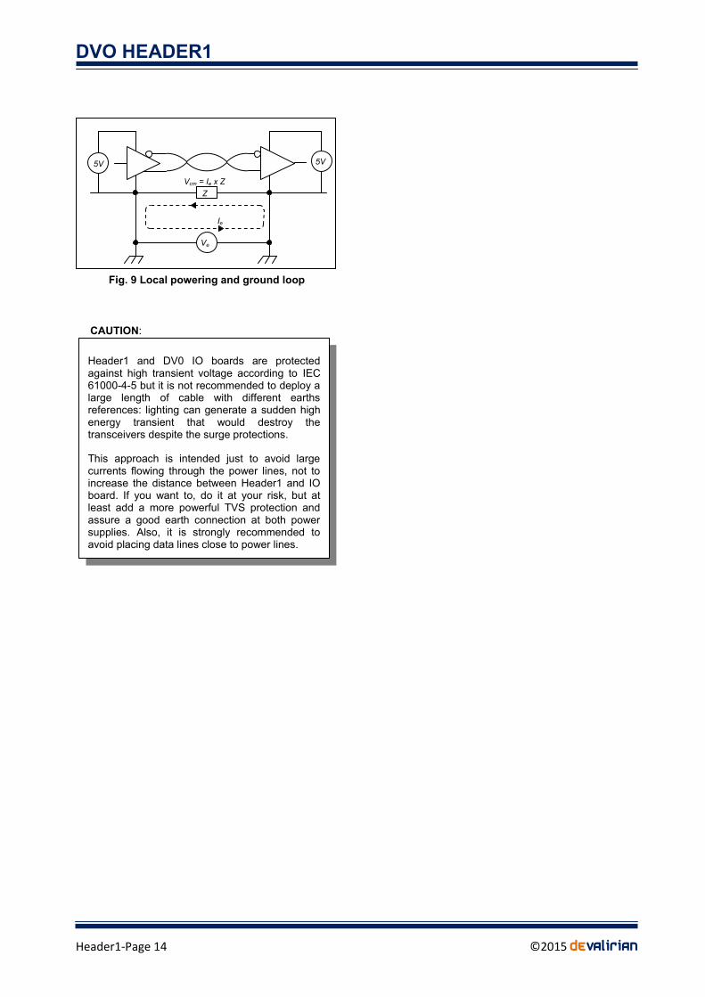
DVO HEADER1
Header1-Page 15 copy2015 deValirian
3 BATTERY DIMENSIONING
The Header1 board is intended for two battery
scenarios
Wall Mode The system is powered by a wall
adapter and the battery is dimensioned only for
assuring a clean shutdown
Battery Mode The system is mainly powered by
a wall adapter but in case of failure the system
continues its operation powered by the battery
until the voltage battery drops below a save
preconfigured value witch allows a clean
shutdown
Obviously the second scenario requires a much
powerful battery than the first one
Following in this section an explanation of how to
estimate the battery capacity will be given along with
some discussions on the most suitable types of
batteries and their nominal voltage Also it is
important to calculate the optimum value for the
charging resistor However prior of battery
calculation it is worth to comment some issues
related to battery chemistry and capacity
31 Battery considerations
In this document all references to ldquobatteryrdquo stand for
ldquorechargeable batteryrdquo For our purposes
rechargeable batteries are defined by three
parameters
Chemistry Can be Nickel based Lead based or
Lithium based
Capacity Indicates the amount of energy that the
battery can store
Internal resistance The great the internal
resistance the lower the current that can be
drown from the battery
311 Battery chemistry
Lithium base batteries requires a smart charge
system The Header1 board DOESNrsquoT HAVE A
SMART CHARGE SYSTEM so Lithium based
batteries are FORBIDEN to Header1
Nickel based batteries are nowadays only Nickel-
Metal Hydride chemistry because the ancient Nickel
Cadmium technology has become prohibited This
batteries are robust easy to charge if the current is
not great better ratio capacityweight and
capacityvolume than lead batteries but much
expensive
Lead battery are also robust and easy to charge
cheaper than Nickel batteries but they need much
volume and their weight is important
As a rule of thumb when in battery mode if there is
no restriction about volume and weight the better
decision is a lead battery More exactly we
recommend sealed lead acid because they are
maintenance-free and their price is very attractive
However during the last years NiMH batteries have
decreased their price close to the lead battery type
so it could be interesting to choice a NiMH if the
weight-volume restrictions are important Also when
in wall mode there is no need of powerful battery and
it is better to choice a little 9V PP3 NiMH model as
explained below at 32 Wall Mode example
The most important parameter related to the
chemistry is the cell voltage at full charge nominal
and end of charge The voltage per cell of both
chemistries exhibits the same type of curve as they
are discharge
Figure 10 shows the discharge curve At full charge
the cell voltage is slightly higher than the nominal
value but this level drops early as the battery
discharge begin Then there is a plateau at nominal
voltage that remains for the 90 of the discharge
cycle Finally close to the end of charge there is an
abrupt drop of voltage It is important that when the
battery reaches the end of voltage threshold the
operating systems issues a shutdown immediately
because the time for a full voltage drop is
unpredictable Also its is recommended to be
conservative with this threshold
Charge
100
0
Cell voltage
Full charge
Nominal End of charge
Fig 10 NiMH and Lead battery discharge curve
CAUTION
Some Lithium batteries have internal protection against over and under voltage but most batteries donrsquot have any kind of such protection so the risk of blowing or firing a Lithium based battery is extremely high if it is connected to the Header1 board
DVO HEADER1
Header1-Page 16 copy2015 deValirian
Table 1 shows the standard values for full charge
nominal and end of charge values per cell and per
chemistry
Commercial battery packs come with some standard
number of cells Designers have to multiply the
number of cell by the End of Charge value to obtain
the min_voltage parameter The dv0_manager
program continuously compares the battery voltage
against the min_voltage parameter and sends a
shutdown command when the battery voltage falls
below this value
Table 1 Cell voltages
Chemistry Full charge Nominal End of charge
NiMH 18V 12V 09V
Lead Acid 21V 2V 195V
Caution check these values with the manufacturer
data because there can be a significant tolerance
among models and types
The default value for min_voltage is 6V but can be
modified as a command line parameter when
launching dv0_manager
Table 2 shows the recommended values of
min_voltage for the most common packs of
commercial batteries
Table 2 min_voltage recommended values
Chemistry Nominal voltage
Number of cells
min_voltage value
Lead Acid 6V 3 Not recommended
Lead Acid 12V 6 119
Lead Acid 24V 12
NiMH 72V 6 6
NiMH 84V 7 7
NiMH 96V 8 8
NiMH 144V 12 12
NiMH 18V 15 15
312 Battery capacity
In theory battery capacity should express the
maximum amount of energy that the battery can store
but in practice it is expressed as Amperes-Hour (Ah)
which is a charge magnitude not an energy
magnitude Designers have to multiply the ldquocapacityrdquo
(Ah) by the nominal voltage battery pack (Volts) to
obtain Watts-Hour which it is an energy magnitude
However despite the formal considerations it is quite
convenient to use the battery capacity in Ampere-
Hour to estimate the battery duration For example a
battery of 4800mAh as a rule of thumb can supply a
system that requires 48A during one hour or a
system that requires 24A for two hours and so forth
Also the battery capacity is used as a relative
measure of charging or discharging current For
example if a battery of 4800mAh is discharged with a
current of 48 amperes it is said that the discharge
current is 1C if the current is 96A then the current is
2C and for a 24A the current is C2 This value will
be used for charging current calculation below at 34
Battery dimensioning examples
313 Internal resistance
The internal resistance depends on the quality of the
battery and determines its application The greater the
internal resistance the greater the voltage drop for a
given current Batteries designed to supply motors
have a very low resistance and allows discharge
current as big as 30C o more
For the purposes of this application the current
consumption involved is quite low so no issues at this
point are expected except for the little 9V battery in
the example 341
32 Wall Mode
Note Wall Mode operation is selected by leaving
connected the jumper 1 as shown in Figure 2
The Wall Mode is intended for applications where the
main power source comes from a wall adapter supply
and a battery is needed only for safe shutdown
purposes or sleeping features as time keeping
scheduled restart onoff pushbutton etc
Shutdown condition The Header1 control unit
issues a shutdown command to the Raspberry Pi
board whenever the voltage on the Wall Input is lower
than the voltage in the Battery Input for more than five
seconds When the shutdown starts the control unit
of the Header1 waits a determinate number of
seconds (shutdown_time) and cuts the power of the
Raspberry Pi and the DV0 bus It is possible and
recommended to cut the power of the DV0 bus by
setting the parameter ndashcut_vbus as a command line
parameter of dv0_manager
Energy needs The battery must supply energy to the
Raspberry Board during the shutdown process and to
the Header1 control unit to keep the real time clock
running
321 Battery capacity calculation procedure
To calculate the battery capacity designers must
follows these steps
Determine Pbattery from 232 Set PDV0 zero if
parameter ndashcut_vbus is set
Obtain Icontrol(Off) from 233
DVO HEADER1
Header1-Page 17 copy2015 deValirian
Measure the actual shutdown time and set it as a
command line parameter of dv0_manager by
setting ndashshutdown_time nn where nn is the
number of seconds of shutdown time measured
Default parameter is 30 but experiences proof
that the Raspbian distro needs only 15 seconds to
completely halt Letrsquos call it Tsd (in seconds)
Decide how many hours must the Header1 kept
the real time clock running before battery fails
Letrsquos call it Trtc (in hours)
Then for a given battery with nominal voltage Vn the
capacity C (in Amperes x Hour) required is
Note if the chargedischarge cycle is periodic it is not
recommended to dimension the battery to the exact
value found above since this means that a full
discharge state is achieve each cycle Keep in mind
that batteriersquos life is rated to rough 500 full discharge
cycles but this value increases dramatically as the
discharge level increases
322 Battery charge calculation procedure
Because there is no temperature or voltage sensor
inside the Header1 board charging battery is made
by supplying a low rate continuous current throughout
a resistor from Wall input to the battery There is a
internal resistor of 470Ω rated at 1W of power
dissipation for this purpose
Designers must calculate the theoretical value of the
charge resistor (Rchrg) and if it is close to the internal
resistor of 470Ω no more actions are needed but if
the final result is lower than 470Ω then an external
resistor must be place so that the parallel value of the
external resistor with the internal one matches the
theoretical value
These are the steps
Decide the time in hours required to full charge
the battery from a full discharged state Suitable
values are form 10 to 16 Letrsquos call it Tchrg (in
hours)
Calculate the charge current for a giving battery
capacity C (in Amperes x hour) computed as Ichrg
= CTchrg
Decide a voltage for Wall input The closer to the
battery voltage the better Letrsquos call it Vwall
Calculate Rchrg as
Rchrg = (VWALL-Vn)Ichrg
Calculate the power dissipated by this resistor as
PRchrg = Rchrg (Ichrg)2
Then compares Rchrg and PRchrg with the internal
value of 470Ω 1W It they are close enough just let
the internal resistor charge the battery and recalculate
the charging time (in hours) as
Tchrg = C (Vwall-Vn) 470
If Rchrg is quite lower than 470Ω then connect an
external resistor (Rext) to the battery charge connector
(see 21) so that
Rext = (470Rchrg)470-Rchrg)
Which is the solution of the parallel resistor equation
Maintain the rated power calculated for Rchrg
33 Battery mode
Note Battery Mode operation is selected by
leaving unconnected the jumper 1 as shown in
Figure 2
The Battery Mode is intended for applications where
the main power source is a battery and Wall Input is
used just for slow battery charging saving battery
energy or for feeding the board when the battery
needs to be temporally disconnected
The 5V power to Rasperry Pi is always obtained from
the input source that exhibits the upper voltage value
and automatic balance is made when one source falls
below the other one without affecting the stability of
Raspberry Pi power supply
Shutdown condition the shutdown command is
issued only when the Battery input voltage falls below
min_voltage for more than five seconds no matters
what voltage is at Wall input As in Wall mode it is
possible to cut the power of the DV0 bus setting the
parameter ndashcut_vbus as a command line parameter of
dv0_manager
Energy needs The battery must supply energy to the
Raspberry Board and DV0 bus during the absence of
wall input source Also if the designer plans to keep
the system in stand by and start it at scheduled time
the battery must supply energy to the Header1 control
unit to maintain the real time clock and the restart
scheduler
Maximum charge current for this method is C4 However we recommend at maximum current of C10 for completely safe operation an wide battery life
CAUTION
[Ah] C = (PbatteryTsd)3600 + Vn Icontrol(Off)Trtc
Vn
DVO HEADER1
Header1-Page 18 copy2015 deValirian
331 Battery capacity calculation procedure
To calculate the battery capacity designers must
follows these steps
Determine Pbattery from 232
Obtain Icontrol(Off) from 233
Decide how many time (in hours) must the full
system (Raspberry plus DV0 boards running) be
powered by the battery (that is no Wall input
energy) Letrsquos call it Ton
Decide how many time (in hours) must the system
be in off state (that is Raspberry and DV0 boards
off and Header1 control unit keeps running the
real time clock) powered only by the battery Letrsquos
call it Toff
Then for a given battery with nominal voltage Vn the
capacity C (in Amperes x Hour) required is
C = PbatteryTon Vn+ Icontrol(Off)Toff
332 Battery charge calculation procedure
There is no methodological difference between wall
mode and battery mode for charge calculations
purposes just follow the same steps described at
322 However it is worth to note that the power
required for the charge resistor will be much higher
that 1W so the internal resistance of the Header1 is
useless in this mode and an external resistor will be
mandatory
34 Battery dimensioning examples
The following examples cover the mainly intended use
of Header1 board
Clean shutdown to avoid SD card corruption (wall
mode)
Control and surveillance systems (battery mode)
341 Wall mode calculations example
Case the system is a panel information in a mall It is
supplied by a wall input source form 800 am to 1000
pm and has Raspberry Picopy A model with no camera
and two IO_A boards connected to the bus There is
no need to save the state of IO_A boards so ndash
cut_vbus parameter is set when invoking
dv0_manager
At 800 the power at Wall input is present and the
Header1 will start the Raspberry and the DV0 bus
boards It is required that the Header1 sets the real
time clock date (kept during all night long) to the
Raspberry operating system so ndashforce_date
parameter is set when invoking dv0_manager
Assuming that the display is powered by an external
source and using the Example 1 from 233 we know
that the power of Wall input is Pwall = 531 [W] Also
from 233 the power consumption during shutdown
time (when wall input disappears) is Pbattery(ON) = 526
- 1675 = 3575 [W] (because cut_vbus is set)
Icontrol(Off) is 00035A (from 233)
Several measuring shutdown time gives a mean time
of 12 seconds Letrsquos be conservative and set Tsd as 20
seconds so dv0_manager is called with ndash
shutdown_time 20
Battery has to survive during 1000 pm to 800 am so
Trtc is 10
A small 9V PP3 NiMH seems to be the better choice
to this scenario Only its capacity has to be calculate
to full set battery requirements
NOTE Due to the similitude to common PP3 non
rechargeable batteries witch have 9V of nominal
voltage most distributors declare PP3 NiMH as a 9V
battery but in fact they can made as seven cells of
NiMH witch yields a 84V nominal voltage or eight
cells witch yields 96V nominal voltage Let set Vn =
84V as itrsquos the most common value on the market
Then the capacity C required is
So we can choice a common PP3 84V 200mA
NiMH battery Setting C=200mAh while discharge C is
37mAh means that the level of discharge is roughly
20 This value is far from 100 so battery life
endurance is mostly improve Some manufactures
publish life estimation depending on discharge depth
percent (but some other not)
NOTE Not only C is important to specify the battery
Designers must check the internal resistance value of
the selected battery and calculate the voltage drop
during shutdown time Then knowing that the power
delivered by the battery is Pbattery(ON)= 3575W at 84V
we conclude that the current drown from the battery is
Ibat = 357584 = 0425 [A] This peak of current
multiplied by the internal battery resistor must ensure
that the voltages at Battery input is always greater
than 65V That is Rbat lt (84-65)0435 = 436 [Ω]
(PbatteryTsd)3600 + Vn Icontrol(Off)Trtc C =
C =
Vn
(357520)3600 + 84 0003510
84
C = 0037 [Ah] = 37 [mAh]
DVO HEADER1
Header1-Page 19 copy2015 deValirian
As for the charge battery the scenario assures a
charging time from 800 am to 1000 pm that is 14
hours of charging The target is to get a full charge
from a full discharge state (maybe after holydays) in
one day to assure a all night long supply Letrsquos try a
charging current ratio of C12 Required charge
current is
Ichrg = CTchrg = 0212 = 0016 [A]
For the Wall input voltage designers must ensure that
a full charge battery voltage is always lower that the
nominal Wall voltage Since the selected battery have
7 cells of NiMH and each cell can have a full charge
voltage of 18V then a Wall input greater than 7 x 18
= 12V Letrsquos try a common value of 15V as a nominal
voltage for Wall input adapter and then compute Rchrg
and PRchrg
Rchrg = (VWALL-Vn)Ichrg = (15-84)0016 = 412[Ω]
PRchrg = Rchrg (Ichrg)2 = 412 (0016)
2 = 01 [W]
Since the internal resistance is 470Ω rated to 1W it
seems that there are not heat dissipation issues and
that the calculated value is so close to the internal
value that it is worth to check the behavior of the
charge method using only the internal resistance thus
avoiding place any external resistor
If the charge resistor is just 470Ω the charge current
is Ichrg = (15-84)470 = 0014 A In terms of C ratio
that means a charge current of C14 or in other
words a full charging time of 14 hours Just the time
allowed for charging no security factor available
Designers hate not to have a security factor for their
calculus and dealing with batteries is a very good
practice to left security margins Fortunately in this
example a full charge cycle is only needed after a
vocational period and even that not all charge is
need at the end of the day because only a 20 of the
total energy is required every night
Finally the power required to wall input adapter is
obtained from the example 1 of 233 as Pwall =
531[W] and a current of Iwall = Pwall Vwall = 53115 =
0354 [A]
Software example of dv0_manager call
dv0_manager ndashcut_vbus ndashshutdown_time 20
ndashforce_date
The cabling diagram is shown at Figure
342 Battery mode calculations examples
Case 1 Night animal movement capture The system
is a Raspberry Pi model A with a infrared camera
NoIR (infrared light is supplied by other source) Each
night at 100 am the system starts and capture video
during 3 hours and it is required to last for a 7 days
No restrictions on weight or size so a 12V Lead Acid
battery type is selected
The battery must supply full energy to the Camera-
Raspberry system during 3 hours per day and must
fed the Header1 control unit 21 hours to allow starting
at 100 each day Software settings are explained
below
From 233 we obtain that the Raspberry Pi power
during on state is
Prasp = 5 x (05+02) 08 = 44 [W]
And with a PDV0 = 0 the battery power at ON state is
Fig 11 Wall mode example
84V (9V)
PP3
200mAh
15V 04A
Wall Input adapter 15V power gt 531W
current gt 0354A
Battery PP3 84V 200mA NiMH
External charge resistor none
SUMMARY OF REQUIREMENTS
DVO HEADER1
Header1-Page 20 copy2015 deValirian
Pbattery(ON) = 44 + 03 + 0170 = 49 [W]
The battery power at OFF state is from 233
Pcontrol(OFF) = Vbat x Icontrol(OFF) = 12 x 00035 = 0042 [W]
The capacity per day is
C(per day) = (Pbattery(ON) x 3 + Pcontrol(OFF) x 21) 12 [Ah]
C(per day) = (49 x 3 + 0042 x 21) 12 = 13 [Ah]
And multiplying by seven days we obtain the total
capacity
C = 13 x 7 = 91 [Ah]
Note Auto discharge issues have been ignored due
to the low period of time considered
Software
Example of dv0_manager call
dv0_manager ndashforce_date -min_voltage 118
-start_up_time 100
Note that a minimum voltage of 118 volts is set so
when the battery charge is close to the end either a
shutdown will be performed or no startup will be
launched
The parameter start_up_time tells the dv0_manager
the periodically starting minute hour or day (see
section 4313 for more details) In this example the
Header1 will start the Raspberry board every day at 1
hour and 0 minutes
At 4 orsquoclock cron process must tell to the
dv0_manager that is time to make a shutdown and go
to OFF state This is achieved either with a killall
command with the signal power
killall ndashs SIGPWR dv0_manager
or by using the utility dv0_test free supplied with
dv0_manager
dv0_test ndashpower_off
Figure 12 shows the battery connection for this case
Case 2 Unassisted meteorological station The
system is a Raspberry Pi A model with camera and
two IO boards for weather data acquisition and a 3G
USB dongle to send the acquired data and images to
a server in internet This dongle consumes 03A at 5V
from USB The station is powered from the mains
network but must withstand a lack of mains power for
at least 4 hours It is mandatory that the battery full
charge has to be recovered after 8 hours
Letrsquos suppose that there are a weight or size
requirements and choice a 72V NiMH battery
together with a Wall adapter of 12V (both are quite
common on the shelf values)
From 233 obtain the Raspberry consumption and
add the 3G dongle consumption
Prasp = 5 x (05+02+03) 08 = 625 [W]
From 233 obtain the DV0 consumption
PDVO = 5 x (0134 + 0134) 08 = 1675 [W]
From 233 and the above calculus compute the
power from the battery
Pbattery(ON) = Prasp+PDV0+Pcontrol(ON)+Pdiode(ON) =
= 625 + 1675 + 03 + 017 = 84 [W]
Then calculate the capacity C of the battery knowing
that Ton is set to 4 by the requirements
C = PbatteryTon Vn = 844 72 = 46 [Ah]
Because of full charge is required after 6 hours the
charge current must be C8 so
Ichrg = 46 8 = 0575 [A]
Witch yields a charge resistor of
Rchrg = (Vwall-Vn)Ichrg = (12-72) 0575 = 8 [Ω]
Sealed Lead
Acid
12V 91Ah
Fig 12 Battery mode example Case 1
DVO HEADER1
Header1-Page 21 copy2015 deValirian
Because the internal resistor value is 470Ω that is
much bigger that 8Ω there is no need to recalculate
the exact parallel value and we set Rext as 8Ω This
resistor should dissipate a power of
PRchrg = Rchrg (Ichrg)2 = 8 (0575)
2 = 264 [W]
So a 5W resistor is selected
The power required for the wall input adapter must
include the charge current
Pwall = Prasp+PDV0+Pcontrol+Pdiode+Pcharge
Where Pcharge is
Pcharge = Vwall (Vwall - Vbat - 02 ) Rchrg =
= 12 (12-72-02 ) 8 = 689 [W]
And the rest of terms have been calculate above so
Pwall = 626 + 1675 + 03 + 017 + 689 = 153 [W]
IWall = PWallVWall = 153 12 = 1275 [A]
Figure 12 illustrates the schematic of wiring
Software
Example of dv0_manager call
dv0_manager ndashforce_date
Note that no minimum voltage is set because the
default set of min_value is 6V witch suits perfectly to
a 72 NiMH battery
If eventually the battery falls below 6V the Header1
control unit will cleanly shutdown the Raspberry but
even at 6V there is some remained energy inside the
battery and the control unit can maintains the real
time clock for a while until the wall input returns
Then thanks to the ndashforce_date parameter the Linux
operating system will restart with a correct time and
date
12V 13A
NiMH
72V 4600mAh
8Ω 5W
Fig 13 Battery mode example Case 2
Wall Input adapter 12V power gt 153W
current gt 1275A
Battery NiMH 72V 46 Amperes hour
External charge resistor 8Ω 5W
SUMMARY OF REQUIREMENTS
The temperature that can reach a resistor working at is rated power can be as great as 90 degrees (Celsius) In general the great the power rated the great the volume of the resistor and thus the lower the temperature rising As rule of thumb selecting a rated power twice the calculate power reduce the temperature rising to 40 degrees upon the ambient
Mount this resistance in a place that natural or forced air convection ensures a good dissipation
CAUTION
DVO HEADER1
Header1-Page 22 copy2015 deValirian
4 SOFTWARE
The Header1 board comes with several free
programs API and examples of C Python Java and
Linux scripts Their goal is to configure the power
updown behavior and scheduling and to allow user
programs to gain access of the real word reading and
writing DV0 inputoutput boards
These are all the free software parts related to
Header1
The dv0_manager program the one and only one
who talks with the Header1 control unit
The dv0_test utility command program to test the
dv0_manager and to send commands and
settings to the Header1 control board Intended to
be used in Linux scripts
The DV0 API libraries in C Java and Python A
full set of functions to control the Header1 and the
DV0 inputoutput board connected to the DV0 bus
Source code examples written in C Python and
Java (Android)
All these parts and their associate documentation are
free available in the Technical Information
section of wwwdevaliriancom
41 Architecture description
Local architecture is the most common scenario and it
is shown in the Figure 14
In this case the dv0_manager program waits for a
socket connection listening to the interface ldquolocalhostrdquo
at port ldquo6900rdquo Both dv0_test program and user
applications connect to dv0_manager using the
function ldquoOpenrdquo with that interface and port (which
are the default values) The dv0_manager ldquotunnelsrdquo
commands from dv0_test and user applications to the
Header1 control unit through the Raspberry Pi serial
interface ttyAMA0 Note that all elements run inside
the Raspberry Pi
Since the socket level physical layer is transparent to
the user applications it is possible to replicate the
local architecture to a remote architecture where the
command and data traffic between dv0_manager and
DV0 API or dv0_test travel through internet Figure 15
shows this case
In this example the Raspberry is connected to
internet via an interface which IP address is
10101010 no matter if it is an Ethernet or a WiFi
connection To accept data and commands from this
interface as their come from localhost only a few
initialization changes must be performed More
exactly the dv0_manager must be called with the ndash
ip_address command line parameter
dv0_manager ndaship_address 10101010
and the ldquoOpenrdquo function of DVO API requires a string
with that IP address
Open(rdquo10101010rdquo)
Note that when using a remote connection some
security issues must be taken into account to avoid
unexpected and unwanted connection See 43 for
more information on login restrictions for a remote
access
dv0_manager
Header1
Linux
Sockets
Level
Eth0WiFi
Raspberry Pi
10101010
DVO API dv0_test
User App
Linux Sockets Level
Remote system
INTERNET
Fig 15 Remote access architecture
dv0_manager
DVO API dv0_test
Linux Sockets Level
Header1
ttyAMA0 Raspberry Pi
User App
localhost 6900
Fig 14 Local architecture
DVO HEADER1
Header1-Page 23 copy2015 deValirian
42 dv0_manager installation
Log in using ldquopirdquo login name download dv0_manager
and dv0_test from the Technical Information section
of wwwdevaliriancom and place into some directory
For instance create and use homepidv0
Allow them execution permissions with chmod
command
chmod +x
Edit the file etcrclocal (you must need root
permissions so remember to use the command sudo
when invoking your preferred Linux editor For
example
sudo nano etcrclocal
In almost all Linux distributions this file is intended to
contents the last commands that must be launched
when the operating system boot is finish
Add a line with the dv0_manager and all desired
command line parameters and FINISH THE LINE with
the ampersand character
homepidv0dv0_manager ndashforce_date amp
The inclusion of the ampersand character at the end
of the line is mandatory or the Raspberry boot
process never end If you plan to launch
dv0_manager in a separately script it could be
interesting to use its return value
421 dv0_manager return values
If there is something wrong this program returns
prematurely with the following codes
255 (-1) if there is some syntax error at the
command line
254 (-2) if the serial channel ttyAMA0 is not free
(see below)
253 (-3) if the socket library doesnrsquot open the port
6900 or whatever declared with ndashport parameter
Try another port
422 Unblocking ttyAMA0
Since dv0_manager uses the serial channel ttyAMA0
to communicate with the Header1 control board this
serial channel must be freely available no other
operating system part can share this channel with
dv0_manager Unfortunately as a reminder of ancient
times where the console was connected to a serial
channel the Raspberry Pi distros initial configuration
take control of this channel as a root console
To free this channel edit the bootcmdlinetxt file with
root permissions
sudo nano bootcmdlinetxt
and remove carefully both commands
console=ttyAMA0115200
kgdboc=ttyAMA0115200
Then edit inittab file
sudo nano etcinittab
and comment or remove lines that contain ttyAMA0
Finally restart Linux and execute the dv0_test
program
cd homepidv0
dv0_test
If every is fine the program shows the message
ldquoConnection to localhost successfulrdquo Else either
there is a problem with the command line parameters
or with the serial channel or with the socket port
To know what the problem is begin with killing the
running dv0_manager (if it still runs)
sudo killall dv0_manager
Then execute dv0_manager direct from the shell who
will tell which one of the three failure condition
explained in 421 is responsible for the malfunction
DVO HEADER1
Header1-Page 24 copy2015 deValirian
43 dv0_manager command line
parameters
This section describes the command line parameters
accepted by the dv0_manager their meaning limits
and default values The ldquodefault valuerdquo is the value
that dv0_manager uses if the corresponding
parameter is not present at the command line call
Table 3 dv0_manager parameters summary
Parameter Value Default value
-serial_port Port device devttyAMA0
-port Port 6900
-ip_address IP Address localhost
-login Login name none
-shutdown_command Command sudo shutdown ndashh now
-shutdown_time Seconds 30
-boot_time Seconds 30
-restart_time Minutes 0
-min_voltage Tenths of V 60
-cut_vbus None false
-no_push_active None true
-force_date None false
-watch_dog Seconds 0
431 Parameter -serial_port ltportgt
Port is the name of the device where the header
board is attached If the header board is the Header1
this device is devttyAMA0 but for others headers
can be an USB-Serial emulator like devttyUSB0
Default value devttyAMA0 (Raspberry Pi)
432 Parameter -port ltport numbergt
This is the TCP port number that dv0_manager listens
to accept connections from DV0 API or dv0_test It is
not usual to change the default value of 6900 but in
some cases this value could be caught by other
application
Default value 6900
Minimum value 5000
433 Parameter -ip_address ltip_addressgt
This parameter is useful only when the user
applications or the dv0_test run in other machine that
the Raspberry Pi The ltipaddressgt must be equal to
the interface IP where the connection to a local net is
made If all they run inside the same machine the IP
address is ldquolocalhostrdquo which is the default value and
so this parameter is not needed
To know what IP address is assigned to an net port
execute the command
ifconfig -a
For example the result of this command can be
eth0 Link encapEthernetHWaddr b827ebc0fb76
inet addr10002 Bcast10255255255
(helliponly two lines are shownhellip)
Then the call to dv0_manager should be
dv0_manager ndaship_address 10002
Default value localhost
434 Parameter -login ltlogin namegt
When this parameter is set all incoming connections
to dv0_manager must be opened with the giving login
name and with their corresponding password For
example if the call to dv0_manager is
dv0_manager ndashlogin pi
then the initial DV0 API function Open must be
Open(rdquolocalhostrdquo 0 rdquopirdquo rdquoraspberryrdquo)
and the dv0_test should be
dv0_test ndashlogin pi ndashpassword raspberry
Note that dv0_manager needs to gain access to the
Linux password files in order to check the validity of
the password and that means that it must be runnning
with root privileges See 461 for more information
435 Parameter -shutdown_command
ldquoltcommandgtrdquo
This is the command that the dv0_manager executes
when a power off condition becomes true Can be
null that is rdquo rdquo if no shutdown generation is desired
Default value rdquosudo shutdown ndashh nowrdquo
436 Parameter -shutdown_time ltsecondsgt
Number of seconds that the Header1 control unit
waits before cutting off the power to the Raspberry Pi
once there is a Power Off condition true
Default value 60
Maximum value 32767
437 Parameter -boot_time ltsecondsgt
Number of seconds that the Header1 control unit
waits before considering that the boot process is
finished and thus accept and check Power Off
conditions
Default value 60
Maximum value 32767
DVO HEADER1
Header1-Page 25 copy2015 deValirian
438 Parameter -restart_time ltminutesgt
This parameter defines the number of minutes that
the Header1 control unit must wait to generate a
Power On condition after a power off condition has
been execute successfully See 112 Power Off
Conditions for more explanations about their causes
Intended to generate a full hardware reset after a
watch dog condition or when a complete system
initialization is required See 45 for useful Linux
scripts examples using this parameter and the
dv0_manager
Notes
This timer begins to run AFTER the time defined
by the shutdown_time parameter
A value of zero means that the Raspberry never
will be restarted
Restarting is only allowed if the input voltage is
greater than 6V whichever Battery or Wall input is
the greater one
Once restarted the Header1 control units forgets
this value so dv0_manager must be called with
this parameter again
Default value 0 (Never)
Maximum value 32767
439 Parameter -min_voltage ltvoltagegt
Defines the threshold voltage (in tenths of volts) of the
battery voltage that generates a power off or power on
condition (if it last for a 5 seconds) The power off
level is exactly this value while the power on
condition is at 200mV over this value This hysteresis
behavior avoids noise dependence when the battery
voltages is close to min_voltage For example if the
desired threshold is 119V then
dv0_manager ndashmin_voltage 119
In this example power off condition is at 119 but
power on waits until the voltage exceeds 121V
Default value 60 (6V)
Minimum value 60 (6V)
Maximum value 240 (240V)
4310 Parameter -cut_vbus
This parameter forces the Header1 control unit to cut
the 5V power of DV0 bus as soon as a Power Off
condition becomes true without waiting for the
shutdown_time
Very useful in wall mode when a little battery is used
to assure a clean shutdown However there are
situations when the user application must set all the
inputoutput signals to a pre-defined state before
power off and then this parameter canrsquot be set
Default value false (DV0 voltage falls after the
shutdown time together with the voltage of the
Raspberry board)
4311 Parameter -no_push_active
Setting this parameter forces the Header1 control unit
to ignore the push button input signal
Default value false (Header1 control unit doesnrsquot
ignore the push button signal)
4312 Parameter -force_date
When this parameter is set dv0_manager sets the
Linux date and time kept by the Header1 control unit
every time that the system restart
Header1 control unit date and time can be set using
either the dv0_program or the API function SetDate
(see 462)
Default value false (date is not set)
4313 Parameter -start_up_time ddhhmm
Defines the periodicity at which the Header1 control
unit will power up the system in days hours and
minutes
Examples
-start_time 10 Means every hour at minute 10
-start_time 810 Means every day at 8 hours and 10
minutes
-start_time 30810 Means every month at day 3 at
day at 8 hours and 10 minutes
Note the valuersquos correctness is not check If there is
something impossible about days hours or minutes
dv0_manager will assume as 1
Default value never
4314 Parameter -watch_dog ltsecondsgt
If this parameter is set and greater than zero the user
must issue a watchdog reset periodically with a period
smaller than the number of seconds specified If not
dv0_manager will generate a Power Off sequence
Even if the dv0_manager is hanged and donrsquot issue a
proper shutdown command the Header1 control unit
will power off the Raspberry Pi (to restart
automatically after one minute set -restart_time 1)
This feature is specially for non assisted systems to
restart the Raspberry if some software dysfunction or
DVO HEADER1
Header1-Page 26 copy2015 deValirian
electromagnetic interference hangs the Linux of the
Raspberry
Default value 0 (No watch dog reset)
Maximum value 255
44 dv0_test command line parameters
The dv0_test program is intended to be a system tool
for testing board connections verifying dv0_manager
correctness and programming Linux scripts
This section describes the command line parameters
accepted by the dv0_test their meaning limits and
default values Table 4 summarizes these parameters
Table 4 dv0_manager parameters summary
Parameter Value Default value
-ip_address IP Address localhost
-port Port number 6900
-login Login name None
-password Password None
-set_date None None
-set_restart_time Minutes 0
-power_off None None
-get_manifest Address None
-watch_dog_reset None None
441 Parameter -ip_address ltip addressgt
Use this parameter when dv0_manager has been
called with this parameter as well As explained in
433 section if dv0_manager is invoked as
dv0_manager ndaship_address 10002
then to communicate with dv0_manager dv0_test
must be called as
dv0_test ndaship_address 10002
NOTE when both dv0_manager and dv0_test run in
the same machine they can use the interface
ldquolocalhostrdquo to establish the link which is the default
value for both of them In this case there is no need
to set this parameter
442 Parameter -port ltPort numbergt
This parameter must be set only if the default port
6900 is occupied by another application forcing
dv0_manager to be called with this parameter For
example
dv0_manager ndashport 11200
then
dv0_test ndashport 11200
443 Parameter -login ltlogin namegt
When dv0_manager has been called with this
parameter then all further connections to its must
supply not only the same login name but its password
For example as in the 434 section when
dv0_manager is called like
dv0_manager ndashlogin pi
then dv0_test must supply the same login and its
valid password
dv0_test ndashlogin pi ndashpassword raspberry
Note This password is not encrypted while travelling
through internet
444 Parameter -password ltpasswordgt
Used always together with -login parameter described
above
445 Parameter -set_date
This parameters forces dv0_manager to store the
Linux date and time into the Header1 control unit The
real time clock of this control unit will continue running
from this value and used for the -start_up_time
parameter and to restore it to the Linux at Power On
time (only if parameter -force_date has been set for
the dv0_manager program)
446 Parameter -set_restart_time ltminutesgt
Tells dv0_manager the number of minutes that will
take the next restart time It overrides the
dv0_manager -restart_time parameter
447 Parameter -power_off
This parameter forces dv0_manager to start a Power
Off process
448 Parameter -get_manifest ltaddressgt
The manifest is a readable text who explains the
features available from an DVO inputoutput board
The value of ltaddressgt must match with the micro-
switch selector of the board that has to be tested
For example if there is a model IO_A board
connected which micro-switch address selector is 7
then when executing
dv0_test -get_manifest 7
the response will be
DVO HEADER1
Header1-Page 27 copy2015 deValirian
Board name IO_A
PWM Outputs 3
Pulse Inputs 3
Analog Inputs 2
Digital output group number 0 has 2 outputs
Digital output group number 1 has 4 outputs
Digital input group number 0 has 3 inputs
Which are the contents of a model IO_A board
It is worth to note that if this command is successful
that means that the whole installation is correct
dvo_manager is running it is connected with the
Header1 control unit and the Header1 DV0 Bus
cabling is correct as well
449 Parameter -watch_dog_reset
When the ndashwatch_dog parameter is set for more than
0 seconds at the dv0_manager command line
someone MUST send a watch dog reset command to
the Header1 control unit If not the Raspberry Pi will
be restarted
Using dv0_test with -watch_dog_resets periodically is
one way to avoid restarting (the other way is through
the DVO API function ResetWatchDog)
See 45 for an example on how to reset the watch dog
using crontab and dv0_test
4410 Return values of dv0_test
On successful dv0_test returns 0 If not it returns
prematurely with the following return values
255 (-1) dv0_manager does not respond Check
IpAddress and Port
254 (-2) dv0_manager refuses login or password
253 (-3) DVO header board is not connected
252 (-5) Invalid board address
251 (-6) Parameter syntax error
DVO HEADER1
Header1-Page 28 copy2015 deValirian
45 Examples of dv0_manager dv0_test
and Linux scripts
This section illustrates some configuration of
dv0_manager and the corresponding calls of
dv0_test
Note In all following examples it is assumed that the
dv0_manager runs in the directory homepidv0 and
that in the etcrclocal there is the command
cd homepidv0
prior to call dv0_manager For example the simplest
installation of dv0_manager is just edit etcrclocal
and write into it
cd homepidv0
dv0_manager amp
Note that the final ampersand is always mandatory
Figure 17 shows how to fit the shutdown_time and the
boot_time (once they are measured) and how to force
the date to the system at power up Designers must
find some way to obtain the actual date and time (at
least one time) and then call dv0_test with -set_date
parameter while Figure 18 shows the same scenario
but in a remote architecture
Figure 19 shows how to power off and restart the
whole system (Raspberry board and DVO boards)
When issuing a -power_off without setting the restart
time then there is no automatic restart Restart time
can be set when calling dv0_test or when calling
dv0_manager
Figure 20 illustrates how to customize the shutdown
command so that a previous settings of the DV0
boards outputs are accomplished before issuing the
true shutdown
dv0_manager ndashforce_date -shutdown_time 20 -boot_time 30 amp
Fig 17 Local architecture with forcing date and fitted boot and shutdown time
Somewhere once the system date is well known
File etcrclocal
dv0_test -set_date
dv0_manager ndaship_address 10001 ndashforce_date -shutdown_time 20 -boot_time 30 amp
Fig 18 Remote architecture with forcing date and fitted boot and shutdown time
Somewhere once the system date is well known (the date comes from the machine where dv0_manager runs)
File etcrclocal
dv0_test ndaship_address 10001 -set_date
dv0_manager ndashforce_date -shutdown_time 20 -boot_time 30 amp
Fig 19 Several ways to power off and to restart with fitted boot and shutdown time
Just power off and power on from the pushbutton or turning off-on input power
File etcrclocal
dv0_test ndashpower_off
Forcing a restart one minute after the shutdown process finished
dv0_test ndashpower_off -set_restart_time 1
Another way to force a power off sending a SIGPWR to dv0_manager
sudo killall -s SIGPWR dv0_manager
DVO HEADER1
Header1-Page 29 copy2015 deValirian
To do that dv0_manager is set to call a script named
my_script who thanks to a user program based on
the DV0 API sets the outputs and then executes the
true shutdown
The new script ldquomy_scriptrdquo will be executed every time
that a Power Off condition becomes true
Figure 21 describes how to protect the system by a
watch dog The dv0_manager is call with the
parameter -watch_dog set to 180 seconds so
someone must reset periodically this timer by calling
dv0_test with the -wath_dog_reset The obvious
solution is to add a line in the etccrontab that call it
every minute
Finally a script for managing the return value of
dv0_test is shown in the Figure 22 This scripts begins
calling dv0_test with the -get_manifest of the board
number supplied as a first parameter of the script
Then the variable $Res holds de result of dv0_test
(ldquo$amprdquo) and compares it with all possible return values
described in 4410
dv0_manager -shutdown_command my_script amp
Fig 20 Customized shutdown
Edit my_script and save it in the same directory of dv0_manager (homepidv0)
File etcrclocal
do some DV0 API based program and then issue a Linux shutdown
sudo shutdown ndashh now
Donrsquot forget to make it executable
sudo +x my_script
dv0_manager ndashwatch_dog 180 amp
Fig 21 Watchdog reset from crontab using dv0_test
Edit etccrontab and add the following line
File etcrclocal
1 homepidv0dv0_test -watch_dog_reset
dv0_test -get_manifest $1 1gtampnull
Res=$
if [ $Res = 0 ] then
echo Board is Ok
elif [ $Res = 255 ] then
echo dv0_manager does not respond
elif [ $Res = 254 ] then
echo invalid login or password
elif [ $Res = 253 ] then
echo Header not connected
elif [ $Res = 252 ] then
echo Invalid board address
else
echo Parameter syntax error
fi
Fig 22 Script for managing dv0_test return values
DVO HEADER1
Header1-Page 30 copy2015 deValirian
46 DV0 API
The DV0 API contains a set of functions intended to manage the Header1 control unit and all DVO inputoutput
expansion board connected to the bus There are a free implementation of this API for Java C++ and Python
languages
The steps for managing the Header1 control board
programmatically are
Create an instance of the class DV0
Call the function Open
If successful call Header1 functions related
In the following sections an example of each language will
be given creating instance calling Open function and
calling related functions and more complete examples can
be found at the end of this section
Table 5 summarize the functions related to Header1 Note that only the name of the function is listed in the table
below This is because the parameters and return values are slightly different among the three implementation (Java
C++ and Python)
Table 5 Header1 related functions
Name Description
Open Initial and mandatory function to connect with dv0_manager
SetDate Set the date and time of Header1 control unit
GetDate Get the current date and time kept by the Header1 control unit
SetRestartTime Set restart time
PowerOff Starts a power off sequence
ResetWatchDog Clears the watch dog timer (if enabled)
GetHeaderInfo Obtains status and version info of the Header1 control unit
461 Creating an instance of DV0 class
Java C++ and Python are all object oriented languages and is useful to encapsulate all the accessing to the API
throughout one object All subsequent managing functions will pass through this variable Letrsquos assume that this
variable will be called dv0 For C++ or Java the creation of this variable is thoroughly
DV0 dv0 C++ or Java
And so is for Python but slightly different (actually it is not a class)
import dv0
This data sheet summarizes the features of DV0
API functions related to Header1 board It is not
intended to be a comprehensive reference
source For more information refer to the DV0
API Reference Guide for C++ Java and Python
at wwwdevaliriancom in the Technical
Information section
WARNING
DVO HEADER1
Header1-Page 31 copy2015 deValirian
462 Connecting to dv0_manager
The connection to dv0_manager is made through the function Open
Function Open generic description
int Open(IpAddress Port Login Password) Open connection with the dv0_manager Mandatory for all other members Blocking
Parameters IpAddress is the IP where dv0_manager listens to incoming connections By default is localhost that suits perfectly is this application runs in the same machine that dv0_manager does If a remote connection is desired call dv0_manager with the argument -ip_address followed by the IP address of the internet interface of your board (use ifconfig to know it) and pass this value to the current IpAddress parameter Port is the UDP port where dv0_manager listens to incoming connections By default is 6900 but DV0_manager can listen to whatever port selected by command line argument -port In this case give the same value to current Port parameter Useful only if another application had catch this port Login and Password are required if the dv0_manager daemon is called with -login ltusernamegt argument Current Login parameter must match with ltusernamegt and a valid Password must be entered
Return values Returns 0 if connection is successful DV_NOT_CONNECTION if dv0_manager does not respond Check IpAddress and Port DV_INVALID_LOGIN if dv0_manager refuses login or password
C++ Syntax
int Open(char IpAddress = NULL int Port = 0 char Login = NULL char Password = NULL)
Java Syntax
int Open(String IpAddress int Port String Login String Password)
Python Syntax
def Open(ipAddress port login password)
Example Connect to a dv0_manager running in the same Raspberry that the current program using de default port
and with no login required The dv0_manager call can be
homepidv0dv0_manager ndashforce_date
From a C++ user program then
DV0 dv0
hellip
int r = dv0Open(NULL 0 NULL NULL)
if (r == 0)
hellip
else DisplayError(r)
From a Java user program then
DV0 dv0
hellip
int r = dv0Open(rdquordquo 0 rdquordquo rdquordquo)
if (r == 0)
hellip
else DisplayError(r)
From a Python program there are no so much differences
import dv0
res = dv0Open(0)
if (res == 0)
print (Connected to dv0_manager)
else
DVO HEADER1
Header1-Page 32 copy2015 deValirian
DisplayError(res)
Example Connect to a dv0_manager running in a Raspberry connected to internet through the interface 10002
and the current program running somewhere login name lsquopirsquo required (with default password lsquoraspberryrsquo) using de
default port The dv0_manager call can be
homepidv0dv0_manager ndaship_address 10002 ndashforce_date ndashlogin pi
From a C++ and Java user program then
DV0 dv0
hellip
int r = dv0Open(rdquo10002rdquo 0 rdquopirdquo rdquoraspberryrdquo)
if (r == 0)
hellip
else DisplayError(r)
From a Python program there are no so much differences
import dv0
res = dv0Open(100020piraspberry)
if (res == 0)
print (Connected to dv0_manager)
else
DisplayError(res)
463 API functions related to Header1
Functions SetDate and GateDate manage the real time clock of Header1 control unit
Function SetDate generic description
int SetDate(int Year int Month int Day int Hour int Minute int Second) Sets this date to the real time clock embedded in the Header1 board
Parameters
Pre-condition User must pass a valid range for each parameter and a valid global date Unpredicted behavior can occurs if an invalid date is entered Valid values Year = 20002099 Month = 112 Day = 131 Hour = 023 Minute = 059 Second = 059 Return values
Returns 0 if successful DV_NOT_CONNECTED if previous Open call had failed or connection has been canceled
C++ Syntax
int SetDate(int Year int Month int Day int Hour int Minute int Second)
Java Syntax
int SetDate(int Year int Month int Day int Hour int Minute int Second)
Python Syntax
def SetDate(Year Month Day Hour Minute Second)
DVO HEADER1
Header1-Page 33 copy2015 deValirian
Function GetDate generic description
int GetDate(int Year int Month int Day int Hour int Minute int Second) Fills parameters with the current real time clock kept by the Header1 board
Parameters
Return values
Returns 0 if successful DV_NOT_CONNECTED if previous Open call had failed or connection has been canceled
C++ Syntax
int GetDate(int ampYear int ampMonth int ampDay int ampHour int ampMinute int ampSecond)
Java Syntax
int GetDate(int Date[]) whereas Date[0] = Year Date[1] = Month Date[2] = Day Date[3] = Hour Date[4] = Minute and Date[5] = Second
Python Syntax
def GetDate() Returns a 2-elements tuple containing an array Date (as in Java) and an integer (return value) return Date Result
Function SetRestartTime generic description
int SetRestartTime(int Minutes) Informs the Header1 board that the current restart time is minutes which overloads the argument -restart_time given at the invocation of dv0_manager Parameters
Number of minutes Return values
Returns 0 if successful DV_NOT_CONNECTED if previous Open call had failed or connection has been canceled
C++ Syntax
int SetRestartTime(int Minutes)
Java Syntax
int SetRestartTime(int Minutes)
Python Syntax
def SetRestartTime(Minutes)
Function PowerOff description
int PowerOff() Tells the Header1 board to initiate a shutdown process as if it was initiated by the pushbutton or power failure Parameters
Return values
DVO HEADER1
Header1-Page 34 copy2015 deValirian
Returns 0 if successful DV_NOT_CONNECTED if previous Open call had failed or connection has been canceled
C++ Syntax
int PowerOff ()
Java Syntax
int PowerOff ()
Python Syntax
def PowerOff ()
Function ResetWatchDog description
int ResetWatchDog () Tells the Header1 board to reset the watchdog timer if it was activated by the parameter -watch_dog ltsecondsgt of dv0_manager Parameters
Return values
Returns 0 if successful DV_NOT_CONNECTED if previous Open call had failed or connection has been canceled
C++ Syntax
int ResetWatchDog ()
Java Syntax
int ResetWatchDog ()
Python Syntax
def ResetWatchDog ()
Function GetHeaderInfo description
int GetHeaderInfo (Info[8]) Fills the array Info with information from the Header1 control unit Parameters
The meaning of each occurrence of the array Info is Info[0] = Header1 version number Info[1] = Voltage at Wall input (in tenths of volts) Info[2] = Voltage at Battery input (in tenths of volts) Info[3] = Number of DV0 transmission errors detected Info[4] = Number of DV0 InputOutput boards that have been detected Info[5] = Percent of Header1 control unitrsquos memory used Info[6] = Unused Info[7] = Unused
Return values
Returns 0 if successful DV_NOT_CONNECTED if previous Open call had failed or connection has been canceled
C++ Syntax
int GetHeaderInfo (unsigned char Info[8])
Java Syntax
DVO HEADER1
Header1-Page 35 copy2015 deValirian
int GetHeaderInfo (byte Info[8])
Python Syntax
def GetHeaderInfo () Returns a 2-elements tuple containing an array Info (as in C++ or java) and an integer (return value) return Date Result
464 API examples
In this section a complete example of how to manage Header1 related functions are described both in C++ and
Python languages Java example is omitted because it is so close to C++ that only adds confusion However there is
an example of how to program an Android APP with the DV0 API that is not included in this section for the benefit of
simplicity but it can be found at wwwdevaliriancom inside the Technical Information section
4641 C++ ExampleHeader1cpp
include ltiostreamgt using namespace std include DV0h char ServAddress = NULL char LoginName = NULL char Password = NULL int Port = 0 DV0 dv0 void DisplayError(int r) int DoTest(void) int SetDate() int main() int r Trying to connect r = dv0Open(ServAddress Port LoginName Password) if (r == 0) cout ltlt Connection to dv0_manager successful ltlt endl r = DoTest() if (r = 0) DisplayError(r) else DisplayError(r) return r int DoTest(void) int option r y m d h min sec Print menu cout ltlt Menu ltlt endl cout ltlt 1-SetDate 2-GetDate 3-SetRestartTime 4-PowerOff ltlt endl cout ltlt 5-ResetWatchDog 6-GetHeaderInfo ltlt endl Get user option cin gtgt option And execute switch (option) case 1 ------------------------------------------Set Date return SetDate() case 2 ------------------------------------------Get Date r = dv0GetDate(ymdhminsec) if (r == 0) cout ltlt Date is ltlt y ltltltlt m ltltltlt d
ltlt ltlt h ltltltlt min ltltltlt sec ltlt endl
DVO HEADER1
Header1-Page 36 copy2015 deValirian
return r case 3 -----------------------------------------SetRestartTime cout ltlt Restart time (minutes) ltlt endl cin gtgt min return dv0SetRestartTime(min) case 4 -----------------------------------------PowerOff return dv0PowerOff() case 5 -----------------------------------------ResetWatchDog return dv0ResetWatchDog() case 6 -----------------------------------------GetHeaderInfo unsigned char Info[8] r = dv0GetHeaderInfo(Info) if (r == 0) cout ltlt Version ltlt (int)Info[0] ltlt endl cout ltlt VIn ltlt (float)Info[1]100 ltlt endl cout ltlt VBat ltlt (float)Info[2]100 ltlt endl cout ltlt CRC err ltlt (int)Info[3] ltlt endl cout ltlt Boards ltlt (int)Info[4] ltlt endl cout ltlt Mem ltlt (int)Info[5] ltlt endl return r cout ltlt Invalid option ltlt endl return 0 int SetDate() This function gets the current system time and sends it to the Header1 control unit time_t t = time(NULL) struct tm tm = localtime(ampt) return dv0SetDate(tmtm_year+1900tmtm_mon+1
tmtm_mdaytmtm_hourtmtm_mintmtm_sec) void DisplayError(int error) switch (error) case DV_NOT_CONNECTION
cout ltlt dv0_manager does not respond Check IpAddress and Port ltlt endl break
case DV_INVALID_LOGIN cout ltlt dv0_manager refuses login or password ltlt endl break
case DV_NOT_CONNECTED cout ltlt DVO header board is not connected ltlt endl break
case DV_INVALID_BOARD cout ltlt Invalid board address ltlt endl break
case DV_NOT_SUPPORTED cout ltlt Invalid peripheral ltlt endl break
default cout ltlt Unexpected error code ltlt endl break
DVO HEADER1
Header1-Page 37 copy2015 deValirian
4642 Python ExampleHeader1py
import sys
import dv0
def DisplayError(error)
if error == 0
return
if error == dv0DV_NOT_CONNECTION
print (dv0_manager does not respond Check IpAddress and Port)
elif error == dv0DV_INVALID_LOGIN
print (dv0_manager refuses login or password)
elif error == dv0DV_NOT_CONNECTED
print (DVO header board is not connected)
elif error == dv0DV_INVALID_BOARD
print (Invalid board address)
elif error == dv0DV_NOT_SUPPORTED
print (Invalid peripheral)
else
print (Unexpected error code error)
Assuming that the Raspberry is not this computer and connected as 10002
Also dv0_manager is called like dv0_manager -ip_address 10002 -login pi
res = dv0Open(10002 0 pi raspberry)
Assuming that the Raspberry is this computer
and dv0_manager is called just like dv0_manager
res = dv0Open(0)
looping = True
if (res == 0)
print (Connected to dv0_manager)
else
DisplayError(res)
looping = False
while looping
print (1-SetDate 2-GetDate 3-SetRestartTime 4-PowerOff)
print (5-ResetWatchDog 6-GetHeaderInfo)
option = int(input(Enter option))
if option == 1
------------------------------------------- Set Date example
year = int(input (Enter year ))
month = int(input (Enter month))
day = int(input (Enter day ))
hour = int(input (Enter hour ))
minute = int(input (Enter minute ))
second = int(input (Enter second ))
res = dv0SetDate(year month day hour minute second)
DisplayError(res)
elif option == 2
------------------------------------------- Get Date example
Dateres = dv0GetDate()
if res == 0
print(Year Date[0] Month Date[1] Day Date[2]
Hour Date[3] Minute Date[4] Second Date[5])
else
DisplayError(res)
elif option == 3
------------------------------------------- Set restart time example
DVO HEADER1
Header1-Page 38 copy2015 deValirian
minutes = int(input (Enter restart time in minutes))
res = dv0SetRestartTime(minutes)
DisplayError(res)
elif option == 4
------------------------------------------- Power Off example
res = dv0PowerOff()
DisplayError(res)
elif option == 5
------------------------------------------- Reset Watch Dog example
res = dv0ResetWatchDog()
DisplayError(res)
elif option == 6
------------------------------------------- Get Header1 or HeaderUSB example
Info res = dv0GetHeaderInfo()
if (res == dv0DV0_OK)
print (Version d Info[0])
print (VIn d Info[1]10)
print (VBat d Info[2]10)
print (CRC err d Info[3])
print (Boards d Info[4])
print (Mem d Info[5])
else
DisplayError(res)
DVO HEADER1
Header1-Page 39 copy2015 deValirian
5 MECHANICAL DRAWINGS
Hole dimensions (top view) Board dimensions (top view)
Connector dimensions (front view)
Connector dimensions (left view)
DVO HEADER1
Header1-Page 40 copy2015 deValirian
6 ACCESSORIES
The Header1 control board comes with the following accessories
One DV0 socket Model 20020004-D041B01LF
Two Spaces (M3 12mm) Model SP1112
Four bakelite washers Model AB14
Two M3 x 6mm screw Model M3X6EE
Two M3 nut Model TRM3
The spacers washers nuts and screws are intended to assembly the Header1 control board to the Rapberry Pi
board as shown in the following picture
DVO HEADER1
Header1-Page 41 copy2015 deValirian
IMPORTANT NOTICE
Information contained in this publication regarding device applications and the like is provided only for your convenience and may
be superseded by updates It is your responsibility to ensure that your application meets with your specifications
deValirian MAKES NO REPRESENTATIONS OR WARRANTIES OF ANY KIND WHETHER EXPRESS OR IMPLIED WRITTEN
OR ORAL STATUTORY OR OTHERWISE RELATED TO THE INFORMATION INCLUDING BUT NOT LIMITED TO ITS
CONDITION QUALITY PERFORMANCE MERCHANTABILITY OR FITNESS FOR PURPOSE
deValirian disclaims all liability arising from this information and its use Use of deValirian devices in life support andor safety
applications is entirely at the buyerrsquos risk and the buyer agrees to defend indemnify and hold harmless deValirian from any and all
damages claims suits or expenses resulting from such use No licenses are conveyed implicitly or otherwise under any
deValirian intellectual property rights
Header1 board is not designed to be radiation tolerant
Please be sure to implement in your equipment using the safety measures to guard against the possibility of physical injury file or
any other damaged cause in event of the failure of Header1 board deValirian shall bear no responsibility whatsoever for yoursquore your
use of Header1 board outside the prescribed scope or not in accordance with this manual
Reproduction of significant portions of deValirian information in deValirian data books or data sheets is permissible only if
reproduction is without alteration and is accompanied by all associated warranties conditions limitations and notices deValirian is
not responsible or liable for such altered documentation Information of third parties may be subject to additional restrictions
Web Site wwwdevaliriancom
Mail info infodevaliriancom
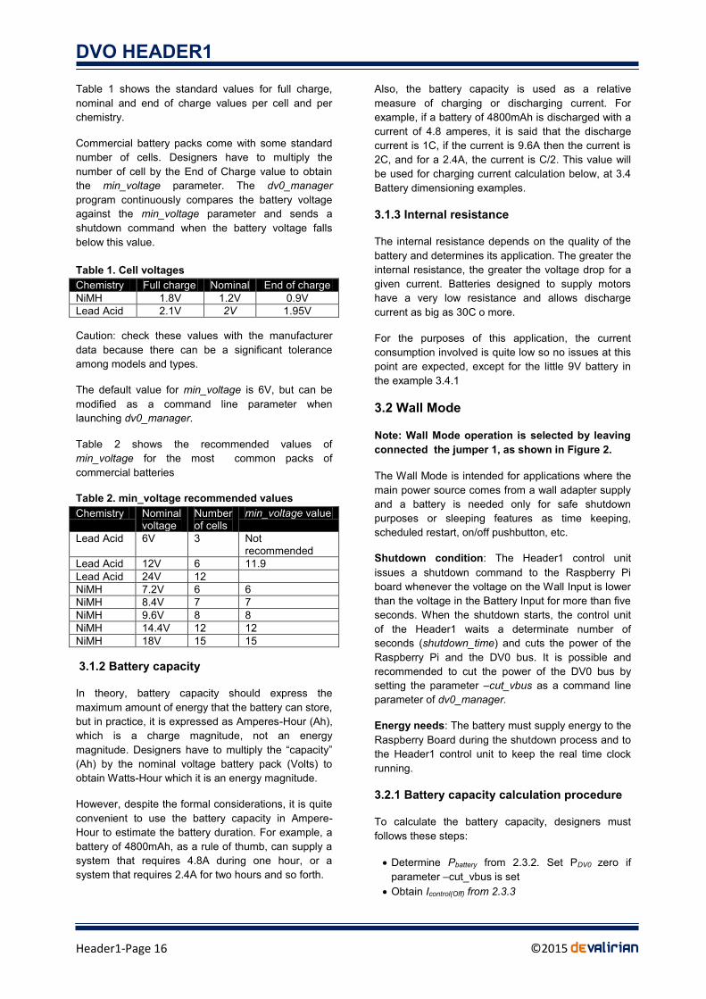
DVO HEADER1
Header1-Page 33 copy2015 deValirian
Function GetDate generic description
int GetDate(int Year int Month int Day int Hour int Minute int Second) Fills parameters with the current real time clock kept by the Header1 board
Parameters
Return values
Returns 0 if successful DV_NOT_CONNECTED if previous Open call had failed or connection has been canceled
C++ Syntax
int GetDate(int ampYear int ampMonth int ampDay int ampHour int ampMinute int ampSecond)
Java Syntax
int GetDate(int Date[]) whereas Date[0] = Year Date[1] = Month Date[2] = Day Date[3] = Hour Date[4] = Minute and Date[5] = Second
Python Syntax
def GetDate() Returns a 2-elements tuple containing an array Date (as in Java) and an integer (return value) return Date Result
Function SetRestartTime generic description
int SetRestartTime(int Minutes) Informs the Header1 board that the current restart time is minutes which overloads the argument -restart_time given at the invocation of dv0_manager Parameters
Number of minutes Return values
Returns 0 if successful DV_NOT_CONNECTED if previous Open call had failed or connection has been canceled
C++ Syntax
int SetRestartTime(int Minutes)
Java Syntax
int SetRestartTime(int Minutes)
Python Syntax
def SetRestartTime(Minutes)
Function PowerOff description
int PowerOff() Tells the Header1 board to initiate a shutdown process as if it was initiated by the pushbutton or power failure Parameters
Return values
DVO HEADER1
Header1-Page 34 copy2015 deValirian
Returns 0 if successful DV_NOT_CONNECTED if previous Open call had failed or connection has been canceled
C++ Syntax
int PowerOff ()
Java Syntax
int PowerOff ()
Python Syntax
def PowerOff ()
Function ResetWatchDog description
int ResetWatchDog () Tells the Header1 board to reset the watchdog timer if it was activated by the parameter -watch_dog ltsecondsgt of dv0_manager Parameters
Return values
Returns 0 if successful DV_NOT_CONNECTED if previous Open call had failed or connection has been canceled
C++ Syntax
int ResetWatchDog ()
Java Syntax
int ResetWatchDog ()
Python Syntax
def ResetWatchDog ()
Function GetHeaderInfo description
int GetHeaderInfo (Info[8]) Fills the array Info with information from the Header1 control unit Parameters
The meaning of each occurrence of the array Info is Info[0] = Header1 version number Info[1] = Voltage at Wall input (in tenths of volts) Info[2] = Voltage at Battery input (in tenths of volts) Info[3] = Number of DV0 transmission errors detected Info[4] = Number of DV0 InputOutput boards that have been detected Info[5] = Percent of Header1 control unitrsquos memory used Info[6] = Unused Info[7] = Unused
Return values
Returns 0 if successful DV_NOT_CONNECTED if previous Open call had failed or connection has been canceled
C++ Syntax
int GetHeaderInfo (unsigned char Info[8])
Java Syntax
DVO HEADER1
Header1-Page 35 copy2015 deValirian
int GetHeaderInfo (byte Info[8])
Python Syntax
def GetHeaderInfo () Returns a 2-elements tuple containing an array Info (as in C++ or java) and an integer (return value) return Date Result
464 API examples
In this section a complete example of how to manage Header1 related functions are described both in C++ and
Python languages Java example is omitted because it is so close to C++ that only adds confusion However there is
an example of how to program an Android APP with the DV0 API that is not included in this section for the benefit of
simplicity but it can be found at wwwdevaliriancom inside the Technical Information section
4641 C++ ExampleHeader1cpp
include ltiostreamgt using namespace std include DV0h char ServAddress = NULL char LoginName = NULL char Password = NULL int Port = 0 DV0 dv0 void DisplayError(int r) int DoTest(void) int SetDate() int main() int r Trying to connect r = dv0Open(ServAddress Port LoginName Password) if (r == 0) cout ltlt Connection to dv0_manager successful ltlt endl r = DoTest() if (r = 0) DisplayError(r) else DisplayError(r) return r int DoTest(void) int option r y m d h min sec Print menu cout ltlt Menu ltlt endl cout ltlt 1-SetDate 2-GetDate 3-SetRestartTime 4-PowerOff ltlt endl cout ltlt 5-ResetWatchDog 6-GetHeaderInfo ltlt endl Get user option cin gtgt option And execute switch (option) case 1 ------------------------------------------Set Date return SetDate() case 2 ------------------------------------------Get Date r = dv0GetDate(ymdhminsec) if (r == 0) cout ltlt Date is ltlt y ltltltlt m ltltltlt d
ltlt ltlt h ltltltlt min ltltltlt sec ltlt endl
DVO HEADER1
Header1-Page 36 copy2015 deValirian
return r case 3 -----------------------------------------SetRestartTime cout ltlt Restart time (minutes) ltlt endl cin gtgt min return dv0SetRestartTime(min) case 4 -----------------------------------------PowerOff return dv0PowerOff() case 5 -----------------------------------------ResetWatchDog return dv0ResetWatchDog() case 6 -----------------------------------------GetHeaderInfo unsigned char Info[8] r = dv0GetHeaderInfo(Info) if (r == 0) cout ltlt Version ltlt (int)Info[0] ltlt endl cout ltlt VIn ltlt (float)Info[1]100 ltlt endl cout ltlt VBat ltlt (float)Info[2]100 ltlt endl cout ltlt CRC err ltlt (int)Info[3] ltlt endl cout ltlt Boards ltlt (int)Info[4] ltlt endl cout ltlt Mem ltlt (int)Info[5] ltlt endl return r cout ltlt Invalid option ltlt endl return 0 int SetDate() This function gets the current system time and sends it to the Header1 control unit time_t t = time(NULL) struct tm tm = localtime(ampt) return dv0SetDate(tmtm_year+1900tmtm_mon+1
tmtm_mdaytmtm_hourtmtm_mintmtm_sec) void DisplayError(int error) switch (error) case DV_NOT_CONNECTION
cout ltlt dv0_manager does not respond Check IpAddress and Port ltlt endl break
case DV_INVALID_LOGIN cout ltlt dv0_manager refuses login or password ltlt endl break
case DV_NOT_CONNECTED cout ltlt DVO header board is not connected ltlt endl break
case DV_INVALID_BOARD cout ltlt Invalid board address ltlt endl break
case DV_NOT_SUPPORTED cout ltlt Invalid peripheral ltlt endl break
default cout ltlt Unexpected error code ltlt endl break
DVO HEADER1
Header1-Page 37 copy2015 deValirian
4642 Python ExampleHeader1py
import sys
import dv0
def DisplayError(error)
if error == 0
return
if error == dv0DV_NOT_CONNECTION
print (dv0_manager does not respond Check IpAddress and Port)
elif error == dv0DV_INVALID_LOGIN
print (dv0_manager refuses login or password)
elif error == dv0DV_NOT_CONNECTED
print (DVO header board is not connected)
elif error == dv0DV_INVALID_BOARD
print (Invalid board address)
elif error == dv0DV_NOT_SUPPORTED
print (Invalid peripheral)
else
print (Unexpected error code error)
Assuming that the Raspberry is not this computer and connected as 10002
Also dv0_manager is called like dv0_manager -ip_address 10002 -login pi
res = dv0Open(10002 0 pi raspberry)
Assuming that the Raspberry is this computer
and dv0_manager is called just like dv0_manager
res = dv0Open(0)
looping = True
if (res == 0)
print (Connected to dv0_manager)
else
DisplayError(res)
looping = False
while looping
print (1-SetDate 2-GetDate 3-SetRestartTime 4-PowerOff)
print (5-ResetWatchDog 6-GetHeaderInfo)
option = int(input(Enter option))
if option == 1
------------------------------------------- Set Date example
year = int(input (Enter year ))
month = int(input (Enter month))
day = int(input (Enter day ))
hour = int(input (Enter hour ))
minute = int(input (Enter minute ))
second = int(input (Enter second ))
res = dv0SetDate(year month day hour minute second)
DisplayError(res)
elif option == 2
------------------------------------------- Get Date example
Dateres = dv0GetDate()
if res == 0
print(Year Date[0] Month Date[1] Day Date[2]
Hour Date[3] Minute Date[4] Second Date[5])
else
DisplayError(res)
elif option == 3
------------------------------------------- Set restart time example
DVO HEADER1
Header1-Page 38 copy2015 deValirian
minutes = int(input (Enter restart time in minutes))
res = dv0SetRestartTime(minutes)
DisplayError(res)
elif option == 4
------------------------------------------- Power Off example
res = dv0PowerOff()
DisplayError(res)
elif option == 5
------------------------------------------- Reset Watch Dog example
res = dv0ResetWatchDog()
DisplayError(res)
elif option == 6
------------------------------------------- Get Header1 or HeaderUSB example
Info res = dv0GetHeaderInfo()
if (res == dv0DV0_OK)
print (Version d Info[0])
print (VIn d Info[1]10)
print (VBat d Info[2]10)
print (CRC err d Info[3])
print (Boards d Info[4])
print (Mem d Info[5])
else
DisplayError(res)
DVO HEADER1
Header1-Page 39 copy2015 deValirian
5 MECHANICAL DRAWINGS
Hole dimensions (top view) Board dimensions (top view)
Connector dimensions (front view)
Connector dimensions (left view)
DVO HEADER1
Header1-Page 40 copy2015 deValirian
6 ACCESSORIES
The Header1 control board comes with the following accessories
One DV0 socket Model 20020004-D041B01LF
Two Spaces (M3 12mm) Model SP1112
Four bakelite washers Model AB14
Two M3 x 6mm screw Model M3X6EE
Two M3 nut Model TRM3
The spacers washers nuts and screws are intended to assembly the Header1 control board to the Rapberry Pi
board as shown in the following picture
DVO HEADER1
Header1-Page 41 copy2015 deValirian
IMPORTANT NOTICE
Information contained in this publication regarding device applications and the like is provided only for your convenience and may
be superseded by updates It is your responsibility to ensure that your application meets with your specifications
deValirian MAKES NO REPRESENTATIONS OR WARRANTIES OF ANY KIND WHETHER EXPRESS OR IMPLIED WRITTEN
OR ORAL STATUTORY OR OTHERWISE RELATED TO THE INFORMATION INCLUDING BUT NOT LIMITED TO ITS
CONDITION QUALITY PERFORMANCE MERCHANTABILITY OR FITNESS FOR PURPOSE
deValirian disclaims all liability arising from this information and its use Use of deValirian devices in life support andor safety
applications is entirely at the buyerrsquos risk and the buyer agrees to defend indemnify and hold harmless deValirian from any and all
damages claims suits or expenses resulting from such use No licenses are conveyed implicitly or otherwise under any
deValirian intellectual property rights
Header1 board is not designed to be radiation tolerant
Please be sure to implement in your equipment using the safety measures to guard against the possibility of physical injury file or
any other damaged cause in event of the failure of Header1 board deValirian shall bear no responsibility whatsoever for yoursquore your
use of Header1 board outside the prescribed scope or not in accordance with this manual
Reproduction of significant portions of deValirian information in deValirian data books or data sheets is permissible only if
reproduction is without alteration and is accompanied by all associated warranties conditions limitations and notices deValirian is
not responsible or liable for such altered documentation Information of third parties may be subject to additional restrictions
Web Site wwwdevaliriancom
Mail info infodevaliriancom
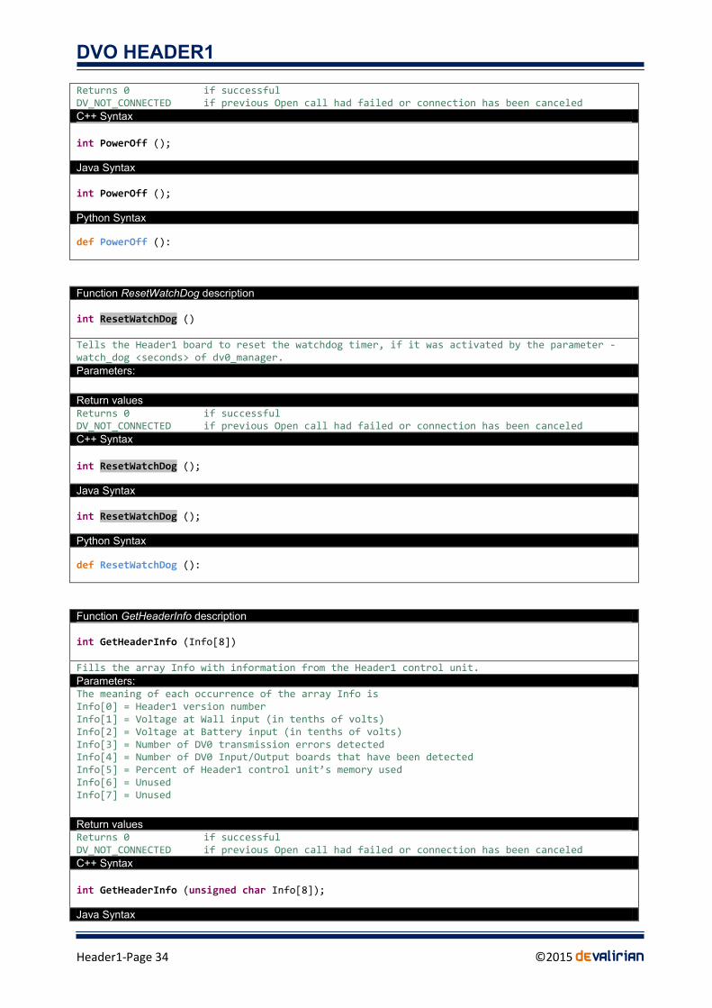
DVO HEADER1
Header1-Page 41 copy2015 deValirian
IMPORTANT NOTICE
Information contained in this publication regarding device applications and the like is provided only for your convenience and may
be superseded by updates It is your responsibility to ensure that your application meets with your specifications
deValirian MAKES NO REPRESENTATIONS OR WARRANTIES OF ANY KIND WHETHER EXPRESS OR IMPLIED WRITTEN
OR ORAL STATUTORY OR OTHERWISE RELATED TO THE INFORMATION INCLUDING BUT NOT LIMITED TO ITS
CONDITION QUALITY PERFORMANCE MERCHANTABILITY OR FITNESS FOR PURPOSE
deValirian disclaims all liability arising from this information and its use Use of deValirian devices in life support andor safety
applications is entirely at the buyerrsquos risk and the buyer agrees to defend indemnify and hold harmless deValirian from any and all
damages claims suits or expenses resulting from such use No licenses are conveyed implicitly or otherwise under any
deValirian intellectual property rights
Header1 board is not designed to be radiation tolerant
Please be sure to implement in your equipment using the safety measures to guard against the possibility of physical injury file or
any other damaged cause in event of the failure of Header1 board deValirian shall bear no responsibility whatsoever for yoursquore your
use of Header1 board outside the prescribed scope or not in accordance with this manual
Reproduction of significant portions of deValirian information in deValirian data books or data sheets is permissible only if
reproduction is without alteration and is accompanied by all associated warranties conditions limitations and notices deValirian is
not responsible or liable for such altered documentation Information of third parties may be subject to additional restrictions
Web Site wwwdevaliriancom
Mail info infodevaliriancom