Embed Size (px)
Citation preview

DEVELOPING AN AEROELASTIC STABILITY ANALYSIS PROCESS FOR LARGE WIND TURBINES USING MULTIBODY SIMULATION
A. Rezaeian, S. Hauptmann, MesH Engineering GmbH, Division Wind Energy Wankelstraße 3, 70563 Stuttgart, Germany
[email protected] [email protected]
Keywords: Time Periodic System, Floquet Theory, Multiblade Coordinate Transformation, Aeroelastic Stability, Linear System Identification
Abstract
Design of large wind turbines, especially an innovative one, needs to be verified and approved and eventually modified to have safe aeroelastic stability margins at its operating and parked (idling) conditions. In general, for a large wind turbine depending on its design and operating conditions, different types of instabilities can occur [1], [2], [3]. Rotor blade flutter, stall-induced vibration, whirl flutter [4], aeromechanical instability and hydro-aeroelastic instability (for offshore wind turbines) [3] are some of the known instabilities. Instabilities can lead to a destructive failure or limit-cycle oscillation (e.g. by stall flutter) causing structural fatigue. Therefore, it is very important to verify in design stage of a large wind turbine all possible instabilities and prevent them to occur with design change. Aeroelastic stability analysis of a system requires in general:
a. Structural model, specifying the static and dynamic characteristic (e.g. eigenfrequencies) of the real system
b. Aerodynamic model with sufficient accuracy, depending on the type of the considered aeroelastic instability
c. Method and procedure to perform the stability analysis with the data from a and b
For modelling the structure of onshore and offshore wind turbines, multibody simulation has already shown its advantages for generating detailed wind turbine models to the wind energy industry and so far has been used by many engineers. However, stability analysis of wind turbines as time periodic systems using multibody simulation needs in most cases additional tool and new code development. In this work, SIMPACK [5] are used as multibody simulation tool for modelling the wind turbine structure. Aerodynamic loads are calculated with AeroDyn [6] using SIMPACK-AeroDyn coupling [7]. To be able to do parametric aeroelastic or hydro-aeroelastic stability analysis in design stage, based on the data provided by multibody simulation (e.g. discrete-time state space matrices), different stability analysis approaches (e.g. stability analysis using Floquet theory and multiblade coordinate transformation) have been defined and written as MATLAB programs and will be implemented in a stability analysis tool. Figure 1 shows schematically all the defined stability analysis approaches.
! Figure 1: Stability analysis of wind turbines, different approaches
• Stability analysis based on Floquet theory A MATLAB script uses linear system matrices ([A]) of a time periodic system, generated by the
multibody simulation tool and at the different instants of time inside a time period, and applies the Fourier interpolation approach to determine the linear system matrix at any arbitrary time ([A(t+T)]). Using this, next part of the script calculates the Floquet transition matrix and the eigenvalues (characteristic multipliers) of this matrix. The last part of the script determines based on the absolute value of the characteristic multipliers, whether the simulated system is stable or not and plots the characteristic multipliers and exponents.
• Stability analysis using multiblade coordinate transformation (MBT) In this approach like the previous one, linear system matrices of a time periodic system, generated at different instants of time inside a time period, are used by a MATLAB script and transformed into the multiblade coordinate. This transformation might change the system matrix from periodic to a time invariant one. If not, an azimuthal averaged determination of the transformed linear system matrices leads to have an estimated time invariant system matrix. Eigenvalue analysis of this matrix is then used for the stability prediction.
• Stability analysis using data from time Simulation The idea here is, whether to perform the stability analysis directly by response analysis in time domain or using the model states data from time simulation to determine the elements of the linear time periodic system matrix (linear system identification) or to determine the Floquet transition matrix using the data from time simulation. For the stability analysis, after determination of linear time periodic system matrix from time data, one of the first or second approaches can be used.
To verify the above described stability analysis approaches, a generic three-bladed rotor with zero structural damping has been simulated in SIMPACK and used as a process verification model. Figure 2 shows this rotor model.
! Figure 2: Generic three-bladed rotor for verification of stability analysis approaches
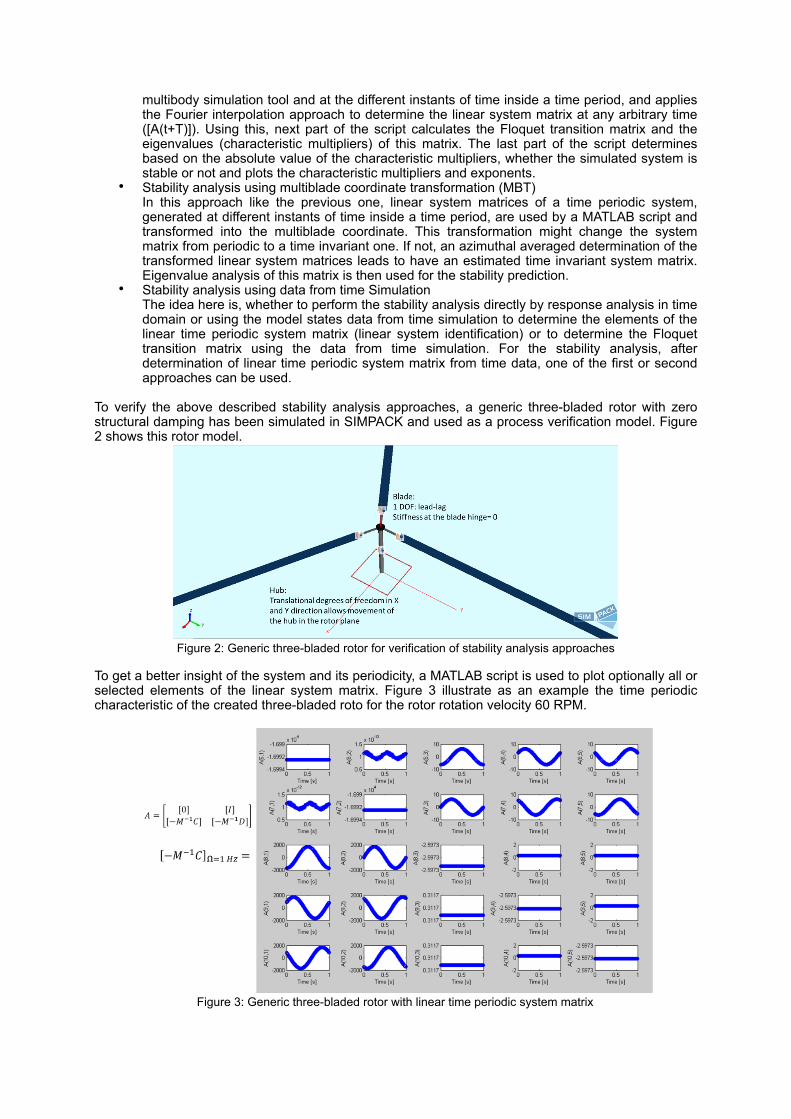
To get a better insight of the system and its periodicity, a MATLAB script is used to plot optionally all or selected elements of the linear system matrix. Figure 3 illustrate as an example the time periodic characteristic of the created three-bladed roto for the rotor rotation velocity 60 RPM.
! Figure 3: Generic three-bladed rotor with linear time periodic system matrix
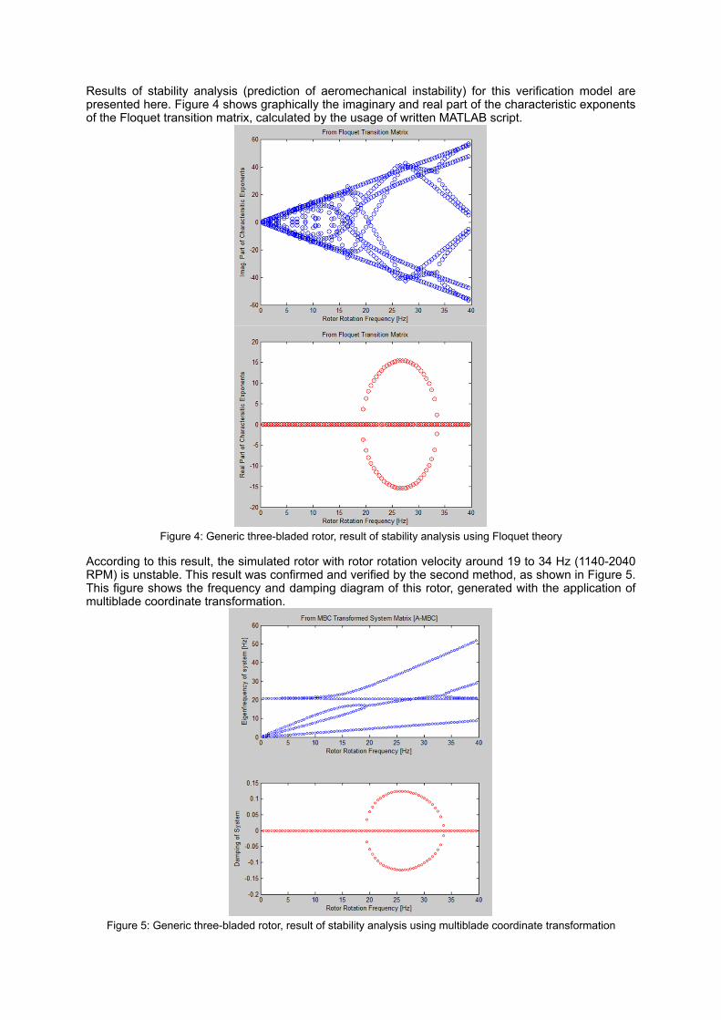
Results of stability analysis (prediction of aeromechanical instability) for this verification model are presented here. Figure 4 shows graphically the imaginary and real part of the characteristic exponents of the Floquet transition matrix, calculated by the usage of written MATLAB script.
! Figure 4: Generic three-bladed rotor, result of stability analysis using Floquet theory
According to this result, the simulated rotor with rotor rotation velocity around 19 to 34 Hz (1140-2040 RPM) is unstable. This result was confirmed and verified by the second method, as shown in Figure 5. This figure shows the frequency and damping diagram of this rotor, generated with the application of multiblade coordinate transformation.
! Figure 5: Generic three-bladed rotor, result of stability analysis using multiblade coordinate transformation
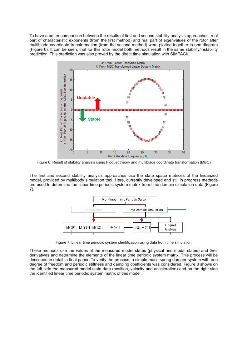
To have a better comparison between the results of first and second stability analysis approaches, real part of characteristic exponents (from the first method) and real part of eigenvalues of the rotor after multiblade coordinate transformation (from the second method) were plotted together in one diagram (Figure 6). It can be seen, that for this rotor model both methods result in the same stability/instability prediction. This prediction was also proved by the direct time simulation with SIMPACK.
! Figure 6: Result of stability analysis using Floquet theory and multiblade coordinate transformation (MBC)
The first and second stability analysis approaches use the state space matrices of the linearized model, provided by multibody simulation tool. Here, currently developed and still in progress methods are used to determine the linear time periodic system matrix from time domain simulation data (Figure 7).
!
Figure 7: Linear time periodic system identification using data from time simulation
These methods use the values of the measured model states (physical and modal states) and their derivatives and determine the elements of the linear time periodic system matrix. This process will be described in detail in final paper. To verify the process, a simple mass spring damper system with one degree of freedom and periodic stiffness and damping coefficients was considered. Figure 8 shows on the left side the measured model state data (position, velocity and acceleration) and on the right side the identified linear time periodic system matrix of this model.
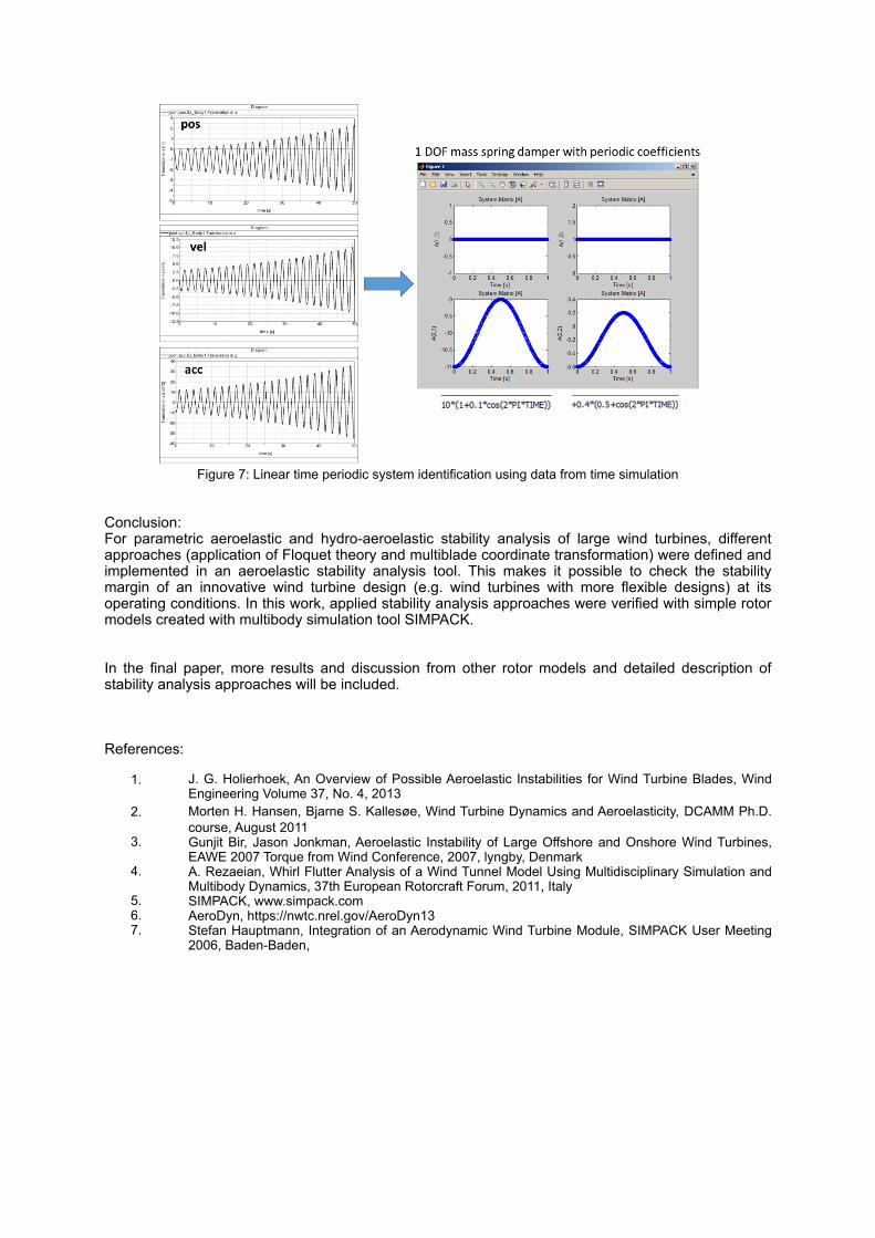
! Figure 7: Linear time periodic system identification using data from time simulation
Conclusion: For parametric aeroelastic and hydro-aeroelastic stability analysis of large wind turbines, different approaches (application of Floquet theory and multiblade coordinate transformation) were defined and implemented in an aeroelastic stability analysis tool. This makes it possible to check the stability margin of an innovative wind turbine design (e.g. wind turbines with more flexible designs) at its operating conditions. In this work, applied stability analysis approaches were verified with simple rotor models created with multibody simulation tool SIMPACK.
In the final paper, more results and discussion from other rotor models and detailed description of stability analysis approaches will be included.
References:
1. J. G. Holierhoek, An Overview of Possible Aeroelastic Instabilities for Wind Turbine Blades, Wind Engineering Volume 37, No. 4, 2013
2. Morten H. Hansen, Bjarne S. Kallesøe, Wind Turbine Dynamics and Aeroelasticity, DCAMM Ph.D. course, August 2011
3. Gunjit Bir, Jason Jonkman, Aeroelastic Instability of Large Offshore and Onshore Wind Turbines, EAWE 2007 Torque from Wind Conference, 2007, lyngby, Denmark
4. A. Rezaeian, Whirl Flutter Analysis of a Wind Tunnel Model Using Multidisciplinary Simulation and Multibody Dynamics, 37th European Rotorcraft Forum, 2011, Italy
5. SIMPACK, www.simpack.com 6. AeroDyn, https://nwtc.nrel.gov/AeroDyn13 7. Stefan Hauptmann, Integration of an Aerodynamic Wind Turbine Module, SIMPACK User Meeting
2006, Baden-Baden,