Embed Size (px)
Citation preview

Departament d’Enginyeria Elèctrica
DEVELOPING AN INTERFACE FOR
WEIGHING SENSOR
AUTHOR: Pol Barnaus Fernàndez
MENTOR: Prof. Doc.-Ing. Swen Schmeiβer and Josep Font Teixidor
UNIVERSITY: Hochschule Mittweida
PERIOD: 12 March 2014 to 29 October 2014
NUMBER OF HOURS WORKED: 300h

Departament d’Enginyeria Elèctrica
Developing an interface for weighing sensor Barnaus Fernàndez, Pol 1
Abstrac
The main objective of this project is to develop an interface for a weighing sensor
SIEMENS SIWAREX R (load Cell), attached with SIWAREX U weighing module rack
for Siemens S7-300 PLC. At first, to learn more how the software works, learning
modules were controlled, like 7-segment display, site traffic light, step control and PID
controller. Finally for the weighing interface, the PLC was programmed with the software
SIMATIC MANAGER 7 and the touch panel interface was created using the software
SIMATIC WinCC flexible 2008.
Departament d’Enginyeria Elèctrica
Developing an interface for weighing sensor Barnaus Fernàndez, Pol 2
INDEX 1. OBJECTIVES ............................................................................................................... 4
2. KEYBORDS ................................................................................................................. 4
3. INTRODUCCION ........................................................................................................ 4
4. DIFERENTS ELEMENTS ........................................................................................... 5
4.1 ELEMENTS FOR WEIGHING PROCESS .............................................................. 5
4.2 PLC ........................................................................................................................... 6
4.2.1 WHAT IS THE FUNCTION OF PLC .............................................................. 7
4.2.2 APLICATIONS OF PLC TECHNOLOGY .................................................... 15
4.2.3 ADVANTAGES .............................................................................................. 18
4.2.4 DISADVANTAGES ....................................................................................... 18
4.3 SIWAREX U ........................................................................................................... 19
4.3.1 DESIGN .......................................................................................................... 19
4.3.2 FUNCTION ..................................................................................................... 20
4.3.3 ADVANTAGES .............................................................................................. 22
4.3.4 SYSTEM INTEGRATION IN SIMATIC S7 ................................................. 22
4.4 SIMATIC S7 ........................................................................................................... 23
4.4.1 DESCRIPTION ............................................................................................... 23
4.4.2 ADVANTATGES ........................................................................................... 23
4.5 SIWAREX R ........................................................................................................... 24
4.6 SIMANTIC PANEL TOUCH ................................................................................. 25
4.7 WINCC FLEXIBLE 2008 ....................................................................................... 26
5. METHODS ................................................................................................................. 28
5.1 ESTABLISH AND ADJUSTMENT THE COMMUNICATION TO THE
SIWAREX U MODULE ......................................................................................................... 28
5.2 HARDWARE CONFIGURATION IN SIMATIC S7 ............................................ 30
6. DEVELOPMENT OF WEIGHING SYSTEM ........................................................... 32
6.1 LEARNING MODULES ........................................................................................ 32
Departament d’Enginyeria Elèctrica
Developing an interface for weighing sensor Barnaus Fernàndez, Pol 3
6.2 SITE TRAFFIC LIGHT SYSTEM ......................................................................... 32
6.2.1 EXPERIMENTAL PROCEDIMENTS ........................................................... 34
6.2.2 SOLUTION ..................................................................................................... 35
6.2.3 SUPERVISORY INTERFACE ....................................................................... 36
6.3 WEIGHING SYSTEM ............................................................................................ 39
6.3.1 DEVELOP OF HARDWARE......................................................................... 41
6.3.2 DEVELOP THE INTERFACE ....................................................................... 42
7. CONCLUSIONS ......................................................................................................... 46
8. BIBLIOGRAPHY ....................................................................................................... 47
9. ACKNOWLEDGMENTS ........................................................................................... 47
10. SIGNATURES ............................................................................................................ 48
11. APPENDIX ................................................................................................................. 49
11.1 LADDER FOR TRAFFIC LIGHTS SYSTEM LEARNING MODULE ........... 49
11.2 WEIGHING BLOCKS IN SIMATIC S7 ............................................................ 52
Departament d’Enginyeria Elèctrica
Developing an interface for weighing sensor Barnaus Fernàndez, Pol 4
1. OBJECTIVES The objective of this project is develop one interface for one Touch Panel for weighing
module PLC. For this reason is necessary to use specific programs for make it, this
programs are SIMATIC S7, SIWATOOL U and WinCC flexible 2008.
2. KEYBORDS PLC, SIMATIC S7, Weight sensors, Weight interfaces, SIWAREX U, WinCC flexible
2008.
3. INTRODUCCION Weighing is one of the most important process in the industry.
SIWAREX U is ideal solution for all applications where measured with strain gauge
sensors such as load cells, load sensors or torque axis.
Typical applications for weighing are:
� Monitor levels of silos and hoppers
� Monitoring of crane and cable loads
� Measure loads conveyors
� Protect mills or industrial surge lifts
� Scales in hazardous areas (Ex realizable using an interface)
� Monitoring of belt tension

Departament d’Enginyeria Elèctrica
Developing an interface for weighing sensor Barnaus Fernàndez, Pol 5
4. DIFERENTS ELEMENTS 4.1 ELEMENTS FOR WEIGHING PROCESS
The elements that are needed to measure the weight are (Picture 1):
Picture 1: The elements of PLC
� PLC
� SIWAREX U, PLC rack.
� The Touch Panel
� The weighing sensor SIWAREX R.
� Personal computer
� Junction Box
Departament d’Enginyeria Elèctrica
Developing an interface for weighing sensor Barnaus Fernàndez, Pol 6
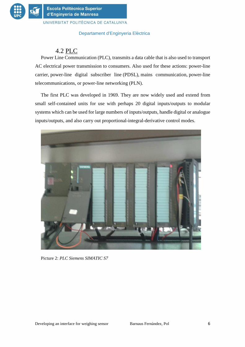
4.2 PLC Power Line Communication (PLC), transmits a data cable that is also used to transport
AC electrical power transmission to consumers. Also used for these actions: power-line
carrier, power-line digital subscriber line (PDSL), mains communication, power-line
telecommunications, or power-line networking (PLN).
The first PLC was developed in 1969. They are now widely used and extend from
small self-contained units for use with perhaps 20 digital inputs/outputs to modular
systems which can be used for large numbers of inputs/outputs, handle digital or analogue
inputs/outputs, and also carry out proportional-integral-derivative control modes.
Picture 2: PLC Siemens SIMATIC S7

Departament d’Enginyeria Elèctrica
Developing an interface for weighing sensor Barnaus Fernàndez, Pol 7
4.2.1 WHAT IS THE FUNCTION OF PLC A basic PLC system consist of a transmitter unit capable of adding the communication
signal to the AC power line signal and receiver unit capable of separating the
communication signal from AC power component signal.
In an ideal PLC system, the output signal of the receiver is a perfect copy of the signal
which was introduced to the transmitter. Is any signals which may impinge upon the
system from a source other than the transmitter are ignored by the receptor. The ideal
PLC system should furthermore not become a source of noise either through direct
transmission or by radiation.
In previous circuits, PLC systems has been used for relatively low carrier frequencies
of 160 Kilohertz (KHz) to 455 Kilohertz (KHz). Some PLC can use a frequency as high
as 1.5 Megahertz (MHz).
The AC power line may broadcast the communication signal. This creates noise which
may interfere with other communication signals. If the communication signal strength is
too low, the signal will be overpowered by the level of noise on the line. If the
communication signal is strong and is a very high frequency, the power line may begin
to radiate and thus violate government regulations regarding interface and harmful
radiation levels.
Picture 3: The PLC system
Departament d’Enginyeria Elèctrica
Developing an interface for weighing sensor Barnaus Fernàndez, Pol 8
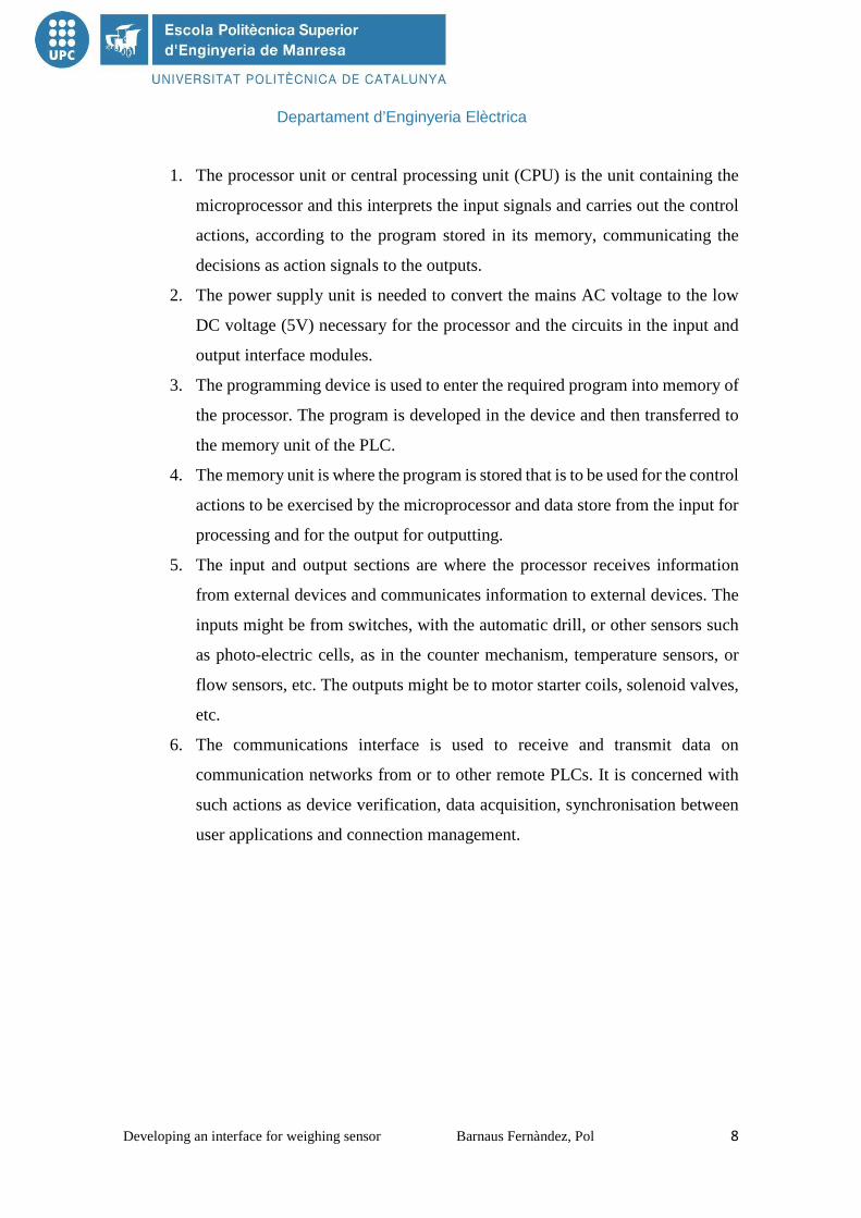
1. The processor unit or central processing unit (CPU) is the unit containing the
microprocessor and this interprets the input signals and carries out the control
actions, according to the program stored in its memory, communicating the
decisions as action signals to the outputs.
2. The power supply unit is needed to convert the mains AC voltage to the low
DC voltage (5V) necessary for the processor and the circuits in the input and
output interface modules.
3. The programming device is used to enter the required program into memory of
the processor. The program is developed in the device and then transferred to
the memory unit of the PLC.
4. The memory unit is where the program is stored that is to be used for the control
actions to be exercised by the microprocessor and data store from the input for
processing and for the output for outputting.
5. The input and output sections are where the processor receives information
from external devices and communicates information to external devices. The
inputs might be from switches, with the automatic drill, or other sensors such
as photo-electric cells, as in the counter mechanism, temperature sensors, or
flow sensors, etc. The outputs might be to motor starter coils, solenoid valves,
etc.
6. The communications interface is used to receive and transmit data on
communication networks from or to other remote PLCs. It is concerned with
such actions as device verification, data acquisition, synchronisation between
user applications and connection management.
Departament d’Enginyeria Elèctrica
Developing an interface for weighing sensor Barnaus Fernàndez, Pol 9
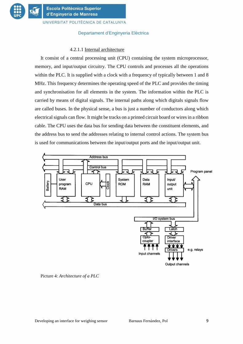
4.2.1.1 Internal architecture
It consist of a central processing unit (CPU) containing the system microprocessor,
memory, and input/output circuitry. The CPU controls and processes all the operations
within the PLC. It is supplied with a clock with a frequency of typically between 1 and 8
MHz. This frequency determines the operating speed of the PLC and provides the timing
and synchronisation for all elements in the system. The information within the PLC is
carried by means of digital signals. The internal paths along which digitals signals flow
are called buses. In the physical sense, a bus is just a number of conductors along which
electrical signals can flow. It might be tracks on a printed circuit board or wires in a ribbon
cable. The CPU uses the data bus for sending data between the constituent elements, and
the address bus to send the addresses relating to internal control actions. The system bus
is used for communications between the input/output ports and the input/output unit.
Picture 4: Architecture of a PLC

Departament d’Enginyeria Elèctrica
Developing an interface for weighing sensor Barnaus Fernàndez, Pol 10
4.2.1.1.1 The CPU
The internal structure of the CPU depends on the microprocessor concerned. In general
they have:
1. An arithmetic and logic unit (ALU) which is responsible for data manipulation
and carrying out arithmetic operations of addition and subtraction and logic
operations of AND, OR, NOT and EXCLUSIVE-OR.
2. The memory, termed registers, located within the microprocessor and used to
store information involved in program execution.
3. A control unit which is used to control the timing of operations.
4.2.1.1.2 The buses
The buses are the paths used for communication within the PLC. The information is
transmitted in binary form, which is as a group of bits with a bit being a binary digit of 1
or 0 that is ON/OFF states. The term word is used for the group of bits constituting some
information. So an 8-bit word might be the binary number 00100110. Each of the bits is
communicated simultaneously along its own parallel wire. The system has four buses:
1. The data bus carries the data used in the processing carried out by the CPU. A
microprocessor termed as being 8-bit has an internal data bus which can handle
8-bit numbers. In this way, you can perform operations between 8-bit numbers
and deliver results as 8-bits values.
2. The address bus is used to carry the addresses of memory locations. So that
each word can be located in the memory, every memory location is given a
unique address. Just like houses in a town are each given a distinct address so
that they can be located, so each word location is given an address so that data
stored at a particular location can be accessed by the CPU either to read data
located there or put, that is, write, data there. It is the address bus which carries
the information indicating which address is to be accessed. If the address bus
consist of 8 lines, the number of 8-bit words, and hence number of distinct
addresses, is 28=256. With 16 address lines, 65536 addresses are possible.

Departament d’Enginyeria Elèctrica
Developing an interface for weighing sensor Barnaus Fernàndez, Pol 11
3. The control bus carries the signals used by the CPU for control, for instance to
inform memory devices whether they are to receive data from an input or
output data and to carry timing signals used to synchronise actions.
4. The system bus is used for communications between the input/output ports and
the input/output unit.
4.2.1.1.3 Memory
There are several memory elements in a PLC system:
1. System read-only-memory (ROM) to give permanent storage for the operating
system and fixed data used by the CPU.
2. Random-access memory (RAM) for the user’s program.
3. Random-access memory (RAM) for data. This is where information is stored
on the status of inputs and outputs devices and the values of timers and counters
and other internal devices. The data RAM is sometimes referred to as a data
table or register table. Part of this memory, that is a block of addresses, will be
reserved for input and output addresses and the states of those inputs and
outputs. Part will be set aside for present data and part for storing counter
values, timer values, etc.
4. Possibly, as a bolt-on extra module, erasable and programmable read-only-
memory (EPROM) for RAMs that can be programmed and then the program
made permanent.
The programs and data in RAM can be changed by the user. All PLCs will have some
amount of RAM to store programs that have been developed by the user and program
data. However, to prevent the loss of programs when the power supply is switched off, a
battery is used in the PLC to maintain the RAM contents for a period of time. After a
program has been developed in RAM it may be loaded an EPROM memory chip, often a
bolt-on module to the PLC, and so made permanent. In addition there are temporary
buffer stores for the input/output channels.
Departament d’Enginyeria Elèctrica
Developing an interface for weighing sensor Barnaus Fernàndez, Pol 12
4.2.1.1.4 Input/output unit
The input/output unit provides the interface between the system and the outside world,
allowing for connections to be made through input/output channels to input devices such
as sensors and output devices such as motors and solenoids. It is also through the
inputs/outputs unit that programs are entered from a program panel. Every input/output
point has a unique address which can be used by the CPU. It is like a row of houses along
a road, number 10 might be the ‘house’ to be used for output to a particular motor.
The input/output channels provide isolation and signal conditioning functions so that
sensors and actuators can often be directly connected to them without the need for other
circuitry. Electrical isolation from the external world is usually by means of optoisolators
(the term optocoupler is also often used). When a digital pulse passes through the light-
emitting diode, a pulse of infrared radiation is produced. This pulse is detected by the
phototransistor and gives rise to a voltage in that circuit. The gap between the light-
emitting diode and the phototransistor gives electrical isolation but the arrangement still
allows for a digital pulse in one circuit to give rise to a digital pulse in another circuit.
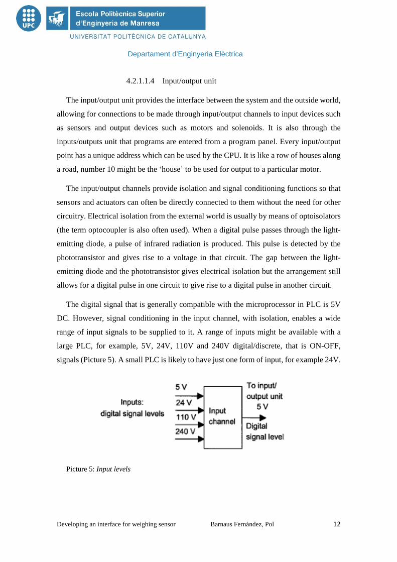
The digital signal that is generally compatible with the microprocessor in PLC is 5V
DC. However, signal conditioning in the input channel, with isolation, enables a wide
range of input signals to be supplied to it. A range of inputs might be available with a
large PLC, for example, 5V, 24V, 110V and 240V digital/discrete, that is ON-OFF,
signals (Picture 5). A small PLC is likely to have just one form of input, for example 24V.
Picture 5: Input levels

Departament d’Enginyeria Elèctrica
Developing an interface for weighing sensor Barnaus Fernàndez, Pol 13
The output from the input/output unit will be digital with a level of 5V. However, after
signal conditioning with relays, transistors or triacs, the output from the output channel
might be a 24V, 100mA switching signal, a DC voltage of 110V, 1A or perhaps 240V,
1A AC, or 240V, 2A AC, from a triac output channel. With a small PLC, all the outputs
might be of one type, for example 240V AC, 1A. With modular PLCs however, a range
of outputs can be accommodated by selection of the modules to be used.
Picture 6: Output levels
Outputs are specified as being of relay type, transistor type or triac type:
1. With the relay type, the signal from the PLC output is used to operate a relay
and is able to switch currents of the order of a few amperes in external circuit.
The relay not only allows small currents to switch much larger currents but
also isolates the PLC from the external circuit. Relays are, however, relatively
slow to operate. Relay outputs are suitable for AC and DC switching. They can
withstand high surge currents and voltage transients.
2. The transistor type of output uses a transistor to switch current through the
external circuit. This gives a considerably faster switching action. It is,
however, strictly for DC switching and is destroyed by overcurrent and high
reverse voltage. As a protection, either a fuse or built-in electronic protection
are used. Optoisolators are used to provide isolation.
3. Triac outputs, with optoisolators for isolation, can be used to control external
loads which are connected to the AC power supply. It is strictly for AC
operation and is very easily destroyed by overcurrent. Fuses are virtually
always included to protect such outputs.
Departament d’Enginyeria Elèctrica
Developing an interface for weighing sensor Barnaus Fernàndez, Pol 14
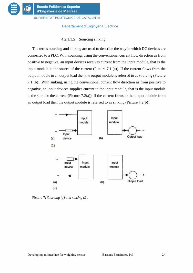
4.2.1.1.5 Sourcing sinking
The terms sourcing and sinking are used to describe the way in which DC devices are
connected to a PLC. With sourcing, using the conventional current flow direction as from
positive to negative, an input devices receives current from the input module, that is the
input module is the source of the current (Picture 7.1 (a)). If the current flows from the
output module to an output load then the output module is referred to as sourcing (Picture
7.1 (b)). With sinking, using the conventional current flow direction as from positive to
negative, an input devices supplies current to the input module, that is the input module
is the sink for the current (Picture 7.2(a)). If the current flows to the output module from
an output load then the output module is referred to as sinking (Picture 7.2(b)).
Picture 7: Sourcing (1) and sinking (2).
Departament d’Enginyeria Elèctrica
Developing an interface for weighing sensor Barnaus Fernàndez, Pol 15
4.2.2 APLICATIONS OF PLC TECHNOLOGY 4.2.2.1 Indoor or short range
It is typical of home automation, electrical installation of the house was used as a
transmission medium, such as lighting control and other electrical devices without the
need to install additional wiring or distribution of video, television, music or the Internet
to access it anywhere in the house.
Usually these device operate by injecting a high frequency carrier signal on the wiring
of the house. This carrier signal is modulated with digital signals. Each receiver system
has an address that identifies you and allows you to be individually managed, so that only
the decoded data sent to this address. This device can be connected to standard plugs or
be permanently connected to the electrical installation. Because these signal can
propagate to neighboring homes belonging to the same distribution system, there is a
network ID to refer to the owner and prevents the data received may be transported out
of the house.
4.2.2.2 Outdoor or long range
Use medium and low voltage lines to provide service to broadband Internet access,
video distribution and television or in mobile what is called the local loop or last mile that
is the connection from the central different telephone subscribers. This enables a
telecommunications infrastructure much cheaper than others such as fibre optic or coaxial
cable, which allows sending data speeds of up to 200 Mbit/s and also has coverage
potential wider.
There exists an intermediate between this group and the previous data that is to provide
service (broadband Internet and/or distribution TV) to multiple users (homes) for large
buildings such as skyscrapers.
Within this group, the standard emphasizes open access through PLC promoted by the
European Union, known as OPERA (Open PLC European Research Alliance).
Utility companies use special coupling capacitors to connect radio transmitters to the
power-frequency AC conductors. Frequencies used are in the range of 24 to 500 kHz,
with transmitter power levels up to hundreds of watts. These signals may be impressed
on one conductor, on two conductors or on all three conductors of a high-voltage AC

Departament d’Enginyeria Elèctrica
Developing an interface for weighing sensor Barnaus Fernàndez, Pol 16
transmission line. Several PLC channels may be coupled onto one HV line. Filtering
devices are applied at substations to prevent the carrier frequency current from being
bypassed through the station apparatus and to ensure that distant faults do not affect the
isolated segments of the PLC system. These circuits are used for control of switchgear,
and for protection of transmission lines. For example, a protective relay can use a PLC
channel to trip a line if a fault is detected between its two terminals, but to leave the line
in operation if the fault is elsewhere on the system.
While utility companies use microwave and now, increasingly, fibre optic cables for
their primary system communication needs, the power-line carrier apparatus may still be
useful as a backup channel or for very simple low-cost installations that do not warrant
installing fibre optic lines.
Power-line carrier communication (PLCC) is mainly used for telecommunication,
tele-protection and tele-monitoring between electrical substations through power
lines at high voltages, such as 110 kV, 220 kV, 400 kV. The major benefit is the union of
two applications in a single system, which is particularly useful for monitoring electric
equipment and advanced management techniques (such as OpenADR and OpenHAN).
The modulation generally used in these system is amplitude modulation. The carrier
frequency range is used for audio signals, protection and a pilot frequency. The pilot
frequency is a signal in the audio range that is transmitted continuously for failure
detection.
The voice signal is compressed and filtered into the 300 Hz to 4000 Hz range, and this
audio frequency is mixed with the carrier frequency. The carrier frequency is again
filtered, amplified and transmitted. The transmission power of these HF carrier
frequencies will be in the range of 0 to +32 dBW. This range is set according to the
distance between substations. PLCC can be used for interconnecting private branch
exchanges (PBXs).
To sectionalize the transmission network and protect against failures, a wave trap is
connected in series with the power (transmission) line. They consist of one or more
sections of resonant circuits, which block the high frequency carrier waves (24 kHz to
500 kHz) and let power frequency current (50 Hz – 60 Hz) pass through. Wave traps are

Departament d’Enginyeria Elèctrica
Developing an interface for weighing sensor Barnaus Fernàndez, Pol 17
used in switchyard of most power stations to prevent carrier from entering the station
equipment. Each wave trap has a lightning arrester to protect it from surge voltages.
A coupling capacitor is used to connect the transmitters and receivers to the high
voltage line. This provides low impedance path for carrier energy to HV line but blocks
the power frequency circuit by being a high impedance path. The coupling capacitor may
be part of a capacitor voltage transformer used for voltage measurement.
Power-line carriers may change its transmission system from analogue to digital to
enable Internet Protocol devices. Digital power-line carrier (DPLC) was developed for
digital transmission via power lines. DPLC has the required quality of bit error rate
characteristics and transmission ability such as transmitting information from monitored
electric-supply stations and images.
4.2.2.3 Wiring home networks (broadband)
PLC technology can also be used in the networking of home computers and peripheral
devices, including those that require network connections, although at present there are
no standards for this type of application. Existing standards or standards have been
developed by different companies within the framework defined by the U.S.
organizations Home Plug Power line Alliance and Universal Power line Association.
4.2.2.4 Power management
Currently, power companies are working on improving this technology in mind control
and monitoring of energy. The model of creating electricity is increasingly dispersed, that
is power generation does not occur only in large central but distributed way. An example
of this monitoring are electric meters that are starting to install some blocks and allow the
utility company to obtain the power consumption of the subscriber in real time.
4.2.2.5 Other applications
PLC technology is also being studied and applied in cars because that way it saves
weight by using the same cable to send communications and energy.

Departament d’Enginyeria Elèctrica
Developing an interface for weighing sensor Barnaus Fernàndez, Pol 18
4.2.3 ADVANTAGES � Cost savings in infrastructure because it uses the existing electrical
infrastructure. Not needed works.
� Flexible technology, topology and network features can be modified easily to
mind.
� Easy to install.
� The electrical plug is taken only for power, voice and data. No interference
with the electricity supply.
� The services offered are competitive in price and quality, is a valid alternative
to ADSL (Asymmetric Digital Subscriber Line) and CATV (cable television).
� Can integrate different services on the same network (telephony, internet
access, television distribution...) and may even have different networks on the
same electrical installation, thanks to the temporal multiplexing or frequency.
4.2.4 DISADVANTAGES � Depending on the frequencies used and technology, can produce radiation in
bands HF, interfering frequencies used by emergency and security forces and
the amateur side. That is why some governments such as the Americans and
Japanese had opposed PLC deployments in the past. Today, however, there are
devices that allow the PLC to select the frequency at which it is transmitted, it
is the case, for example, chip technology company DS2.
� The profitability of these services is not always assured.

Departament d’Enginyeria Elèctrica
Developing an interface for weighing sensor Barnaus Fernàndez, Pol 19
4.3 SIWAREX U SIWAREX U (Picture 8) is a versatile weighing module for all simple tasks of
weighing and force measurement. The module compact can be used seamlessly with
PLC’s SIMATIC programmable. In this case, the total data access it is possible via the
SIMATIC.
Picture 8: SIWAREX U
4.3.1 DESIGN SIWAREX U is a function module (FM) of the SIMATIC S7-300 can be snapped
directly to the backplane bus SIMATIC S7-300 or ET 200M. The assembling and wiring
are considerably simplified thanks to the mounting rails (Snap-on mounting) (Picture 8).
The connection of the load cells, power supply and serial ports is performed by the
standard 20-pin front connector.
The operation of SIWAREX U in SIMATIC guarantees complete integration of
technology weighing PLC.

Departament d’Enginyeria Elèctrica
Developing an interface for weighing sensor Barnaus Fernàndez, Pol 20
Picture 9: System overview with SIWAREX U
4.3.2 FUNCTION SIWAREX U is available with either one or two measurement channels. Measurement
channel is required for each scale.
The main function of SIWAREX U is to measure the voltage sensors and convert it
into a weight value. If is necessary, the signal can be digitally filtered.
As well as determining weighing SIWAREX monitors two channel limit as it can
freely set values (ex. Min. / Max.).
The SIWAREX U are factory-calibrated. This will be theoretical adjustment of the
balance without weights, and you can change the module without renewed adjustment of
scale. And if "active bus" used the modules can even be changed on the fly.
Consistent and uniform communication between all system components enables the
integration and the fast, reliable and diagnosis in industrial processes.
SIWAREX U has two serial ports. One the TTY port lets you connect up to four digital
remote displays. In these, besides the two weights weighing channels 1 and 2 can be
Departament d’Enginyeria Elèctrica
Developing an interface for weighing sensor Barnaus Fernàndez, Pol 21
displayed two values on the remote displays more defined via SIMATIC. The other
RS232 port, can connect a PC to adjust the balance.
SIWAREX U not only integrates into the application software with classic
programming languages for PLC, that is, STL (Statement List), LD (Ladder Diagram)
SFC (Sequential Function Chart) or SCL (Structured Control Language ). There is also
the possibility of a graphical configuration CFCs (Continuous Function Chart) using
images simulated or "faceplates" provided by PCS 7 for displaying scales.
Faced with the electronic modules connected in series, with SIWAREX U the high
cost of additional modules are deleted typically required for connection to SIMATIC S7.
Integration in SIMATIC allows you to configure systems weighing of modular
structure and free programmable, which can adapt to the internal requirements of each
company.
The SIWATOOL U software adjusts the SIWAREX with the usual comfort of
Windows, with independency of the PLC. All specifications for weighing modules can
be defined in entry screens and saved and printed out on a printer reports to document the
processes of the production plant.
The online mode also ensures early detection of errors through various diagnostic
options offered SIWATOOL U.
The module SIWAREX U is also suitable for classified areas. There is the possibility
to realize feeding the load cells with intrinsically safe by means of optional Ex interface.
Departament d’Enginyeria Elèctrica
Developing an interface for weighing sensor Barnaus Fernàndez, Pol 22
4.3.3 ADVANTAGES � Uniform design system and consistent communication in SIMATIC.
� Application in the distributed system connected thanks to PROFIBUS DB
/PROFINET via ET200M.
� Measurement of weight or force with a high resolution of 65000 parts and an
accuracy of 0.05%.
� Space saving by applying the two-channel version for two scales.
� Direct connection of a remote display to the TTY interface.
� Simple Parameterizing with SIWATOOL.
� Supports replacement of module without renewed adjustment of scale.
� Supports theoretical adjustment without adjustment weights.
� Intrinsically-safe load cell supply for the hazardous area zones 1,2 (optional).
� Can be used for Ex-applications.
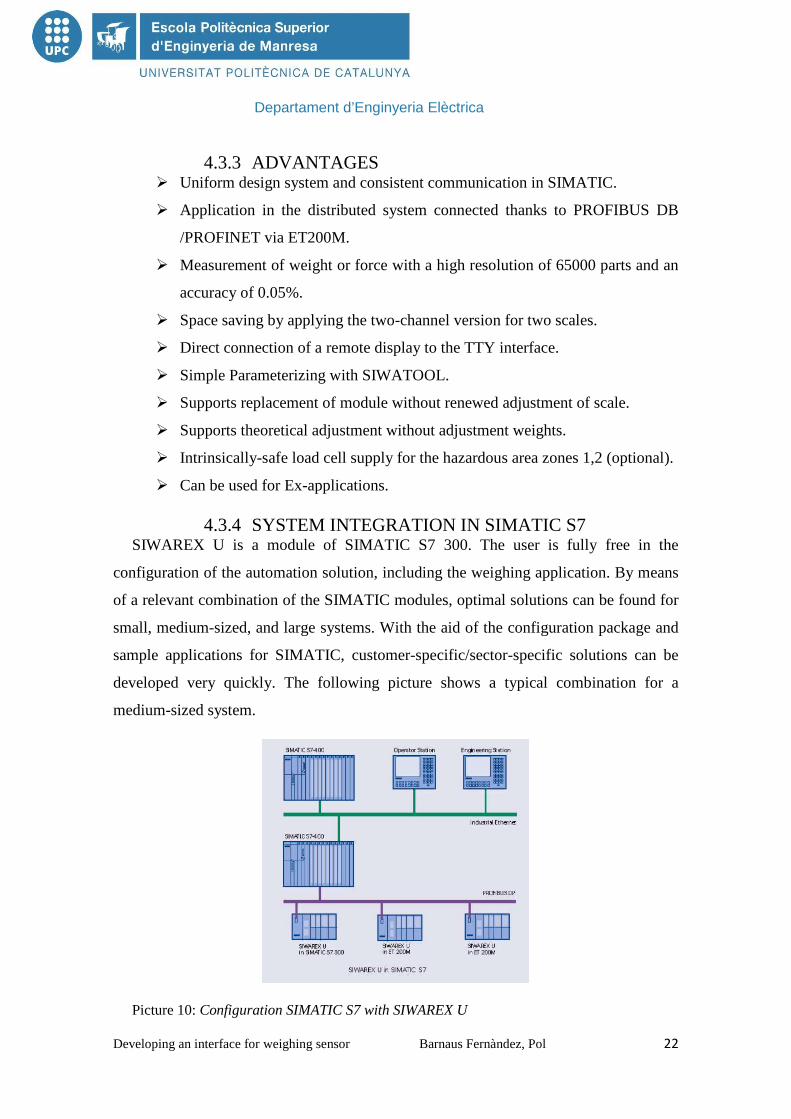
4.3.4 SYSTEM INTEGRATION IN SIMATIC S7 SIWAREX U is a module of SIMATIC S7 300. The user is fully free in the
configuration of the automation solution, including the weighing application. By means
of a relevant combination of the SIMATIC modules, optimal solutions can be found for
small, medium-sized, and large systems. With the aid of the configuration package and
sample applications for SIMATIC, customer-specific/sector-specific solutions can be
developed very quickly. The following picture shows a typical combination for a
medium-sized system.
Picture 10: Configuration SIMATIC S7 with SIWAREX U

Departament d’Enginyeria Elèctrica
Developing an interface for weighing sensor Barnaus Fernàndez, Pol 23
4.4 SIMATIC S7 4.4.1 DESCRIPTION
SIMATIC S7-300 controller saves on installation space and features a modular design.
A wide range of modules can be used to expand the system centrally or to create
decentralized structures according to the task at hand, and facilitates a cost-effective stock
of spare parts.
The multi-facetted module range allows modular customization to suit the most varied
tasks.
Function modules are intelligent modules that independently execute the technological
tasks like counting, measuring, cam control, PID control and motion control. Therefore
they reduce the load on the CPU. They are used when a high level of accuracy and
dynamic response is required.
4.4.2 ADVANTATGES � High degree of accuracy and dynamic response.
� Specialized and universal modules with a wide range of functions.
� CPU is not involved since the functionality is stored in the firmware of each
module.
� Quick reaction times (deterministic dynamic response).
� Engineering with configuring tool, integrated into STEP 7.
� The S7-300's range of CPUs provides the right solution for every application,
and customers only pay for the performance actually required for a specific
task.
� Integral PROFINET interfaces enable simple networking of the controllers,
and simple data exchange with the operations management level.
� The narrow module width results in a compact controller design or a small
control cabinet.
� The ability to integrate powerful CPUs with Industrial Ethernet/PROFIBUS
interface, integrated technological functions, or fail-safe designs make
additional investments unnecessary.

Departament d’Enginyeria Elèctrica
Developing an interface for weighing sensor Barnaus Fernàndez, Pol 24
4.5 SIWAREX R
Picture 11: SIWAREX R
SIWAREX R load cells are used for static and dynamic measurements of forces and
weights. They can be used for almost all applications in industrial weighing technology.
These may be for example:
� Container, hopper or platform scales.
� Rollway, belt or crane scales.
� Filling/packing plants, proportioning and mixing.
� Filling level and completeness inspection.
� Equipment for monitoring pressing and clamping procedures.
� Dynamic scales.
All applications can be located in areas with mandatory calibration or in hazardous
areas.
The measuring element is a double bending beam made of stainless steel to which 4
strain gauges are applied. The strain gauges are arranged so that two are stretched and
two are compressed.
Departament d’Enginyeria Elèctrica
Developing an interface for weighing sensor Barnaus Fernàndez, Pol 25
Under the influence of the load acting in the measuring direction, the spring bodies
and therefore the friction-locked strain gauges are elastically deformed. This generates a
measuring signal voltage that is proportional to the load.
4.6 SIMANTIC PANEL TOUCH For this project used SIMANTIC PANEL TOUCH for operator control and
monitoring. In this case it use OP1778B HMI device. This panel is versatile that could
use with key or touching depends the things you need to make.
Is necessary make one configuration with WinCC flexible 2008 for use the panel. This
combination had specials highlights.
� Freely definable message classes (acknowledgement behaviour and
representation can be configured).
� Graphics and texts can be switched language-dependent and are freely scalable.
� Permanent window and template concept for creating screen templates.
� Message history is retained even with devices switched off – and without
battery.
� Online language switchover with 5 selectable languages, incl. Asian and
Cyrillic fonts.
� Analog signals (limit signals) as well as bit signals to display plant statuses.
� Recipe data sets can already be flexibly prepared off-line when configuring.
� User administration (security) – authentication by means of user ID and
password can also be edited off-line.
� Privileges specific to user groups are an integral component of the user
administration.

Departament d’Enginyeria Elèctrica
Developing an interface for weighing sensor Barnaus Fernàndez, Pol 26
4.7 WINCC FLEXIBLE 2008 WinCC flexible 2008 software package provides the development environment
Siemens under the scadas for visualization and industrial process control. Its most
important features can be summarized as:
� Open Architecture development (programming in C).
� Support Active X technologies.
� Communication with other applications via OPC.
� Easy communication with drivers (code that implements the communications
protocol with a specific intelligent computer) implemented.
� Online Programming: is not necessary to stop the development runtime to
update the changes in the same.
Picture 12: Main screen of WinCC flexible 2008
Departament d’Enginyeria Elèctrica
Developing an interface for weighing sensor Barnaus Fernàndez, Pol 27
Main screen for use WinCC flexible 2008.
� Project Explorer: It is located to the left of the window. Here you can explore
all the settings related to the project. In this part we access the variables created
and connections located in the communications section. Besides this you can
perform other tasks such as creating recipes, scripts structures ...
� Workspace: Located in the central part of the project window. Here using the
graphical editor we can create the shapes we want giving different animations
as: visibility, appearance flickering movements....
� Tools: In this part we have various tools such as: Simple geometric shapes
(line, circle, square, polyline ...), Date field, text field, button, switch ... Here
we can also access libraries already created or imported by us.
Departament d’Enginyeria Elèctrica
Developing an interface for weighing sensor Barnaus Fernàndez, Pol 28
5. METHODS 5.1 ESTABLISH AND ADJUSTMENT THE
COMMUNICATION TO THE SIWAREX U MODULE
First of all is necessary communicated the SIWATOOL U and SIWAREX U if it the
next process want to be available. Following is an explanation of how to make the
connection.
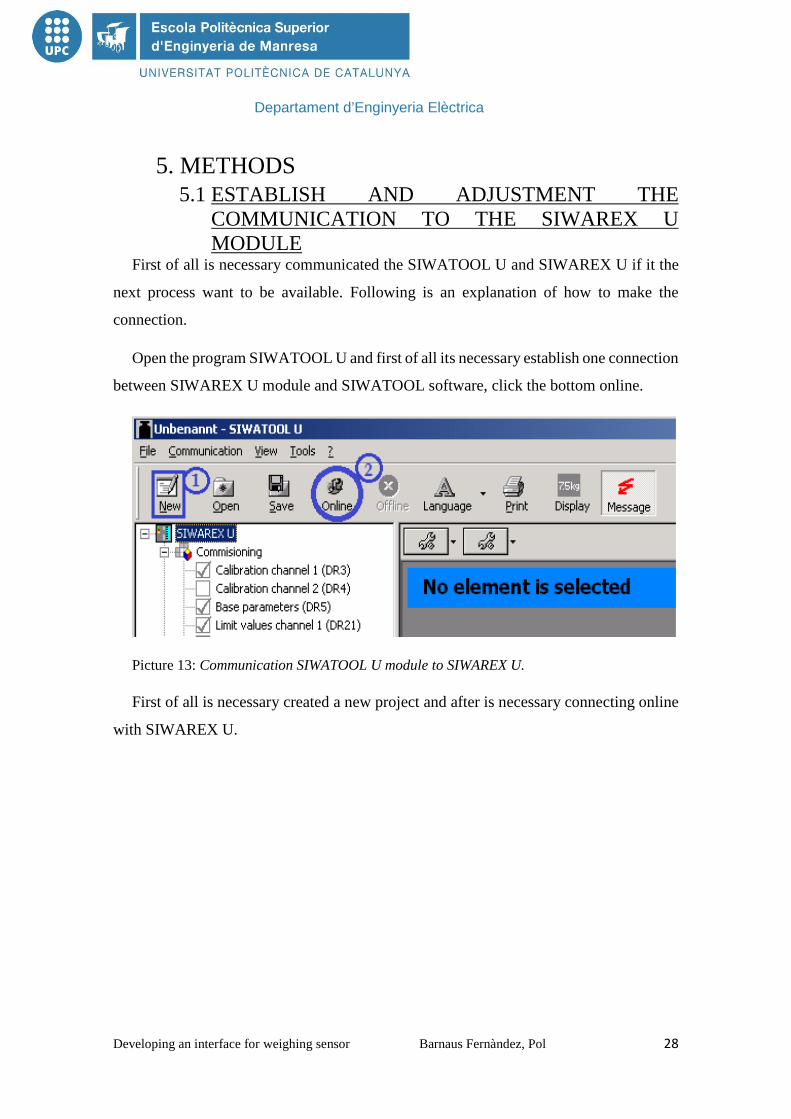
Open the program SIWATOOL U and first of all its necessary establish one connection
between SIWAREX U module and SIWATOOL software, click the bottom online.
Picture 13: Communication SIWATOOL U module to SIWAREX U.
First of all is necessary created a new project and after is necessary connecting online
with SIWAREX U.

Departament d’Enginyeria Elèctrica
Developing an interface for weighing sensor Barnaus Fernàndez, Pol 29
When the communication is established check the following parameter-settings:
Picture 14: Calibration of SIWATOOL U
1. Press the button “New”.
2. Press the button “Online”.
3. Press the button “Display”.
4. Without any weight on the weighing scale press the button “Adjust zero
valid (1)”.
5. Put 2Kg load, provided with the weighing kit in the sensor and adjust
the proprieties in SIWAREX > Commissioning > Calibration Channel
1(DR3) and in Adjustment Weight for the value of 2000 (g), and after
press Send.
6. Press the button “Adjustment weight valid (2).”
7. Finally you need to save the new scale, for that press the button “save”.
Once completed these steps, the next time you open the project with WinCC or Touch
panel the scale be saved.
Departament d’Enginyeria Elèctrica
Developing an interface for weighing sensor Barnaus Fernàndez, Pol 30
5.2 HARDWARE CONFIGURATION IN SIMATIC S7 After the connection of SIWATOOL U it is the moment for start the configuration of
SIMATIC S7. This is the program where it creates the program for PLC. Is essential make
correctly the configuration of hardware, as every project needed a personal configuration.
For this project it necessary the next configuration:
� First is necessary create a new project in SIMATIC S7.
� One time made this is necessary this steps:
• Name of the project > SIMATIC_S7 > CPU314 > Hardware
In this moment click two times Hardware and appear a new page, this page
is the place where it make the configuration.
� Before start the configuration is the moment for choose the PLC that is being
used. In this case is used SIMATIC-300. To choose the program is provided
on the right side of the screen. Is very important select the correct Hardware,
in this case CPU314.
• SIMATIC 300 > Rack-300 > CPU314
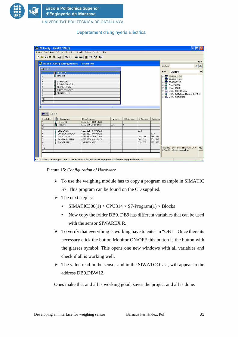
� Now is the time to start configuring. Is very important put the racks or modules
in the correct position, in the picture 15 below you can see how you have to
put the racks in this project. The names and numbers of every module and racks
can be found in their specifications.
� When the configuration is done is the moment for save and upload in PLC.
Departament d’Enginyeria Elèctrica
Developing an interface for weighing sensor Barnaus Fernàndez, Pol 31
Picture 15: Configuration of Hardware
� To use the weighing module has to copy a program example in SIMATIC
S7. This program can be found on the CD supplied.
� The next step is:
• SIMATIC300(1) > CPU314 > S7-Program(1) > Blocks
• Now copy the folder DB9. DB9 has different variables that can be used
with the sensor SIWAREX R.
� To verify that everything is working have to enter in “OB1”. Once there its
necessary click the button Monitor ON/OFF this button is the button with
the glasses symbol. This opens one new windows with all variables and
check if all is working well.
� The value read in the sensor and in the SIWATOOL U, will appear in the
address DB9.DBW12.
Ones make that and all is working good, saves the project and all is done.
Departament d’Enginyeria Elèctrica
Developing an interface for weighing sensor Barnaus Fernàndez, Pol 32
6. DEVELOPMENT OF WEIGHING SYSTEM 6.1 LEARNING MODULES
Before starting building the weighing interface first one step is required: to learn how
the programs works. For this was suggested that the student follow the E-learning training
with SIMATIC S7, in the website of the Institut für Automatisierungstechnik
(www.global.hs-mittweida.de/~ifa/).
The learning modules consists of 4 experiments, describe step to step helping the
student to work with this software. They are: 7 segments display, site traffic light, two-
step level controller and PID level controller.
In every experiment there are specific external boards so we can simulate the problem
and fix it. In the website are described how the problem is and give a solution of an
implementation on SIMATIC S7.
It was done exactly as the website describes, and a little of extra work in the system
Site Traffic light, showed below.
6.2 SITE TRAFFIC LIGHT SYSTEM The traffic has to be narrowed because of construction work. There is only one track,
and a traffic light should control the traffic.
Switching on the system (switch S0) - both traffic lights has to signalize RED. If one
initiator (J1 or J2) sends the signal "1" (that's the case when a car is at J1 or J2, which in
real life represented a sensor of proximity), the appropriate traffic light has to become
GREEN after 10 seconds. The green phase must persist at least 20 seconds before both
traffic lights switch to RED if the other initiator is operated possibly. After 10 seconds
the other track is served with green. If no initiator is operated, the traffic light remains in
the last state. Switching off the traffic lights should be allowed only after a green phase.

Departament d’Enginyeria Elèctrica
Developing an interface for weighing sensor Barnaus Fernàndez, Pol 33
The following schematic of the problem, the university module, is shown below in
Picture 16.
Picture 16: Schematic of the problem traffic light system, also learning module.
Departament d’Enginyeria Elèctrica
Developing an interface for weighing sensor Barnaus Fernàndez, Pol 34
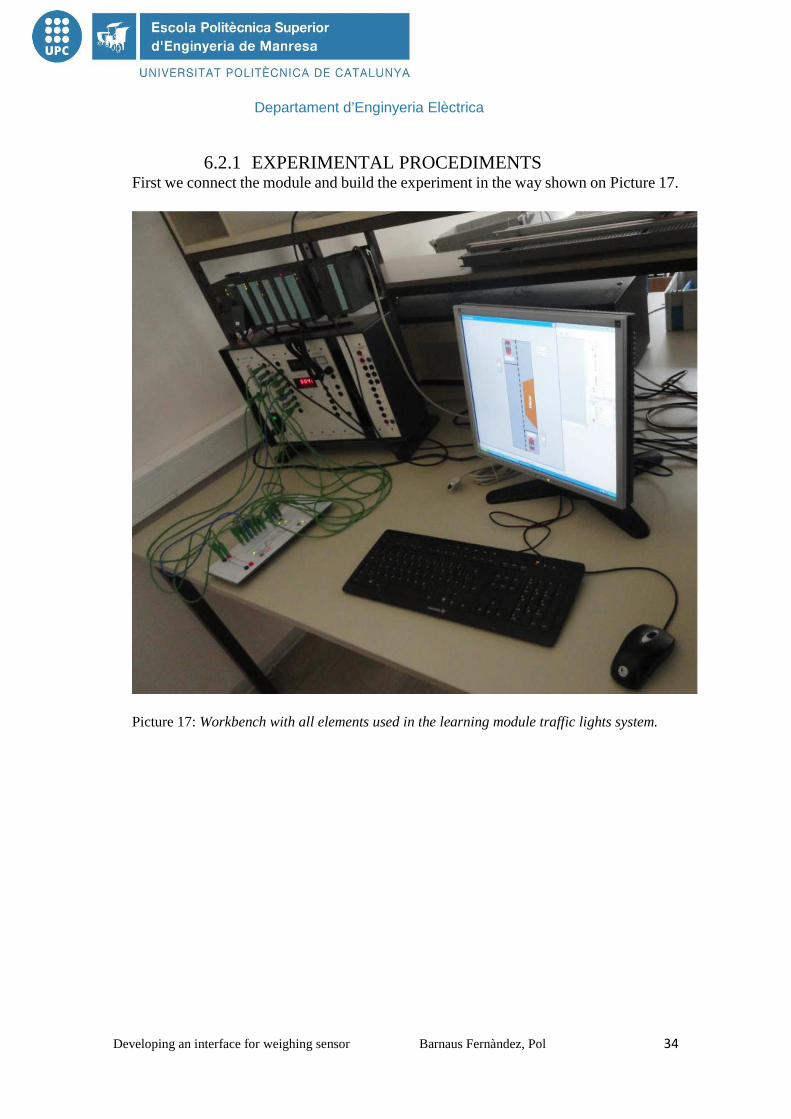
6.2.1 EXPERIMENTAL PROCEDIMENTS First we connect the module and build the experiment in the way shown on Picture 17.
Picture 17: Workbench with all elements used in the learning module traffic lights system.
Departament d’Enginyeria Elèctrica
Developing an interface for weighing sensor Barnaus Fernàndez, Pol 35
The follow Table 1 show all the connections between the modules and the PLC and
the address used in the WinCC Software.
INPUT/OUTPUT VARIABLE DEVICE LOGICAL ALLOCATION Input Switch 0 (S0) I1.0 Switch "ON" I1.0=1 digital input 0 Input Initiator 1(J1) I1.1 Initiator "ON" I1.1=1 digital input 1 Input Initiator 2 (J2) I1.2 Initiator “ON" I1.2=1 digital input 2 Output Green Lamp 1 of J1 (H1) Q4.1 Lamp “ON” Q4.1 = 1 Digital output 1 Output Green Lamp 2 of J2 (H2) Q4.2 Lamp “ON” Q4.2 = 1 Digital output 2 Output Yellow Lamp 1 of J1 (H3) Q4.3 Lamp “ON” Q4.3 = 1 Digital output 3 Output Yellow Lamp 2 of J2 (H4) Q4.4 Lamp “ON” Q4.4 = 1 Digital output 4 Output Red Lamp 1 of J1 (H5) Q4.5 Lamp “ON” Q4.5 = 1 Digital output 5 Output Red Lamp 2 of J2 (H6) Q4.6 Lamp “ON” Q4.6 = 1 Digital output 6
Table 1: Connections between the modules and the PLC and their address.
6.2.2 SOLUTION It becomes evident that the program works as a status machine.
The traffic light can be implemented either in automatic mode or by means of a priority
circuit.
In this case are used the priority circuit. It's important that the input conditions are
interlocked against each other. In the available case, 4 start conditions are possible:
a) There is a car at J1 and J2.
b) There is only a car at J1.
c) There is only a car at J2.
d) There is a car neither at J1 nor at J2.
If the step enabling conditions J1 and J2 (a) are fulfilled at the same time one state has
to be given priority.
The result is a sequence control system, with which the stepping from one step to the
next one takes place dependently on the step-conditions.
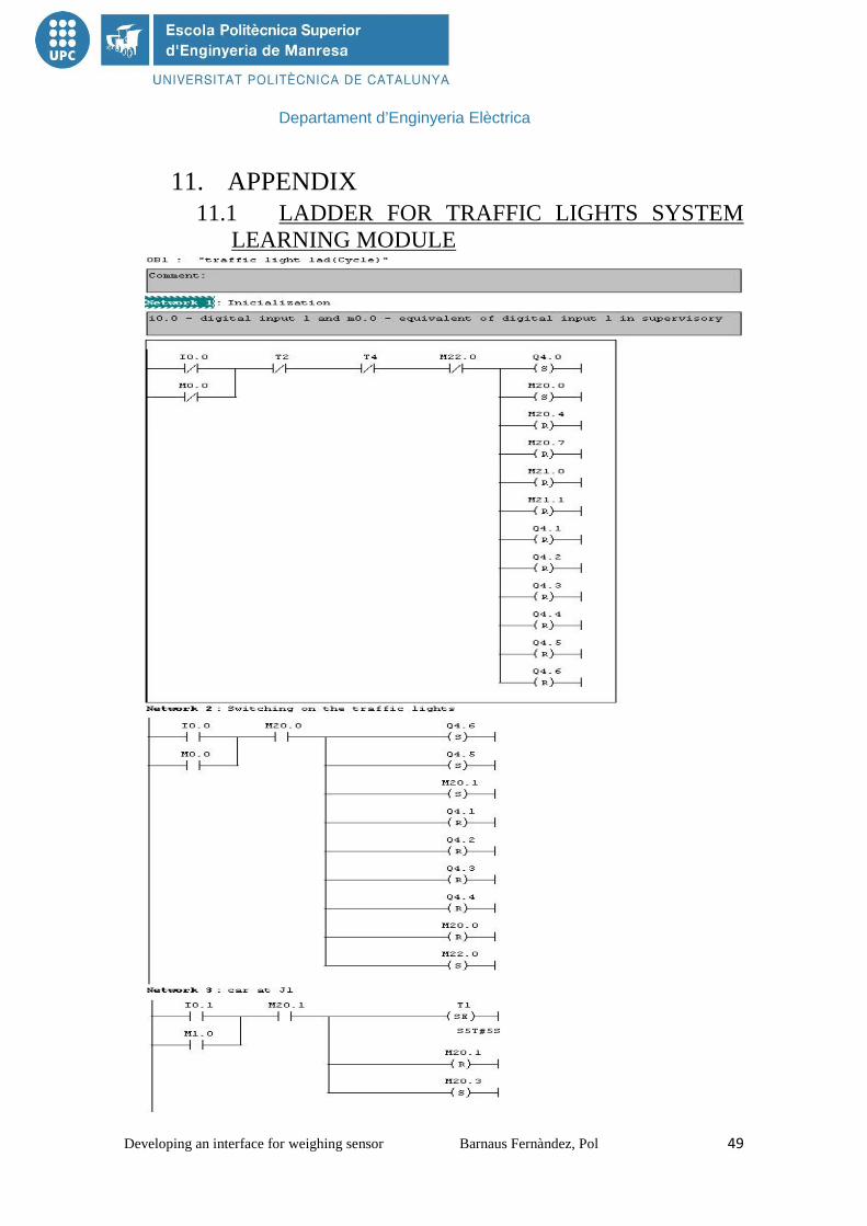
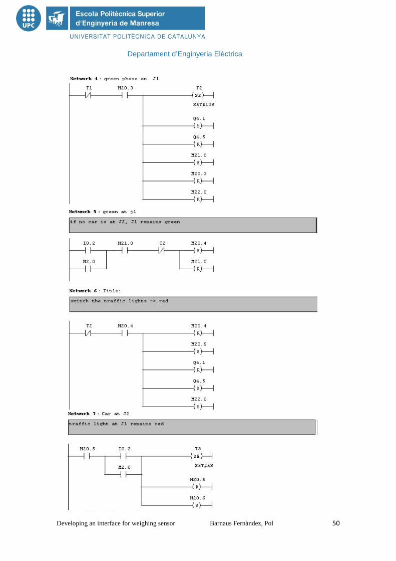
Out of this conditions a ladder program were made and loaded to PLC. This ladder
program can be view in the Attached Documents 1.
Departament d’Enginyeria Elèctrica
Developing an interface for weighing sensor Barnaus Fernàndez, Pol 36
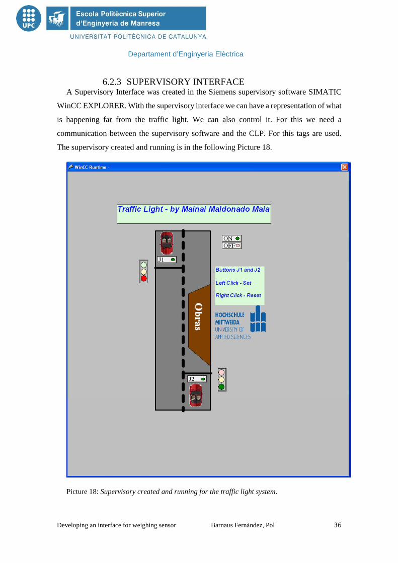
6.2.3 SUPERVISORY INTERFACE A Supervisory Interface was created in the Siemens supervisory software SIMATIC
WinCC EXPLORER. With the supervisory interface we can have a representation of what
is happening far from the traffic light. We can also control it. For this we need a
communication between the supervisory software and the CLP. For this tags are used.
The supervisory created and running is in the following Picture 18.
Picture 18: Supervisory created and running for the traffic light system.

Departament d’Enginyeria Elèctrica
Developing an interface for weighing sensor Barnaus Fernàndez, Pol 37
In this program a tag can be of two different types: Boolean, assuming only values
HIGH or LOW, or Unsigned 8-bits value, assuming integer values. In the Picture 19 the
tags created are showed and their type and their address on the PLC.
Picture 19: Tags used in the traffic lights system supervisory.
Departament d’Enginyeria Elèctrica
Developing an interface for weighing sensor Barnaus Fernàndez, Pol 38
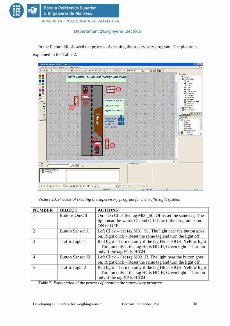
In the Picture 20, showed the process of creating the supervisory program. The picture is
explained in the Table 2.
Picture 20: Process of creating the supervisory program for the traffic light system.
NUMBER OBJECT ACTIONS 1 Buttons On/Off On – On Click Set tag M00_S0, Off reset the same tag. The
light near the words On and Off show if the program is on ON or OFF
2 Button Sensor J1 Left Click – Set tag M01_S1. The light near the button goes on. Right click – Reset the same tag and turn the light off.
3 Traffic Light 1 Red light – Turn on only if the tag H5 is HIGH, Yellow light – Turn on only if the tag H3 is HIGH, Green light – Turn on only if the tag H1 is HIGH
4 Button Sensor J2 Left Click – Set tag M02_J2. The light near the button goes on. Right click – Reset the same tag and turn the light off.
5 Traffic Light 2 Red light – Turn on only if the tag H6 is HIGH, Yellow light – Turn on only if the tag H4 is HIGH, Green light – Turn on only if the tag H2 is HIGH
Table 2: Explanation of the process of creating the supervisory program.

Departament d’Enginyeria Elèctrica
Developing an interface for weighing sensor Barnaus Fernàndez, Pol 39
6.3 WEIGHING SYSTEM The weighing system, including its Hardware, was described in the Material and
Methods section and an Interface for the touch panel was created.
In the Picture 21 is shown the program running in a touch panel.
Picture 21: Weighing system program running in a touch panel.
In the main screen it is possible to see the exactly weight read in the sensor SIWAREX
R. It is possible just because of the library present in the example program. In the main
screen there is also a button “2 measurements operations” that changes the program for
the second screen.
In the second screen “Operations”, the measurement read in the sensor is also shown.
There is two buttons, ‘Acquire Measurement 1’, and ‘Acquire Measurement 2’, to acquire
measurements and work with them. After you click the two buttons for acquire the
measurements, the measurements saved can be seen in the middle of the screen. Also can
be seen a comparison between the two measures, if they are equal or the first measurement
Departament d’Enginyeria Elèctrica
Developing an interface for weighing sensor Barnaus Fernàndez, Pol 40
is greater or lower than the second measurement. In the bottom of the screen can be the
average between the two measurements and a button to return to the first screen.
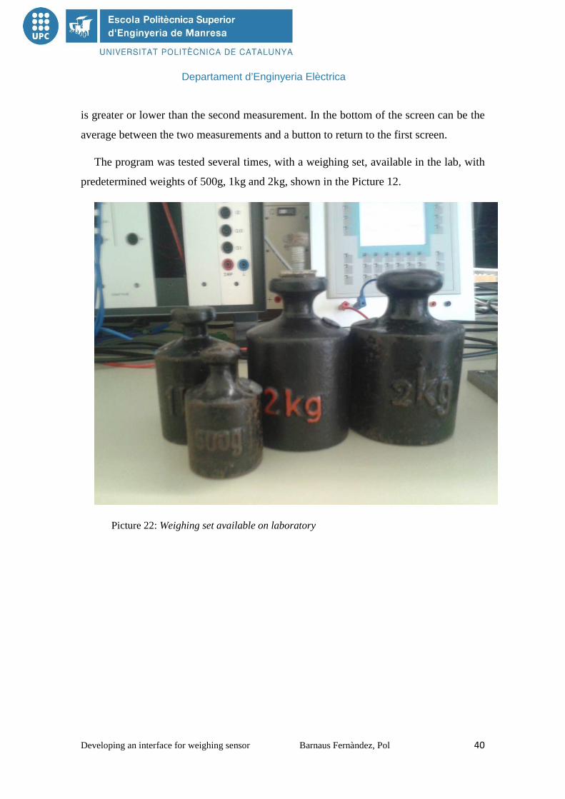
The program was tested several times, with a weighing set, available in the lab, with
predetermined weights of 500g, 1kg and 2kg, shown in the Picture 12.
Picture 22: Weighing set available on laboratory
Departament d’Enginyeria Elèctrica
Developing an interface for weighing sensor Barnaus Fernàndez, Pol 41
6.3.1 DEVELOP OF HARDWARE To create the system the first thing you do is create the Hardware in SIMTIC S7 and
the interface for the panel touch with WinCC flexible 2008. This was explain inside
chapters methods.
The next step is to create the hardware to control the entire process, this has to be
simple and easy to understand, because it will be the one you have to use to create the
interface.
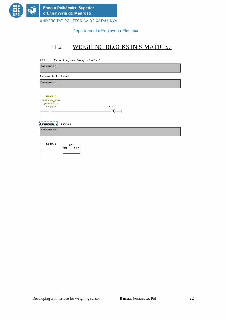
The program is develop with SIMATIC S7, and is necessary use one OB1, FB1 and
for the tag I_Gross_weight_CH1 is necessary the DB9 and UDT9, this is explain inside
chapter hardware configuration in SIMATIC S7. The program create is develop in the
attached documents.
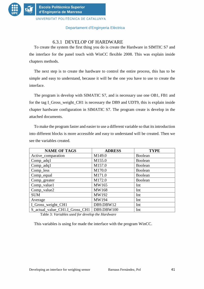
To make the program faster and easier to use a different variable so that its introduction
into different blocks is more accessible and easy to understand will be created. Then we
see the variables created.
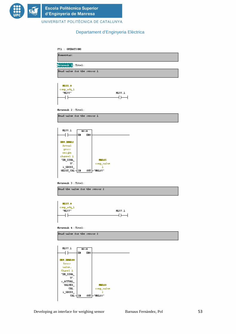
NAME OF TAGS ADRESS TYPE Active_comparation M149.0 Boolean Comp_adq1 M155.0 Boolean Comp_adq1 M157.0 Boolean Comp_less M170.0 Boolean Comp_equal M171.0 Boolean Comp_greater M172.0 Boolean Comp_value1 MW165 Int Comp_value2 MW168 Int SUM MW192 Int Average MW194 Int I_Gross_weight_CH1 DB9.DBW12 Int S_actual_value_CH1.I_Gross_CH1 DB9.DBW100 Int
Table 3: Variables used for develop the Hardware
This variables is using for made the interface with the program WinCC.

Departament d’Enginyeria Elèctrica
Developing an interface for weighing sensor Barnaus Fernàndez, Pol 42
6.3.2 DEVELOP THE INTERFACE Once you create the hardware that will run the PLC is the time to start creating the
interface program. The creation of the interface is free to be the way you want, but it has
to resemble the hardware created. This interface is to be seen on the touch screen, for that
reason we have to do in the simplest way, as they are for workers and has to try to work
as comfortable and fast as possible. For this is very important made clearly the Hardware,
because after is more easy to combine with the interface the most easy way.
With the software WinCC flexible 2008 are created the interface. This interface
consists of 2 screens (Picture 22), the first is main screen and the second is the operations.
The main screen is the screen that you can see the actual weight sensor that reads
SIWAREX R. That is possible only because the variables created inside the Hardware are
introduced in the program. After seeing the weight, there is a button "average" that once
clicked takes you to the operation screen.
Here, first of all, have two buttons “Measurement 1” and “Measurement 2”. This
buttons acquire de measurement, this buttons takes you and other time inside the main
screen.
After this have the values of measurement 1 and 2. This is important to know the
weight that each. Also you can see the comparison among them, if the measurement 1 is
less, greatest or equal than the 2 measurement.
Finally it is possible see the average.
Departament d’Enginyeria Elèctrica
Developing an interface for weighing sensor Barnaus Fernàndez, Pol 43
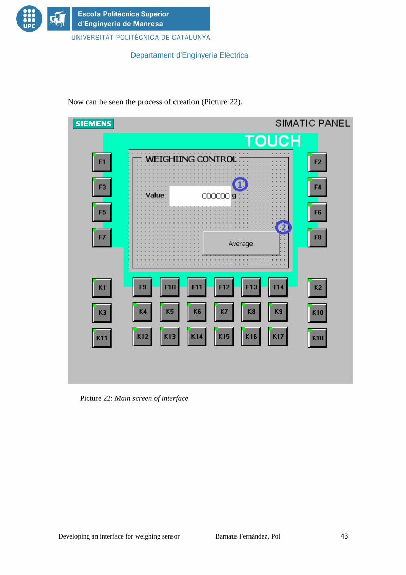
Now can be seen the process of creation (Picture 22).
Picture 22: Main screen of interface

Departament d’Enginyeria Elèctrica
Developing an interface for weighing sensor Barnaus Fernàndez, Pol 44
Picture 23: Operation screen of the interface

Departament d’Enginyeria Elèctrica
Developing an interface for weighing sensor Barnaus Fernàndez, Pol 45
The next table explains the development of the program.
NUMBER INTERFACE HOW IT WORKS
1 Number – box Output of the tag I_Gross_weight_CH1
2 Button Active screen “operation”, and set tag Active_comparation
3 Number – box Output of the tag I_Gross_eight_CH1
4 Button On press set tag Comp_adq1. On release reset the same tag.
5 Button On press set tag Comp_adq2. On release reset the same tag.
6 Number - box Output of the tag comp_value1
7 Number – box Output of the tag Comp_value2
8 Marker (output) Visible it the tag Comp_less is high
9 Marker (output) Visible if the tag Comp_equal is high
10 Marker (output) Visible if the tag Comp_greater is high
11 Number - box Output of the tag Average
12 Button Active screen “main screen”
Table 4: Explanation of the development interface

Departament d’Enginyeria Elèctrica
Developing an interface for weighing sensor Barnaus Fernàndez, Pol 46
7. CONCLUSIONS
This project has seen the value that have the plc in real life, especially work. In this
case, creating the weighing interface has been found necessary to do the simplest things
for a worker. With all the problems has had in time to use the SIMATIC S7, has been
seen as a program of great power and capacity to implement programs for the PLC.
If we look at the entire set for this project, it can be seen that the combination of all
programs and driver do you have a great power. First of all, with the Siemens S7-300
combined with SIWAREX U module, the realization of the hardware is much simply.
Second, thanks to the WinCC flexible 2008 software can perform a neat interface and
simple way so that you can see on the touch panel. If we combine SIMATIC S7 with
SIWATOOL U to make the correct tare and the interface have created a fairly simple
process with few steps and very useful.
In this project with the interface can be read the real weight, and all the results obtained
in practice were correct and the objective have been achieved successfully.

Departament d’Enginyeria Elèctrica
Developing an interface for weighing sensor Barnaus Fernàndez, Pol 47
8. BIBLIOGRAPHY
http://books.google.de/books?id=zsyTTGxCIdMC&pg=PA7&redir_esc=y#v=onepage&q&f
=false
http://www.automation.siemens.com/mcms/sensor-systems/en/weighing-systems/load-
cell/bending-beam-load-cells/Pages/siwarex-r-bb.aspx
http://support.automation.siemens.com/WW/llisapi.dll?func=cslib.csinfo&lang=en&objid=2
8392477&caller=view
http://usedplcs.co.uk/manuals/siemens/HMI/TP177B.pdf
http://w3.siemens.com/mcms/programmable-logic-controller/en/simatic-s7-controller/s7-
300/cpu/Pages/Default.aspx
9. ACKNOWLEDGMENTS
I acknowledge at first the Hochschule Mittweida - University of Applied Sciences, that
provided all support that I needed.
I acknowledge to EPSEM, UPC

Departament d’Enginyeria Elèctrica
Developing an interface for weighing sensor Barnaus Fernàndez, Pol 48
10. SIGNATURES
Pol Barnaus Fernàndez
INTERN
Josep Font Teixidor
MENTOR / EPSEM / SPAIN
Departament d’Enginyeria Elèctrica
Developing an interface for weighing sensor Barnaus Fernàndez, Pol 49
11. APPENDIX 11.1 LADDER FOR TRAFFIC LIGHTS SYSTEM
LEARNING MODULE
Departament d’Enginyeria Elèctrica
Developing an interface for weighing sensor Barnaus Fernàndez, Pol 50

Departament d’Enginyeria Elèctrica
Developing an interface for weighing sensor Barnaus Fernàndez, Pol 51
Departament d’Enginyeria Elèctrica
Developing an interface for weighing sensor Barnaus Fernàndez, Pol 52
11.2 WEIGHING BLOCKS IN SIMATIC S7
Departament d’Enginyeria Elèctrica
Developing an interface for weighing sensor Barnaus Fernàndez, Pol 53

Departament d’Enginyeria Elèctrica
Developing an interface for weighing sensor Barnaus Fernàndez, Pol 54

Departament d’Enginyeria Elèctrica
Developing an interface for weighing sensor Barnaus Fernàndez, Pol 55