Embed Size (px)
Citation preview
Paper ID #34295
Developing and Teaching Modular Robots
Dr. Arif Sirinterlikci, Robert Morris University
Arif Sirinterlikci is a University Professor of Industrial and Manufacturing Engineering at Robert MorrisUniversity (RMU). He also serves as the Senior Director of the RMU Outreach and Innovation Center.He holds BS and MS degrees, both in Mechanical Engineering from Istanbul Technical University inTurkey and his Ph.D. is in Industrial and Systems Engineering from the Ohio State University. He isalso a Certified Manufacturing Engineer (CMfgE). He has been actively involved in ASEE and SMEorganizations and conducted research in Rapid Prototyping and Reverse Engineering, Biomedical DeviceDesign and Manufacturing, Automation and Robotics, and CAE in Manufacturing Processes fields.
c©American Society for Engineering Education, 2021
Developing and Teaching Modular Robots
Abstract
This study focuses on development and teaching modular industrial robots to students from a
variety of levels including high school and college. Initially, MOSS modular robotics system, a
robotic toy, was chosen as the development platform. However, it was not found to be adequate
for most of the industrial robot configurations, excluding the articulated robot arm. Thus,
additional components were designed by two engineering students and made to be interfaced
with the existing MOSS modules to accomplish configurations like selectively compliant
articulated robot arm (SCARA) and cylindrical robots. The newly developed robot
configurations are programmed through C programming language within the Visual Studio
coding environment. MOSS robotics system was utilized due to its user-configurable modular
robotic structure giving an additional dimension to the learning experience since it is a true
modular robotic system. After the initial development work, a high-school workshop was
conducted in collaboration with a neighboring school district led by the two engineering students
who designed the modifications. The current development efforts include design of an Arduino-
based modular structure and possible use of self-configuration. This paper includes the detailed
sketch of the development efforts, engineering students’ reflections on the development project,
design and delivery of the high school workshop including high school student feedback, and
possible future college level curricular designs for modular industrial robotics for industrial,
mechanical, and manufacturing engineering programs. The paper is concluded with future work
concepts including possible kinematics and dynamics modeling of these industrial robot
configurations through simulation tools such as DELMIA or MapleSIM, along with use of
machine learning for self-configuration.
Background
The modular robot is a fairly new type employed to extend the utilization of robots into
additional areas. The history of modular robots starts in 1972 when the active chain chord
mechanism (ACM) was developed, leading to future development of chain-type modular robots.
[1] The modular robot research started to gain momentum in the late 1980s, followed by the
development of Cellular Robotic System (CEBOT), which was characterized by self-
organization, self-evaluation and functional amplification where multiple modules collaborated
to accomplish the task. [2]
Modular robots are mostly reconfigurable and thus more adaptable. There a two distinct types:
user-configurable and self-configuring:
User-configurable robots are configured by their operators to perform desired tasks. The
users modify the physical and functional configuration by adjusting their hardware and
software components, becoming a part of the robot’s behavior.[3] Each module (i.e.
power supply, processor, sensor, or actuator) has mechanisms for connecting to other
modules and comes with its own electronics. Modular robot behavior relies on such
aspects as size and abstraction levels of the modules (granularity), connectivity and
interaction of the modules, ease of construction, algorithms that control autonomy, and
mobility patterns. [3][4] Affordance or invitation to the user along with transparency of
the functionality of the modules are also critical for the user-configurable types. [3]
The concept of self-configuring robots is self-explanatory. Self-configuring modular
robots are further adaptable when compared to their user-configurable counterparts since
they use morphing algorithms. [5][6][7] A fairly recently developed self-configured
modular robot employs adaptive locomotion with Bluetooth technology built into each
module. [8]
This project was originally envisioned as a reverse engineering effort focusing on two
commercially available modular robotic toys, Cubelets and MOSS from Modular Robotics. After
learning about their structure and detail designs, the focus was shifted to utilizing MOSS
modules in teaching industrial robot configurations (i.e. articulated robots including Selectively
Compliant Articulated Robot Arm (SCARA) manipulators) at high school and college levels.
MOSS was selected due to its greater flexibility including availability of larger number of
module types. During the process of developing industrial configurations, the team realized that
the current MOSS modules could not support construction of some of the industrial robot
configurations without re-engineering. Additional components had to be designed and built by
3D printing for enhancing functionality of standard MOSS modules .
As the team studied the structures of MOSS components, a comprehensive literature review on
modular robotics was carried out and a large amount of research was found on the subject
including reconfigurable modular robots [9]. A second literature review was focused on
utilization of modular robots in education. The results of the second study yielded a small
number of literature, which encouraged the project team to continue their work. The four most
relevant papers found in the literature review are summarized below. Only a pair of the four
papers found are directly related to the objective of this paper, while the other two are based on a
modular building block system in developing robots or machines; the system they are based is
not a true modular robotic system, even though it is user-configurable. It is similar to LEGOs.
Nielsen and Lund developed I-BLOCKS, a modular robotic system for use as an educational
tool.[10] They evaluated their designs at schools and hospitals and in multiple countries with the
goal of recommending improvements to their designs. However, their study did not center on
teaching industrial robotics through modular robotics. In another study by Correll et al.[11],
computer scientists from the University of Colorado at Boulder used Cubelets modular robot
construction kit to teach middle school students computer science. The work focused not on
modular robots, but on quickly preparing and delivering a short robotics session to middle school
students. Hsieh [12], from Texas A & M University, has been teaching reconfigurable and
scalable systems projects as a part of the industrial automation and controls curriculum while
applying a comprehensive approach that addresses multiple learning styles and integrates
knowledge and skills. The most intriguing part of Hsieh’s research is not the project based
approach but the tool he used to teach reconfigurable and scalable systems. Fischertechnik is a
modular construction system similar to LEGOs that can be used in building and simulating
industrial robotic work-cells and machines, including industrial and mobile robots, as well as
punching machines, indexing lines, pneumatic processing centers, and automated warehouses. In
another effort, Xiao et al. [13] also used the Fischertechnik system to cultivate mechanical
innovation through projects after teaching the basic knowledge behind creativity, innovation, and
ideation. Student works built with the modular blocks were submitted to the National
Undergraduate Mechanical Innovation Design Competition in China and included industrial
machines such as machining centers or rubbish cleaning machines.
The MOSS System
The objective of the MOSS system is “to impart intuitive understanding of complex systems and
design principles” according to its maker – Modular Robotics. [14][15][16] Children are exposed
to “mechanical construction, basic circuitry, kinematic motion, robotics, software integration,
and programming” through modular robot design and construction. [17] It is an interesting tool
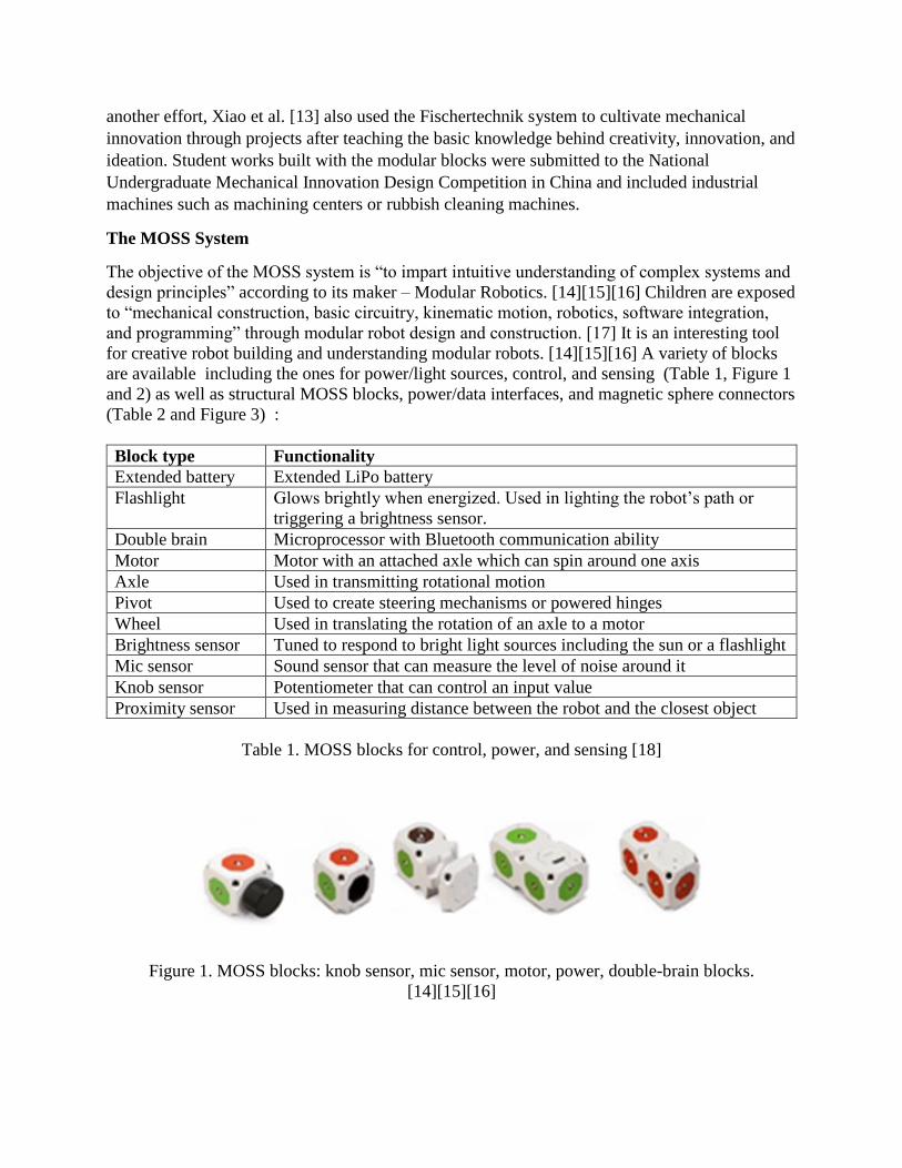
for creative robot building and understanding modular robots. [14][15][16] A variety of blocks
are available including the ones for power/light sources, control, and sensing (Table 1, Figure 1
and 2) as well as structural MOSS blocks, power/data interfaces, and magnetic sphere connectors
(Table 2 and Figure 3) :
Block type Functionality
Extended battery Extended LiPo battery
Flashlight Glows brightly when energized. Used in lighting the robot’s path or
triggering a brightness sensor.
Double brain Microprocessor with Bluetooth communication ability
Motor Motor with an attached axle which can spin around one axis
Axle Used in transmitting rotational motion
Pivot Used to create steering mechanisms or powered hinges
Wheel Used in translating the rotation of an axle to a motor
Brightness sensor Tuned to respond to bright light sources including the sun or a flashlight
Mic sensor Sound sensor that can measure the level of noise around it
Knob sensor Potentiometer that can control an input value
Proximity sensor Used in measuring distance between the robot and the closest object
Table 1. MOSS blocks for control, power, and sensing [18]
Figure 1. MOSS blocks: knob sensor, mic sensor, motor, power, double-brain blocks.
[14][15][16]
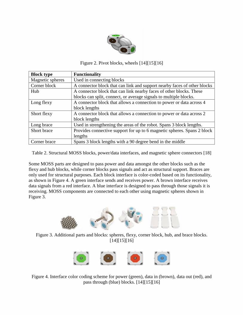
Figure 2. Pivot blocks, wheels [14][15][16]
Block type Functionality
Magnetic spheres Used in connecting blocks
Corner block A connector block that can link and support nearby faces of other blocks
Hub A connector block that can link nearby faces of other blocks. These
blocks can split, connect, or average signals to multiple blocks.
Long flexy A connector block that allows a connection to power or data across 4
block lengths
Short flexy A connector block that allows a connection to power or data across 2
block lengths
Long brace Used in strengthening the areas of the robot. Spans 3 block lengths.
Short brace Provides connective support for up to 6 magnetic spheres. Spans 2 block
lengths
Corner brace Spans 3 block lengths with a 90 degree bend in the middle
Table 2. Structural MOSS blocks, power/data interfaces, and magnetic sphere connectors [18]
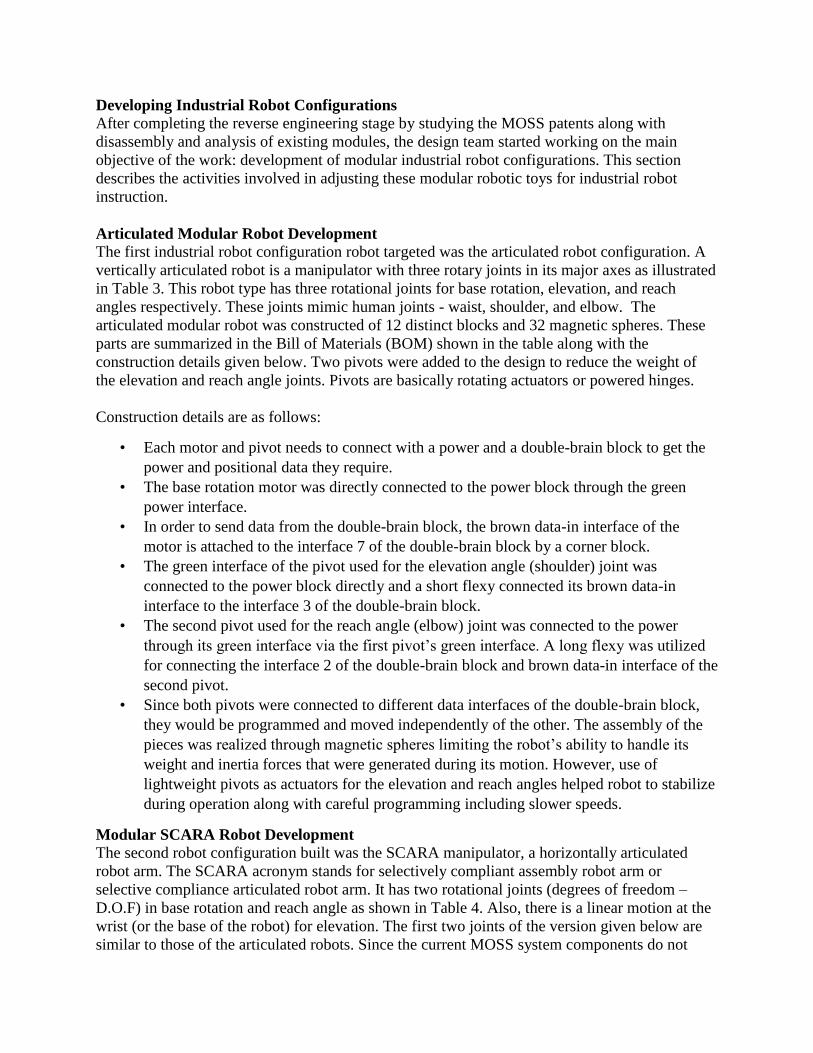
Some MOSS parts are designed to pass power and data amongst the other blocks such as the
flexy and hub blocks, while corner blocks pass signals and act as structural support. Braces are
only used for structural purposes. Each block interface is color-coded based on its functionality,
as shown in Figure 4. A green interface sends and receives power. A brown interface receives
data signals from a red interface. A blue interface is designed to pass through those signals it is
receiving. MOSS components are connected to each other using magnetic spheres shown in
Figure 3.
Figure 3. Additional parts and blocks: spheres, flexy, corner block, hub, and brace blocks.
[14][15][16]
Figure 4. Interface color coding scheme for power (green), data in (brown), data out (red), and
pass through (blue) blocks. [14][15][16]
Developing Industrial Robot Configurations After completing the reverse engineering stage by studying the MOSS patents along with
disassembly and analysis of existing modules, the design team started working on the main
objective of the work: development of modular industrial robot configurations. This section
describes the activities involved in adjusting these modular robotic toys for industrial robot
instruction.
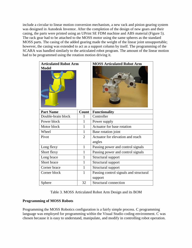
Articulated Modular Robot Development The first industrial robot configuration robot targeted was the articulated robot configuration. A
vertically articulated robot is a manipulator with three rotary joints in its major axes as illustrated
in Table 3. This robot type has three rotational joints for base rotation, elevation, and reach
angles respectively. These joints mimic human joints - waist, shoulder, and elbow. The
articulated modular robot was constructed of 12 distinct blocks and 32 magnetic spheres. These
parts are summarized in the Bill of Materials (BOM) shown in the table along with the
construction details given below. Two pivots were added to the design to reduce the weight of
the elevation and reach angle joints. Pivots are basically rotating actuators or powered hinges.
Construction details are as follows:
• Each motor and pivot needs to connect with a power and a double-brain block to get the
power and positional data they require.
• The base rotation motor was directly connected to the power block through the green
power interface.
• In order to send data from the double-brain block, the brown data-in interface of the
motor is attached to the interface 7 of the double-brain block by a corner block.
• The green interface of the pivot used for the elevation angle (shoulder) joint was
connected to the power block directly and a short flexy connected its brown data-in
interface to the interface 3 of the double-brain block.
• The second pivot used for the reach angle (elbow) joint was connected to the power
through its green interface via the first pivot’s green interface. A long flexy was utilized
for connecting the interface 2 of the double-brain block and brown data-in interface of the
second pivot.
• Since both pivots were connected to different data interfaces of the double-brain block,
they would be programmed and moved independently of the other. The assembly of the
pieces was realized through magnetic spheres limiting the robot’s ability to handle its
weight and inertia forces that were generated during its motion. However, use of
lightweight pivots as actuators for the elevation and reach angles helped robot to stabilize
during operation along with careful programming including slower speeds.
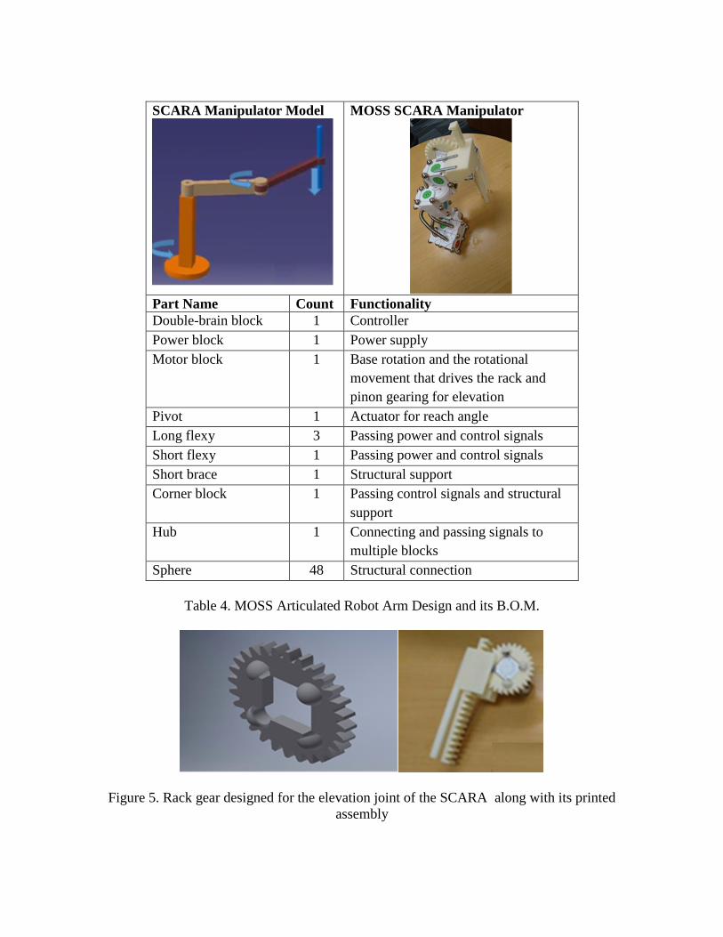
Modular SCARA Robot Development
The second robot configuration built was the SCARA manipulator, a horizontally articulated
robot arm. The SCARA acronym stands for selectively compliant assembly robot arm or
selective compliance articulated robot arm. It has two rotational joints (degrees of freedom –
D.O.F) in base rotation and reach angle as shown in Table 4. Also, there is a linear motion at the
wrist (or the base of the robot) for elevation. The first two joints of the version given below are
similar to those of the articulated robots. Since the current MOSS system components do not
include a circular to linear motion conversion mechanism, a new rack and pinion gearing system
was designed in Autodesk Inventor. After the completion of the design of new gears and their
casing, the parts were printed using an UPrint SE FDM machine and ABS material (Figure 5).
The rack gear had to be attached to the MOSS motor using the same spheres as the standard
MOSS parts. The casing of the added gearing made the weight of the linear joint unsupportable;
however, the casing was extended to act as a support column by itself. The programming of the
SCARA was handled similarly to the articulated robot program. The amount of the linear motion
had to be programmed using the rotation motion driving it.
Articulated Robot Arm
Model
MOSS Articulated Robot Arm
Part Name Count Functionality
Double-brain block 1 Controller
Power block 1 Power supply
Motor block 1 Actuator for base rotation
Wheel 1 Base rotation joint
Pivot 2 Actuator for elevation and reach
angles
Long flexy 1 Passing power and control signals
Short flexy 1 Passing power and control signals
Long brace 1 Structural support
Short brace 1 Structural support
Corner brace 1 Structural support
Corner block 1 Passing control signals and structural
support
Sphere 32 Structural connection
Table 3. MOSS Articulated Robot Arm Design and its BOM
Programming of MOSS Robots
Programming the MOSS Robotics configuration is a fairly simple process. C programming
language was employed for programming within the Visual Studio coding environment. C was
chosen because it is easy to understand, manipulate, and modify in controlling robot operation.
SCARA Manipulator Model
MOSS SCARA Manipulator
Part Name Count Functionality
Double-brain block 1 Controller
Power block 1 Power supply
Motor block 1 Base rotation and the rotational
movement that drives the rack and
pinon gearing for elevation
Pivot 1 Actuator for reach angle
Long flexy 3 Passing power and control signals
Short flexy 1 Passing power and control signals
Short brace 1 Structural support
Corner block 1 Passing control signals and structural
support
Hub 1 Connecting and passing signals to
multiple blocks
Sphere 48 Structural connection
Table 4. MOSS Articulated Robot Arm Design and its B.O.M.
Figure 5. Rack gear designed for the elevation joint of the SCARA along with its printed
assembly
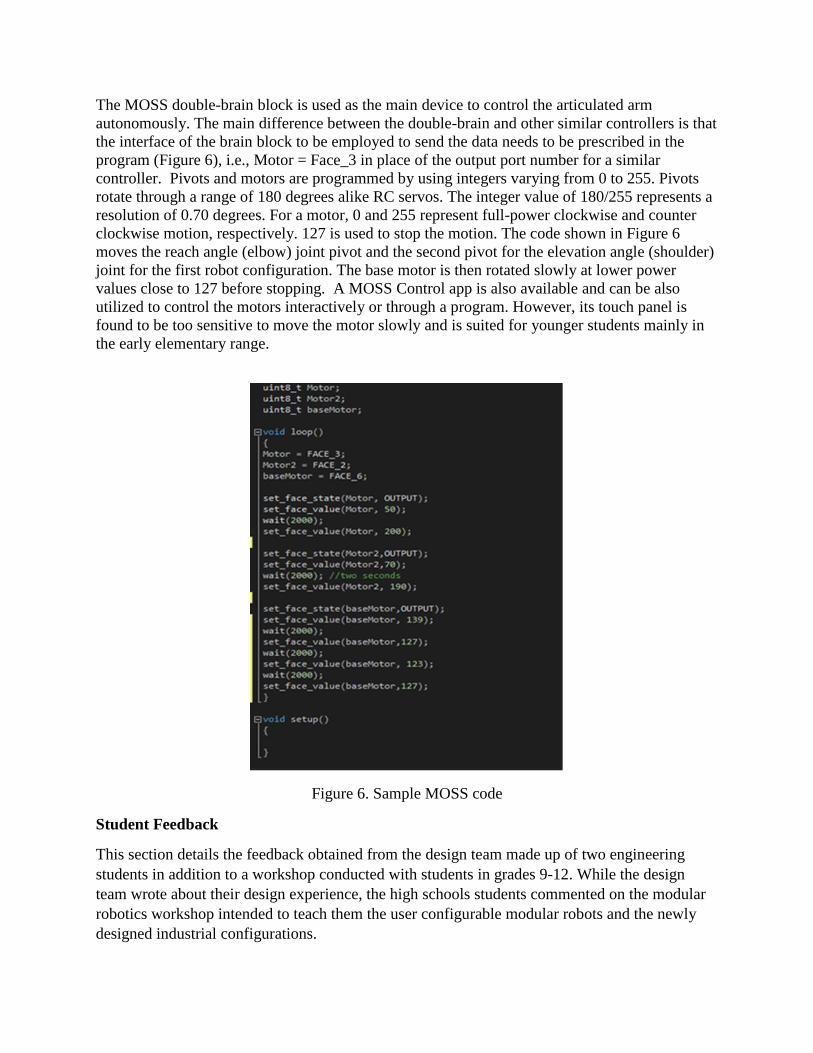
The MOSS double-brain block is used as the main device to control the articulated arm
autonomously. The main difference between the double-brain and other similar controllers is that
the interface of the brain block to be employed to send the data needs to be prescribed in the
program (Figure 6), i.e., Motor = Face_3 in place of the output port number for a similar
controller. Pivots and motors are programmed by using integers varying from 0 to 255. Pivots
rotate through a range of 180 degrees alike RC servos. The integer value of 180/255 represents a
resolution of 0.70 degrees. For a motor, 0 and 255 represent full-power clockwise and counter
clockwise motion, respectively. 127 is used to stop the motion. The code shown in Figure 6
moves the reach angle (elbow) joint pivot and the second pivot for the elevation angle (shoulder)
joint for the first robot configuration. The base motor is then rotated slowly at lower power
values close to 127 before stopping. A MOSS Control app is also available and can be also
utilized to control the motors interactively or through a program. However, its touch panel is
found to be too sensitive to move the motor slowly and is suited for younger students mainly in
the early elementary range.
Figure 6. Sample MOSS code
Student Feedback
This section details the feedback obtained from the design team made up of two engineering
students in addition to a workshop conducted with students in grades 9-12. While the design
team wrote about their design experience, the high schools students commented on the modular
robotics workshop intended to teach them the user configurable modular robots and the newly
designed industrial configurations.
Reflections from the Design Team
The team members reflected about two different parts of their design experience: what they
learned and what they could have done differently. Summary of the statements given below
pointing out two complex problem solving activities and creativity in a real-life like situation in
which they had to design industrial robot configurations based on MOSS modular robotics
components.
• Team Member #1: Throughout the project, I have learned plenty of skills. Some skills
that I strengthened during this project were problem solving, designing of new parts, and
integrating creative ideas to simulate something in the real world. Problem solving skills
are essential to everyday life and especially in the field of engineering. These skills
within this project showed through the process of designing the modular pieces to
become something truly relevant in the real world and it proved to be difficult at some
times. Throughout my high school and college career, I’ve loved designing new parts by
using applications such as SolidWorks and Autodesk Inventor. By designing the new
parts such as spur gears, rack gears, and other components to easily combine blocks, my
design skills have become more useful and I’ve learned much more about the
applications themselves. Simulating the real world applications of different industrial
robots, the creativeness of this project has sufficiently helped me understand that it is
very important to simulate something before making it a reality.
Some things that I would have done differently are re-engineering the MOSS blocks
themselves to create more sophisticated pieces and spend more time thinking of better
ways to recreate the robots. Some problems we came across while completing this project
were that some pieces were too small and many times the blocks became too top heavy
and would ruin the integrity when the motors and blocks would move. Therefore, re-
engineering these blocks to what would have been a great help in the process.
Overall this project was helpful in learning new processes, thinking outside of the box,
and problem solving. I had a great experience completing this project and have future
plans to make the modular pieces self-configuring with sensors and other new
technology.
• Team Member #2: This project was very helpful for learning how industrial robots work.
At the beginning, I spent time doing research about industrial robots which were
SCARA, articulated, spherical, cylindrical, Cartesian, and parallel robot type. Each robot
has a different joint configuration and features. MOSS, a robot toy from Modular
Robotics, was a useful tool in designing small industrial robots for an educational
purpose. I learned how the toy worked and how the components could be applied to
create small industrial robots. Most of the robots’ joint configurations can be driven by
the motor and pivot blocks. However, some robots could not be built only by the MOSS
parts. Thus, 3D printing played an important role in this project. During the process of
designing and printing new parts process, I learned how to reengineer using trial and
error, over and over again. For example, when 3D printed parts were too heavy to embed
into the robot, I made another one which was less heavy by printing hollow blocks or
making holes while keeping their function. Programming was also a large task in this
project. The MOSS program is based on the C language code. I gained a good knowledge
about the programming language. In addition, understanding how the code worked was a
difficult process. The robot needed to move like an actual industrial robot. Likewise, in
the designing process, there were many times trial and error was used in the
programming process. I developed engineering skills through the project. I learned each
industrial robot’s characteristics and how to design new parts.
If I were to do this project again, I would probably have done it following a simpler
design. I spent a lot of time designing and printing new parts because I was not familiar
with design software and 3D printer. Furthermore, choosing some prototypes was taking
plenty of time while figuring out how to build the robots. The design process had also
time constraints. Thus, I would think more straightforward and complete more industrial
robot designs in the project next time although I enjoyed learning from complicated tasks
that I did in the project.
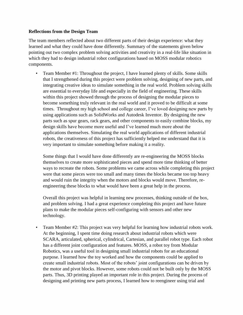
High School Modular Robotics Workshop
Nine high-school students from Moon Area High School located in suburban Pittsburgh,
Pennslyvania participated in a four-hour workshop on modular robotics based on the newly
designed configurations. The group was composed of three 12th graders, three 11th graders, one
10th grader, and two 9th graders. The participants were asked to complete a pre-workshop
survey gauging their understanding of robots including modular and industrial robots as well as
computer programming. A description of modular robots including user and auto configuring
types was also given to the participants along with the pre-workshop survey. A summary of the
survey results is presented below in the following table – Table 5. Pre-workshop survey
indicated (through questions 1, 2, and 3) that the participants have had some exposure to
educational robotics, construction toys, and computer programming as expected. However, none
of the 9 participants were exposed to modular robotics and industrial environments.
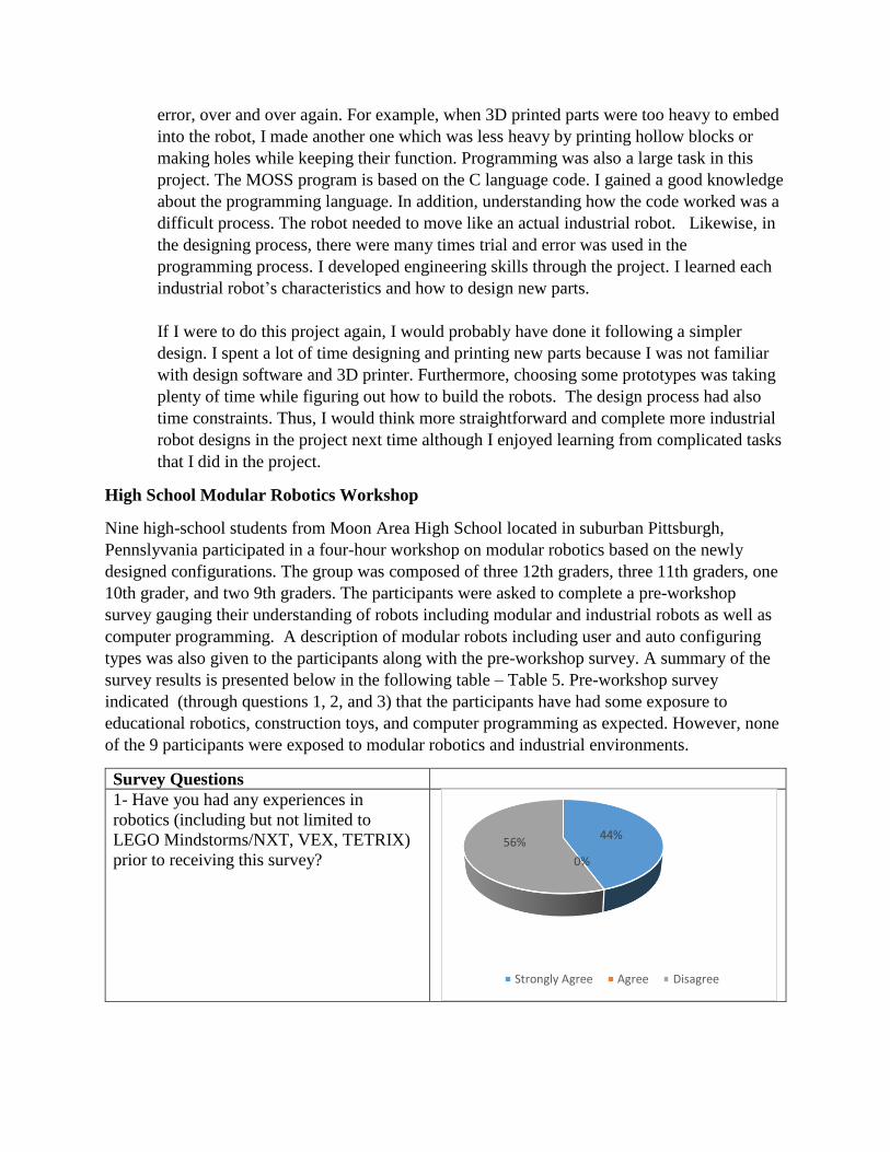
Survey Questions
1- Have you had any experiences in
robotics (including but not limited to
LEGO Mindstorms/NXT, VEX, TETRIX)
prior to receiving this survey?
44%
0%
56%
Strongly Agree Agree Disagree
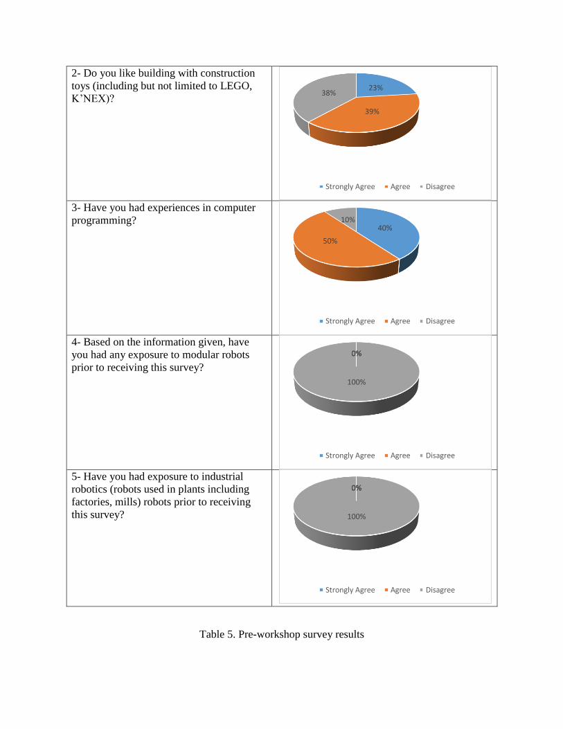
2- Do you like building with construction
toys (including but not limited to LEGO,
K’NEX)?
3- Have you had experiences in computer
programming?
4- Based on the information given, have
you had any exposure to modular robots
prior to receiving this survey?
5- Have you had exposure to industrial
robotics (robots used in plants including
factories, mills) robots prior to receiving
this survey?
Table 5. Pre-workshop survey results
23%
39%
38%
Strongly Agree Agree Disagree
40%
50%
10%
Strongly Agree Agree Disagree
0%0%
100%
Strongly Agree Agree Disagree
0%0%
100%
Strongly Agree Agree Disagree
After a combination of short presentations (on MOSS modular robots, industrial robot
configurations available in house) and building and programming activities of MOSS industrial
robot configurations, students were given a post survey that included two questions. The first
question was intended to see how the students perceived the workshop’s value. The second
question was used to gauge their understanding of the modular robots in a deeper way, since all
of the participants demonstrated good understanding of both modular and industrial robot basics,
along with good programming skills. Tables 6 and 7 document the responses of the participants.
The post survey indicated that the students were kept engaged while learning about the modular
robots and the newly designed industrial robot configurations. They positively responded to the
hands-on activities including problem solving for modifying modular robot configurations,
programming of the new configurations, and free time where they built additional modular robot
designs of their own.
Participant Responses
The lesson of how real business and industries use modular robots in everyday use
Learning the different ways to problem solve
Hands-on activities with building the modular robots
Getting to talk to college students and learn about the aspects of modular robots in a working
situation
I really liked the free time at the end of the workshop where we were allowed to do whatever
we wanted with the modular robots.
I found that the most useful for me was actually working with the modular robots, hand-on.
That includes constructing and programming the robots in our groups. I feel that it is difficult
to learn about them without actually seeing what is behind the scenes and doing it for yourself.
Table 6. Post Survey Question 1: What Aspects of this Workshop Were Most Useful or
Valuable?
Participant Responses
They are easy to use and can be used for many different things.
I think it is a great idea. Applications that can benefit from modular robotics are hospitals and
assembly lines.
Modular robots have a wide variety of applications and uses in industry. They can be integrated
in the wider society, although this would likely be difficult. More menial jobs might be able
to be taken over by modular robotics, and this would allow people to produce products of
higher quality and quantity.
Very useful in industry; all applications can benefit especially those that need (likely) more
inexpensive robots with specific function as modular robots are able do a variety tasks
depending on how they are arranged.
They could improve manufacturing and potentially be used in medical situations.
I think that it is a good idea as long as they are able to stay together. They could be used for
natural disasters or in the medical field.
I feel that modular robotics can be useful in industry. With the right toolset of modular robots
one could easily configure robots when needed based on the application. Also, one could build
a robot for one job and then quickly disassemble and reassemble another robot for a different
task using the same materials. The biggest benefit would be the ease of maneuverability and
the ability to quickly change the robots for different tasks.
Table 7. Post Survey Question 2: What is Your Opinion about Modular Robots Being in
Industry? What Applications Can Benefit from Modular Robotics?
Student feedback presented in Table 7 indicates that students envisioned possible applications in
industrial and medical needs along with natural disaster help, with expansion to wider use into
other fields. Multiple students commented on modular robots being flexible and adaptable, and
thus efficient for handling a variety of applications with quick changeover, both in configurations
and tooling. The author has been satisfied with student performance and feedback in this first
outreach effort. The main negative comment received was due to magnetic spheres, as
participants experienced occasional failure to keep the modules together.
Arduino Based Modular Robot Concept
After the completion of the first phase presented above including work on cylindrical and
spherical (polar) configurations, the design team shifted its focus to use of MOSS modular robots
in developing self-configuring applications. The concept was based on a basic robot design with
multiple modules including controls, mobility with motor modules, and sensing ability to be
responding to its environment. Based on the feedback from its environment, the logic envisioned
was to channel the robot to build itself differently. This concept since then has been modified to
include Arduino based own modules and the exploration of machine learning to be added to the
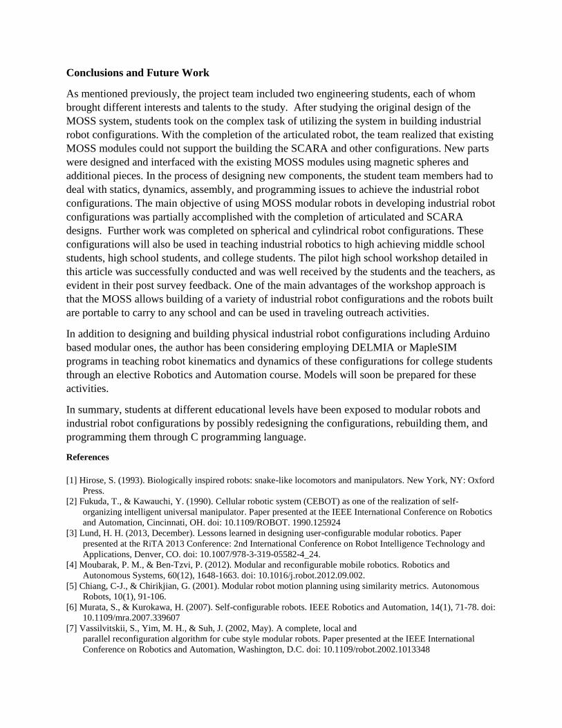
work. Limited information is presented in this paper, since this propriety work is still in progress.
The base module design is shown in Figure 7 while the hollow hexagon patterns represent the
modules to be attached.
Figure 7. Arduino-based modular robot concept with its base module
Sensor
Actuator
Arduino Microcontroller
Conclusions and Future Work
As mentioned previously, the project team included two engineering students, each of whom
brought different interests and talents to the study. After studying the original design of the
MOSS system, students took on the complex task of utilizing the system in building industrial
robot configurations. With the completion of the articulated robot, the team realized that existing
MOSS modules could not support the building the SCARA and other configurations. New parts
were designed and interfaced with the existing MOSS modules using magnetic spheres and
additional pieces. In the process of designing new components, the student team members had to
deal with statics, dynamics, assembly, and programming issues to achieve the industrial robot
configurations. The main objective of using MOSS modular robots in developing industrial robot
configurations was partially accomplished with the completion of articulated and SCARA
designs. Further work was completed on spherical and cylindrical robot configurations. These
configurations will also be used in teaching industrial robotics to high achieving middle school
students, high school students, and college students. The pilot high school workshop detailed in
this article was successfully conducted and was well received by the students and the teachers, as
evident in their post survey feedback. One of the main advantages of the workshop approach is
that the MOSS allows building of a variety of industrial robot configurations and the robots built
are portable to carry to any school and can be used in traveling outreach activities.
In addition to designing and building physical industrial robot configurations including Arduino
based modular ones, the author has been considering employing DELMIA or MapleSIM
programs in teaching robot kinematics and dynamics of these configurations for college students
through an elective Robotics and Automation course. Models will soon be prepared for these
activities.
In summary, students at different educational levels have been exposed to modular robots and
industrial robot configurations by possibly redesigning the configurations, rebuilding them, and
programming them through C programming language.
References
[1] Hirose, S. (1993). Biologically inspired robots: snake-like locomotors and manipulators. New York, NY: Oxford
Press.
[2] Fukuda, T., & Kawauchi, Y. (1990). Cellular robotic system (CEBOT) as one of the realization of self-
organizing intelligent universal manipulator. Paper presented at the IEEE International Conference on Robotics
and Automation, Cincinnati, OH. doi: 10.1109/ROBOT. 1990.125924
[3] Lund, H. H. (2013, December). Lessons learned in designing user-configurable modular robotics. Paper
presented at the RiTA 2013 Conference: 2nd International Conference on Robot Intelligence Technology and
Applications, Denver, CO. doi: 10.1007/978-3-319-05582-4_24.
[4] Moubarak, P. M., & Ben-Tzvi, P. (2012). Modular and reconfigurable mobile robotics. Robotics and
Autonomous Systems, 60(12), 1648-1663. doi: 10.1016/j.robot.2012.09.002.
[5] Chiang, C-J., & Chirikjian, G. (2001). Modular robot motion planning using similarity metrics. Autonomous
Robots, 10(1), 91-106.
[6] Murata, S., & Kurokawa, H. (2007). Self-configurable robots. IEEE Robotics and Automation, 14(1), 71-78. doi:
10.1109/mra.2007.339607
[7] Vassilvitskii, S., Yim, M. H., & Suh, J. (2002, May). A complete, local and
parallel reconfiguration algorithm for cube style modular robots. Paper presented at the IEEE International
Conference on Robotics and Automation, Washington, D.C. doi: 10.1109/robot.2002.1013348
[8] Moeckel, R., Jaquier, C., Drapel, K., Dittrich, E., Upegui, A., Auke, & Ljspeert, A. J,(2006). Exploring
Locomotion with YaMoR, a novel autonomous modular robot with Bluetooth interface. Industrial Robot, 33(4),
285-290. doi: 10.1108/ 01439910610667908
[9] Brunete, A., Ranganath, A., Segovia, S., Perez de Frutos, J., Hernando, M., & Gambao, E. (2017). Current trends
in reconfigurable modular robots design. International Journal of
Advanced Robotic Systems, 14(3). doi: 10.1177/1729881417710457
[10] Nielsen, J., & Lund H. H. (2008). Modular robotics as a tool for education and entertainment. Computers in
Human Behavior, 24(2), 234-248.
[11] Correll, N., Wailes, C., & Slaby, S. (2012, November). A one-hour curriculum to engage middle school
students in robotics and computer science using Cubelets. Paper presented at the 11th International Symposium
on Distributed Autonomous Robotic Systems (DARS), Baltimore, MD. doi: 10.1007/978-3-642-55146-8_12.
[12] Hsieh, S.-J. (2011, June). Reconfigurable and scalable automated systems projects for manufacturing
automation and control education. Paper presented at the 118th ASEE Annual Conference and Exposition,
Vancouver, BC.
[13] Xiao, X., Li, Z., & Yin, G. (2015). Cultivation of the ability of innovative practice through mechanical
innovation design. International Journal of Mechanical Engineering Education, 43(1), 38-43. doi:10.1177/
0306419015581736.
[14] Moss modular robotics. (2012a). Moss individual blocks. Retrieved from http://www.modrobotics.com/moss/.
[15] Moss modular robotics. (2012b). Getting started with Moss. Retrieved from
http://www.modrobotics.com/moss/moss-getting-started/.
[16] Moss modular robotics. (2012c). Pivot. Retrieved from http://www.modrobotics. com/moss/modules/pivot/.
[17] Amazon. (2017). Zombonitron package. Retrieved from https://www.amazon. com/Modular-Robotics-MOSS-
Zombonitron-1600/dp/B00JKLYNPI.
[18] Moss Exofabulatronixx 5200, Guide to Getting Started Modular Robotics.