Embed Size (px)
Citation preview
1
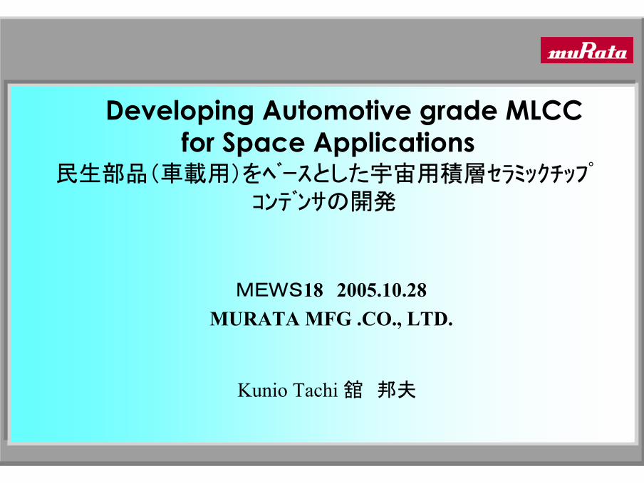
Developing Automotive grade MLCCfor Space Applications
民生部品(車載用)をベースとした宇宙用積層セラミックチップコンデンサの開発
MEWS18 2005.10.28MURATA MFG .CO., LTD.
Kunio Tachi 舘 邦夫
2
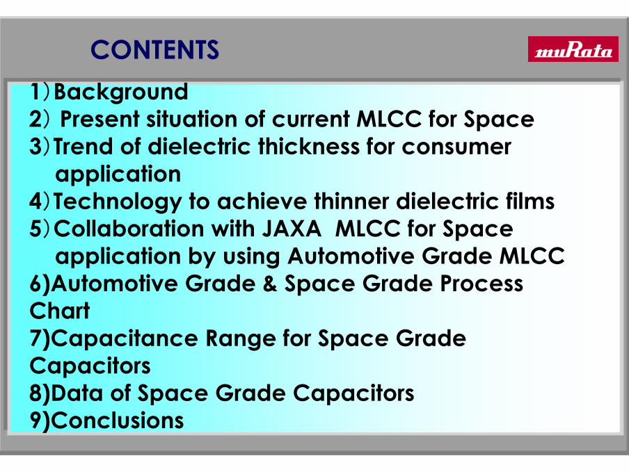
1)Background2) Present situation of current MLCC for Space3)Trend of dielectric thickness for consumer
application4)Technology to achieve thinner dielectric films5)Collaboration with JAXA MLCC for Space
application by using Automotive Grade MLCC6)Automotive Grade & Space Grade Process Chart7)Capacitance Range for Space Grade Capacitors8)Data of Space Grade Capacitors9)Conclusions
CONTENTS

3
1)Current MLCC(Multi-Layer Ceramic Capacitors) for Space application are
designed by using special material (ceramic/electrode/resin ) and design
rule . So, it is very difficult to cost reduction and also becomes difficult to get special material (ceramic/electrode/resin ).
2)And, order intake of MLCC for Space has been decreased. But it needs stability of supply, and Pb free.
3)We(MURATA’)shipment history to the automotive market for the past 2 years has been slightly over 20 billion pcs a year. The field failure rate of capacitors shipped to automotive customers was 1.2ppb.
4)JAXA and MURATA have joined hands in developing MLCC for spaceapplications based on existing automotive grade capacitors.
Background
4
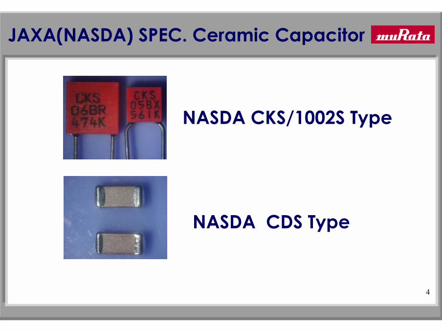
NASDA CDS Type
NASDA CKS/1002S Type
JAXA(NASDA) SPEC. Ceramic Capacitor

5
0
20
40
60
80
100
120
140
16095F1
95F2
96F1
96F2
97F1
97F2
98F1
98F2
99F1
99F2
00F1
00F2
01F1
01F2
02F1
02F2
03F1
03F2
04F1
04F2
05F1
<Kpcs/half year>
CKS/1002S(RK-R) CDS(GRH-R/GR-R)
Sales Trend of Capacitor for Space application
6
1. Trend of dielectric thickness for consumer applications

7
0.1
1
10
100
1980 1985 1990 1995 2000 2005 2010
year
Die
lect
ric
Thi
ckne
ss (
µm )
Trend of dielectric thickness Trend of dielectric thickness (for consumer applications)(for consumer applications)
0603 Size-10uF-6.3V(1μm)
0805 Size-10uF6.3V(1.7μm)
1206 Size-10uF-25V(3μm)
1206 Size-1uF-16V(9μm)
8
0.1
1
10
1980 1985 1990 1995 2000 2005 2010
year
Rat
ed V
olta
ge (V
/µm
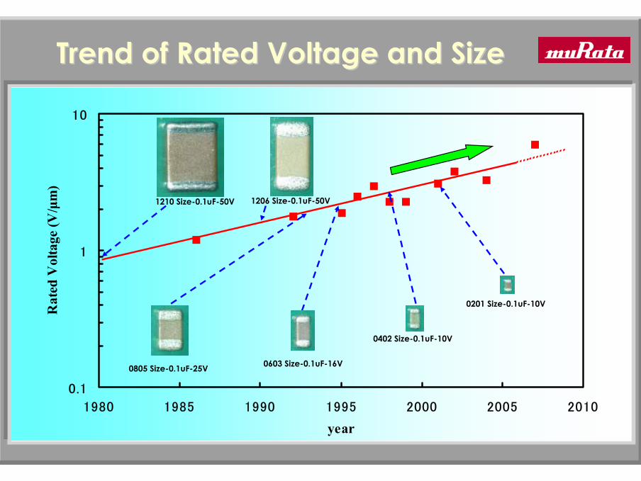
)Trend of Rated Voltage and Size Trend of Rated Voltage and Size
0805 Size-0.1uF-25V 0603 Size-0.1uF-16V
0402 Size-0.1uF-10V
1206 Size-0.1uF-50V
0201 Size-0.1uF-10V
1210 Size-0.1uF-50V
9
2. Technology to achieve thinner dielectric films

10
Low withstanding voltage,shorter life, poor reliability, etc.
Unevenness of inner electrode
Pore
Areas of non-uniform composition
Technologies to achieve thinner dielectric;Mainly 1)Fine ceramic powder
2)High density of green film3)Uniformity of Composition 4)Thin and smooth electrode
Technology to achieve thinner dielectric filmsTechnology to achieve thinner dielectric films
Similar technology would lead to
New technology
Inner electrode
Dielectric layer

11
Cross section of 0603 Size X5R 10uF 6.3V
Internal Structure of MLCCInternal Structure of MLCC with latestwith latest TechnologyTechnology
FE-SEM Picture
Number of Dielectric layers:320
Inner electrode :Ni
Fine and uniform grains
Thin and dense dielectric layer
Thin and smooth electrode
500um

Schematic of a Multi Layer Ceramic CapacitorSchematic of a Multi Layer Ceramic Capacitor
Precious Metals Electrode Products Base Metals Electrode Products
Pd or Ag/Pd Ni
1st layer Ag/Pd or Ag Cu (or Ag/Pd)2nd layer Ni Ni3rd layer Sn Sn
Inner electodeTermination
Inner electrode
Termination
1st layer2nd layer3rd layer

13
3. Collaboration with JAXA MLCC for Space Application by using Automotive Grade MLCC
14
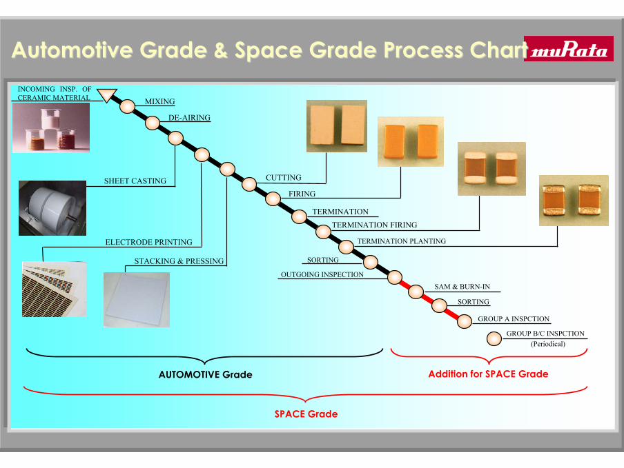
MIXING
DE-AIRING
INCOMING INSP. OFCERAMIC MATERIAL
SHEET CASTING
ELECTRODE PRINTING
STACKING & PRESSING
CUTTING
FIRING
TERMINATION
TERMINATION FIRING
TERMINATION PLANTING
SORTING
GROUP A INSPCTION
OUTGOING INSPECTION
SAM & BURN-IN
SORTING
Addition for SPACE GradeAUTOMOTIVE Grade
GROUP B/C INSPCTION(Periodical)
SPACE Grade
Automotive Grade & Space Grade Process ChartAutomotive Grade & Space Grade Process Chart
15
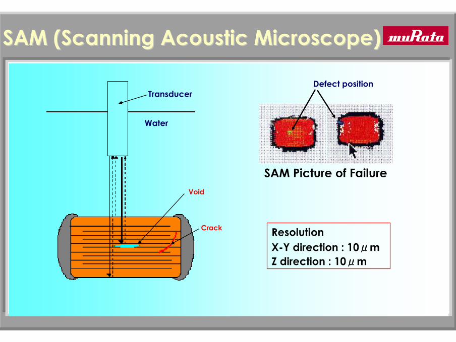
SAM (Scanning Acoustic Microscope)SAM (Scanning Acoustic Microscope)
Water
Transducer
Void
Crack
SAM Picture of Failure
Defect position
ResolutionX-Y direction : 10μmZ direction : 10μm

16
Reliability of Automotive Grade capacitorReliability of Automotive Grade capacitor
FR
=8.3*10-9
=8.3Fit
Failure level Symbol : S (0.001%/1000hrs=10Fit)
Coefficient Number of sampleCoefficient Number of sample
288*3000*AccelerationAcceleration FactorFactor(128*1)
0.917
Voltage Acceleration = (200/50)^3.5 =128
Temperature Acceleration=2^((125-125)/8)=1
Total Number of hours Total Number of hours =
Sample :1206Size X7R 224K 50VDielectric Thickness :16umTest condition :125C-200VNumber of sample units:72pcs-4lots=288Duration :3,000hours
at125C-50V Confidence Level 60%
Acceleration FactorVoltage: 3.5Temperature:8C
=

17
Capacitance Range & Dielectric Thickness Capacitance Range & Dielectric Thickness for Space Grade Capacitorsfor Space Grade Capacitors
TC RATED VOLTAGE(V) CAP.RANGE DIELECTRIC THICKNESS(μm)COG 50 0R5~332 18~137
100 390~182 25~142200 030~391 52~142
X7R 25 221~225 15~4650 221~105 16~66100 102~474 22(SERIES)~130200 152~224 24(SERIES)~28(SERIES)500 102~104 33(SERIES)~37(SERIES)
MIL-PRF-123C MIN DIELECTRIC THICKNESS :0.8mil(20μm) for 50V or 1mil(25.4μm) for ratings above 50V
18
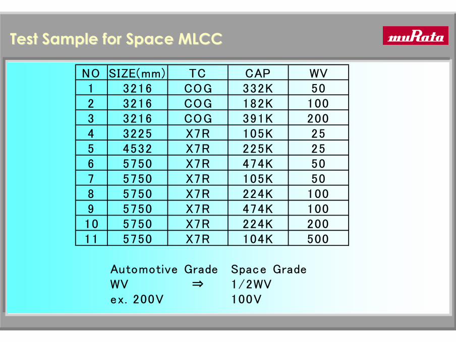
Test Sample for Space MLCCTest Sample for Space MLCC
NO SIZE(mm) TC CAP WV1 3216 COG 332K 502 3216 COG 182K 1003 3216 COG 391K 2004 3225 X7R 105K 255 4532 X7R 225K 256 5750 X7R 474K 507 5750 X7R 105K 508 5750 X7R 224K 1009 5750 X7R 474K 10010 5750 X7R 224K 20011 5750 X7R 104K 500
Automotive Grade Space GradeWV ⇒ 1/2WVex. 200V 100V

19
Qualification Inspection for Space MLCC to JAXAQualification Inspection for Space MLCC to JAXA
Group Item Test Condition ResultⅠ Thermal shock and voltage conditioning -55⇔125℃ 100cycle & 125℃ 2WV 168HR 0/245
Dielectric withstanding voltage 2.5WV 5sec Insulation resistance(25℃/125℃) WV 120secCap,DF COG(1000pFover)&X7R:1kHz1v,COG(1000pFless):1MHz1V
Ⅱ Visual,Dimension Visual inspection,using calipers 0/15Destructive physical analysis Cutting,Grinding
Ⅲ Terminal strength MIL-STD-202 method 211 0/4Solderability of Termination MIL-STD-202 method 208 230℃ 5sec 0/4Resistance to Soldering Heat MIL-STD-202 method 210 260℃ 10sec 0/4
Ⅳ Voltage temperature limits +25/-55/-125℃ WV 0/12Moisture resistance MIL-STD-202 method 106 20cycle 50VorWV
Ⅴ Humidity Steady State Low voltage MIL-STD-202 method 106A 85℃ 85%RH 240HR 1.3V 0/12Vibration MIL-STD-202 method 213/214 0/10Thermal shock MIL-STD-202 method 107 -55⇔125℃ 100cycle 0/18
Ⅵ Life MIL-STD-202 method 108 125℃ 2WV 4000HR 0/123
20
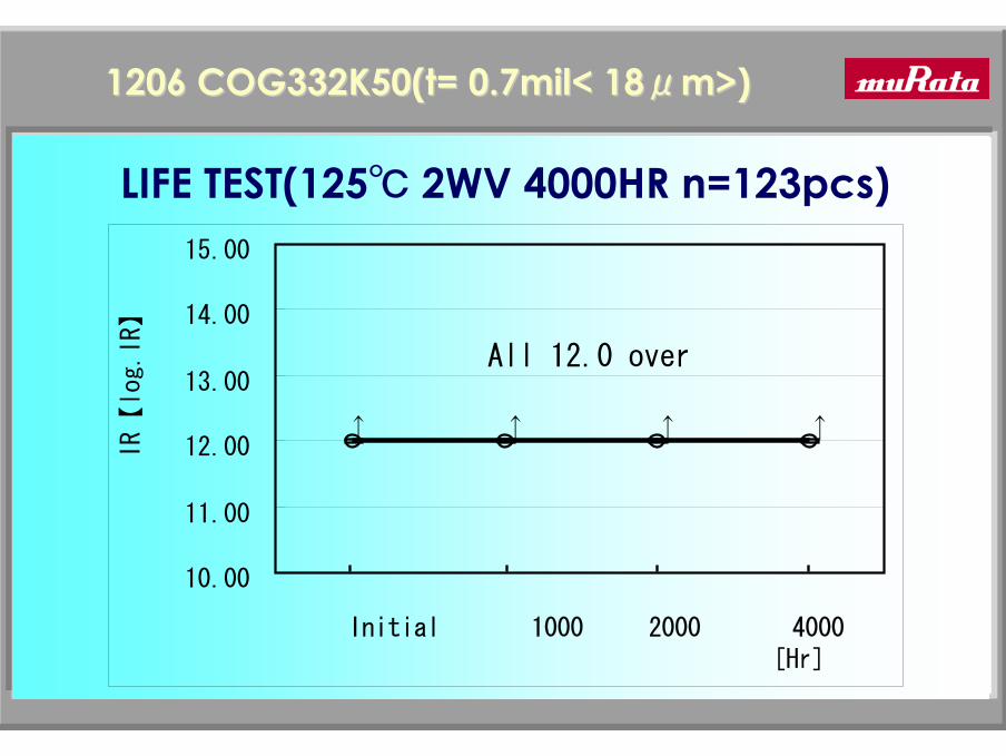
1206 COG332K50(t= 0.7mil< 181206 COG332K50(t= 0.7mil< 18μμm>)m>)
All 12.0 over
10.00
11.00
12.00
13.00
14.00
15.00
Initial 1000 2000 4000[Hr]
IR【
log.IR】
↑ ↑↑ ↑
LIFE TEST(125℃ 2WV 4000HR n=123pcs)

21
1210 X7R105K25(t= 0.6mil< 151210 X7R105K25(t= 0.6mil< 15μμm >)m >)
9.00
9.50
10.00
10.50
11.00
Initial 1000 2000 4000[Hr]
IR【log.IR】
LIFE TEST(125℃ 2WV 4000HR n=123pcs)

22
8.50
9.00
9.50
10.00
10.50
Initial 1000 2000 4000[Hr]
IR【
log.IR】
1812 X7R225K25(t= 0.6mil< 151812 X7R225K25(t= 0.6mil< 15μμm >)m >)
LIFE TEST(125℃ 2WV 4000HR n=123pcs)

23
1812 X7R225K25(t= 0.6mil< 151812 X7R225K25(t= 0.6mil< 15μμm >)m >)
8.50
9.00
9.50
10.00
10.50
50 100 250 500 1000[cycle]
IR【
log.IR】
THERMAL SHOCK(-65℃-+125℃ n=18pcs)
24
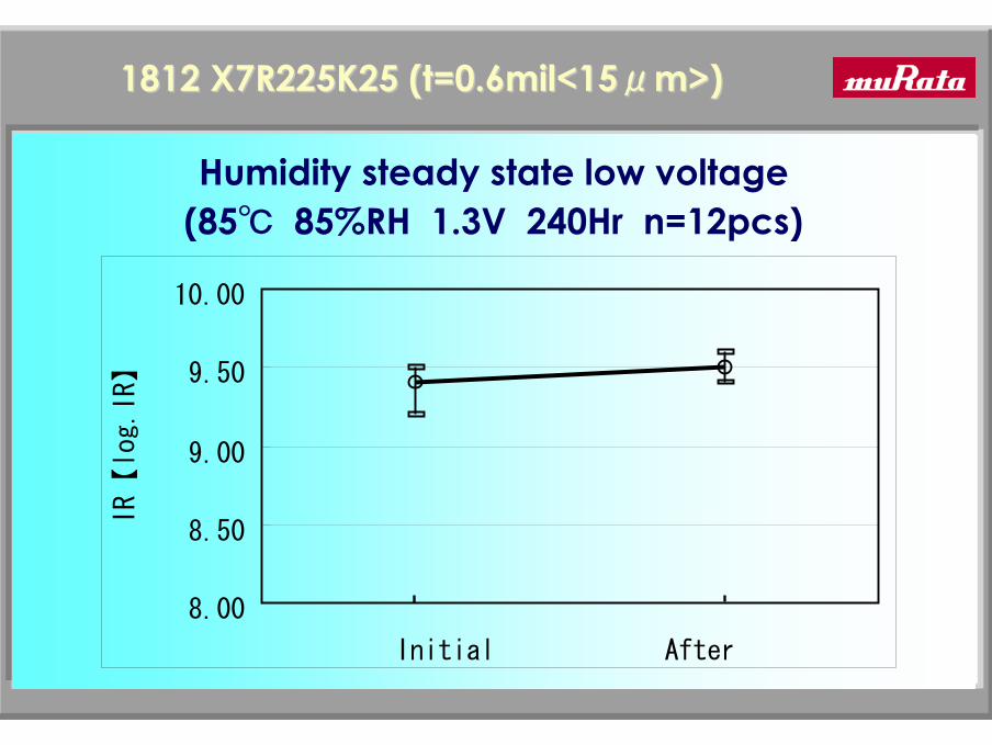
1812 X7R225K25 (t=0.6mil<151812 X7R225K25 (t=0.6mil<15μμm>)m>)
8.00
8.50
9.00
9.50
10.00
Initial After
IR【
log.IR】
Humidity steady state low voltage(85℃ 85%RH 1.3V 240Hr n=12pcs)

25
①GRK-R42-6COG332K50
②GRK-R42-6COG182K100
③GRK-R42-6COG391K200
Tin Whisker(Thermal shock Tin Whisker(Thermal shock --3030⇔⇔100100℃℃1000cycle)1000cycle)

26
ConclusionsConclusions
1. JAXA and MURATA have co-developed MLCC for Space applications derived from existing Automotive grade capacitors (SAM and additional burn in tests).
2. Although, the dielectric thickness of MLCC for Space application is below 0.8mil (MIL-PRF-123C spec.), our tests show the reliability to be high and meeting MIL life test condition(125℃ 2WV 4000HR ).

27
APPENDIX
28
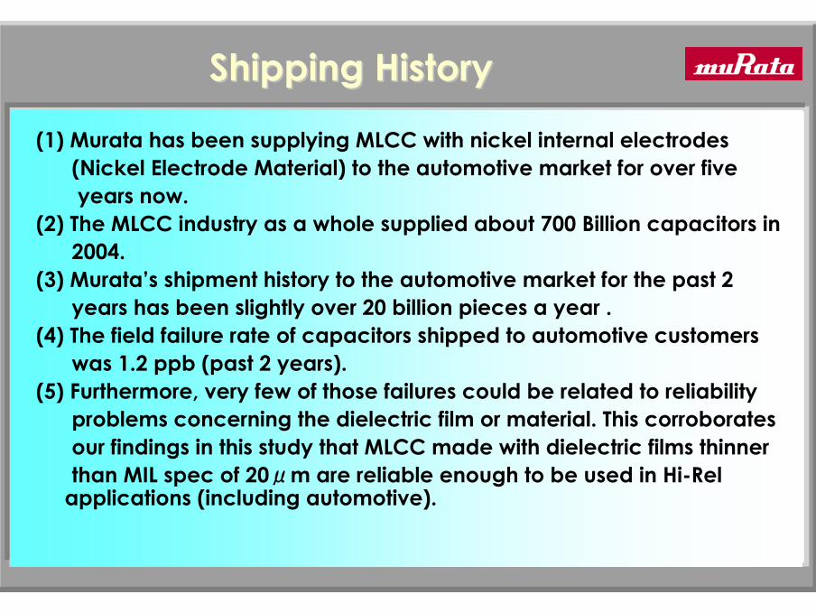
Shipping HistoryShipping History
(1) Murata has been supplying MLCC with nickel internal electrodes (Nickel Electrode Material) to the automotive market for over five years now.
(2) The MLCC industry as a whole supplied about 700 Billion capacitors in 2004.
(3) Murata’s shipment history to the automotive market for the past 2 years has been slightly over 20 billion pieces a year .
(4) The field failure rate of capacitors shipped to automotive customers was 1.2 ppb (past 2 years).
(5) Furthermore, very few of those failures could be related to reliability problems concerning the dielectric film or material. This corroborates our findings in this study that MLCC made with dielectric films thinner than MIL spec of 20μm are reliable enough to be used in Hi-Rel
applications (including automotive).

29
1E+2
1E+3
1E+4
1E+5
1E+6
I.R.
(M o
hm)
INITIAL AFTER TEST
ReliabilityReliability of Ni and Pd electrode MLCCof Ni and Pd electrode MLCC
HIGH TEMPERATURE LOAD HUMIDITY LOAD
TEST CONDITION: TEMPERATURE : 40 +/- 2deg. C
HUMIDITY : 90 ~ 95%RH
VOLTAGE : 25 VDC
DURATION : 500 +/- 12 HOURS
TEST CONDITION: TEMPERATURE : 125 +/- 3deg. C
VOLTAGE : 50 VDC
DURATION : 1000 +/- 12 HOURS
Ni electrodePd electrode0805 Size X7R 100nF 25V
n=18pcs
1E+2
1E+3
1E+4
1E+5
1E+6
I.R.
(M o
hm)
INITIAL AFTER TEST
n=18pcs
30
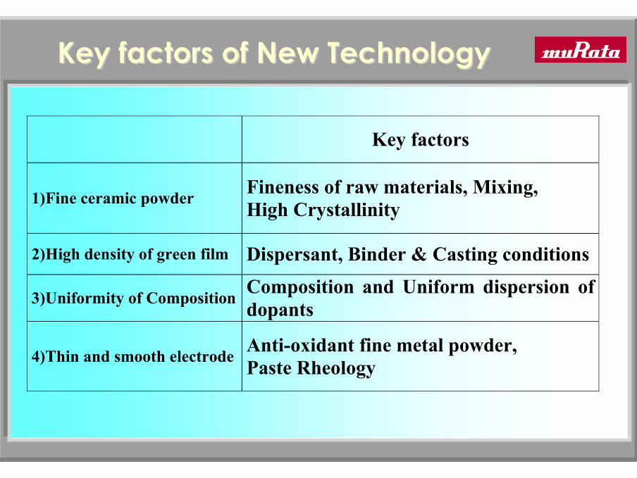
Key factors of New TechnologyKey factors of New Technology
Key factors
1)Fine ceramic powder Fineness of raw materials, Mixing, High Crystallinity
2)High density of green film Dispersant, Binder & Casting conditions
3)Uniformity of Composition Composition and Uniform dispersion of dopants
4)Thin and smooth electrode Anti-oxidant fine metal powder, Paste Rheology
31
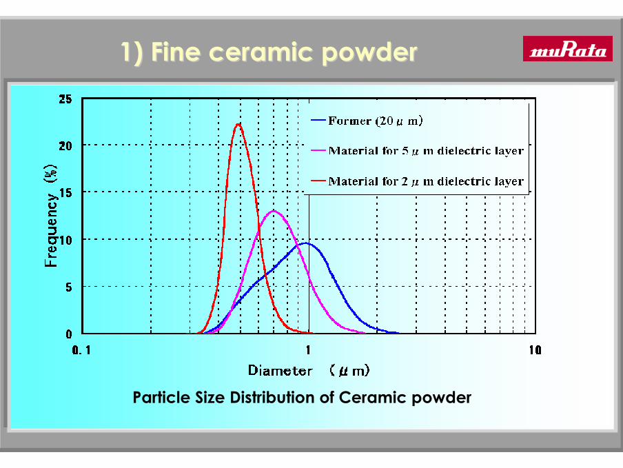
1) Fine ceramic powder1) Fine ceramic powder
Particle Size Distribution of Ceramic powder

32
FE-SEM: Surface of green film
2) High density of green film 2) High density of green film
Former Current
Pore2umHigh density
Fine ceramic powder

33
2um
FIB-SIM: Cross section of green film
Pore
High density of green Sheet High density of green Sheet
Former Current

34
FIBFIB--SIMSIM
Angle of incidence : 5deg.Angle of incidence : 5deg.
FIB:Focused Ion BeamSIM:Scanning Ion Microscope Ga Ion Beam
Detector
Angle of observation picture : 45deg.Angle of observation picture : 45deg.
SIMSIM--PicturePicture
Green SheetGreen Sheet

35
Uniformity of green filmWDX Mapping of Mn (dopant material)
3) Uniformity of Composition3) Uniformity of Composition
agglomerationFormer Current

36
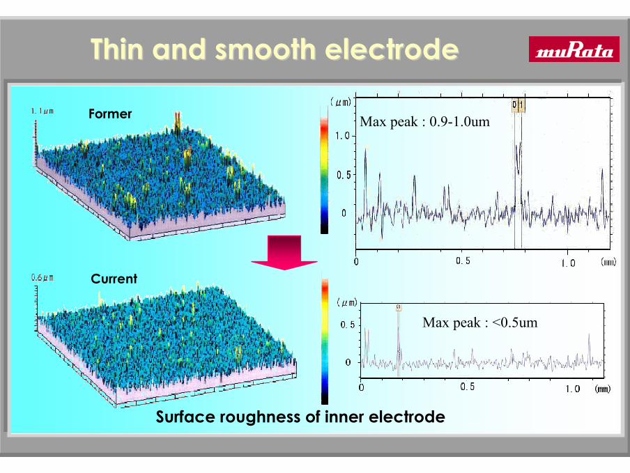
4) 4) Thin and smooth electrodeThin and smooth electrode
2um
FIB-SIM: Cross section of green chip
Former Current
37
Thin and smooth electrodeThin and smooth electrode
Surface roughness of inner electrode
Max peak : 0.9-1.0um
Max peak : <0.5um
Former
Current
38
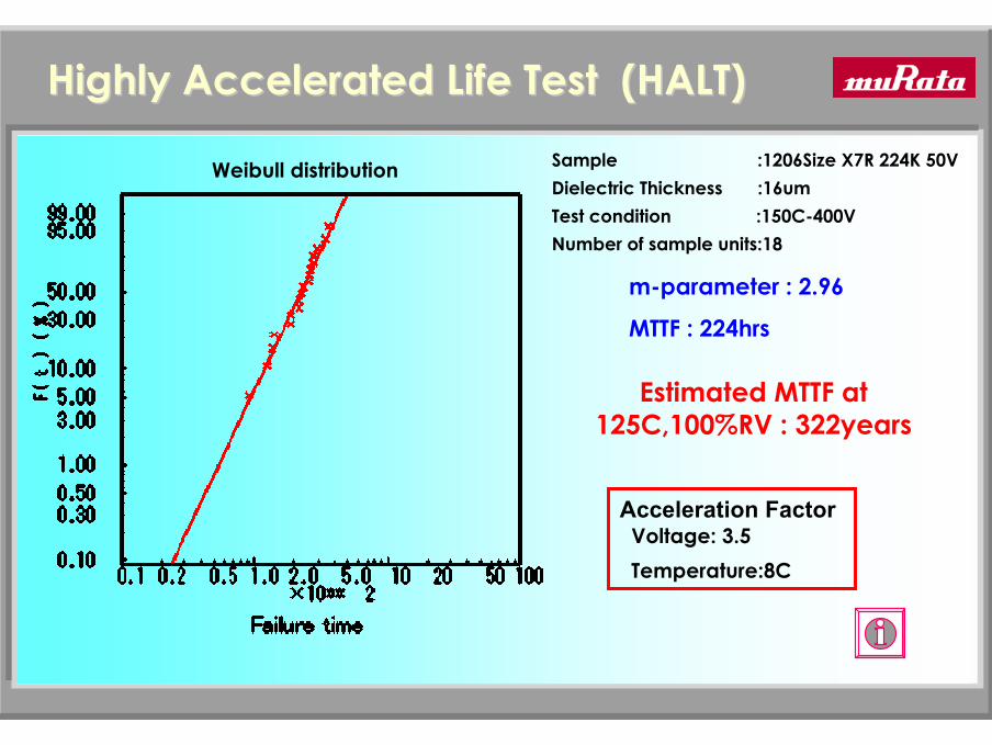
Highly Accelerated Life Test (HALT)Highly Accelerated Life Test (HALT)Sample :1206Size X7R 224K 50VDielectric Thickness :16umTest condition :150C-400VNumber of sample units:18
m-parameter : 2.96
MTTF : 224hrs
Acceleration FactorVoltage: 3.5Temperature:8C
Estimated MTTF at 125C,100%RV : 322years
Weibull distribution

39
Voltage Acceleration : Eyring Model
L = C’ x V- a
Hereby is L : Lifetime C’ : ConstantV : Test Voltage a : Acceleration Factor
MLCC Reliability Design (1)MLCC Reliability Design (1)
AL = LN /LA = (VA /VN)n
Hereby is AL : Acceleration FactorLN : Lifetime under Standard ConditionLA : Lifetime under Accelerated ConditionVN: Temperature Standard ConditionVA: Temperature Accelerated Condition n : Voltage Acceleration Factor

40
MLCC Reliability Design (2)MLCC Reliability Design (2)
Temperature Acceleration: Ahrenius model
L = C X exp { -Ea/(k XT) }Hereby is L : Lifetime C : Constant
Ea : Activated Energy k : Boltzmann FactorT : Absolute Temperature
AL = LN /LA = 2( t/b )
Hereby is AL : Acceleration FactorLN : Lifetime under Standard ConditionLA : Lifetime under Accelerated Conditiont : Temperature Difference between
Standard & Accelerated Conditionb : Temperature Acceleration Factor
41
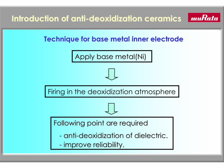
Introduction of antiIntroduction of anti--deoxidization ceramicsdeoxidization ceramics
Technique for base metal inner electrodeTechnique for base metal inner electrode
Apply base Apply base metal(Nimetal(Ni))
Firing in the deoxidization atmosphere
Following point are requiredFollowing point are required
-- antianti--deoxidization of dielectric.deoxidization of dielectric.-- improve reliability.improve reliability.