Embed Size (px)
Citation preview

AbstractThe proposed paper deals with the development process and initial measurement results of an opposed-piston combustion engine for application in a Free-Piston Linear Generator (FPLG). The FPLG, which is being developed at the German Aerospace Center (DLR), is an innovative internal combustion engine for a fuel based electrical power supply. With its arrangement, the pistons freely oscillate between the compression chamber of the combustion unit and a gas spring with no mechanical coupling like a crank shaft. Linear alternators convert the kinetic energy of the moving pistons into electric energy. The virtual development of the novel combustion system is divided into two stages: On the one hand, the combustion system including e.g. a cylinder liner, pistons, cooling and lubrication concepts has to be developed. On the other hand, 3D-CFD-simulations are used in the early stage within the virtual development process toward the optimization of the geometry of the scavenging ports and ducts, the gas exchange, injection and ignition. With the high variability of the free piston concept, a strategy for a dual combustion mode operation with spark ignition and homogeneous charge compression ignition (HCCI) is developed. The new engine is constructed on and implemented at a hydraulic free-piston test bench at DLR which controls the piston movements by two hydraulic actuators. In this stage, the power is not converted by linear generators yet. First measurement results show the engine behavior with dual spark ignition and two opposed injectors.
IntroductionDue to stricter fuel consumption and CO2 emission standards the opposed-piston engine has attracted the interest of the automotive industry recently. In the 1930s the historical Junkers Jumo opposed-piston engines already reached specific fuel consumptions of 231 g/kWh and less [1]. Nowadays several companies like Achates Power or Ecomotors are working on this engine concept regarding emissions and fuel economy for road vehicles [3, 8, 14, 15, 7, and 2]. Based on the simple design of the engine with no cylinder head, complex valve train or camshaft it has also the potential for a higher power density and a reduction of production costs [17]. In other research groups, the approach of the opposed-piston engine is used for the combustion chamber in a free-piston engine [22, 5, 12, and 6]. However, published measurement results are limited due to the high complexity of controlling the two opposed free-piston movements. To overcome these problems the present paper deals with the first step in a systematical development approach for an opposed-piston combustion chamber in a Free-Piston Linear Generator (FPLG).
Function Principle of the Free-Piston Linear Generator in Opposed-Piston DesignThe FPLG as implemented by DLR is a free-piston engine for the conversion of chemically stored energy in fuels to electric energy. The structure of the FPLG consists of three different subsystems: combustion unit, linear generator and gas spring. The opposed-piston design as illustrated in Figure 1 consists of one opposed-piston combustion unit (CB) with one linear generator (LG) and gas spring (GS) on each side.
Development and Experimental Investigation of a Two-Stroke Opposed-Piston Free-Piston Engine
2016-32-0046
20168046
Published 11/08/2016
Stephan SchneiderGerman Aerospace Center (DLR)
Marco ChiodiFKFS
Horst FriedrichGerman Aerospace Center (DLR)
Michael BargendeFKFS
CITATION: Schneider, S., Chiodi, M., Friedrich, H., and Bargende, M., "Development and Experimental Investigation of a Two-Stroke Opposed-Piston Free-Piston Engine," SAE Technical Paper 2016-32-0046, 2016, doi:10.4271/2016-32-0046.
Copyright © 2016 SAE International
Downloaded from SAE International by Stephan Schneider, Monday, October 24, 2016
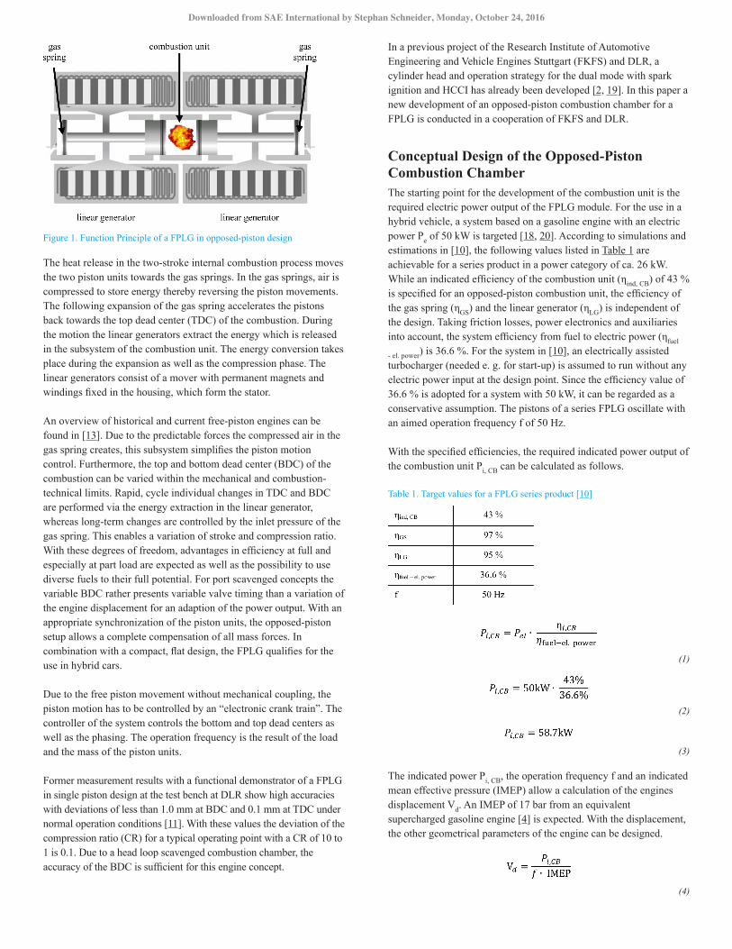
Figure 1. Function Principle of a FPLG in opposed-piston design
The heat release in the two-stroke internal combustion process moves the two piston units towards the gas springs. In the gas springs, air is compressed to store energy thereby reversing the piston movements. The following expansion of the gas spring accelerates the pistons back towards the top dead center (TDC) of the combustion. During the motion the linear generators extract the energy which is released in the subsystem of the combustion unit. The energy conversion takes place during the expansion as well as the compression phase. The linear generators consist of a mover with permanent magnets and windings fixed in the housing, which form the stator.
An overview of historical and current free-piston engines can be found in [13]. Due to the predictable forces the compressed air in the gas spring creates, this subsystem simplifies the piston motion control. Furthermore, the top and bottom dead center (BDC) of the combustion can be varied within the mechanical and combustion-technical limits. Rapid, cycle individual changes in TDC and BDC are performed via the energy extraction in the linear generator, whereas long-term changes are controlled by the inlet pressure of the gas spring. This enables a variation of stroke and compression ratio. With these degrees of freedom, advantages in efficiency at full and especially at part load are expected as well as the possibility to use diverse fuels to their full potential. For port scavenged concepts the variable BDC rather presents variable valve timing than a variation of the engine displacement for an adaption of the power output. With an appropriate synchronization of the piston units, the opposed-piston setup allows a complete compensation of all mass forces. In combination with a compact, flat design, the FPLG qualifies for the use in hybrid cars.
Due to the free piston movement without mechanical coupling, the piston motion has to be controlled by an “electronic crank train”. The controller of the system controls the bottom and top dead centers as well as the phasing. The operation frequency is the result of the load and the mass of the piston units.
Former measurement results with a functional demonstrator of a FPLG in single piston design at the test bench at DLR show high accuracies with deviations of less than 1.0 mm at BDC and 0.1 mm at TDC under normal operation conditions [11]. With these values the deviation of the compression ratio (CR) for a typical operating point with a CR of 10 to 1 is 0.1. Due to a head loop scavenged combustion chamber, the accuracy of the BDC is sufficient for this engine concept.
In a previous project of the Research Institute of Automotive Engineering and Vehicle Engines Stuttgart (FKFS) and DLR, a cylinder head and operation strategy for the dual mode with spark ignition and HCCI has already been developed [2, 19]. In this paper a new development of an opposed-piston combustion chamber for a FPLG is conducted in a cooperation of FKFS and DLR.
Conceptual Design of the Opposed-Piston Combustion ChamberThe starting point for the development of the combustion unit is the required electric power output of the FPLG module. For the use in a hybrid vehicle, a system based on a gasoline engine with an electric power Pe of 50 kW is targeted [18, 20]. According to simulations and estimations in [10], the following values listed in Table 1 are achievable for a series product in a power category of ca. 26 kW. While an indicated efficiency of the combustion unit (ηind, CB) of 43 % is specified for an opposed-piston combustion unit, the efficiency of the gas spring (ηGS) and the linear generator (ηLG) is independent of the design. Taking friction losses, power electronics and auxiliaries into account, the system efficiency from fuel to electric power (ηfuel
- el. power) is 36.6 %. For the system in [10], an electrically assisted turbocharger (needed e. g. for start-up) is assumed to run without any electric power input at the design point. Since the efficiency value of 36.6 % is adopted for a system with 50 kW, it can be regarded as a conservative assumption. The pistons of a series FPLG oscillate with an aimed operation frequency f of 50 Hz.
With the specified efficiencies, the required indicated power output of the combustion unit Pi, CB can be calculated as follows.
Table 1. Target values for a FPLG series product [10]
(1)
(2)
(3)
The indicated power Pi, CB, the operation frequency f and an indicated mean effective pressure (IMEP) allow a calculation of the engines displacement Vd. An IMEP of 17 bar from an equivalent supercharged gasoline engine [4] is expected. With the displacement, the other geometrical parameters of the engine can be designed.
(4)
Downloaded from SAE International by Stephan Schneider, Monday, October 24, 2016

(5)
(6)
The dimensioning of cylinder bore and piston stroke is based on an extensive investigation in [16]. Regarding an area-to volume analysis, the scavenging efficiency and engine friction, a stroke-to-bore ratio of 2.0 or higher is advantageous for high efficiencies. Although the friction loss increases with a stroke-to-bore ratio exceeding a value of 2.3, the other effects have a stronger influence on the efficiency. Additionally, free-piston engines are characterized by the linear movement without lateral forces, whereby the effect of friction is reduced. With a stroke per piston of 87 mm and a cylinder bore of 71 mm, the stroke-to-bore ratio of the designed opposed-piston combustion unit is 2.5.
The layout of the engine is presented in Figure 2. A supercharger with an intercooler is used to accomplish the pressure difference for the scavenging of the combustion chamber. The port timing of the intake and exhaust ports is defined by the piston trajectories. Since the piston movement is not fixed by the crank train, the timing of intake / exhaust open and close can be varied during operation within the mechanical limits. Hence, these fundamental parameters do not have to be defined as set parameters during the virtual development of the combustion chamber. Due to these inherent degrees of freedom, the option to insert complex design features like e.g. flaps in the intake or exhaust is discarded for this design.
Figure 2. Schematic of the opposed-piston engine
To avoid unburned hydrocarbon (UHC) emissions due to fresh charge leaking out through the exhaust ports, a direct injection takes place after the ports are closed. The fuel injection is positioned in the cylinder liner between the two pistons’ TDC. A spark plug, also mounted radially in the center of the cylinder liner, accomplishes the starting of the engine and is used for the combustion process at high loads. For part load operation points a homogeneous charge compression ignition is to be used for high efficiencies and low raw emissions [25].
In this early stage of development, the pistons of the combustion unit are not coupled to linear generators and gas springs. The movement of the two pistons is defined by an opposed-piston free-piston test bench, which will be described in the next section.
Test BenchInstead of a freely oscillating FPLG system with a high complexity of e.g. the new control algorithm, an opposed piston free-piston test bench is developed for the first experimental investigations of the combustion unit. The main aim of this testing system is to provide a safe piston movement according to the adjusted trajectory even in cases of stochastic cycle variations or misfiring events. This requirement can be compared to a conventional crank train with the inertia of the flywheel. However, variations of stroke or compression ratio during operation cannot be achieved by this approach with acceptable effort.
The combination of a safe operation with variable trajectories is met by the use of hydraulic working pistons. Therefore, two oppositely arranged double-action cylinders by Hänchen are customized with aluminum plungers. The oil flow is controlled by a three stage proportional Moog servo valve. For the position control, a high precision incremental displacement measurement system by Balluff detects the plunger and consequently the piston position. The test bench setup with the opposed hydraulic cylinders is shown in Figure 3.
The hydraulic pressure of 300 bar allows plunger forces of up to 56 kN. The maximum hydraulic oil flow rate for the supply of the two cylinders is defined by the hydraulic pumps with 1,000 l/min. With that, the operation frequency of the system is limited at approximately 15 Hz. Although operation frequencies of 25-30 Hz are aimed for a functional demonstrator respectively 50 Hz for a series product, 15 Hz is sufficient for an initial investigation of the engine behavior.
Figure 3. Hydraulic opposed-piston test bench
Downloaded from SAE International by Stephan Schneider, Monday, October 24, 2016

Virtual Engine DevelopmentThe target of a full virtual engine development is an ambitious task that, if successful, allows shortening the development time and remarkably reducing the related costs. For this task the 3D-CFD simulation is a very powerful tool if it is able to match the given development time by investigating a sufficient number of promising variants with reliable results. In particular, 3D-CFD simulations are able to provide a deep insight into the occurring thermodynamic processes; as like a virtual eye even in the most remote parts of the engine. In many cases, these simulations can be de facto implemented as a more versatile device than experimental measurements which are not able e.g. to capture important fluid dynamical details like local temperature, residual gas concentration, turbulence, etc. Based on the deep understanding of the occurring phenomena, it is possible to elaborate new operating strategies or engine designs. Therefore, long before the realization of the first real prototype, it is possible to have already performed many virtual development loops with effective engine performance increasing. As soon as the first prototype is on the test bench, intensive experimental investigations are mandatory, among other things, in order to verify the results and validate the virtual development process.
QuickSimFor the numerical analysis, the 3D-CFD tool QuickSim is employed. This tool was developed and constantly enhanced over the past years, in order to allow comprehensive studies and virtual development of internal combustion engines (ICE). Hereby, no restrictions of the engine layout, geometries, valve timings, injection strategies or fuel types are given and the full flexibility of the free-piston engine can be regarded. Using computational models, specifically adapted to the application in ICE (e. g. for the wall heat transfer), QuickSim allows the use of relatively coarse meshes compared to traditional approaches without a loss of accuracy but highly reducing the computational time (up to factor 100). For this reason, the simulation domain can be extended to the full engine and several consecutive operating cycles can be simulated, minimizing the influence of boundary and initial conditions. Some information on the simulation setup for the presented analysis is listed in Table 2. For more details, especially on implemented models, the reader may refer to [1, 24, 9, 21 and 23].
In this particular development of an opposed-piston engine it is mandatory to ensure a reliable 3D-CFD simulation already at a stage at which calibration data or even reference data are not available. Since boundary conditions in the intake and exhaust manifold cannot be reliably provided (only an uncalibrated 1D-CFD model would be available) the simulated domain is extended to the whole test bench, i.e. including the complete intake and exhaust system (Figure 4). Thus the influences of the boundary and initial conditions are reduced. Based on this approach the boundary conditions are simply described by the environmental conditions and they do not change by testing different engine geometries (high predictability of the results). Due to the extension of the fluid domain, many operating cycles are required in order to achieve convergence of the results. Depending on the engine operating point, the convergence can be reached after approx. 5-8 cycles.
Table 2. General simulation models and parameters
Figure 4. 3D-CFD mesh of the test bench
After having reached the convergence in any case engine performance data (filling, EGR, combustion duration etc.) continue varying around an average value due to cyclic variations within the exchange and high-pressure period, which may be linked to the real engine cycle-to-cycle variations. Thanks to the reduced computation time of each operating cycle (for this engine about 4 hours with one single CPU dedicated to the simulation) it is possible to simulate also small transients (up to ca. 80 cycles) within an acceptable overall time frame. For this engine, small transient 3D-CFD simulations are mainly performed in order to investigate the switch mechanism between spark ignition (SI) and HCCI operation.
Development ProcessThe virtual engine development described in this section is divided into the thermodynamic simulation of the scavenging and combustion with 3D-CFD tools and the design of e.g. the cylinder, ports, pistons, cooling and lubrication. Both stages are performed in an iterative process, which is illustrated in Figure 5. After virtually testing different scavenging concepts for the dual operation of SI and HCCI, the operation and basic geometry is defined with the concept freeze. After further development, the design freeze takes place and fundamental engine components such as the cylinder liner and the engine block are ready for the prototype manufacturing. However, minor changes e.g. the fuel injection, ignition or the port timing can still be fine-tuned with further simulations.
Downloaded from SAE International by Stephan Schneider, Monday, October 24, 2016

Figure 5. Development methodology
Focusing now on the virtual engine development based on 3D-CFD simulations, especially in such a complex engine concept without references, it is very important to implement an efficient trial-anderrors approach with the aim to lead to a successful learning process through all the development loops. Based on simulation results and engine performance expectations, new engine designs (geometries of the intake and exhaust ports, piston shape, injector type and location, spark plug type and location, etc.) and operational strategies (e.g. piston trajectories, injection and timings) can be elaborated and tested. In the decision process, among promising variants, simple and operationally stable ones should be always prioritized. The target of the engine development was to avoid implementing additional valves or throttle devices in the intake or exhaust system for the regulation of the scavenging process. This target during the project has been achieved: i.e. only the piston trajectories that directly influence the port openings are responsible for this process.
Engine Simulation ResultsThe results shown in this section are just a short selection of more than 100 engine variants investigated since the aim of this paper is to describe the road map towards the virtual engine development of this particular engine. Future publications will present more detailed descriptions of the thermodynamic phenomena and engine operation peculiarities.
Development Stage 0The first engine design (DEV_STAGE_0) investigated by means of 3D-CFD simulations is realized in a CAD model based only on general considerations and ideas about the operation of this unusual engine concept. Dimensions and positions of the intake and exhaust ports have been also estimated (see Table 3). Therefore, at this stage, 3D-CFD simulations mainly help to understand how the scavenging process works (beginning of the learning process).
Table 3. Engine Data of DEV_STAGE_0
As shown in Figure 6, the first engine variant has one ring of intake ports with charge supply from a two manifolds design in order to generate a swirl in the combustion chamber for a better mixture formation. The same concept is used also for the exhaust system. The chosen trajectories of both pistons are absolutely symmetric to the intake and exhaust ports, i.e. the engine has the same intake and exhaust timings for the scavenging process. As described in the second section, symmetric piston trajectories are aimed in order to achieve a completely mass balanced system.
Figure 6. First engine design scheme (DEV_STAGE_0)
The operating condition in the 3D-CFD simulation is set at 20 Hz (1200 rpm) with a boost pressure of 2 bar (absolute). The BDCs are fixed at a distance X_BDC of 2 mm beyond the ports (see Figure 7, where X_BDC=0 means BDC of the piston at the widest point of the port), which determines an opening duration of 122° CA assuming a piston motion with an equivalent crankshaft with a r/l ratio of 0.36 (BDC=180 °CA). The higher X_BDC the longer is the duration of port opening. The first results showed a very poor performance of the engine. The charge overflow from intake to exhaust is excessive, which leads to a very low trapping efficiency (ratio between trapped cylinder air mass and aspirated air through the port). In addition, the design of the intake and exhaust rings definitely generates a too high swirl with negative effects to the combustion process and engine stability (see Figure 8 and Figure 9).
As described below, the trapping efficiency can be influenced by using different piston trajectories (reducing the opening durations of the ports) but towards a reduction of the swirl ratio, a new engine design is necessary.
Figure 7. Uniflow scavenging scheme
The peculiarity of the free piston concept is the high kinetic variability that allows influencing both the scavenging process (opening duration of the ports) and the compression ratio. This is possible although the concept based on intake and exhaust ports is geometrically more rigid
Downloaded from SAE International by Stephan Schneider, Monday, October 24, 2016

compared to a valve train concept, where the exchange process in not directly linked to piston motion. In particular, for a given geometry of the combustion chamber liner (relevant is the distance between the intake and exhaust ports), the X_BDC position influences the scavenging process. The higher X_BDC, the longer the port remains open. If required it is also possible to use different positions X_BDC for piston 1 and 2 allowing different durations of the intake and exhaust opening phase. The choice of the TDC, on the other side, mainly regulates the compression ratio. According to this approach, during the regular operation (either SI or HCCI operation) it is convenient to set the BDC constant and to vary, if necessary (e.g. during the HCCI operation) the TDC. During the switch from SI to HCCI operation, as it will be explained later, an additional variation of BDC is mandatory.
Figure 8. Swirl of the charge in the combustion chamber for DEV_STAGE_0 at 20 Hz
Due to the very fast scavenging process and low trapping efficiency (ca. 40 %), it is needful to inject the fuel only after the closure of the exhaust port. Otherwise, part of the injected fuel would directly flow into the exhaust system causing very high emissions and fuel consumption.
Figure 9. Analysis of the scavenging process (mass flows through the ports and cylinder filling) for DEV_STAGE_0 at 20 Hz
Development Stage 1Based on the first virtual results, a new engine design is realized. At this stage, the dimensions of the ports are kept constant to the DEV_STAGE_0 but the connection points between manifolds and the port rings are now symmetric. In that way the swirl motions within the port rings are not generated anymore (see Figure 10). In this case, the
flow motion within the combustion chamber is more regular with less distortion of the flame during propagation, which leads to a faster and more efficient fuel heat release.
Figure 10. Engine design scheme (DEV_STAGE_1)
As shown in the Figure 11, Figure 12 and Figure 13, the scavenging process of the engine can be varied by modifying the X_BDC or the boost pressure. Moreover at this development stage it is important to start analyzing residual gas concentration and how this can be influenced by different exchange process strategies. For SI operating conditions, residual gas concentration should be kept as low as possible while for HCCI operations higher residual gas mass fractions (ca. 40 %) are necessary at these engine speeds in order to limit pressure gradients within reasonable ranges. The implementation of external residual gas recirculation would not be a solution both due to engine efficiency decrease because of additional work required by the charger and due to a lower response in comparison to internal residual gas regulation. Especially during the transition from SI to HCCI operation it is mandatory to switch residual gas concentration between two subsequent cycles.
Figure 11. Analysis of the scavenging process (mass flows through the ports and cylinder filling) for DEV_STAGE_1 at 20 Hz with charger pressure at 2.0 bar
Scavenging process analyses show that by varying the BDCs of the piston, the mass flows through the ports do not change remarkably. Here the results are reported for the cases X_BDC=0 mm with BDC at the bottom of the ports and X_BDC=-2 mm which means the ports will not be completely opened, i.e. a reduction of the effective area of the ports. These BDC variations show fewer differences than expected. At the beginning of the scavenging phase, the pressure in
Downloaded from SAE International by Stephan Schneider, Monday, October 24, 2016

the cylinder is higher than in both manifolds, therefore the exhaust gas flows into both ports. As soon as the pressure in the cylinder decreases to the level of the boost pressure, the relevant scavenging process starts. Due to the very high pressure difference between intake and exhaust manifold, the fresh charge rapidly moves through the combustion chamber to the exhaust port, leading to an excessive scavenging (significant reduction of trapping efficiency). As shown in the scavenging analyses for boost pressure = 2.0 bar, the maximal cylinder filling is reached long before port closing. The trapping efficiency in both cases is still < 50 %. This trapping efficiency is neither convenient for the energy consumed by the compressor nor for the catalyst required temperature.
Figure 12. Analysis of the scavenging process (mass flows through the ports and cylinder filling) for DEV_STAGE_1 at 20 Hz with charger pressure at 1.5 bar
By varying the boost pressure (see Figure 13 for pboost= 1.5 bar), the scavenging process changes remarkably and as expected the cylinder filling decreases (trapping efficiency up to 60%). However, also in this case the influence by the variation of X_BDC still remains moderate. Additional reductions of the boost pressure are not recommended because the engine behavior becomes unstable and the specific power remarkably drops (min pboost = ca. 1.3 bar and up to X_BDC=-5 mm which allows a trapping efficiency up to 75 %).
Figure 13. Analysis of the residual gas mass concentration for DEV_STAGE_1 at 20 Hz
The performed virtual investigations show that it is possible to influence the residual gas concentrations (see Figure 13), but, even with very low X_BDC values, not in a range that allows stable operating conditions with the required residual gas concentration for HCCI operation. This engine variant has a too effective scavenging from the intake to the exhaust port supported by a high boost pressure, which is necessary for a good combustion chamber filling towards a stable operating condition. During the “uniflow scavenging”, the fresh charge moves like an air piston from the intake to the exhaust port. In order to a have a high concentration of residual gas, the exhaust port must be closed long before the fresh charge front reaches the center of the combustion chamber. Since the density of the residual gas (higher temperature), is much lower than the fresh charge one, 40 % of residual gas mass fraction is approximately 70 % of the combustion chamber volume. In case of HCCI operation, in order to reduce the scavenging efficiency a reliable port opening strategy must be identified accurately (e.g. very short intake opening duration, very short exhaust opening duration, or a combination of both). As already mentioned, for this engine design it was not possible to find a stable operating condition for HCCI operation even applying asymmetric port opening strategies.
Development Stage N (Bilateral Scavenging)Among many variants tested, also a special design capable of HCCI operation is virtually tested. As shown in Figure 14 and Figure 15 this design has a bilateral scavenging on both BDC positions of the pistons (“cross scavenging”). Therefore, the scavenging process is less effective in the middle of the combustion chamber allowing a higher residual gas concentration. In case of SI operation, the basic idea is to use an additional throttle to close at least one intake port ring (unilateral air flow to the combustion chamber) in order to establish a combination of longitudinal and highly effective cross scavenging. An additional throttle in the exhaust manifold, in order to close also one exhaust port, has been simulated in some cases but is definitively not recommended due to mechanical stress (high temperature of the exhaust gas).
Figure 14. Engine design scheme with bilateral scavenging concept (DEV_STAGE_N)
Scavenging process analyses show that using very low X_BDC values (up to X_BDC=-6 mm. i.e., the ports are opened as few as 70 % of their areas) it is possible to reach residual gas concentrations required by HCCI operations. As reported in the scavenging process analyses, the maximal cylinder air mass trapped is much lower under this operation condition, which as expected causes a remarkable reduction of the specific engine power.
Downloaded from SAE International by Stephan Schneider, Monday, October 24, 2016

Figure 15. Bilateral scavenging scheme
The cylinder filling can be mainly and efficiently varied with the boost pressure. In particular, the lower the boost pressure the longer the ports can remain open with advantages for the global engine efficiency (less work required by the external compressor). However, the scavenging duration is ca. 50 % shorter than for a stable operation of the DEV_STAGE_1 variant, otherwise due to the vicinity of the intake and exhaust ports the trapping efficiency would be unacceptably reduced (maximal trapping efficiency reached is ca. 75 % with 40 % residual gas mass fraction). Interesting engine behavior results are achieved with a boost pressure of 1.5 bar (best compromise between engine specific power and efficiency). With lower boost pressures the engine becomes unstable.
Figure 16. Analysis of the scavenging process with all ports open (mass flows through the ports and cylinder filling) for DEV_STAGE_N at 20 Hz and different charger pressures
The developed variant with bilateral scavenging is an interesting concept for an HCCI operation since it allows operating with higher residual gas concentrations under stable conditions. The engine power is adequate for this target (ca. 4 kW at 20 Hz) but the relatively low trapping efficiency (no more than 75 %) still remains an issue. In addition, in case of SI operation, the scavenging process is less effective, as long as complex and expensive strategies for the activation of a cross scavenging are not implemented. In summary, this variant is still not a valuable variant for the prototype realization.
Figure 17. Analysis of the residual gas mass concentration with all ports open for DEV_STAGE_N at 20 Hz and different charger pressures
Development Stage for the first released PrototypeAfter several virtual developments loops, a final geometry for the first prototype release is designed. As shown in Figure 18 in comparison to the DEV_STAGE_1, this configuration uses one optimized port ring for the intake and exhaust system, respectively. The area of the ports is reduced remarkably in comparison to the previous variants (height of the ports remains constant with 20 mm). Each port ring is then connected only to one manifold. The flow within the ring is also optimized in order to increase the general discharge efficiency by eliminating any flow separation or undesired vortex generation. This variant allows an effective regulation of the residual gas concentration within a single operating cycle so that the switch from SI to HCCI operation and vice versa can be performed successfully. In the center of the liner, 6 radial equidistant holes are placed, which can be used for sensors, spark plugs and fuel injectors. Good performance results and low cycle-to-cycle variations are obtained using 2 spark plugs and 2 fuel injectors (configuration: sp - x - sp - inj - x - inj).
Figure 18. Engine design of the released prototype (DEV_STAGE_Prototype) in comparison to DEV_STAGE_1
Figure 19 and Table 4 show some details regarding the engine operation for SI and HCCI processes. The SI operation (at 20 Hz and pboost=2 bar) has been performed setting a symmetric X_BDC of -6
Downloaded from SAE International by Stephan Schneider, Monday, October 24, 2016
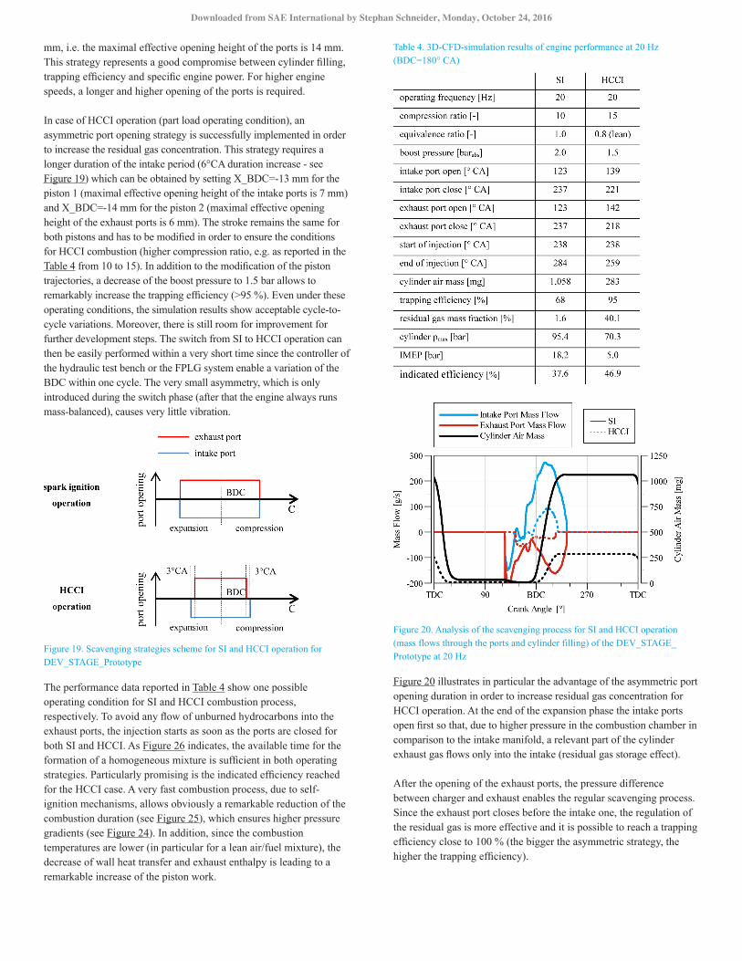
mm, i.e. the maximal effective opening height of the ports is 14 mm. This strategy represents a good compromise between cylinder filling, trapping efficiency and specific engine power. For higher engine speeds, a longer and higher opening of the ports is required.
In case of HCCI operation (part load operating condition), an asymmetric port opening strategy is successfully implemented in order to increase the residual gas concentration. This strategy requires a longer duration of the intake period (6°CA duration increase - see Figure 19) which can be obtained by setting X_BDC=-13 mm for the piston 1 (maximal effective opening height of the intake ports is 7 mm) and X_BDC=-14 mm for the piston 2 (maximal effective opening height of the exhaust ports is 6 mm). The stroke remains the same for both pistons and has to be modified in order to ensure the conditions for HCCI combustion (higher compression ratio, e.g. as reported in the Table 4 from 10 to 15). In addition to the modification of the piston trajectories, a decrease of the boost pressure to 1.5 bar allows to remarkably increase the trapping efficiency (>95 %). Even under these operating conditions, the simulation results show acceptable cycle-to-cycle variations. Moreover, there is still room for improvement for further development steps. The switch from SI to HCCI operation can then be easily performed within a very short time since the controller of the hydraulic test bench or the FPLG system enable a variation of the BDC within one cycle. The very small asymmetry, which is only introduced during the switch phase (after that the engine always runs mass-balanced), causes very little vibration.
Figure 19. Scavenging strategies scheme for SI and HCCI operation for DEV_STAGE_Prototype
The performance data reported in Table 4 show one possible operating condition for SI and HCCI combustion process, respectively. To avoid any flow of unburned hydrocarbons into the exhaust ports, the injection starts as soon as the ports are closed for both SI and HCCI. As Figure 26 indicates, the available time for the formation of a homogeneous mixture is sufficient in both operating strategies. Particularly promising is the indicated efficiency reached for the HCCI case. A very fast combustion process, due to self-ignition mechanisms, allows obviously a remarkable reduction of the combustion duration (see Figure 25), which ensures higher pressure gradients (see Figure 24). In addition, since the combustion temperatures are lower (in particular for a lean air/fuel mixture), the decrease of wall heat transfer and exhaust enthalpy is leading to a remarkable increase of the piston work.
Table 4. 3D-CFD-simulation results of engine performance at 20 Hz (BDC=180° CA)
Figure 20. Analysis of the scavenging process for SI and HCCI operation (mass flows through the ports and cylinder filling) of the DEV_STAGE_Prototype at 20 Hz
Figure 20 illustrates in particular the advantage of the asymmetric port opening duration in order to increase residual gas concentration for HCCI operation. At the end of the expansion phase the intake ports open first so that, due to higher pressure in the combustion chamber in comparison to the intake manifold, a relevant part of the cylinder exhaust gas flows only into the intake (residual gas storage effect).
After the opening of the exhaust ports, the pressure difference between charger and exhaust enables the regular scavenging process. Since the exhaust port closes before the intake one, the regulation of the residual gas is more effective and it is possible to reach a trapping efficiency close to 100 % (the bigger the asymmetric strategy, the higher the trapping efficiency).
Downloaded from SAE International by Stephan Schneider, Monday, October 24, 2016

In Figure 21 the scavenging of the SI and HCCI operation is compared with a theoretical perfect mixing and perfect displacement scavenging process. For both operating modes the curve shows a nearly perfect displacement behavior at the beginning. For SI operation, the exhaust residual gas mass fraction decreases to ca. 10 % when the cylinder is nearly completely scavenged. Thereby, only 68 % trapping efficiency is achieved (see Table 4). At the end of the gas exchange in HCCI operation, the aimed residual gas mass in the cylinder is ca. 40 %. A significantly lower fraction of fresh charge flows through the exhaust ports. In this case, the trapping efficiency increases to a value of 95 %.
Figure 21. Analysis of the scavenging process for SI and HCCI operation (incylinder residual and exhaust residual gas mass fraction) at 20 Hz
Figure 22 shows the evolution of the residual gas concentration during the scavenging process. The different port opening strategies are very effective, so that it is possible to switch from very low concentrations, required for SI operation up to more than 40 % needed for HCCI operation. As Figure 23 points up, the distribution of the residual gas within the combustion chamber is homogeneous after the gas exchange process is finished (e.g. the residual gas concentration at the spark plug is aligned with the global average value).
Figure 22. Analysis of the residual gas mass concentration for SI and HCCI operation of the DEV_STAGE_Prototype at 20 Hz
Figure 23. Distribution of residual gas during scavenging for HCCI at 20 Hz
The curves of the cylinder pressure are reported in Figure 24. In case of HCCI operation, higher pressure gradients during the compression stroke, are evident due to a higher compression rate. Thanks to the very rapid HCCI combustion processes (see Figure 25) the pressure gradients at TDC are remarkable even in case of a very low fresh charge cylinder filling and lean air/fuel mixture.
Figure 26 shows the improvements in the mixture formation from the DEV_STAGE_0 (configuration with 1 injector) to the prototype stage (configuration with 2 spark plugs and 2 injectors). Here, a section through the combustion chamber (spark plugs and injectors plane in the middle of the cylinder), shows the fuel distribution (fuel mass fraction) at the ignition point for the SI case. As it can be seen, the fuel distribution of the prototype variant is much more homogeneous at different cycles. This, among other things, enables a more efficient combustion, less cycle-to-cycle variations and fewer emissions (especially particulate emissions).
Figure 24. Analysis of the cylinder pressure for SI and HCCI operation of the DEV_STAGE_Prototype at 20 Hz
Downloaded from SAE International by Stephan Schneider, Monday, October 24, 2016

Figure 25. Analysis of the combustion for SI and HCCI operation of the DEV_STAGE_Prototype at 20 Hz
Figure 26. Analysis of mixture formation at the ignition point for the SI case at 20 Hz (Improvement from DEV_STAGE_1 to DEV_STAGE_Prototype)
Engine DesignParallel to the 3D-CFD simulation of the fluid mechanical and thermodynamic processes, the engine components including cylinder liner and the port design, pistons, cooling, tribology etc. are developed. Thereby, the feasibility of each idea for an improvement in the 3D-CFD simulation is always checked in interaction with the requirements of the engine design.
Engine SetupThe core of the engine shown in Figure 27 is the 431 mm long cylinder liner with a bore diameter of 71 mm produced from cast iron. In the center, six identical threaded bores provide the connection points to the combustion chamber for the fuel injection and ignition system and a high and low pressure sensor. This enables a high variability for the fine-tuning and investigation of different alignments and numbers of injection and ignition points. Configurations of three spark plugs and one injector, two spark plugs and injectors or one spark plug and three injectors are possible. The scavenging ports for the fresh charge and exhaust gases are located in an axial distance of 78 mm to the center and have a length of 20 mm. To prevent the pistons from damage or collisions with e. g. the spark plug in the case of control deviation, stoppers limit the BDC and TDC. This leads to a maximum theoretical stroke of 101 mm, whereby the last millimeters in front of the dead centers provide a safety reserve. Depending on the phase shift of the intake and exhaust piston, geometric compression ratios of up to 17:1 can be adjusted. This enables the freedom to use the full potential of alternative fuels such as natural gas and the variation of different HCCI operations strategies.
The cylinder liner is mounted in a two-piece engine block. The main part of the block provides the contour of the intake and exhaust manifold to the scavenging ports. The manifolds are basically a torus with an axial offset to the cylinder axis so that the cross section from the tube to the ports decreases, similar to a volute in turbochargers. The tubes for the charge air and exhaust gases are fixed to the housing, but not yet optimized to the requirements of a vehicle’s package.
The assembly of the combustion unit is mounted rigidly between the two flanges of the hydraulic cylinders. Without any major modifications, this subsystem can be integrated into a freely oscillating FPLG system with linear generators and gas springs as illustrated in Figure 1. The pistons are fixed via con-rods to the plungers of the hydraulic test bench.
In this early stage of development, the supercharger is provided by the infrastructure of the test bench. The required boost pressure can be adjusted from 1 to 5 barabs by an electric valve. An air reservoir with a pressure sensor serves as a defined boundary condition for the CFD simulations. For the use in a series product, a combination of a super- and turbocharger or an electrically assisted turbocharger is aimed for. These can create the necessary pressure difference between the intake and exhaust ports.
Piston DesignFor the opposed-piston combustion chamber, two pistons made of the aluminum alloy AlSi12CuMgNi are used. An efficient cooling for the material is guaranteed by two oil nozzles for each piston.
To cover the scavenging ports after the gas exchange, the length of the piston exceeds the maximum possible stroke. While two compression rings in the first ring set seal the combustion chamber during the compression and expansion phase, the second ring set consisting of one oil control and one sealing ring at the end of the piston does not pass over the scavenging ports at any piston position. The sealing ring prevents the charge air respectively the exhaust gases at the ports to pass the lower end of the piston. The oil ring strips off surplus oil which is necessary for the cooling and leaves a
Downloaded from SAE International by Stephan Schneider, Monday, October 24, 2016

defined lubrication film on the surface of the cylinder liner. An adapted contact force of the oil control ring compared to conventional four-stroke engines and a special plateau honing of the cylinder liner guarantee a sufficient lubrication of the upper piston ring set.
The pistons are connected via wrist pins and con-rods to the hydraulic plunger. Although the con-rod does not perform a pivoting movement as known from conventional engines with crank trains, the connection with the movable pin is used to equalize deviations due to e.g. manufacturing tolerances and therefore decrease lateral forces. To stop the oil in the inside of the piston from passing between the wrist pin and bore to the piston skirt and consequently to the scavenging ports, two lids with a thread seal the piston. This reduces the oil consumption and improves the emission behavior. Parallel to the oil lubricated piston, DLR develops a solid lubrication system based on carbon piston rings for a further reduction of raw emissions in the port scavenged combustion unit.
Cylinder CoolingThe hollow space between the liner and its housing is flowed through by coolant. Additionally to the cylinder outer wall, coolant channels between the exhaust ports protect the liner against overheating (Figure 28). The coolant flows longitudinally and starts with two inlets below the exhaust ports and two outlets, one above and one below the intake ports. The cooling is done by a Single temperature control system from the infrastructure of the test bench. Before the increase of the FPLG operating frequency of 15 Hz to 30 or 50 Hz, the cylinder cooling needs a more detailed consideration due to the rising power output and heat flow to the cylinder wall.
Figure 28. Coolant flow around the cylinder liner
Initial Measurement ResultsAs mentioned in the description of the test bench, the maximum operation frequency of the hydraulic cylinders is limited. Therefore different operating points with a frequency of 15 Hz are simulated as well. For the first investigation of the combustion chamber, a reference SI operating point with a symmetric motion of the intake and exhaust pistons and port timing according to the previous CFD simulations is chosen (see Table 5). The hydraulic cylinders drive the engine to the operating frequency in dragged operation while the coolant water and oil for the pistons is already tempered to the 60°C by the infrastructure of the test bench prior to the first ignition. For a better understanding of the scavenging and combustion processes in the actual measurements, the piston trajectories and cylinder volume plotted in Figure 29 are discussed at first.
Figure 27. 3D model exploded view of the opposed-piston chamber
Downloaded from SAE International by Stephan Schneider, Monday, October 24, 2016

Figure 29. Effect of pressure rise on piston trajectories and volume function in SI operation at 13 Hz
After the TDC, the pressure rise due to the heat release causes a deformation of the sinusoidal piston trajectories and volume function. Although this effect can be compensated by a feed forward controller for the hydraulic cylinders, further investigations and adjustments of the test bench are mandatory. To keep the control deviations at an acceptable level, the operating frequency is reduced from 15 to 13 Hz for the initial measurements.
Another systematic control deviation can be noticed comparing the dead centers of the intake and exhaust piston motion with the trajectory used in the simulated reference operating point. Although both hydraulic plungers follow the same set trajectory, the trajectories of the intake and exhaust piston show differences of up to 0.5 mm during TDC and BDC (Table 5). These deviations, especially around BDC, lead directly to a change of the port timing and consequently in the scavenging process as described in the previous section. In this case, exhaust port opening (EPO) is approximately 0.3 ms prior to intake port opening (IPO) and analogously intake port closing (IPC) 0.4 ms later than exhaust port closing (EPC). While the 3D-CFD simulation describes the scavenging process with a simultaneous opening of both ports, the blowdown of the exhaust gas in the combustion chamber first takes place into the exhaust ports of the actual prototype. Due to a higher BDC (deviations of 0.4 and 0.5 mm) of both pistons, the relative port timing is shortened.
In order to equalize this effect and ensure a nearly complete replacement of residual gases as described in the simulation section above, the absolute time for the port opening is increased. This is already achieved by decreasing the frequency from 15 to 13 Hz while keeping the other parameters constant. Although this results in a lower trapping efficiency, this can be neglected for the basic investigation of the combustion processes. A complete comparison of the adjusted operating parameters for the regarded measurement point is listed in Table 5. Despite of the deviations of the dead centers the compression is kept constant at a value of 10 to 1. Furthermore, the ignition point is shifted by 1 % stroke respectively 4° CA to reduce the dint of the piston trajectories after TDC.
Table 5. SI operating parameters of simulation and measurement
A sequence of consecutive cylinder pressure curves is shown in Figure 31. The maximum pressure varies between 69.9 and 73.6 bar. For the first measurements of a newly developed research engine, this operation point can be regarded as very stable. For a further analysis of the engine behavior, Figure 30 illustrates the mean pressure-volume-diagram for the mean values of the operation point. At TDC, the diagram shows an unusual behavior of the volume function due to the control deviation of the hydraulic test bench (see Figure 29). After the maximum cylinder pressure is reached, the dint in the sinusoidal piston trajectories leads to the sharp peak at maximum pressure. With an IMEP of 10.7 bar and an indicated efficiency of 27.3 %, the simulated values of 15.1 bar respectively 38.8 % are not reached in this early stage of experimental investigation. Furthermore, the measured peak cylinder pressure of 71.2 bar is 9 bar lower than the simulated value. This can be caused by the adaption of the ignition timing as well as the deformation of the piston trajectories after TDC. As Figure 29 shows, the dint in the sinusoidal piston trajectories occurs as a consequence of the peak cylinder pressure. As a result the control deviation of the pistons shortly after TDC, the maximum cylinder pressure decreases. At the end of the expansion stroke, the ports open at a cylinder pressure of 4.8 bar, which is considerably lower than in the simulated operating point with 7.0 bar due to the lower IMEP.
Figure 30. Pressure-volume diagram for a SI operating point at 13 Hz
Downloaded from SAE International by Stephan Schneider, Monday, October 24, 2016

Figure 31. Cylinder pressure for consecutive cycles with SI operation at 13 Hz
Figure 32. Burned fuel fraction of the measured SI operating point at 20 Hz
For an analysis of the combustion process, a cylinder pressure analysis provides the burn rate of the fuel. As Figure 32 and Table 6 indicate, the burned fuel fraction does not exceed a value of approximately 80 %.
Table 6. Comparison of burn rates in simulation and measurement
Due to the considerable deviations of the piston sine wave-form and the reduced operation frequency of 13 Hz, a direct comparison with the simulated reference point is not reasonable in this stage of development. Adjustments of the hydraulic test bench and further measurements are necessary to provide comparable operating conditions. After improving the control deviations, an intensive comparison of the simulated and measured pressure curves and with that a calibration and validation of the 3D-CFD model can be performed.
Summary and ConclusionsIn this paper, the virtual engine development of an opposed-piston combustion chamber for the use in a free-piston engine is presented. Starting from scratch with just a conceptual design of the engine without any reference, the powerful 3D-CFD tool QuickSim is applied to investigate the engine behavior starting with basic scavenging concepts up to the elaborate model of the first prototype. With the inherent degrees of freedom of the FPLG, the scavenging process can be adjusted just by means of varying the piston trajectory during operation. As one result, a transition strategy from a SI to an HCCI operation is presented. With a reduction of the port timing by lifting the BDCs of the pistons, the cylinder is no longer completely scavenged so that a residual gas mass fraction of approximately 40 % is obtained for an HCCI operation.
Parallel to the thermodynamic simulations, the development of the engine components such as the cylinder, scavenging ports, pistons, cooling and lubrication took place. Due to the connection of the pistons to the hydraulic opposed-piston test bench, the design of a crank train is not necessary for this engine. The use of hydraulic cylinders as a test bench allows variations of the piston trajectory during operation in order to provide conditions similar to free-piston engines.
First experimental results obtained with a prototype of the developed engine at the test facilities at DLR show the potential of an opposed-piston combustion chamber for the application in a FPLG. Although further, extensive measurements are necessary for a better
Downloaded from SAE International by Stephan Schneider, Monday, October 24, 2016

understanding of the scavenging and combustion processes, a stable operation with very low cycle-to-cycle variations of the maximum cylinder pressure is reached at the first taking into operation.
As the variation of the BDC in the 3D-CFD simulations shows, one important aspect is the control of the piston motions to guarantee the desired port timing. Compared to the head loop scavenged system described in the second section in which deviations of the BDC of 1 mm are acceptable, a more precise control of the BDC is required for the correct scavenging of the opposed-piston combustion chamber.
Furthermore, the strategy for the transition to HCCI operation is to be investigated at the test bench. Previous investigations at DLR have already shown the promising potential of HCCI combustion in a FPLG system, which can be explained by a self-regulating effect of the free piston motion and the auto ignition [19].
References1. Chiodi, M. “An innovative 3D-CFD-approach towards virtual
development of internal combustion engines,” PhD thesis, Vieweg+ Teubner Verlag, 2011, ISBN 978-3-8348-1540-8.
2. Franke, M., Huang, H., Liu, J., Geistert, A. et al., "Opposed Piston Opposed Cylinder (opoc™) 450 hp Engine: Performance Development by CAE Simulations and Testing," SAE Technical Paper 2006-01-0277, 2006, doi:10.4271/2006-01-0277.
1. Gersdorff, K., Grasmann, K. and Schubert, H., “Flugmotoren und Strahltriebwerke,” (Bonn, Bernard & Graefe Verlag, 1995), 91, ISBN 3-7637-6107-1.
2. Haag, J., Kock, F., Chiodi, M., Mack, O. et al., "Development Approach for the Investigation of Homogeneous Charge Compression Ignition in a Free-Piston Engine," SAE Technical Paper 2013-24-0047, 2013, doi:10.4271/2013-24-0047.
3. Herold, R., Wahl, M., Regner, G., Lemke, J., et al., “Thermodynamic Benefits of Opposed-Piston Two-Stroke Engines,” SAE Technical Paper 2011-01-2216, 2011, doi:10.4271/2011-01-2216.
4. Heywood, J. “Internal combustion engine fundamentals, Vol. 930,” (New York: Mcgraw-hill, 1988), ISBN 0-07-100499-8.
5. Hibi, A., and Ito T.. "Fundamental test results of a hydraulic free piston internal combustion engine," Proceedings of the Institution of Mechanical Engineers, Part D: Journal of Automobile Engineering 218.10 (2004): 1149-1157.
6. Huang, L., "An Opposed-Piston Free-Piston Linear Generator Development for HEV," SAE Technical Paper 2012-01-1021, 2012, doi:10.4271/2012-01-1021.
7. Huo, M., Huang, Y., and Hofbauer, P., "Piston Design Impact on the Scavenging and Combustion in an Opposed-Piston, Opposed-Cylinder (OPOC) Two-Stroke Engine," SAE Technical Paper 2015-01-1269, 2015, doi:10.4271/2015-01-1269.
8. Johnsan, D., Koszewnik, J., Fromm, L., Redon, F. et al., “Opposed-Piston, Two-Stroke Diesel Engine Advantages in Meeting Higher Fuel Efficiency and Emissions Standards,” 3rd Aachen Colloquium China Automobile and Engine Technology 2013.
9. Koch, D., Wachtmeister, G., Entsch, M., Chiodi, M. et al. "Investigation of the mixture formation process with combined injection strategies in high-performance SI-engines." 16th Internationales Stuttgarter Symposium. Springer Fachmedien Wiesbaden, 2016.
10. Kock, F., Heron, A., Rinderknecht, F. and Friedrich, H. “The Free-Piston Linear Generator - Potentials and Challenges,” MTZ worldwide 74.10 (2013): 38-43.
11. Kock, F.: “Steuerung und Regelung des Freikolbenlineargenerators - Entwicklungsmethode für den Betrieb eines neuartigen Energiewandlers” (published in German), PhD thesis, University of Stuttgart, 2015.
12. Li, K., Sadighi A., and Sun Z. "Motion control of a hydraulic free-piston engine," American Control Conference (ACC), 2012. IEEE, 2012.
13. Mikalsen, R., and Roskilly, A. P. "A review of free-piston engine history and applications," Applied Thermal Engineering 27.14 (2007): 2339-2352.
14. Naik, S., Redon, F., Regner, G., and Koszewnik, J., "Opposed-Piston 2-Stroke Multi-Cylinder Engine Dynamometer Demonstration," SAE Technical Paper 2015-26-0038, 2015, doi:10.4271/2015-26-0038.#
15. Redon, F., Sharma, A., and Headley, J., "Multi-Cylinder Opposed Piston Transient and Exhaust Temperature Management Test Results," SAE Technical Paper 2015-01-1251, 2015, doi:10.4271/2015-01-1251.
16. Regner, G., Johnson, D., Koszewnik, J., Dion, E. et al., "Modernizing the Opposed Piston, Two Stroke Engine for Clean, Efficient Transportation," SAE Technical Paper 2013-26-0114, 2013, doi:10.4271/2013-26-0114.
17. Regner, G., Koszewnik, J., Rdeon, F. Dion, E., “Modernizing the Opposed-Piston, Two-Stroke Diesel Engine for more Efficient Commercial Vehicle Apllications,” Achates Power, Inc. 2012.
18. Rinderknecht, F. and Herzog, H. “Calculation of a Linear Generator for a Hybrid Vehicle Concept,” presented at XIX International Conference on Electrical Machines - ICEM, Italy, 2010.
19. Schneider, S. and Friedrich, H., "Experimental Investigation and Analysis of Homogeneous Charge Compression Ignition in a Two-Stroke Free-Piston Engine," SAE Int. J. Engines 9(1):365-373, 2016.
20. Schneider, S., Rinderknecht, F. and Friedrich, H. “Design of Future Concepts and Variants of the Free Piston Linear Generator,” presented at EVER 2014, Monaco, 2014.
21. Seboldt, D., Lejsek, D., Wentsch, M., Chiodi, M. et al., "Numerical and Experimental Studies on Mixture Formation with an Outward-Opening Nozzle in a SI Engine with CNG-DI," SAE Technical Paper 2016-01-0801, 2016, doi:10.4271/2016-01-0801.
22. Van Blarigan, P., Paradiso, N., and Goldsborough, S., "Homogeneous Charge Compression Ignition with a Free Piston: A New Approach to Ideal Otto Cycle Performance," SAE Technical Paper 982484, 1998, doi:10.4271/982484.
Downloaded from SAE International by Stephan Schneider, Monday, October 24, 2016

23. Wentsch, M., Chiodi, M., Bargende, M., Pötsch, C. et al. “Virtual Engine Development as a Success Factor in the F.I.A. World Rally Championship (WRC),” 12th International Symposium on Combustion Diagnostics, Baden-Baden - Germany. 2016.
24. Wentsch, M., Chiodi, M., Bargende, M., Seboldt, D. et al. "3DCFD analysis on scavenging and mixture formation for CNG direct injection with an outward-opening nozzle," 16. Internationales Stuttgarter Symposium. Springer Fachmedien Wiesbaden, 2016.
25. Zhao. H.: “HCCI and CAI engines for the automotive industry” Elsevier, 2007.
Contact InformationStephan SchneiderGerman Aerospace CenterPfaffenwaldring 38-4070569 Stuttgart - [email protected]+49 711 6862 8179
AcknowledgmentsThe results described in this paper were gathered in the project HOMFREE II which has been funded by the Ministry of Finance and Economics of Baden-Württemberg.
Definitions/Abbreviations%T - percent period
BDC - bottom dead center
CA - crank angle
CB - combustion unit
CR - compression ratio
DLR - German Aerospace Center
EGR - exhaust gas recirculation
EPC - exhaust port close
EPC - exhaust port closing
EPO - exhaust port open
EPO - exhaust port opening
FKFS - Research Institute of Automotive Engineering and Vehicle Engines Stuttgart
FPLG - Free-Piston Linear Generator
GS - gas spring
HCCI - homogeneous charge compression ignition
ICE - internal combustion engine
IMEP - indicated mean effective pressure
IPC - intake port close
IPC - intake port closing
IPO - intake port open
IPO - intake port opening
LG - linear generator
SI - spark ignition
TDC - top dead center
UHC - unburned hydrocarbon
The Engineering Meetings Board has approved this paper for publication. It has successfully completed SAE’s peer review process under the supervision of the session organizer. The process requires a minimum of three (3) reviews by industry experts.
All rights reserved. No part of this publication may be reproduced, stored in a retrieval system, or transmitted, in any form or by any means, electronic, mechanical, photocopying, recording, or otherwise, without the prior written permission of SAE International.
Positions and opinions advanced in this paper are those of the author(s) and not necessarily those of SAE International. The author is solely responsible for the content of the paper.
ISSN 0148-7191
http://papers.sae.org/2016-32-0046
Downloaded from SAE International by Stephan Schneider, Monday, October 24, 2016