Embed Size (px)
Citation preview

Development and Operation of a superconducting combined-function magnet
system for J-PARC neutrino beam line
Index
• System Overview and Development
• Operation Statistics (Jan. 2010~ June 2012)
– Beam induced quench (Nov. 2010)
• The earthquake (Mar.11 2011)
– damages and recovery (Mar.~ Dec. 2011)
• Corrector Improvement (2011 Summer)
• Cold Diode Bus Consolidation (2014 Summer)
• Radioactive Material Control
• Summary
2

System Overviewand Development

System Overview
J-PARC Neutrino Beam Line

Iron Yoke
Yoke Stack Tube
L/R AsymmetricCoil
Plastic Collar
Lock Key
Stainless Steel Shell(SHe Vessel)
SC Busbar
RHIC like Quadrupole
SC Combined Function Magnet
Combined Function Magnetwith Left-Right Asymmetric Coil
RHIC like Dipole
Designed for 50 GeV; Dipole: 2.6 T, Quadrupole: 19 T/mOperation current: 7345 A > Currently 30 GeV: ~4350A
Mechanical Structure learned from RHIC arc magnets

Specification
2+5 Blocks,
41 turns
Coil ID.: 173.4mmMag. Length: 3300 mmMech. Length: 3630 mmTmax: < 5.0K(Supercritical Helium Cooling)Dipole Field:2.59 TQuad. Field: 18.6 T/mField Error: < 10^-3 @ 50mm
Pole
Op. Current: 7345 AOp. Margin: 72%Inductance: 14.3 mHStored Energy: 386 kJ# of Magnet: 28SC Cable: NbTi/Cu
Rutherford Type Cablefor LHC Dipole Outer-L
3D-SS 3D-LE 3D-RE 3D-Integral
Lmag (m) 1.94 0.78 0.58 3.3
B1 (T) 2.591 2.602 2.603 2.601
b2 (unit) 3628 3567 3517 3581
b3 (unit) -0.93 -58.1 -101.5 -33.7
b4 (unit) 5.01 -11.1 -23.5 -2.3
b5 (unit) 2.07 -8.9 -16.0 -3.5
b6 (unit) -6.36 -7.9 -9.8 -7.2
b7 (unit) -1.16 -3.5 -5.3 -2.4
b8 (unit) -3.95 -2.9 -3.6 -3.7
b9 (unit) -8.86 -7.7 -7.9 -8.4
b10 (unit) -0.25 0.3 0.3 -0.0
b11 (unit) -3.10 -2.7 -2.6 -2.9
b12 (unit) 2.07 1.7 1.6 1.9
Good Not So Good
Enough
• Peak field at conductor in straight section is 4.6 T at 50 GeV.
• Load line ratios at 5 K for 40 & 50 GeV are 58 % & 72 %, respectively.
• Field quality within a tolerance of 10-3 is acceptable.

7
Combined function Magnet
Coil Winding,
Thanks for experience from LHC-MQXA development Coil ID: 173 mm
Length: ~3.5 m
Dipole: 2.6 T
Quad.: 18.5 T/m
Peak: 4.2 T
Iop : 7435 A
Coil winding at KEK

Iron Yoke
Yoke Stack Tube
L/R AsymmetricCoil
Plastic Collar
Lock Key
Stainless Steel Shell(SHe Vessel)
SC Busbar
RHIC like Quadrupole
SC Combined Function Magnet
Combined Function Magnetwith Left-Right Asymmetric Coil
RHIC like Dipole
Designed for 50 GeV; Dipole: 2.6 T, Quadrupole: 19 T/mOperation current: 7345 A > Currently 30 GeV: ~4350A
Mechanical Structure learned from RHIC arc magnets
Original OpticsFODO opticswith20 Dipole and20 Quadrupole
40 magnets120 coils(2 types of coilfabrication tools)
New OpticsAlternated Gradient CFM(i.e. alternated L/R)with28 identical SCFM
28 magnets56 coils(1 type of coilfabrication tool)
COST SAVING!

9
Prototype Fabrication 1
Coil WindingCoil CuringCompleted Coil
Bottom Yoke and Collar Bottom Coil Assembling Beam Tube Assembling
Top Yoke Assembling Top Coil AssemblingTop Collar Assembling
10
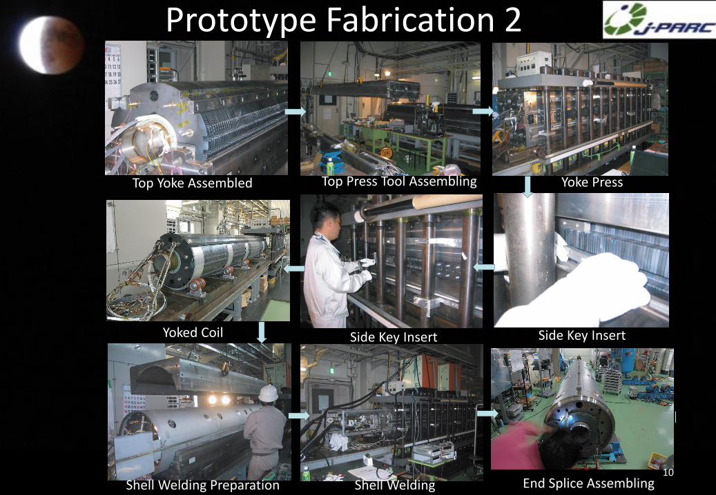
Prototype Fabrication 2
Yoke PressTop Press Tool AssemblingTop Yoke Assembled
Yoked Coil Side Key Insert Side Key Insert
Shell Welding Preparation End Splice AssemblingShell Welding

Prototype Completion and Testing
Installation into cryostat
Prototype Completed by Jan. 2005
Cold test in vertical Cryostat in March 2005
Iop = 7345 A @ 50 GeV (and Imax = 7,700 A)
reached with no quench, on March 4, 2005
Participating members
I = 7435 A, 7700 A
Record of
Excitation
current
Measurement Computation
Current (A) 7460 7345
B1 (T•m) 8.906 8.712
B2 (T•m) 3.127 3.120
B3 (T•m) -220.6*10-4 -293.6*10-4
B4 (T•m) -5.9*10-4 -20.1*10-4
B5 (T•m) -51.9*10-4 -30.6*10-4
B6 (T•m) -75.2*10-4 -62.8 *10-4
B7 (T•m) -44.6*10-4 -20.9*10-4
B8 (T•m) -74.5*10-4 -32.0*10-4
B9 (T•m) -79.9*10-4 -73.4*10-4
B10 (T•m) -13.8*10-4 -0.3*10-4
Field Measurement Result
Participating member
Field Quality Meets Optics RequirementsNo feedback to the design
12
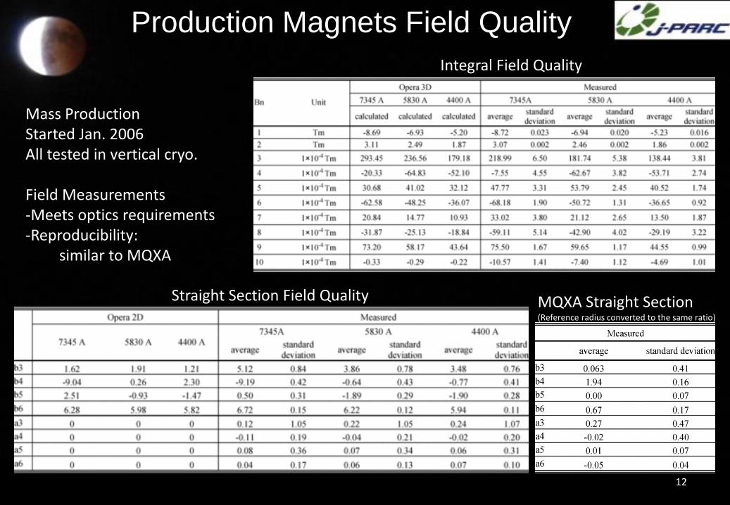
Production Magnets Field Quality
Integral Field Quality
Straight Section Field Quality MQXA Straight Section(Reference radius converted to the same ratio)
Mass ProductionStarted Jan. 2006All tested in vertical cryo.
Field Measurements-Meets optics requirements-Reproducibility:
similar to MQXA

Doublet Cryostat
• Cryostat Design
– Common baseline: LHC cryostat: Reduce Cost and Risk
– Common Parts advantage of LHC mass production (also Strong CERN support)
Cold Diode Support Post Support Post
Connecting Sleeve
Vacuum Vessel

Beam Line Configuration
• 14 Doublets
• 13 Interconnets
– 5 Beam Monitors
– 3 Steering Magnets
– 4 Quench Valves
Doublet
Exp.J.

J-PARC Neutrino Beam Line
Cryogenics Building
SC Magnet Beam Line Cryogenic System
Construction Completed in Dec. 2008Hardware Commissioning Jan~Mar. 2009

Operation Statistics
16
First beam in Apr. 2009Beam commissioning in 2009Physics Run starts Jan. 2010
Proton beam profile monitors
OTR detector just in front of target
Muon monitor profile

Statistics until the earthquake
17
• Allocated Time:2430hr
• NU trouble: 107hr (4.4%)
• SC trouble
– 4 troubles• Beam Induced Quench: 1
• Interlock: 3
– Total time: 14hr (0.6%)
0
5
10
15
20
25
Tim
e [
h]
Acc. tuning, trouble
NU trouble
NU tuning, study
Physics run
Statistics Nov 2010 ~ Mar 2011
T2K PAC Jan. 11
Imperial College/RAL
Dave Wark
(~15.5 kW x 107 s)
3.3 x 10¹⁹
Beam Delivery during 2010a Period (Jan-June 2010)
Total delivered p.o.t.
~ 1/6 planned, but
enough to begin
n measurements.
Statistics Jan-Jun 2010

Beam Induced Quench
• Nov. 28 2010
• Beam hits beam profile monitor frame
18
[4]
Throughout the design and
development, Kakuno and four
experts from Mechanical
Engineering Center and Cryogenic
Science Center at KEK were
challenged by the extremely low
temperature. Superconducting
magnets are kept cool at minus
270 degrees Celsius to keep the
superconducting state. Kakuno's
monitors, sandwiched between
the magnets, need to stay at
minus 150 degrees. When he first
tested his linear guides, the
monitors would not move because
the various components shrank
differently depending on their
materials. "It took three years of
testing and making modifications
to finally get it work," says
Kakuno.
Unlike the profile monitor, the
intensity and position monitors do
not interact with the beam directly.
For the intensity monitor, Dr.
Masahiro Shibata of KEK, the
monitor group leader, uses a
current transformer (CT) to
measure the magnetic field
produced by the beams passing
through. Dr. Nicholas Hastings of
KEK designed the beam position
monitors adopting an electro-
static monitor design. The beam
loss monitors are completely out
of the way sitting well below the
magnets simply to catch any
radiation coming from the
beamline.
The monitor team has finished
tests, installation, and calibration.
During the commissioning, the team
successfully extracted beautiful plots of
secondary electron distribution and beam
current from the single-bunch beams. Now
they are trying to understand the beams by
analyzing the data and making modifications to
their monitors. "The monitors worked as we
expected," says Hastings, "but we found a
new background issue." When the profile and
position monitors were used at the same
location, it seems that the electrons from the
profile monitors cause background noise in the
position monitor. Hastings is now looking at
the problem from two sides; namely, the data
analysis side and the physical approach. On
the physical side, he has added a solenoid to
ward off unwanted electrons.
Apart from Hastings' work to solve the
background issue, the team members are
working hard to get ready for the next
commissioning. They are developing software
to share their data with the detector teams
both at J-PARC and at Super-Kamiokande.
Also, to test the intensity monitor performance
with the full intensity beam, the team needs to
develop a high current pulser that can produce
up to 200A of current to test the linearity of the
monitor response. They have confirmed the
linearity at currents of up to 90A, and are now
working to develop a pulsar with capacitor that
can operate at very high voltage to pr oduce
the required 200A current.
"The goal of our monitor team is to guide the
beam as precisely as possible during the run,"
says Shibata. The T2K experiment will start
late this year, and collaborators are expecting
the first results next year. The project is
"challenging but interesting," says Hastings
reflecting on many hours in the library , many
simulations and many more electronics, " I am
looking forward to real particle physics
analysis."
Related Link:J-PARCJAEA
Profile monitor sitting between super conducting magnets (top); beam
position monitor for high intensity running (center); and beam intensity
monitor between a superconducting magnet and a normal conducting
magnet (bottom).
HIGH ENERGY ACCELERATOR RESEARCH ORGANIZATION (KEK)
Address : 1-1 Oho, Tsukuba, Ibaraki 305-0801 JAPAN Home : http://www.kek.jp/intra-e/feature/ Mail : [email protected]

Beam Loss and Quench
Quenched Magnets
SCR11-F, SCR12-D
19
SIC10
D-mag F-mag D-mag
SIC10 SCR11 SCR12SIC11
F-magBeam
QuenchQuenchBeam
Collision

Recovery from the quench
• Cooling time ~100 min
• No problem for magnet re-excitation
• Beam operation resumed by about 2 hours
0
500
1000
1500
2000
2500
3000
3500
4000
4500
5000
4
5
6
7
8
9
10
10 20 30 40 50 60 70 80 90 100
P/S c
urre
nt (A
)
Tem
pera
ture
(K)
Time (min)
SC-SupplyUnit5-SupplyMD.IA_TCX701MDMD.IA_TCX702MDMD.IA_TCX703MDMD.IA_TCX704MDMD.IA_TCX705MDMD.IA_TCX706MDMD.IA_TCX707MDMD.IA_TCX708MDMD.IA_TCX709MDMD.IA_TCX710MDMD.IA_TCX711MDMD.IA_TCX712MDMD.IA_TCX713MDMD.IA_TCX714MDUnit5-ReturnCLB-ReturnSC出口温度

The Great East Japan Earthquake
Damages and Recovery
J-PARC LINAC

Great East Japan Earthquake
Tsunami invasion map GPS datum points movement
Velocity ResponseAround J-PARC
Peak velocity:~1m/s
Peak acceleration:~8.5m/s2
Integrated Move:~1m Horizontal~0.3m Vertical
J-PARC
Mar. 11 2011 14.46 M9.0

LINAC
Impact on J-PARC
Neutrino Dump
3GeV RCS
No Tsunami invasion into J-PARC
Main Ring
LINAC
River near J-PARC

No damage on LN2 tank No damage on
refrigeration system
Damages on Neutrino Beam Line Cryogenics
Land sank ~ 300mm
Helium tank base sank ~2cm
Base sank~2cm
Sub-tunnel sank ~1cm
No apparent damages on magnet system
Cryogenics: in operationMagnets: not excited

25
Recovery Procedure
Date Event Description
11 Mar Earthquake Minimum safety check
13 Mar Safety Op. Pressure equalization
17 Mar Tunnel Check With handy light and O2monitor
24 Mar Low V Recov. Lights in the tunnel
29 Mar Water Recov.
1 Apr. High V Recov. High voltage electricity
4 Apr. Aircon. Recov. In tunnel
11 Apr. Refrig. Exam. Cold box interior
15 Apr. Mag. Exm. Mag. Cryo. interior
19 Apr. Comp. Exam. Refrig. Main compressor
23 May~1Jun.
System test Cooldown and excitation
Cold Box Interior
Cryo. InteriorSystem health confirmed

2
SC magnet alignment
Displacement and Re-Alignment of Neutrino Beam Line Magnets
5
Arc section H and dR
新しい壁基準座座標で見た設計値からの
ずれ
Preparation section H
アーク部はノンゼロになってしまったが、なめらかな変化 高さはすべて1.47mmにそろえた
AfterEarthquakeWith respectGPS
After Alignment; with respect tunnel Before operation; with respect GPS
May 2011
Aug. 2011
Oct. 2011
Oct.2011Expansion joint
ContinuousMovement ofEast Japan after EQ
27
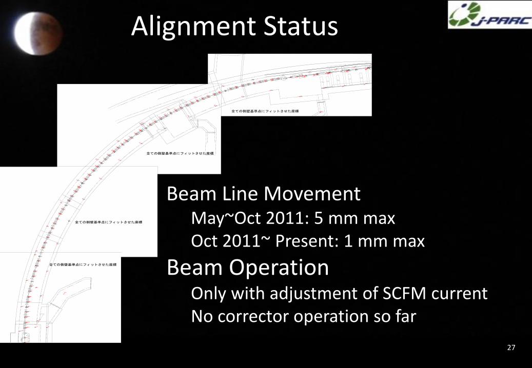
Alignment Status
Beam Line MovementMay~Oct 2011: 5 mm maxOct 2011~ Present: 1 mm max
Beam OperationOnly with adjustment of SCFM currentNo corrector operation so far

Statistics after the earthquake
28
2012 March-JuneNu trouble 4.2% (77 h)*Excluding major trouble by the horn
SC trouble 3.5% (46 h)Mostly false trigger by interlock system
>trouble on the logic boards: Fixed summer 2012
No beam stop due to SC trouble
after summer 2012
May 09 May 13 May 17 May 20 May 24 May 27 May 31 Jun 04 Jun 07 Jun 11 Jun 14 Jun 18 Jun 22 Jun 25 Jun 29 Jul 02
[PO
T]
0.0
0.1
0.2
0.3
0.4
0.5
0.6
0.7
0.8
2110´
2014/7/2 14:50Expected : 1.2498e+21
Achieved : 7.4921e+20 (59.9%)
Integrated Delivered POT
May 09 May 13 May 17 May 20 May 24 May 27 May 31 Jun 04 Jun 07 Jun 11 Jun 14 Jun 18 Jun 22 Jun 25 Jun 29 Jul 02
[PO
T/d
ay]
0
1
2
3
4
5
1810´
240kW, 85% eff. assumed)®Expected (Solid: 100kW
240kW, 90% eff. assumed)® (Dashed: 100kW
240kW, 95% eff. assumed)® (Dotted: 100kW
Achieved : Max 3.787e+18
Delivered POT per day
May 15 May 22 May 29 Jun 05 Jun 12 Jun 19 Jun 26 Jul 03
[min
]
0.0
0.2
0.4
0.6
0.8
1.0
1.2
1.4
1.6
310´
MR user beam (827H) NU Physics Run (530H,64.2%) NU tuning/study (108H,13.1%)NU Trouble (25H,3.1%) Acc. Trouble (152H,18.4%) Acc. Tuning/Study (10H,1.3%)
Run Time Usage
2012 Mar – 2012 Jun
2012 Oct – 2013 May
2014 May – 2014 Jun
200kW max
240kW max
220kW max
J-PARCShutdownDue toHadronAccident

Achievements
29
15th June 2011Indication of Electron Neutrino AppearanceFrom data collected before March 11, 2011http://legacy.kek.jp/intra-e/press/2011/J-PARC_T2Kneutrino.htmlhttp://www.j-parc.jp/hypermail/news-l.2011/0005.html
19th July 2013Discovery of Electron Neutrino AppearanceFrom data collected before May 23, 2013http://legacy.kek.jp/intra-e/press/2013/071921/http://www.j-parc.jp/hypermail/news-l.2013/0004.html

Summary• Operation Statistics
– Very good until the earthquake
• One beam induced quench
– Worsened due after the earthquake
• Fixed summer 2012
– No trouble after Summer 2012
• The Earthquake
– Damage to the system was minimum
– Re-alignment was needed
• Corrector Improvement
– Improve bus cooling and fixed problem
• Bypass Diode Bus Consolidation
– Same implementation as LHC
• Radioactive Material Control
– Temporal radiation control area for refrigerator maintenance

35
Also thank toJ-PARC, KEK, CERN staffsMitsubishi Electric, Toshiba, Furukawa,TNSC, MYCOM, etc…
Acknowledgments