Embed Size (px)
Citation preview
Development and Validation of a Conceptual Design Program for
Unmanned Underwater Vehicles
By
ENS Alexander Walter Laun, USN
Bachelor of Science in Naval Architecture
United States Naval Academy, 2011
SUBMITTED TO THE DEPARTMENT OF MECHANICAL ENGINEERING INPARTIAL FULFILLMENT OF THE REQUIREMENTS FOR THE DEGREES OF
MASTER OF SCIENCE IN NAVAL ARCHITECTURE AND MARINE ENGINEERING
ANDMASTER OF SCIENCE IN OCEAN ENGINEERING
AT THE
MASSACHUSETTS INSTITUTE OF TECHNOLOGY
June 2013
OF TECHNOLOGY
JUN 2 5 2013
LIBRARIES
0 2013 Alexander Walter Laun. All rights reserved.
The author hereby grants to MIT and The Charles Stark Draper Laboratory, Inc. permission to reproduce
and to distribute publicly paper and electronic copies of this thesis document in whole or in part in any
medium now known or hereafter created.
Signature of Author
Department of Mechanical Engineering
May 10, 2013
Certified ByDr. Michael Ricard
Distinguished Member of the Technical Staff, The Charles Stark Draper Laboratory
Technical Supervisor
Certified By _____________ ___________
CDR Jerod Ketcham, USN
Associate Professor of the Practice r Construction and Engineering
/2 4 vsis 'pesor
Accepted ByProfessor David Hardt
Chairman, Departmental Committee on Graduate Students
Department of Mechanical Engineering
Development and Validation of a Conceptual Design Program forUnmanned Underwater Vehicles
By
ENS Alexander Walter Lauin, USN
Submitted to the Department of Mechanical Engineering on May 10, 2013 in
Partial Fulfillment of the Requirements for the Degrees of
Master of Science in Naval Architecture and Marine Engineering and
Master of Science in Ocean Engineering
Abstract
With a renewed focus on the Asia-Pacific region, the United States Navy will increasingly rely
on high-endurance unmanned underwater vehicles (UUVs) to support successful operations in a
challenging threat environment. Undoubtedly, this naval strategy will necessitate versatile UUVsystems that fulfill a broad spectrum of customer-generated requirements.
This thesis presents a unique approach to the conceptual design process for UUVs, thereby
allowing strategic decision-makers to rapidly explore a given design space. The proposed
MA TLAB-based conceptual design program features five primary modules: a mission module, a
hull module, a resistance module, a battery module, and a pressure vessel module. The final
concept design results from an iterative process that considers the displacement, interior volume,and exterior volume of the total UUV system.
To validate the proposed design algorithm, the author applied the best practices of modern naval
architecture, marine engineering, ocean engineering, systems engineering, and submersible
design. Model test data and computational fluid dynamics (CFD) software were used to validate
the empirical equations selected for the resistance module. The pressure vessel module,
including a genetic algorithm to generate viable scantlings, was validated by a consideration of
manually optimized pressure vessel designs. Ultimately, this thesis demonstrates the sufficiency,
reliability, and versatility of the proposed conceptual design program for UUVs.
Technical Supervisor: Dr. Michael Ricard
Title: Distinguished Member of the Technical Staff, The Charles Stark Draper Laboratory
Thesis Supervisor: CDR Jerod Ketcham, USN
Title: Associate Professor of the Practice, Naval Construction and Engineering
Page 2
Acknowledgments
The author would like to acknowledge the extensive support from Dr. Michael Ricard and CDR
Jerod Ketcham. Dr. Ricard served as the primary technical supervisor for this thesis, providingcountless hours of advice, assistance, and friendship. CDR Ketcham served as the primary thesis
supervisor for this publication, providing extensive professional mentorship and superior insightsabout the submarine design process. The author remains eternally grateful for the true kindnessand patience demonstrated by these two individuals.
The author would also like to thank the many technical advisors, naval architects, and engineersat The Charles Stark Draper Laboratory who provided endless guidance for this thesis, includingMr. Joel Parry, Mr. Glenn Ogrodnik, Mr. Naren Chhabra, and Mr. Pete Sebelius. These individualscontinually challenged the author to improve the proposed design algorithm and ensured that the
best practices of modem naval architecture were always considered. At MIT, the author remains
thankful for the support and mentorship provided by CDR Pete Small throughout the first year of
this thesis, as well as the friendships developed with many of the officers in the Naval Constructionand Engineering (2N) Program.
Additional support, motivation, and humor were provided by the roommates of the author, to whomthe author remains indebted for making this two-year experience truly enjoyable and worthwhile.
Ultimately, the author would like to thank the United States Navy for allowing a newly commis-sioned naval officer to pursue advanced graduate studies at MIT. Participation in the ImmediateGraduate Education Program (IGEP) allowed the author to explore many unique academic inter-
ests, including a true passion for naval architecture developed at the United States Naval Academy.The author remains humbled by his experiences at MIT (as a Draper Laboratory Fellow) and in-spired to support future technical design efforts within the United States Navy.
Relevant questions and comments about this thesis (or any subject matter contained herein) maybe forwarded directly to the author ([email protected]).
Page 3
Contents
Abstract 2
Acknowledgments 3
List of Figures 6
List of Tables 7
List of Symbols and Abbreviations 8
General Symbols . . . . . . . . . . . . . . . . . . . . . . . . . . . .. . . . - . . . 8
Greek Symbols . . . . . . . . . . . . . . . . . . . . . . . . . .. - . . . - - - - . 14
General Abbreviations . . . . . . . . . . . . . . . . . . . . . . . . .. . .. - . . . . 16
1 Introduction 19
1.1 Strategic Perspective . . . . . . . . . . . . . . . . . . . . .. . . .. - - - - - . 19
1.2 UUV Policy and Operations . . . . . . . . . . . . . . . . . . . . . . . . . . . . . 20
1.3 Modem UUV Systems and Technology . . . . . . . . . . . . . . . . . . . . . . . 21
1.4 Thesis Motivation and Design Philosophy . . . . . . . . . . . . . . . . . . . . . . 23
2 Program Development 25
2.1 Generic Conceptual Design Process . . . . . . . . . . . . . . . . . . . . . .. . . 25
2.2 Generic Submersible Design Process . . . . . . . . . . . . . . . . . . . . . . . . . 26
2.3 Program Structure and Functionality . . . . . . . . . . . . . . . . . . . . . . . .. 28
2.3.1 Mission Module . . . . . . . . . . . . . . . . . . . . . .. . . - - - . 29
2.3.2 Hull Module . . . . . . . . . . . . . . . . . . . . . . . .. . - . .. . . 31
2.3.3 Resistance Module . . . . . . . . . . . . . . . . . . . . . . . . . - . . 33
2.3.4 Battery Module . . . . . . . . . . . . . . . . . . . . . . . . . . .. . . . . 39
2.3.5 Pressure Vessel Module . . . . . . . . . . . . . . . . . . . . . . . . . . . 41
2.3.6 Balance and Optimization Routine . . . . . . . . . . . . . . . . . . . . . .. 50
Page 4
3 Program Validation 55
3.1 Parametric Data and Design Assumptions . . . . . . . . . . . . . . . . . . . . . . 55
3.2 Resistance Module Validation . . . . . . . . . . . . . . . . . . . . . . . . . . . . 57
3.3 Pressure Vessel Module Validation . . . . . . . . . . . . . . . . . . . . . . . . . . 63
4 Concept Design Example 65
5 Conclusion 68
5.1 Thesis Summ ary . . . . . . . . . . . . . . . . . . . . . . . . . . . . . . . . . . . 68
5.2 Recommendations and Future Research Efforts . . . . . . . . . . . . . . . . . . . 68
Appendix A: Alternative Design Options 70
References 74
Page 5
List of Figures
1
2
3
4
5
6
7
8
9
10
11
12
13
14
15
16
17
Design Spiral for a Naval Warship . . . . . . . . .
Simplified Design Spiral for a Submarine . . . . .
Basic Design Program Structure . . . . . . . . . .
Major UUV Systems and Components . . . . . . .
Standard Jackson Hull-Form Geometry . . . . . .
Standard Pressure Vessel Design . . . . . . . . . .
Primary Pressure Vessel Failure Modes . . . . . .
Primary Pressure Vessel Scantlings . . . . . . . . .
Basic Structure of the Pressure Vessel Module . . .
Basic UUV Volume Allocation . . . . . . . . . . .
Length-to-Diameter Ratio Values for Existing UUV
Parametric Description of the Series 58 Model 4165 Hull-Form . . . . .
Parametric Description of the DARPA SUBOFF Model 5470 Hull-Form
CFD Geometry for the Series 58 Model 4165 Hull-Form . . . . . . . .
ANSYS CFX Flow Profile for the Series 58 Model 4165 Hull-Form . . .
Three-Dimensional Depiction of the Concept Design Example . . . . .
Automated Iteration of the Concept Design Example . . . . . . . . . .
18 Evolutionary Progression of the MATLAB-Based Genetic Algorithm 67
Page 6
Designs
. . . . . . 25
. . . . . . 26
. . . . . . 29
. . . . . . 30
. . . . . . 31
. . . . . . 41
. . . . . . 42
. . . . . . 43
. . . . . . 49
. . . . . . 53
. . . . . . 56
. . . . . . 58
. . . . . . 59
. . . . . . 61
. . . . . . 62
. . . . . . 65
. . . . . . 66
List of Tables
Standard UUV Classification . . . . . . . . . . . .
Standard ESWBS for a Marine Vehicle . . . . . .
DoD WBS for an Unmanned Maritime System
Common UUV Battery Technology Data . . . . .
Primary Genetic Algorithm Constraints . . . . .
ESWBS Summary for the UUV Concept Design.
Primary Hull Geometry Variables . . . . . . . .
Parametric Values for the UUV Hull Geometry .
Comparative Analysis of Relevant Resistance Data
. . . . . . . . . . . . . . . . . 2 2
. . . . . . . . . . . . . . . . . 27
. . . . . . . . . . . . . . . .. 2 7
. . . . . . . . . . . . . . . . . 4 0
. . . . . . . . . . . . . . . . . 4 8
. . . . . . . . . . . . . . . . . 5 0
. . . . . . . . . . . . . . . . . 5 5
. . . . . . . . . . . . . . . . . 5 7
. . . . . . . . . . . . . . . . . 60
1
2
3
4
5
6
7
8
9
10
11
12
61
63
64
Page 7
Comparative Analysis of CFD Data for the Series 58 Model 4165 Hull-Form
Comparative Analysis of CFD Data for Four Generic UUV Models . . . . . .
Comparative Analysis of Pressure Vessel Weight-to-Displacement Ratio Data
List of Symbols and Abbreviations
General Symbols
A Maximum Cross-Sectional Area
ALA THuLL Lateral Area of Entire Submersible
ALATREQ Total Required Control Surface Lateral Area
AIATSURF Lateral Area of Each Control Surface
a Length of Forward Hull-Section (Myring)
BALEXT Exterior Volume Balance Parameter
BALINT Interior Volume Balance Parameter
BALw Vehicle Weight Balance Parameter
b Length of Parallel Mid-Body (Myring)
bF Pressure Vessel Stiffener Flange Width
CA Roughness / Correlation Allowance
CAFT Aft Hull-Section Length Factor
CAPP Appendage Resistance Coefficient
cc Surface Curvature Coefficient
CE Eddy Resistance Coefficient
CF Coefficient of Frictional Resistance
CFORM Form Resistance Coefficient
CFWD Forward Hull-Section Length Factor
CP Prismatic Coefficient
CR Coefficient of Residual Resistance
Cygw Non-Dimensional Propeller Design Term (NSWC)
CT Coefficient of Total Resistance
CT, Coefficient of Total Resistance (Gillmer and Johnson Method)
CT5 Coefficient of Total Resistance (Chhabra Method)
CT7 Coefficient of Total Resistance (Hoerner Wetted Surface-Area Method)
Page 8
CT9 Coefficient of Total Resistance (Jackson Curve-Fit Method)
CT2 Coefficient of Total Resistance (Martz Method)
Cy Coefficient of Viscous Resistance
Cw Coefficient of Wave-Making Resistance
Cl Flange Width-to-Thickness Ratio (Gorman Method)
c2 Web Height-to-Thickness Ratio (Gorman Method)
C3 Non-Dimensional Term (Gorman Method)
C4 Non-Dimensional Term (Gorman Method)
C5 Non-Dimensional Term (Gorman Method)
D Hull Diameter
Di Track Distance (Single Track)
DpRop Maximum Propeller Diameter
Dpv Maximum (Outer) Diameter of Pressure Vessel
d Maximum Hull-Form Diameter (Myring)
EAR Expanded-Area Ratio
EDBATT Energy Density of Selected Battery Technology
EH Vehicle Hotel Load
EHi Incremental Hotel Load (Single Track)
EHP Effective Horsepower
EMAT Modulus of Elasticity
Ep Propulsive Load
ET Total Vehicle Energy
Er, Incremental Vehicle Energy (Single Track)
Fn Froude Number
G Bryant Buckling Factor
g Acceleration of Gravity
h92 Maximum Limiting Depth for Frame Yield (92)
h92A Maximum Limiting Depth for Mid-Bay Yield (92A)
Page 9
h92AMOD Maximum Limiting Depth for Mid-Bay Yield (92A Modified)
hBEND Maximum Limiting Depth for Frame Hoop Stress (Bending)
hBRYANT Maximum Limiting Depth for General Instability (Bryant)
hCOMP Maximum Limiting Depth for Frame Hoop Stress (Compressive)
hLOBAR Maximum Limiting Depth for Lobar Buckling
hop Maximum Operating Depth
hw Pressure Vessel Stiffener Web Height
is Moment-of-Inertia of Combined (Stiffener and Shell) Section
J Advance Coefficient
K Non-Dimensional Hull-Form Parameter
KT Thrust Coefficient
KTO Thrust Coefficient (Specific Operating Point)
KQ Torque Coefficient
L Hull Length
LA Aft-Body Length
Lc Pressure Vessel Length Between Bulkheads
LF Fore-Body Length
LM Parallel Mid-Body Length
LMPV Pressure Vessel Parallel Mid-Body Length
Ls Pressure Vessel Frame (Stiffener) Spacing
LTAIL Length of Aft Hull-Section (Myring)
L Length-to-Diameter Ratio
m Non-Dimensional Buckling Factor
n Forward Hull-Section Curvature Index (Myring)
nA Aft Hull-Section Curvature Factor
nB Number of Circumferential Buckling Waves
nF Forward Hull-Section Curvature Factor
nr Total Number of User-Defined Tracks
Page 10
PC Propulsive Coefficient
PCR Critical Inter-Stiffener Pressure
PF Packing Factor
PF20 1 Packing Factor for Primary Vehicle Propulsion System
PF30 1 Packing Factor for Battery System
PF401 Packing Factor for GNC System
PF40 2 Packing Factor for Vehicle Controller
PF40 3 Packing Factor for Autonomy Controller
PF40 4 Packing Factor for Payload Controller
PF4 05 Packing Factor for INS / DVL / GPS System
PF406 Packing Factor for Pressure Sensor
PF407 Packing Factor for Forward-Looking Sonar
PF408 Packing Factor for Side-Looking Sonar
PF409 Packing Factor for Synthetic Aperture Sonar
PF501 Packing Factor for Auxiliary Structures
PF502 Packing Factor for Auxiliary Cabling
PF503 Packing Factor for Primary Ballast System
PF504 Packing Factor for Variable Ballast System
PF601 Packing Factor for Hull Quieting Material
PHi Incremental Hotel Power (Single Track)
Pop External Pressure
Pitch-to-Diameter RatioQ(
0 Algebraic Term (Gorman Method)
f? Algebraic Term (Gorman Method)
RAPP Total Appendage Resistance
Rn Reynolds Number
RT Total Ship Resistance
RTALGORIM Total Hull-Form Resistance (Design Algorithm Calculation)
Page 11
RTTEST Total Hull-Form Resistance (Model Test Data)
RTTOTAL Total Bare-Hull Resistance
rNOSE Radius of Forward Hull-Section (Myring)
rTAIL Radius of Aft Hull-Section (Myring)
S Wetted Surface-Area
5 Algebraic Term (Gorman Method)
SAPP Wetted Surface-Area of All Appendages
SEBATT Specific Energy of Selected Battery Technology
SFB Design Factor for General Instability (Gorman Method)
SFL Design Factor for Lobar Buckling (Gorman Method)
SFy Design Factor for Shell Membrane Yield (Gorman Method)
SHP Shaft Horsepower
Non-Dimensional Propeller Design Term (NSWC)
7' Algebraic Term (Gorman Method)
Ti Operating Time (Single Track)
t Thrust Deduction Fraction
T Optimum Thickness Value (Gorman Method)
t Non-Dimensional Propeller Design Term (NSWC)
tENV Nominal Envelope Shell Thickness
tF Pressure Vessel Stiffener Flange Thickness
tGORMAN Thickness Design Variable (Gorman Method)
tp Pressure Vessel Shell (Plating) Thickness
tPMIN Minimum Shell Thickness
tw Pressure Vessel Stiffener Web Thickness
U Algebraic Term (Gorman Method)
U Non-Dimensional Propeller Design Term (NSWC)
V Ship Speed
Vi Operating Speed (Single Track)
Page 12
v Non-Dimensional Propeller Design Term (NSWC)
WBATT Battery Weight
WFULL Total Full-Load Weight of UUV
WMAR Design Margin Weight
W101 Weight of Pressure Vessel
W201 Weight of Primary Vehicle Propulsion System
W301 Weight of Battery System
W40 1 Weight of GNC System
W402 Weight of Vehicle Controller
W403 Weight of Autonomy Controller
W4 04 Weight of Payload Controller
W405 Weight of INS / DVL / GPS System
W406 Weight of Pressure Sensor
W4o7 Weight of Forward-Looking Sonar
W40 8 Weight of Side-Looking Sonar
W40 9 Weight of Synthetic Aperture Sonar
W501 Weight of Auxiliary Structures
W502 Weight of Auxiliary Cabling
W503 Weight of Primary Ballast System
W504 Weight of Variable Ballast System
W6 01 Weight of Hull Quieting Material
W701 Weight of Modular Mission Payload
w Wake Fraction
x Axial Coordinate (Myring)
xA Local Distance (Aft-Body)
XF Local Distance (Fore-Body)
YA Radial Offset (Aft-Body)
YF Radial Offset (Fore-Body)
Z Number of Propeller Blades
Page 13
Greek Symbols
a Tail Semi-Angle (Myring)
AFULLAVAIL Total Available Vessel Displacement
3% Calculated Percent Difference Value
77HULL Hull Efficiency
?1PROP Propeller Efficiency
77RR Relative Rotative Efficiency
VBATT Battery Volume
VE Envelope Volume
VEXTAVAIL Total Usable Exterior Volume
VEXTREQ Total Required External Volume
VFF Allocated Free-Flood Volume
VINTAVAIL Total Usable Interior Volume
VINTREQ Total Required Internal Volume
VLEAD Allocated Lead Volume
VMAR Allocated Margin Volume
VRES Allocated Reserve Volume
Vioi Volume of Pressure Vessel
V20 1 Volume of Primary Vehicle Propulsion System
V301 Volume of Battery System
V401 Volume of GNC System
V402 Volume of Vehicle Controller
V403 Volume of Autonomy Controller
V404 Volume of Payload Controller
V405 Volume of INS / DVL / GPS System
V406 Volume of Pressure Sensor
V407 Volume of Forward-Looking Sonar
V40 8 Volume of Side-Looking Sonar
Page 14
V409 Volume of Synthetic Aperture Sonar
V50 1 Volume of Auxiliary Structures
V502 Volume of Auxiliary Cabling
V50 3 Volume of Primary Ballast System
V504 Volume of Variable Ballast System
V601 Volume of Hull Quieting Material
V701 Volume of Modular Mission Payload
v Kinematic Viscosity of Water
VMAT Poisson Ratio
p Mass-Density of Water
PMAT Material Density
aBEND Frame Bending Stress
OTOTAL Total Frame Stress
(Ty Yield Strength
Page 15
General Abbreviations
A2/AD Anti-Access / Area-Denial
ABS American Bureau of Shipping
AoA Analysis-of-Alternatives
ASSET Advanced Ship and Submarine Evaluation Tool
ASW Anti-Submarine Warfare
AUV Autonomous Underwater Vehicle
CFD Computational Fluid Dynamics
CN3 Communication / Navigation Network Node
CSDL The Charles Stark Draper Laboratory
DARPA Defense Advanced Research Projects Agency
DoD Department of Defense
DoN Department of the Navy
DTIC Defense Technical Information Center
DTMB David Taylor Model Basin
DVL Doppler Velocity Log
ELINT Electronic Intelligence
EOD Explosive Ordnance Disposal
ESWBS Expanded Ship Work Breakdown Structure
FEA Finite-Element Analysis
FLS Forward-Looking Sonar
FoS Factor-of-Safety
FY Fiscal Year
FYDP Future Years Defense Program
GA Genetic Algorithm
GL Germanischer Lloyd
GNC Guidance, Navigation, and Control
GPS Global Positioning System
Page 16
GUI Graphic User Interface
HWV Heavy Weight Vehicle
HY High-Yield
ID Inspection / Identification
IMINT Imagery Intelligence
INS Inertial Navigation System
10 Information Operations
ISR Intelligence, Surveillance, and Reconnaissance
ITTC International Towing Tank Conference
JCIDS Joint Capabilities Integration and Development System
LBS Littoral Battlespace Sensor
LCS Littoral Combat Ship
LDUUV Large Displacement Unmanned Undersea Vehicle
LWV Light Weight Vehicle
L/D Length-to-Diameter Ratio
MASINT Measurement and Signature Intelligence
MCM Mine Countermeasures
MIT Massachusetts Institute of Technology
MK Mark
NAVSEA Naval Sea Systems Command
NPS Naval Postgraduate School
NSWC Naval Surface Warfare Center
NSWCCD Naval Surface Warfare Center, Carderock Division
NUWC Naval Undersea Warfare Center
ONR Office of Naval Research
PLAN People's Liberation Army Navy
PMB Parallel Mid-Body
PPBE Planning, Programming, Budgeting, and Execution
Page 17
PRC People's Republic of China
RDT&E Research, Development, Test, and Evaluation
ROV Remotely-Operated Vehicle
SAS Synthetic Aperture Sonar
SIGINT Signal Intelligence
SLS Side-Looking Sonar
SOF Special Operations Forces
SPAWAR Space and Naval Warfare Systems Command
TCS Time Critical Strike
UAV Unmanned Aerial Vehicle
UMCM Underwater Mine Countermeasures
UMS Unmanned Maritime Systems
USMC United States Marine Corps
USN United States Navy
USNA United States Naval Academy
USV Unmanned Surface Vehicle
UUV Unmanned Underwater Vehicle
WBS Work Breakdown Structure
WMD Weapon of Mass Destruction
WSA Wetted Surface-Area
W/D Weight-to-Displacement Ratio
Page 18
1 Introduction
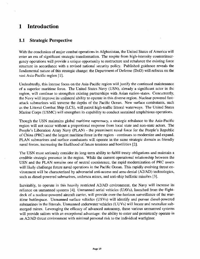
1.1 Strategic Perspective
With the conclusion of major combat operations in Afghanistan, the United States of America willenter an era of significant strategic transformation. The respite from high-intensity counterinsur-gency operations will provide a unique opportunity to restructure and rebalance the existing forcestructure in accordance with a revised national security policy. Published guidance reveals thefundamental nature of this strategic change: the Department of Defense (DoD) will refocus on thevast Asia-Pacific region [1].
Undoubtedly, this intense focus on the Asia-Pacific region will justify the continued maintenanceof a superior maritime force. The United States Navy (USN), already a significant actor in theregion, will continue to strengthen existing partnerships with Asian nation-states. Concurrently,the Navy will improve its unilateral ability to operate in this diverse region. Nuclear-powered fast-attack submarines will traverse the depths of the Pacific Ocean. New surface combatants, suchas the Littoral Combat Ship (LCS), will patrol high-traffic littoral waterways. The United StatesMarine Corps (USMC) will strengthen its capability to conduct sustained amphibious operations.
Though the USN maintains global maritime supremacy, a strategic rebalance to the Asia-Pacificregion will not occur without a proportional response from local state and non-state actors. ThePeople's Liberation Army Navy (PLAN) - the preeminent naval force for the People's Republicof China (PRC) and the largest maritime force in the region - continues to modernize and expand.PLAN submarines and surface combatants will operate in the same strategic domain as friendlynaval forces, increasing the likelihood of future tensions and hostilities [2].
The USN must seriously consider its long-term ability to fulfill treaty obligations and maintain acredible strategic presence in the region. While the current operational relationship between theUSN and the PLAN remains one of neutral coexistence, the rapid modernization of PRC assetswill likely challenge future naval operations in the Pacific Ocean. This rapidly evolving threat en-vironment will be characterized by adversarial anti-access and area-denial (A2/AD) technologies,such as diesel-powered submarines, undersea mines, and anti-ship ballistic missiles [3].
Inevitably, to operate in this heavily restricted A2/AD environment, the Navy will increase itsreliance on unmanned systems [4]. Unmanned aerial vehicles (UAVs), launched from the flight-deck of a nuclear-powered aircraft carrier, will provide over-the-horizon surveillance of the mar-itime battlespace. Unmanned surface vehicles (USVs) will identify and pursue diesel-poweredsubmarines in the littorals. Unmanned underwater vehicles (UUVs) will locate and neutralize sub-merged mines. Leveraging the efficacy of advanced autonomy, these various unmanned systemswill provide sailors with an exceptional advantage: the ability to enter and persistently operate inan A2/AD threat environment with minimal personal risk to the individual warfighter.
Page 19
1.2 UUV Policy and Operations
For decades, the Navy has considered the utility and versatility of unmanned underwater vehi-cle (UUV) technology. The increasing mention of UUVs in published naval strategy represents apositive change to modem national security policy. Most significantly, the Unmanned UnderseaVehicle Master Plan solidified the strategic and operational framework for all Navy UUV develop-ment efforts.
First published in 2000 (and subsequently updated in 2004), the UUV Master Plan representsa collaborative attempt to guide the long-term procurement of UUVs, with a specific focus onoperational mission-areas. As prioritized and detailed within this document, UUVs are expectedto support the following Fleet efforts [5]:
1. Intelligence, Surveillance, and Reconnaissance (ISR). For a typical ISR mission, the UUVcollects diverse tactical data with a variety of onboard sensors. Such data includes signalintelligence (SIGINT), electronic intelligence (ELINT), measurement and signature intelli-gence (MASINT), imagery intelligence (IMINT), and environmental information. The UUVis well adapted for collaborative, persistent, and clandestine operations, including naval op-erations in the littorals.
2. Mine Countermeasures (MCM). For a typical MCM mission, the UUV detects, identifies,and neutralizes undersea mine threats. Such actions support USMC amphibious operationsand near-shore Fleet operations.
3. Anti-Submarine Warfare (ASW). For a typical ASW mission, the UUV detects and pur-sues hostile submarines. Via lethal and non-lethal systems, the UUV can provide sufficientprotection for Fleet assets operating in a contested maritime battlespace.
4. Inspection / Identification (ID). For a typical ID mission, the UUV conducts underwaterhull inspections. Such inspections serve to identify unexploded ordnance and support Ex-plosive Ordnance Disposal (EOD) technicians.
5. Oceanography. For a typical oceanography mission, the UUV collects environmental datawith a variety of onboard sensors. Such data includes information about local bathymetry,water temperature, and water salinity.
6. Communication / Navigation Network Node (CN3). For a typical CN3 mission, the UUVserves as a "critical communication and navigation link" between a variety of Fleet plat-forms. Notably, the UUV can serve as a global positioning system (GPS) relay for otherundersea systems.
7. Payload Delivery. For a typical payload delivery mission, the UUV provides "clandestinesupply and support" for a variety of naval operations. The UUV can support Special Opera-tions Forces (SOF), deploy undersea sensors, and pre-position various combat systems.
Page 20
8. Information Operations (IO). For a typical 10 mission, the UUV serves as an advancedcomputer interface. The UUV can be used for offensive and defensive cyber warfare opera-tions, as well as submarine training operations.
9. Time Critical Strike (TCS). For a typical TCS mission, the UUV clandestinely deliversand deploys a given weapon system. The UUV is well adapted for "forward deployment,"leveraging its stealth to eliminate a threat from a near-target location.
As described, UUVs are highly versatile systems that effectively support a multitude of Fleetmission-areas. The UUV Master Plan provides a basic framework for the development of thesesystems, but the document omits a variety of relevant programmatic factors, including actual Fleetdemand for UUVs, alternative options for all mission-areas, and the expected costs for these uniqueunmanned systems [6].
To better define the expectations for unmanned systems, the DoD recently released the UnmannedSystems Integrated Roadmap. Within this publication, UUVs and USVs are collectively catego-rized as unmanned maritime systems (UMS) [7]. Addressing some of the criticisms of the UUVMaster Plan, the Unmanned Systems Integrated Roadmap redefines UMS "priority missions" asMCM, ASW, maritime domain awareness, and maritime security. Though the true extent of thesemission-areas remains relatively broad, the Unmanned Systems Integrated Roadmap provides arealistic operational framework for the Fleet-wide integration of UUVs.
Evidently, the design and development of UUVs remains intricately related to broader naval policy[8]. Successful UUV development will require improved integration with the existing DoD acqui-sition framework, including the Joint Capabilities Integration and Development System (JCIDS)and the Planning, Programming, Budgeting, and Execution (PPBE) process [7]. Though this thesisfocuses on the technical aspects of UUV development, the modern UUV design engineer can bene-fit from a basic understanding of emerging naval threats, the mission-centric nature of future UUVdesigns, and the structure of the existing developmental environment. Undoubtedly, these diverse,seemingly non-technical perspectives will support the generation of unique, relevant, effective, andaffordable UUV concept designs.
1.3 Modern UUV Systems and Technology
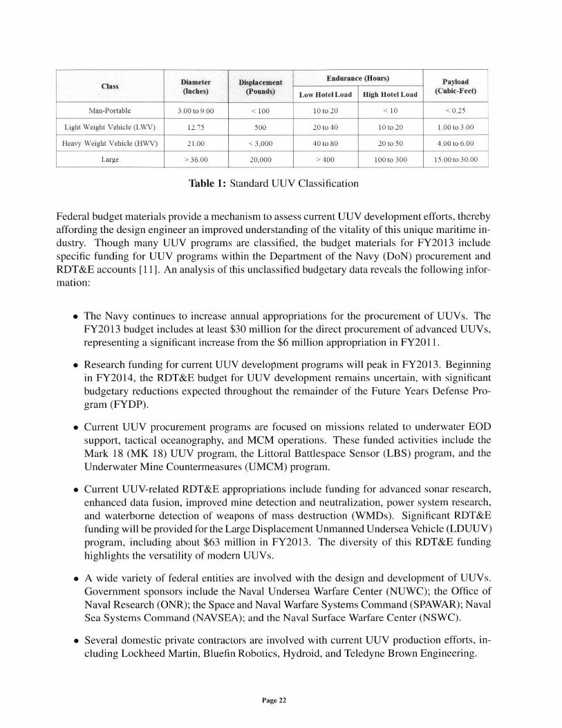
A modern UUV is defined as a "self-propelled submersible whose operation is either fully au-tonomous (pre-programmed or real-time adaptive mission control) or under minimal supervisorycontrol" [9]. Generally, a UUV can be classified as an autonomous underwater vehicle (AUV) ora remotely-operated vehicle (ROV), though some degree of control hybridization may exist [10].As shown in Table 1, the UUV Master Plan provides a classification methodology for modernUUVs that includes vehicle diameter, vehicle displacement, vehicle endurance, and payload vol-ume. The vast majority of modern UUVs are classified as man-portable vehicles, light weightvehicles (LWVs), or heavy weight vehicles (HWVs).
Page 21
Class Diameter Displacement Endurance (Hours) Payload(Inches) (Pounds) Low Hotel Load High Hotel Load (Cubic-Feet)
Man-Portable 3.00 to 9.00 < 100 10 to 20 < 10 < 0.25
Light Weight Vehicle (LWV) 12.75 500 20 to 40 10to20 1.00 to 3.00
Heavy Weight Vehicle (HWV) 21.00 < 3,000 40 to 80 20 to 50 4.00 to 6.00
Large > 36.00 20,000 > 400 100 to 300 15.00 to 30.00
Table 1: Standard UUV Classification
Federal budget materials provide a mechanism to assess current UUV development efforts, therebyaffording the design engineer an improved understanding of the vitality of this unique maritime in-dustry. Though many UUV programs are classified, the budget materials for FY2013 includespecific funding for UUV programs within the Department of the Navy (DoN) procurement andRDT&E accounts [II]. An analysis of this unclassified budgetary data reveals the following infor-mation:
" The Navy continues to increase annual appropriations for the procurement of UUVs. TheFY2013 budget includes at least $30 million for the direct procurement of advanced UUVs,representing a significant increase from the $6 million appropriation in FY2011.
" Research funding for current UUV development programs will peak in FY2013. Beginningin FY2014, the RDT&E budget for UUV development remains uncertain, with significantbudgetary reductions expected throughout the remainder of the Future Years Defense Pro-gram (FYDP).
" Current UUV procurement programs are focused on missions related to underwater EODsupport, tactical oceanography, and MCM operations. These funded activities include theMark 18 (MK 18) UUV program, the Littoral Battlespace Sensor (LBS) program, and theUnderwater Mine Countermeasures (UMCM) program.
" Current UUV-related RDT&E appropriations include funding for advanced sonar research,enhanced data fusion, improved mine detection and neutralization, power system research,and waterborne detection of weapons of mass destruction (WMDs). Significant RDT&Efunding will be provided for the Large Displacement Unmanned Undersea Vehicle (LDUUV)program, including about $63 million in FY2013. The diversity of this RDT&E fundinghighlights the versatility of modern UUVs.
" A wide variety of federal entities are involved with the design and development of UUVs.Government sponsors include the Naval Undersea Warfare Center (NUWC); the Office ofNaval Research (ONR); the Space and Naval Warfare Systems Command (SPAWAR); NavalSea Systems Command (NAVSEA); and the Naval Surface Warfare Center (NSWC).
* Several domestic private contractors are involved with current UUV production efforts, in-cluding Lockheed Martin, Bluefin Robotics, Hydroid, and Teledyne Brown Engineering.
Page 22
As shown, the Navy actively encourages the development and acquisition of modem UUV tech-
nology. The growing focus on larger vehicles will necessitate a well-organized structure to facili-
tate effective technology development. Undoubtedly, to design and procure these high-enduranceUUVs, the Navy will increasingly rely on technical knowledge provided by private entities withdecades of UUV-related experience, such as the primary sponsor of this thesis, The Charles StarkDraper Laboratory (CSDL).
1.4 Thesis Motivation and Design Philosophy
This thesis was motivated by the transformation in national security policy that will likely encour-age the future development of UUVs. DoD utilization of unmanned systems is rapidly increasing,and advanced autonomy is providing greater flexibility to the modem warfighter. With a strategicshift to the Asia-Pacific region, UUVs will serve as an incredibly effective force-multiplier in afiscally-constrained operating environment. Essentially, if properly developed and integrated, aUUV represents a capable, versatile, and affordable solution for a wide variety of modem navaloperations.
This thesis attempts to address two primary shortfalls in the design and development of modemUUV technology: the limited availability of a robust UUV-centric conceptual design process andthe widespread isolation of technical knowledge related to UUV development. An effective con-ceptual design program provides sufficient early-stage information to guide the long-term develop-ment of these unmanned systems. As proven for large-scale submarine acquisition programs, earlyinvestment in the conceptual design process provides down-stream cost savings and mitigates theoverall technical risk of the given program [12]. While the conceptual design process for full-scalesubmarines is relatively well-understood (albeit very specialized), a comparable process for UUVdesign remains underdeveloped.
This thesis consolidates technical design information from a wide variety of sources, includingexperiential knowledge from senior design engineers at CSDL. Unfortunately, within the broadersubmersible design community, such technical information is rarely documented and published.Ultimately, this thesis represents a comprehensive technical study of modem UUV developmentand provides a basic framework to approach the conceptual design process for these unmannedsystems. Extensive guidance was provided by CSDL, and the author fully intends for all informa-tion contained herein to encourage future investigation and consolidation of UUV-related designknowledge.
The technical extent of this thesis was limited to the development of a conceptual design programfor large, high-endurance autonomous underwater vehicles (AUVs). Many existing organizationspossess sufficient skill to produce small AUVs, but the conceptual design space for larger systemsremains relatively unexplored. Per guidance from CSDL, a robust conceptual design program forlarge AUVs will provide the most benefit to the current UUV development community.
To create an acceptable conceptual design program for UUVs, the author adopted a design phi-losophy that focused on the sufficiency, reliability, and versatility of the cumulative program. For
Page 23
a given mission profile, the conceptual design program provides basic information about the di-mensionality and functionality of the outputted vehicle design. A focus on sufficiency ensures thatall major elements of the UUV design process are encapsulated by the program. Programmaticreliability ensures that the resulting design outputs are feasible and accurate. Most significantly,programmatic versatility facilitates the exploration of a large design space and allows for futureimprovement of the comprehensive design tool. Though this thesis represents a single approachto the UUV conceptual design process, the author attempted to apply the best practices of modemnaval architecture, marine engineering, ocean engineering, systems engineering, and submersibledesign.
Page 24
2 Program Development
2.1 Generic Conceptual Design Process
The design of a complex engineering system, such as a UUV, necessitates a robust framework tosuccessfully incorporate all customer-defined requirements. This thesis considers the conceptualdesign phase of UUV development, representing an effort to "clarify [...] the ship's mission andprincipal required performance characteristics, which reflect the desired balance between capabil-ity and affordability" [13]. Ultimately, a successful concept design is achieved by "devising atleast one conceptual system that can be shown to be functionally capable of fulfilling the perceived[operational] need, and by describing it in sufficient detail to persuade decision-makers that it istechnically feasible and can be developed and produced at acceptable cost" [14].
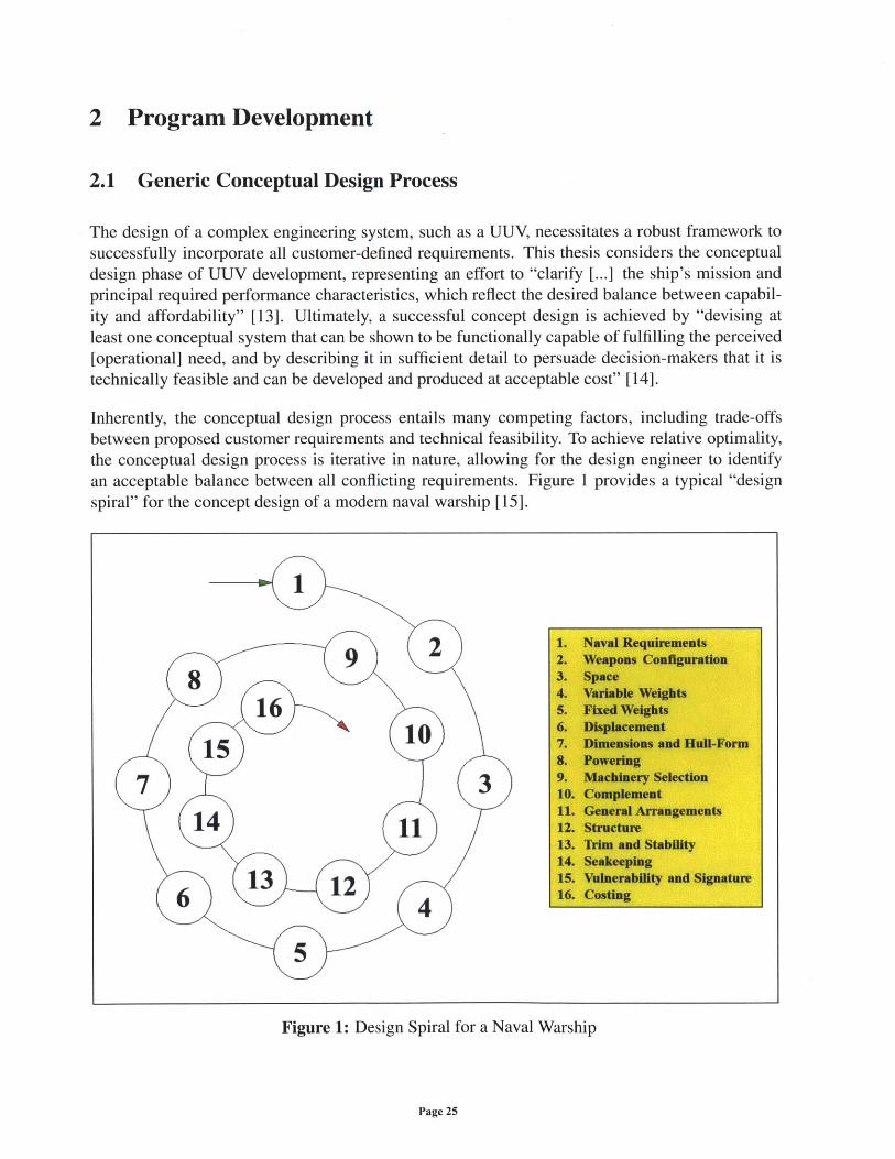
Inherently, the conceptual design process entails many competing factors, including trade-offsbetween proposed customer requirements and technical feasibility. To achieve relative optimality,the conceptual design process is iterative in nature, allowing for the design engineer to identifyan acceptable balance between all conflicting requirements. Figure 1 provides a typical "designspiral" for the concept design of a modern naval warship [15].
Figure 1: Design Spiral for a Naval Warship
Page 25
1. Naval Requirements2. Weapons Configuration3. Space4. Variable Weights5. Fixed Weights6. Displacement7. Dimensions and Hull-Form8. Powering9. Machinery Selection10. Complement11. General Arrangements12. Structure13. Trim and Stability14. Seakeeping15. Vulnerability and Signature16. Costing
As shown, this generic conceptual design process begins with customer-specified requirements,including descriptions that define maximum vessel speed, vessel endurance, and combatant ca-pability. The design engineer translates these diverse requirements into technical parameters thatdescribe major ship subsystems. Subsequent iteration through the design spiral provides insightsabout the resulting impact on vessel size, vessel performance, and design cost. Ultimately, everytechnical decision requires direct coordination and collaboration with the customer to assess theoverall sufficiency of a given concept design.
2.2 Generic Submersible Design Process
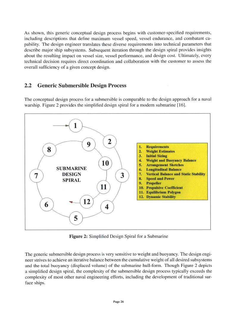
The conceptual design process for a submersible is comparable to the design approach for a navalwarship. Figure 2 provides the simplified design spiral for a modem submarine [16].
Figure 2: Simplified Design Spiral for a Submarine
The generic submersible design process is very sensitive to weight and buoyancy. The design engi-neer strives to achieve an iterative balance between the cumulative weight of all desired subsystemsand the total buoyancy (displaced volume) of the submarine hull-form. Though Figure 2 depictsa simplified design spiral, the complexity of the submersible design process typically exceeds thecomplexity of most other naval engineering efforts, including the development of traditional sur-face ships.
Page 26
1. Requirements2. Weight Estimates3. Initial Sizing4. Weight and Buoyancy Balance5. Arrangement Sketches6. Longitudinal Balance7. Vertical Balance and Static Stability8. Speed and Power9. Propeller10. Propulsive Coefficient11. Equilibrium Polygon12. Dynamic Stability
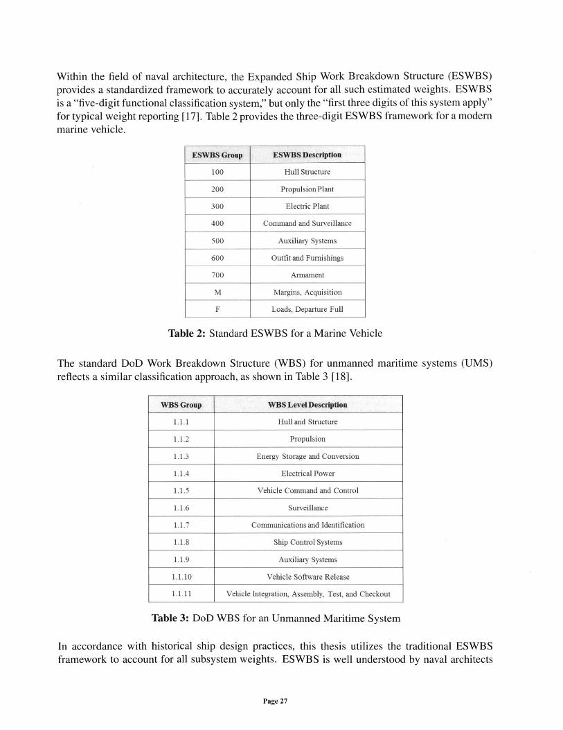
Within the field of naval architecture, the Expanded Ship Work Breakdown Structure (ESWBS)provides a standardized framework to accurately account for all such estimated weights. ESWBSis a "five-digit functional classification system," but only the "first three digits of this system apply"for typical weight reporting [17]. Table 2 provides the three-digit ESWBS framework for a modemmarine vehicle.
ESWBS Group ESWBS Description
100 Hull Structure
200 PropulsionPlant
300 Electric Plant
400 Command and Surveillance
500 Auxiliary Systems
600 Outfit and Furnishings
700 Armament
M Margins, Acquisition
F Loads, Departure Full
Table 2: Standard ESWBS for a Marine Vehicle
The standard DoD Work Breakdown Structure (WBS) for unmanned maritime systems (UMS)reflects a similar classification approach, as shown in Table 3 [18].
WBS Group WBS Level Description
1.1.1 Hull and Structure
1.1.2 Propulsion
1.1.3 Energy Storage and Conversion
1.1.4 Electrical Power
1.1.5 Vehicle Command and Control
1.1.6 Surveillance
1.1.7 Communications and Identification
1.1.8 Ship Control Systems
1.1.9 Auxiliary Systems
1.1.10 Vehicle Software Release
1.1.11 Vehicle Integration, Assembly, Test, and Checkout
Table 3: DoD WBS for an Unmanned Maritime System
In accordance with historical ship design practices, this thesis utilizes the traditional ESWBSframework to account for all subsystem weights. ESWBS is well understood by naval architects
Page 27
and marine engineers, and three-digit weight group accountability provides sufficient fidelity forthe conceptual design process.
As no standardized design spiral exists for UUV development, this thesis integrates many aspectsof the traditional (large-scale) submarine design process. As applicable, the author attemptedto account for all major ESWBS components within the proposed conceptual design program.Ultimately, this thesis reflects a feasible approach to explore a broad design space.
2.3 Program Structure and Functionality
The widespread availability of high-powered computers and advanced engineering software hasrevolutionized modern naval architecture. Hand-drawn ship designs have been replaced by de-tailed, three-dimensional computer models. Advanced computer algorithms, such as robust op-timization routines, have allowed the practicing naval architect to rapidly explore hundreds offeasible designs in a single workday. Within the Navy, efforts to expedite and improve the shipdesign process are best reflected by proprietary software programs, such as the Advanced Ship andSubmarine Evaluation Tool (ASSET).
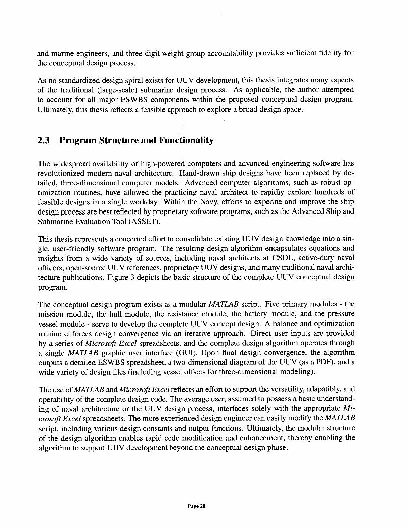
This thesis represents a concerted effort to consolidate existing UUV design knowledge into a sin-gle, user-friendly software program. The resulting design algorithm encapsulates equations andinsights from a wide variety of sources, including naval architects at CSDL, active-duty navalofficers, open-source UUV references, proprietary UUV designs, and many traditional naval archi-tecture publications. Figure 3 depicts the basic structure of the complete UUV conceptual designprogram.
The conceptual design program exists as a modular MATL4B script. Five primary modules - themission module, the hull module, the resistance module, the battery module, and the pressurevessel module - serve to develop the complete UUV concept design. A balance and optimizationroutine enforces design convergence via an iterative approach. Direct user inputs are providedby a series of Microsoft Excel spreadsheets, and the complete design algorithm operates througha single MATLAB graphic user interface (GUI). Upon final design convergence, the algorithmoutputs a detailed ESWBS spreadsheet, a two-dimensional diagram of the UUV (as a PDF), and awide variety of design files (including vessel offsets for three-dimensional modeling).
The use of MATLAB and Microsoft Excel reflects an effort to support the versatility, adapatibly, andoperability of the complete design code. The average user, assumed to possess a basic understand-ing of naval architecture or the UUV design process, interfaces solely with the appropriate Mi-crosoft Excel spreadsheets. The more experienced design engineer can easily modify the MATLABscript, including various design constants and output functions. Ultimately, the modular structureof the design algorithm enables rapid code modification and enhancement, thereby enabling thealgorithm to support UUV development beyond the conceptual design phase.
Page 28
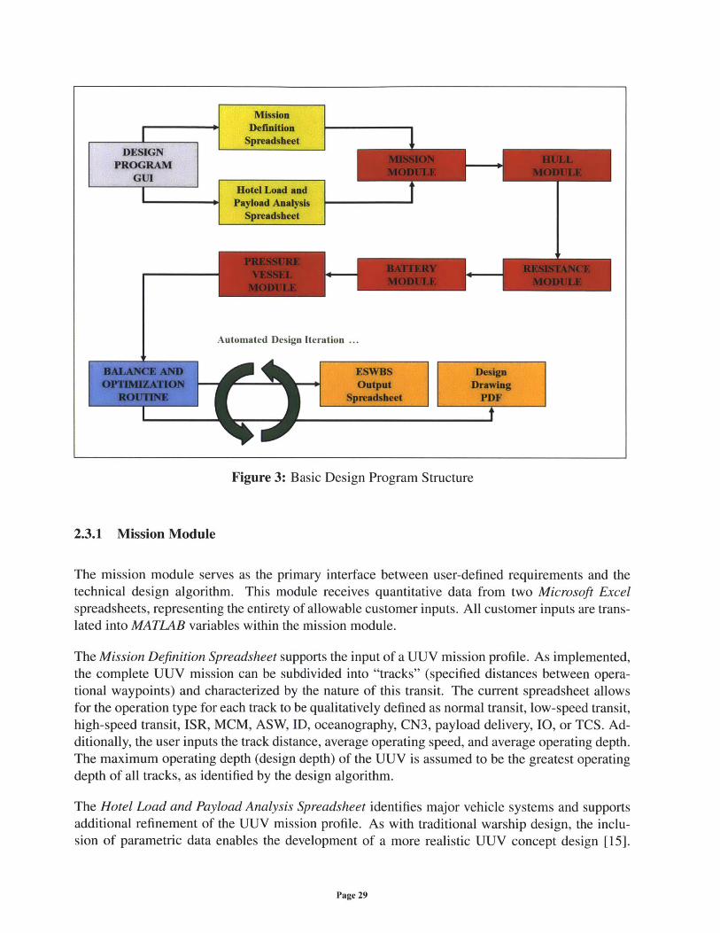
Figure 3: Basic Design Program Structure
2.3.1 Mission Module
The mission module serves as the primary interface between user-defined requirements and thetechnical design algorithm. This module receives quantitative data from two Microsoft Excelspreadsheets, representing the entirety of allowable customer inputs. All customer inputs are trans-lated into MATLAB variables within the mission module.
The Mission Definition Spreadsheet supports the input of a UUV mission profile. As implemented,the complete UUV mission can be subdivided into "tracks" (specified distances between opera-tional waypoints) and characterized by the nature of this transit. The current spreadsheet allowsfor the operation type for each track to be qualitatively defined as normal transit, low-speed transit,high-speed transit, ISR, MCM, ASW, ID, oceanography, CN3, payload delivery, IO, or TCS. Ad-ditionally, the user inputs the track distance, average operating speed, and average operating depth.The maximum operating depth (design depth) of the UUV is assumed to be the greatest operatingdepth of all tracks, as identified by the design algorithm.
The Hotel Load and Payload Analysis Spreadsheet identifies major vehicle systems and supportsadditional refinement of the UUV mission profile. As with traditional warship design, the inclu-sion of parametric data enables the development of a more realistic UUV concept design [15].
Page 29
I
Within this spreadsheet, the author considered parametric data from a wide variety of sources, in-cluding previous UUV designs, discussions with CSDL naval architects, and technical data-sheetsfrom component manufacturers. For this phase of the design program, parametric data allowedthe author to identify a minimum complement of shipboard systems required for a UUV design.This spreadsheet considers nine major UUV components: a vehicle controller; an autonomy con-troller; a payload controller; a variable ballast system; a combined inertial navigation system (INS),Doppler velocity log (DVL), and global positioning system (GPS); a pressure sensor; a forward-looking sonar (FLS); a side-looking sonar (SLS); and a synthetic aperture sonar (SAS). Figure 4provides a two-dimensional depiction of some major UUV systems and components for this thesis.
PressureVessel
ControlSurface
vehileconiilerAutaonmy Cozaer IN DVLGs
ElectricMotor Battery System Payload C/DL/olleP
Ballast Modular Mission Payload F'SS'S System SAS
Hull StienerEnvelope (Frame)
Figure 4: Major UUV Systems and Components
The Hotel Load and Payload Analysis Spreadsheet contains a library of parametric data for com-mon UUV components, including values for average unit power, average unit weight, and averageunit volume. The user specifies the redundancy factor for each major component, a setting thatsimply alters the total shipboard quantity of each component. For example, if the customer desiresredundancy for the shipboard pressure sensor, the UUV concept design will include two pressuresensors. The spreadsheet also allows the user to turn a specific system on or off for a given opera-tion type. For example, for a high-speed transit, the SAS may be turned off, as the sonar may onlybe designed for operation during low vessel speeds. This format provides tremendous flexibilityto define the anticipated hotel load of the vehicle, a value that represents the non-propulsive powerconsumption of the total UUV system.
Supporting the development of payload-centric UUVs, the Hotel Load and Payload AnalysisSpreadsheet allows for the definition of a modular mission payload. The user provides quantitativevalues for payload weight, payload volume, and estimated payload hotel load. Additionally, thecustomer can turn the payload on or off for a specific (qualitative) UUV operation type. The usercan also specify appropriate vehicle design margins within this spreadsheet, allowing for greaterdesign conservatism.
Ultimately, the mission module consolidates all quantitative values from these two Microsoft Excelspreadsheets into variables used by subsequent modules of the MATLAB script. Many of thesevariables serve as the requirements for the design spiral, thereby describing and constraining thetechnical feasibility of the final concept design.
Page 30
2.3.2 Hull Module
The hull module defines the geometry of the hull envelope, creates a table of offsets, and calcu-lates the principal characteristics of the resulting UUV hull-form. Definition of the hull envelopeconstrains the arrangeable volume of the UUV and enables a subsequent estimation of total shipresistance.
A review of existing hull geometries revealed tremendous design variability within the currentUUV market. Many modem UUVs feature "torpedo-shaped" envelopes. However, there are manyUUVs with hydrodynamically inefficient hull-forms, such as the rectangular structures of modernROVs [19]. Given the current strategic focus on developing high-endurance UUVs, the authorexcluded these inefficient hull-forms as candidate geometries for the design algorithm.
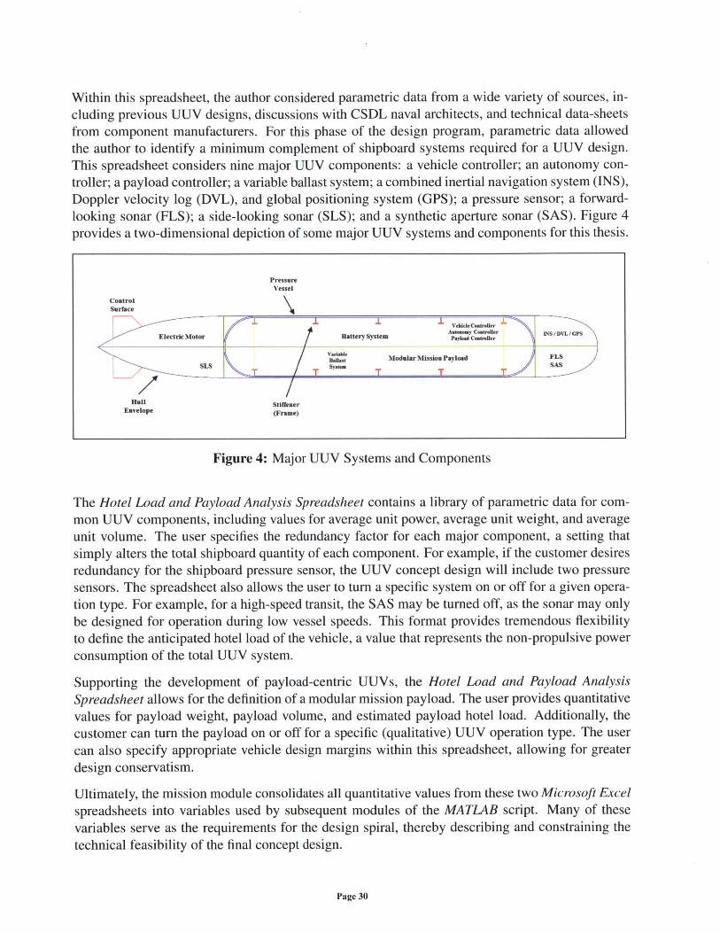
To limit the extent of the conceptual design space, this thesis assumes a standard submarine hullgeometry as the UUV hull envelope. This envelope geometry, referred to as a "Jackson" hull-form,features an axisymmetric body-of-revolution with an ellipsoidal fore-body, a parallel mid-body(PMB), and a paraboloid aft-body [20]. Figure 5 displays the corresponding parameters for thishull-form. Validation of this geometry will be discussed in Section 3.1 and Section 3.2 of thisthesis, and alternative hull geometry options are presented in Appendix A.
Figure 5: Standard Jackson Hull-Form Geometry
As shown, the Jackson hull-form is defined by the length of the fore-body (LF), the length of thePMB (Lm), and the length of the aft-body (LA). For this thesis, the hull length (L) is the primaryindependent variable for design iteration. The diameter of the hull envelope (D) is a function ofthe hull length and a constant length-to-diameter ratio (j) value:
LD (L)
Page 31
D
Accordingly, for a fixed hull length, the length of the fore-body is a function of the hull diameterand a forward hull-section length factor (CFWD):
LLF CFWDx D= CFWD X
Similarly, the length of the aft-body is a function of the hull diameter and an aft hull-section lengthfactor (CAFT):
LLA = CAFT x D = CAFT X
Therefore, the length of the PMB is calculated by the following equation:
LM -L F + LA) = L - [(CFWD x D)+ (CAFT xD)] =L 1- CFWD-- CAFT
As shown, for a feasible hull design, the sum of the forward hull-section length factor and the afthull-section length factor must be less than or equal to the length-to-diameter ratio. If this sum isequal to the length-to-diameter ratio, the hull geometry will possess no PMB.
For the ellipsoidal fore-body, the radial offset (yF) from the centerline is a function of the hulldiameter, the length of the fore-body, a local distance (xF) measured from the aft-most componentof the fore-body, and the forward hull-section curvature factor (nF):
1
YF=D [I xF )nF nF
2 LF
For the paraboloid aft-body, the radial offset (yA) from the centerline is a function of the hull diam-eter, the length of the aft-body, a local distance (xA) measured from the forward-most componentof the aft-body, and the aft hull-section curvature factor (nA):
ya = - - A2 LA _
For the PMB, the radial offset from the centerline is equivalent to the hull radius, as the PMB isa cylindrical body-of-revolution. All offset values are consolidated into a single table of offsets,thereby allowing data exportation to three-dimensional modeling software. Within this table, radialoffset values are presented as a function of an absolute (global) length measured from the bow ofthe hull-form.
The development of a table of offsets enables the calculation of various principal characteristics.In accordance with standard naval architecture practices, the design algorithm calculates the fol-lowing principal characteristics of the UUV hull envelope:
Page 32
* Sectional Area
" Envelope Volume (VE)
" Wetted Surface-Area (S)
" Prismatic Coefficient (Ce)
Given the advanced computational capability of MATLAB, the current design algorithm calculatesthese parameters via direct subdivision of the complete hull-form into many thin, cross-sectional"slices," as derived from the radial offset value and a fixed width (station spacing) value. Alterna-tively, to improve the computational efficiency of the algorithm, all parameters could be tabulatedvia direct integration of the radial offset equations, though such equations may be undefined fornon-Jackson geometries. However, the author determined that such efforts were extraneous, as theencoded method provides sufficient fidelity to accurately calculate all principal characteristics.
2.3.3 Resistance Module
The resistance module calculates the total resistance of the UUV system. Additionally, the resis-tance module includes elements of basic control surface design and propeller selection. Outputsfrom the resistance module provide an estimation of total propulsive power for the UUV, enablingthe subsequent design of a battery system.
Total ship resistance (RT) is composed of several significant resistance components [21, 22]. Perstandard practice, these components are expressed as non-dimensional coefficients. The coefficientof total resistance (CT) is a function of the total ship resistance, the mass-density of water (p), thewetted surface-area (S) of the submerged hull-form, and the speed of the ship (V):
RTCT = {pSV 2
For a typical ship operating near the free-surface, the coefficient of total resistance can be decom-
posed into the coefficient of wave-making resistance (Cw) and the coefficient of viscous resistance
(Cv). At a given speed, the coefficient of wave-making resistance is a function of the Froude num-
ber (F,), and the coefficient of viscous resistance is a function of the Reynolds number (R). The
Froude number is expressed as a function of the ship speed (V), the acceleration of gravity (g), andthe hull length (L):
VFn =
Similarly, the Reynolds number is expressed as a function of the ship speed, the maximum hulllength, and the kinematic viscosity of water (v):
Page 33
VLRn =
V
Accordingly, the coefficient of total resistance, a function of both the Froude number and theReynolds number, can be approximated as the sum of the coefficient of wave-making resistanceand the coefficient of viscous resistance:
CTr~ Cw (Fn)+Cv (Rn)
Wave-making resistance results from the work "done by the ship hull on the surrounding fluid to
generate waves," and gravitational effects govern this wave formation [23]. However, "the modem
submarine experiences no wave-making resistance whatsoever when submerged more than three
diameters from the free-surface" [21]. Thus, for a "deeply-submerged" submarine (operating at
a depth greater than three hull diameters), the coefficient of total resistance is solely a function
of the coefficient of viscous resistance [10]. As such, the design algorithm developed for this
thesis ignores all (near-surface) wave-making effects. For the bare-hull condition, the coefficient
of viscous resistance can be decomposed into the coefficient of frictional resistance (CF) and the
coefficient of residual resistance (CR):
CT =CV= CF+CR
To account for material roughness effects, a roughness (or correlation) allowance (CA) is included
in the equation for the coefficient of total resistance (for the bare-hull condition):
CT =CV+CA =CF+CR±CA
To calculate the coefficient of frictional resistance, this thesis applies the standard equation devel-
oped by the International Towing Tank Conference (ITTC) in 1957, accounting for some three-
dimensional ship effects [22]:
0.075CF=
[loglo (Rn) - 2]2
Ideally, model test data would be used to derive the full-scale coefficient of total resistance. How-
ever, for the iterative conceptual design process, empirical resistance equations provide sufficient
accuracy to approximate the coefficient value. For this thesis, the author considered twelve empir-
ical approaches:
Page 34
1. Gillmer and Johnson Method [21]
2. Bottaccini Method [24]
3. Yefim'yev Calculated Eddy Resistance Method [25, 26]
4. Yefim'yev Interpolated Eddy Resistance Method [25, 26]
5. Chhabra Method [27]
6. Allmendinger and Hoerner Frontal-Area Method [10, 28]
7. Allmendinger and Hoerner Wetted Surface-Area Method [10, 28]
8. Allmendinger and Hoerner Volume Method [10, 28]
9. Jackson Curve-Fit Method [16, 20]
10. Jackson and Hoerner Method [16, 20]
11. Jackson Parallel Mid-Body Method [16, 20]
12. Martz Method [29]
These empirical methods reflect historical efforts to estimate the total resistance of full-scale sub-
marines and torpedo-shaped bodies. The author assumed that these equations could be used, within
reason, to predict the bare-hull resistance of UUVs. Validation of this assumption will be presented
in Section 3.2 of this thesis. The following unique methods represent twelve potential options to
calculate the coefficient of total resistance for a deeply-submerged hull-form:
1. For the Gillmer and Johnson Method, the coefficient of total resistance is a function of
the coefficient of frictional resistance (per ITTC), the hull geometry, and the roughness al-
lowance:D /D\' +
CT=CV+CA= CF 1+ L+3( j A
2. For the Bottaccini Method, the UUV hull-form is assumed to be "submerged in a viscous
incompressible fluid of infinite extent" and operating at a "small angle-of-attack" [24]. For
an axisymmetric UUV hull-form, the maximum cross-sectional area (A) is a function of the
maximum hull diameter:
A = -D2 4 4
Thus, for the Bottaccini Method, the following equation predicts the coefficient of total
resistance:
CT SCF L 4 L)A(L4 D 2D
Page 35
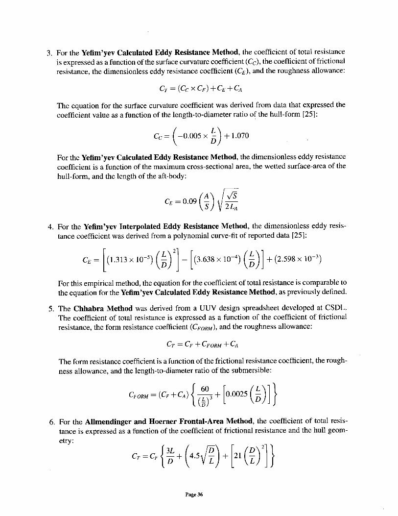
3. For the Yefim'yev Calculated Eddy Resistance Method, the coefficient of total resistanceis expressed as a function of the surface curvature coefficient (Cc), the coefficient of frictionalresistance, the dimensionless eddy resistance coefficient (CE), and the roughness allowance:
CT = (Cc X CF) +CE +CA
The equation for the surface curvature coefficient was derived from data that expressed thecoefficient value as a function of the length-to-diameter ratio of the hull-form [25]:
Cc = (0.005 x -)+ 1.070D
For the Yefim'yev Calculated Eddy Resistance Method, the dimensionless eddy resistancecoefficient is a function of the maximum cross-sectional area, the wetted surface-area of thehull-form, and the length of the aft-body:
CE -0-09(A) 2 LA
4. For the Yefim'yev Interpolated Eddy Resistance Method, the dimensionless eddy resis-tance coefficient was derived from a polynomial curve-fit of reported data [25]:
CE = (1.313 x 10 5) (iL)j (3.638 x 10⁴) (L)l + (2.598 x 10⁻³)
For this empirical method, the equation for the coefficient of total resistance is comparable tothe equation for the Yefim'yev Calculated Eddy Resistance Method, as previously defined.
5. The Chhabra Method was derived from a UUV design spreadsheet developed at CSDL.The coefficient of total resistance is expressed as a function of the coefficient of frictionalresistance, the form resistance coefficient (CFORM), and the roughness allowance:
CT = CF +CFORM +CA
The form resistance coefficient is a function of the frictional resistance coefficient, the rough-ness allowance, and the length-to-diameter ratio of the submersible:
CFORM (CF + CA) 3 + 0.0025 (-)}t (L) 3D_
6. For the Allmendinger and Hoerner Frontal-Area Method, the coefficient of total resis-tance is expressed as a function of the coefficient of frictional resistance and the hull geom-etry:
CT = CF{L + 4.5 + 21(D)2
Page 36
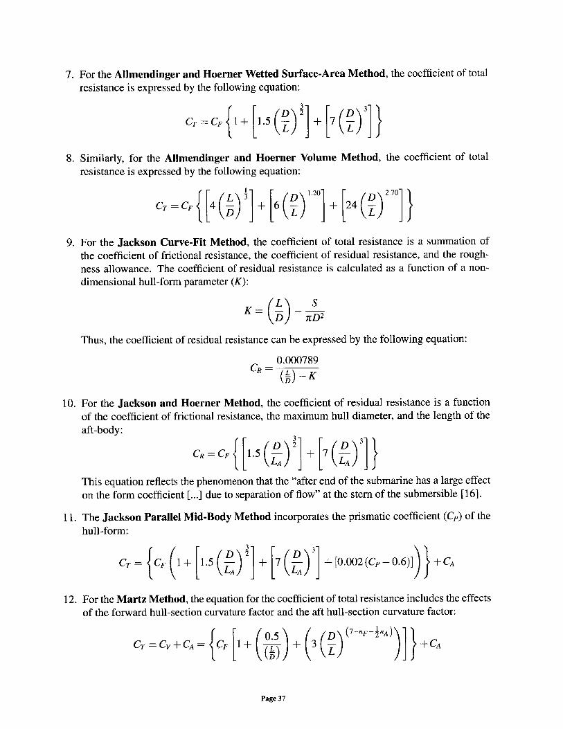
7. For the Allmendinger and Hoerner Wetted Surface-Area Method, the coefficient of totalresistance is expressed by the following equation:
CT =CF I+ 1.5 () + 7 -L L
8. Similarly, for the Allmendinger and Hoerner Volume Method, the coefficient of totalresistance is expressed by the following equation:
CT =CF 4 (L) j [ (2) + 24 (D)
9. For the Jackson Curve-Fit Method, the coefficient of total resistance is a summation ofthe coefficient of frictional resistance, the coefficient of residual resistance, and the rough-ness allowance. The coefficient of residual resistance is calculated as a function of a non-dimensional hull-form parameter (K):
K = -L
Thus, the coefficient of residual resistance can be expressed by the following equation:
0.000789CR-~
CR=(L) -K
10. For the Jackson and Hoerner Method, the coefficient of residual resistance is a functionof the coefficient of frictional resistance, the maximum hull diameter, and the length of theaft-body:
CR =CF 1.5 ( + 7( )]
( L )3 -AThis equation reflects the phenomenon that the "after end of the submarine has a large effecton the form coefficient [...] due to separation of flow" at the stern of the submersible [16].
11. The Jackson Parallel Mid-Body Method incorporates the prismatic coefficient (Cp) of thehull-form:
CT = CF 1+ 1.5 ] + [7 ( + [0.002(Cp-0.6)] +CA
12. For the Martz Method, the equation for the coefficient of total resistance includes the effectsof the forward hull-section curvature factor and the aft hull-section curvature factor:
CT =CV+CA= CF [+ (.) + 3 (] + A- (Tio) L
Page 37
As validated in Section 3.2, the design algorithm uses an average of the Gillmer and JohnsonMethod (CT1), the Chhabra Method (CT5), the Allmendinger and Hoerner Wetted Surface-Area Method (CT7), the Jackson Curve-Fit Method (CT9), and the Martz Method (CT12 ) topredict the total bare-hull resistance (RTHULL) of the UUV:
RTHULL pSV2 (CT + CT 5 + CT7 ± CT 9 + CT12 )
To account for the added resistance of all control surfaces and appendages, the design algorithmexpresses the appendage resistance coefficient (CApp) as a function of the wetted surface-area of allappendages (SApp) and the hull geometry [20]:
LDCAP
1000 SAPP
Therefore, for the conceptual design phase, the total appendage resistance (RApp) is estimated bythe following equation:
1 ____pV 2 LDRApP - P(SApp) (V2) (CAPP) _
2 2000
For this thesis, control surfaces are the only appendages included in the concept design. The designalgorithm outputs a basic control surface configuration for the UUV, featuring four stern controlsurfaces. Two vertical control surfaces provide "course-keeping stability," and two horizontal con-trol surfaces provide pitch control and dynamic stability [30]. The author did not include forwardcontrol surfaces in the concept design, and the outer extents of all stern appendages are confinedto the maximum diameter of the UUV hull-form.
To approximate the size of all control surfaces, the author considered parametric data from full-scale submarine designs [16]. The lateral area of each control surface (ALTSURF) is a function ofthe lateral area of the entire submersible (AMTHULL), and all four control surfaces are equivalentin size [31]. Assuming that the UUV can be classified as a "warship," the total required controlsurface lateral area (AuTREQ) can be estimated by the following equation:
ALATREQ = 0.028 x ALATHULL = 8 x ALATSURF
This equation allows the design algorithm to create realistic control surfaces for the UUV conceptdesign. For the conceptual design phase, the fidelity of each control surface is limited to a simpletwo-dimensional representation of each appendage.
The effective horsepower (EHP) of the vessel is calculated by the following equation (in UnitedStates customary units):
Page 38
EHP= -_(RTHULL + RApp) V550
For a given operating speed, the shaft horsepower (SHP) value represents the primary compo-nent of the expected propulsive load. For this thesis, the author assumed a standard propulsivecoefficient (PC) value, but Appendix A provides an approach to estimate this value via propeller
design and selection. Accordingly, the shaft horsepower is expressed as a function of the effectivehorsepower and the propulsive coefficient:
EHPSHP = PC
Ultimately, this empirical approach represents a significant element of the "design spiral" for theconceptual design process. Outputs from the resistance module support the battery selection pro-cess and provide a greater understanding of the operational capabilities of the vessel.
2.3.4 Battery Module
The battery module utilizes values from the mission module and the resistance module to estimatethe weight and volume of the shipboard battery system. The total vehicle energy (ET) is a functionof the propulsive load (Ep) and the vehicle hotel load (EH):
ET = EP+EH
The propulsive load and hotel load are calculated for each specific track interval. For a single track,
the operating time (T) is a function of the track distance (Di) and the user-defined operating speed(V) for the track (per the mission module):
Ti =Vi
Consequently, this time interval is used to calculate the incremental vehicle energy (Erg) for a
single track, where the incremental propulsive load (Ep,) and the incremental hotel load (EHg) arise
from the conversion of vehicle power to vehicle energy. For each track, if the shaft horsepowerrepresents propulsive power (for a specific vessel speed), and the incremental hotel power (PHi)
values are calculated by the mission module, the following equation results:
Er= Ep, +EHi (SHP x T)+(PH, x T1)
Page 39
Thus, the total vehicle energy is a summation of all incremental energy values for the total numberof user-defined tracks (nT):
nT nT
ET=(ET) =( (Ep,+EHii=1 i=1
As shown, the propulsive load is a function of the vehicle speed and the operating time. Theestimated hotel load is a function of the user-defined mission systems (turned on or off) and theoperating time. Accordingly, the battery weight (WBATT) is a function of the total vehicle energyand the specific energy (SEBATT) of the selected battery technology:
WBATT ESEBATT
The battery volume (VBATT) is a function of the total vehicle energy and the energy density (EDBATT)
of the battery technology:
E TVBAT T T
EDBATT
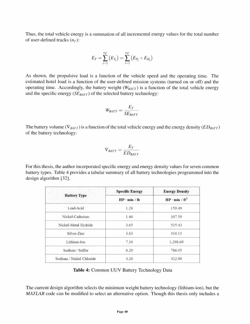
For this thesis, the author incorporated specific energy and energy density values for seven commonbattery types. Table 4 provides a tabular summary of all battery technologies programmed into thedesign algorithm [32].
Table 4: Common UUV Battery Technology Data
The current design algorithm selects the minimum weight battery technology (lithium-ion), but theMATLAB code can be modified to select an alternative option. Though this thesis only includes a
Page 40
Specific Energy Energy DensityBattery Type
HP -min / lb HP -min / W
Lead-Acid 1.28 159.49
Nickel-Cadmium 1.46 307.59
Nickel-Metal Hydride 3.65 535.43
Silver-Zinc 3.83 410.11
Lithium-Ion 7.30 1,298.69
Sodium / Sulfur 6.20 786.05
Sodium / Nickel Chloride 4.20 432.90
broad analysis of UUV battery technology, the complexity and significance of this element of thedesign spiral should not be overlooked by the design engineer. Existing battery technology trulylimits the versatility of modern UUVs. Rapid advances in UUV battery technology, such as thedesign of capable fuel-cell systems, will support the high-endurance UUVs of the future. However,given concerns about developmental maturity and technical complexity, the author did not includesuch fuel-cell systems in the current conceptual design tool.
2.3.5 Pressure Vessel Module
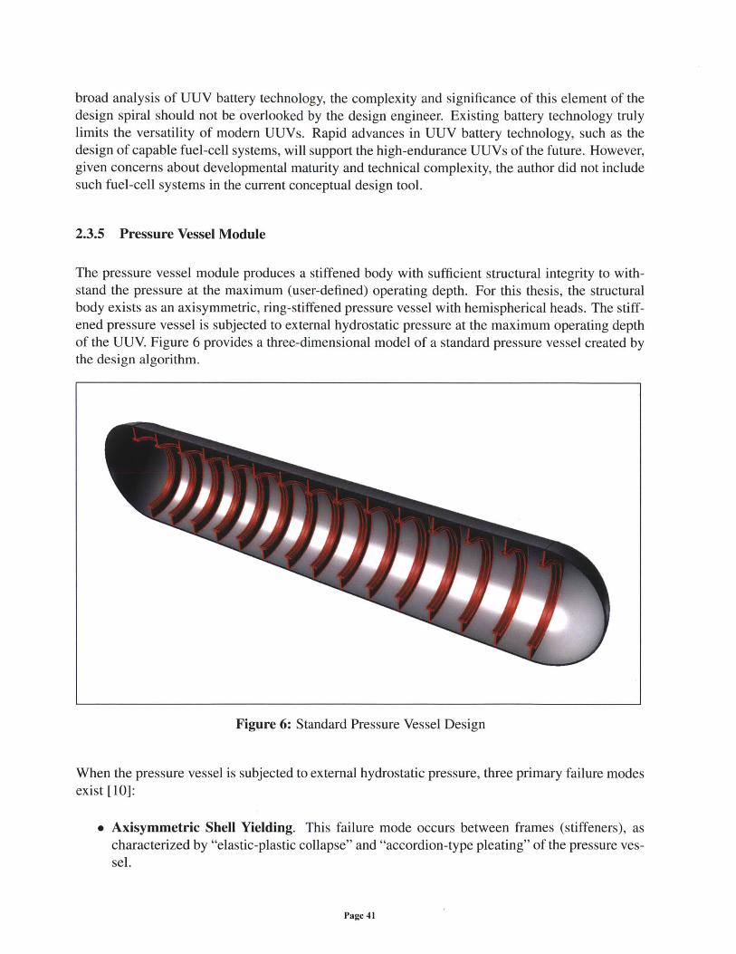
The pressure vessel module produces a stiffened body with sufficient structural integrity to with-stand the pressure at the maximum (user-defined) operating depth. For this thesis, the structuralbody exists as an axisymmetric, ring-stiffened pressure vessel with hemispherical heads. The stiff-ened pressure vessel is subjected to external hydrostatic pressure at the maximum operating depthof the UUV. Figure 6 provides a three-dimensional model of a standard pressure vessel created bythe design algorithm.
Figure 6: Standard Pressure Vessel Design
When the pressure vessel is subjected to external hydrostatic pressure, three primary failure modesexist [10]:
* Axisymmetric Shell Yielding. This failure mode occurs between frames (stiffeners), ascharacterized by "elastic-plastic collapse" and "accordion-type pleating" of the pressure ves-sel.
Page 41
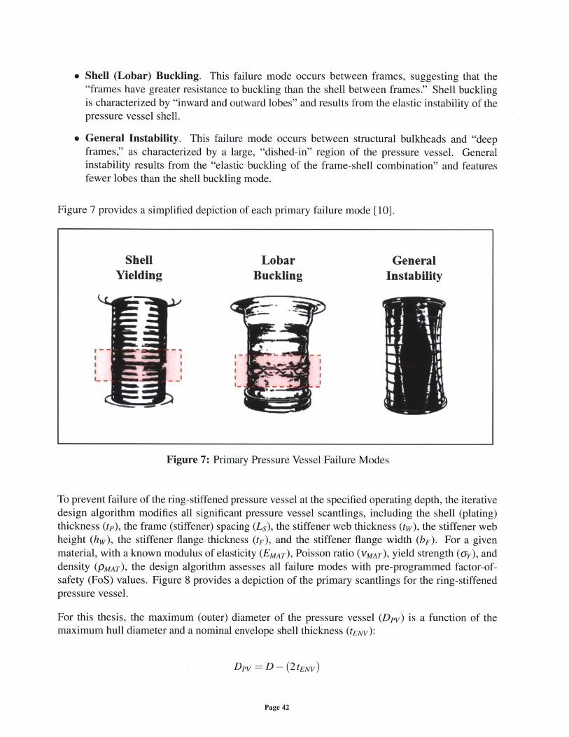
" Shell (Lobar) Buckling. This failure mode occurs between frames, suggesting that the"frames have greater resistance to buckling than the shell between frames." Shell bucklingis characterized by "inward and outward lobes" and results from the elastic instability of thepressure vessel shell.
" General Instability. This failure mode occurs between structural bulkheads and "deepframes," as characterized by a large, "dished-in" region of the pressure vessel. Generalinstability results from the "elastic buckling of the frame-shell combination" and featuresfewer lobes than the shell buckling mode.
Figure 7 provides a simplified depiction of each primary failure mode [10].
Shell Lobar GeneralYielding Buckling Instability
Figure 7: Primary Pressure Vessel Failure Modes
To prevent failure of the ring-stiffened pressure vessel at the specified operating depth, the iterativedesign algorithm modifies all significant pressure vessel scantlings, including the shell (plating)thickness (tp), the frame (stiffener) spacing (Ls), the stiffener web thickness (tw), the stiffener webheight (hw), the stiffener flange thickness (tF), and the stiffener flange width (bF). For a givenmaterial, with a known modulus of elasticity (EMAT), Poisson ratio (VMAT), yield strength (-y), anddensity (PMAT), the design algorithm assesses all failure modes with pre-programmed factor-of-safety (FoS) values. Figure 8 provides a depiction of the primary scantlings for the ring-stiffenedpressure vessel.
For this thesis, the maximum (outer) diameter of the pressure vessel (Dpv) is a function of themaximum hull diameter and a nominal envelope shell thickness (tENV:
Dpv =D - (2tENV)
Page 42
MWI-I I
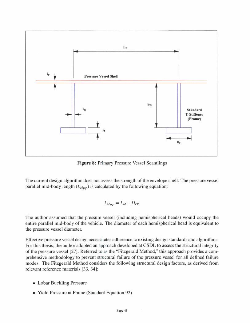
tpPressure Vessel Shell
hwtw Standard
T-Stiffener(Frame)
tF
bF
Figure 8: Primary Pressure Vessel Scantlings
The current design algorithm does not assess the strength of the envelope shell. The pressure vesselparallel mid-body length (LMPv) is calculated by the following equation:
LMPV - Lm - Dpv
The author assumed that the pressure vessel (including hemispherical heads) would occupy theentire parallel mid-body of the vehicle. The diameter of each hemispherical head is equivalent tothe pressure vessel diameter.
Effective pressure vessel design necessitates adherence to existing design standards and algorithms.For this thesis, the author adopted an approach developed at CSDL to assess the structural integrityof the pressure vessel [27]. Referred to as the "Fitzgerald Method," this approach provides a com-prehensive methodology to prevent structural failure of the pressure vessel for all defined failuremodes. The Fitzgerald Method considers the following structural design factors, as derived fromrelevant reference materials [33, 34]:
" Lobar Buckling Pressure
" Yield Pressure at Frame (Standard Equation 92)
Page 43
* Yield Pressure at Mid-Bay (Standard Equation 92A)
" Yield Pressure at Mid-Bay (Modified Equation 92A)
" General Instability (Bryant Equation)
" General Instability (Modified Bryant Equation)
" Frame Instability Buckling Pressure (Modified Tokugawa Equation for an Infinite Cylinder)
" Frame Hoop Stress (Compressive Stress)
" Frame Hoop Stress (Bending Stress)
" Total Frame Stress
The author also considered an approach developed by the American Bureau of Shipping (ABS),referred to as the "ABS Method" [35]. Though the ABS Method is intended for the design ofmanned submersibles, the author assumed that the inherent conservatism of such an approachwould benefit the conceptual design process. A more robust pressure vessel design may mitigateUSN concerns about "implodable volumes," and design standardization with existing classificationsocieties complies with current NAVSEA practice for modern surface combatant designs [36]. TheABS Method considers the following structural design factors:
" Inter-Stiffener Strength
" Longitudinal Frame Strength (Yield)
" Buckling Strength
" Stiffener Strength
* Stiffener Tripping
" Local Stiffener Flange Buckling
* Local Stiffener Web Buckling
" Combined (Stiffener and Shell) Moment-of-Inertia
Per recommendations from naval architects at CSDL, the design algorithm produces a pressurevessel that passes all traditional design criteria (as defined by the Fitzgerald Method). For academicpurposes, the algorithm also assesses the satisfaction of ABS structural design criteria. Stiffenerstrength, tripping, buckling, and moment-of-inertia factors are considered for both "non-heavy"stiffeners and "heavy" frames (''king frames"). The ABS document provides relevant FoS valuesfor the given pressure vessel design, but these values differ from those considered for the FitzgeraldMethod [35]. Validation and comparison of both structural design approaches will be presented inSection 3.3 of this thesis.
Page 44
Though the Fitzgerald Method and the ABS Method provide mechanisms to assess a design with
known scantlings and material properties, the selection of initial scantlings remains unaddressed.To limit the extent of the design space, the author integrated a unique structural optimizationmethodology (referred to as the "Gorman Method") into the design algorithm. This method "ex-
plicitly considers hull yielding, lobar (inter-frame) buckling, general instability, and local frameinstability failure modes" [37]. Within the MATLAB script, the Gorman Method determines theshell thickness, frame spacing, stiffener web thickness, stiffener web height, stiffener flange thick-ness, and stiffener flange width for the pressure vessel design.
The Gorman Method includes three design factors (comparable to FoS values): a design factorfor shell membrane yield (SFy), a design factor for lobar buckling (SFL), and a design factor for
general instability (SFB). The methodology begins with the calculation of the external pressure(Pop) for the maximum operating depth of the vessel (hop). If the operating depth is measured infeet, and the pressure is measured in pounds per square-inch, the following equation is valid (fortypical environmental conditions):
PP - 0.445 hop
Consequently, the minimum shell thickness (tpMIN) can be calculated by the following equation,where the shell thickness is measured in inches, the pressure vessel diameter is measured in inches,and the yield strength is measured in pounds per square-inch:
Pop x Dpv x SFYtPMIN= 2a
An acceptable stiffener spacing (measured in inches) results from the following equation:
Ls = X tPMIN 2.60 EMAT MI+ (0.20 hop) + SFLPop x SFL Dt ( Dp )I
To predict the moment-of-inertia for the combined (stiffener and shell) section (Is), the GormanMethod considers a rearranged version of the standard "Bryant Equation" (expressed in UnitedStates customary units):
PCR x SFB x (Dry )3 (Dpy )2 x Ls x tpMINis ={ 8 (nBcf2 1 EMAT 4 [(nB)2_1] G(mnB)
The critical inter-stiffener pressure (PcR) is provided by the following equation:
Page 45
PCR 2 .6 0EMAT
(LS) - (0.45 MNDpy ' Py
The non-dimensional buckling factor (m) is a function of the pressure vessel diameter and thepressure vessel length between bulkheads (Lc):
71Dp,m= 2Lc
For a pressure vessel design with hemispherical heads and no king frames (heavy stiffeners), thepressure vessel length between bulkheads is equal to the pressure vessel parallel mid-body length.For a fixed number of circumferential buckling waves (nB), the Bryant buckling factor (G) is de-rived from the following equation:
m 4G (mn) - 2n[(nB)2 - 1 2 [nB 2 +M2 2
Using values from all previous derivations, the Gorman Method calculates a series of non-dimensional
parameters. For two of these factors, the flange width-to-thickness ratio (c1) and the web height-to-thickness ratio (c2), the author replaced suggested (tabular) values with ABS stiffener bucklingcriteria:
Ci= 0.30 EMA T
GY
c2=0-90 EMAT
The resulting non-dimensional terms are a function of these criteria values:
(C2)+ (4Ci c2)+ (2ci)
c3 (2c2)+(4c1)
C4= C2 +(2c1)
Page 46
(2)21
C5 = { [(c2)3+(2ci )] + { C2 C3 }+ 2ci c2 + -- c 3 2
Algebraic manipulation produces a "sixth-order equation whose roots represent the optimum framethickness value" [37]:
t6+ ( 4) + + ± (12) + C =0
All terms are defined by the following equations:
Q = 12c 4 c 5
R = 12 Ls x tpMIN [(C3 )2 x c 4 +C5
S12Ls (tpMIN) 2 X C3 C4
=4Ls (tpMIN) 3 X c4] - [12C4 X II]
7 = [(Ls) (tPMIN)4] - [l2Ls X tpMN Is]
The sixth-order equation is solved (via MATLAB), and the various solutions of the optimum thick-ness value (T) are identified. The design algorithm converts the largest solution value into a designvariable (tGORMAN), and this quantity can be used to calculate corresponding stiffener scantlings:
tw = tGORMAN
hw = C2 X tGORMAN
tF= 2tGORMAN
bF = 2c 1 X tGORMAN
Though the Gorman Method provides feasible scantling values, these dimensional quantities weredetermined to be sub-optimal for specific design conditions. The nature of this sub-optimality willbe discussed in Section 3.3 of this thesis. Accordingly, to produce improved scantling values, the
Page 47
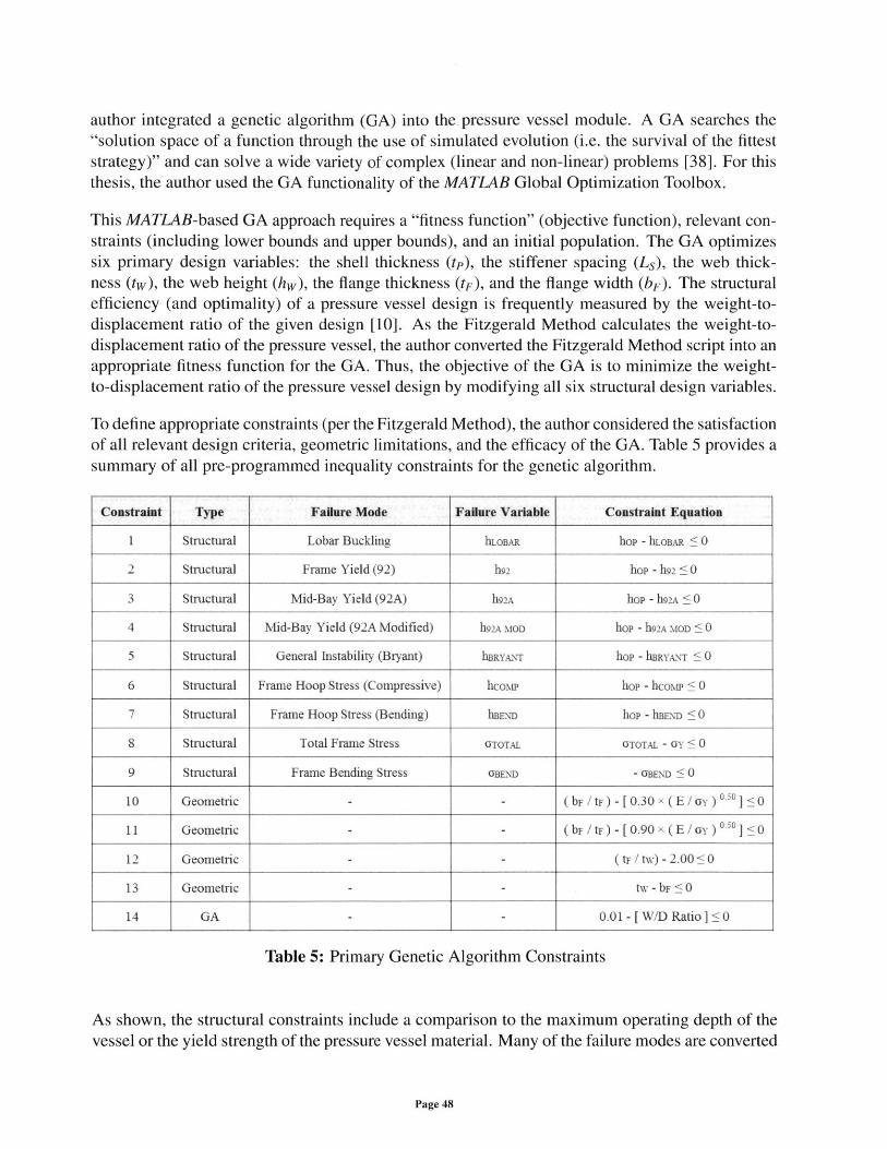
author integrated a genetic algorithm (GA) into the. pressure vessel module. A GA searches the"solution space of a function through the use of simulated evolution (i.e. the survival of the fitteststrategy)" and can solve a wide variety of complex (linear and non-linear) problems [38]. For thisthesis, the author used the GA functionality of the MATLAB Global Optimization Toolbox.
This MATLAB-based GA approach requires a "fitness function" (objective function), relevant con-straints (including lower bounds and upper bounds), and an initial population. The GA optimizessix primary design variables: the shell thickness (tp), the stiffener spacing (Ls), the web thick-ness (tw), the web height (hw), the flange thickness (tF), and the flange width (bF). The structuralefficiency (and optimality) of a pressure vessel design is frequently measured by the weight-to-displacement ratio of the given design [10]. As the Fitzgerald Method calculates the weight-to-displacement ratio of the pressure vessel, the author converted the Fitzgerald Method script into anappropriate fitness function for the GA. Thus, the objective of the GA is to minimize the weight-to-displacement ratio of the pressure vessel design by modifying all six structural design variables.
To define appropriate constraints (per the Fitzgerald Method), the author considered the satisfactionof all relevant design criteria, geometric limitations, and the efficacy of the GA. Table 5 provides asummary of all pre-programmed inequality constraints for the genetic algorithm.
Constraint Type Failure Mode Failure Variable Constraint Equation
1 Structural Lobar Buckling hLOBAR hop - hLOBAR < 0
2 Structural Frame Yield (92) h92 hop - h92 < 0
3 Structural Mid-Bay Yield (92A) h92A hop - h92A < 0
4 Structural Mid-Bay Yield (92A Modified) h92A MOD hop - h92A MOD < 0
5 Structural General Instability (Bryant) hBRYAN-r hop - hBRYANr < 0
6 Structural Frame Hoop Stress (Compressive) hcoMP hop - hcoMr _ 0
7 Structural Frame Hoop Stress (Bending) hBEND hop - hBEND < 0
8 Structural Total Frame Stress GTOTAL GTOTAL - GY < 0
9 Structural Frame Bending Stress OBEND - GBEND < 0
10 Geometric - - (bFF/t) - [0.30x (E/Gy)' 0<] <0
11 Geometric - - (bF /tF )-[ 0.90 x ( E / Gy ) 03 ] 1 0
12 Geometric - - (tF / tW) - 2.00 < 0
13 Geometric - - tw - bF < 0
14 GA - - 0.01 - [ W/D Ratio ] < 0
Table 5: Primary Genetic Algorithm Constraints
As shown, the structural constraints include a comparison to the maximum operating depth of thevessel or the yield strength of the pressure vessel material. Many of the failure modes are converted
Page 48
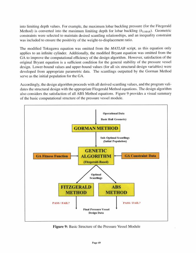
into limiting depth values. For example, the maximum lobar buckling pressure (for the FitzgeraldMethod) is converted into the maximum limiting depth for lobar buckling (hLOBAR). Geometricconstraints were selected to maintain desired scantling relationships, and an inequality constraintwas included to ensure the positivity of the weight-to-displacement ratio.
The modified Tokugawa equation was omitted from the MATLAB script, as this equation onlyapplies to an infinite cylinder. Additionally, the modified Bryant equation was omitted from theGA to improve the computational efficiency of the design algorithm. However, satisfaction of theoriginal Bryant equation is a sufficient condition for the general stability of the pressure vesseldesign. Lower-bound values and upper-bound values (for all six structural design variables) weredeveloped from appropriate parametric data. The scantlings outputted by the Gorman Methodserve as the initial population for the GA.
Accordingly, the design algorithm proceeds with all derived scantling values, and the program vali-dates the structural design with the appropriate Fitzgerald Method equations. The design algorithmalso considers the satisfaction of all ABS Method equations. Figure 9 provides a visual summaryof the basic computational structure of the pressure vessel module.
Operational Data
Basic Hul Geometry
GORMAN METHOD
Sub-Optimal Scantings
(initial Population)
GENETICAGORITHM
OptimalScantlings
FITZGERALD ABSMETHOD METHOD
PASS / FAIL? Final Pressure Vessel PS AL
Design Data
Figure 9: Basic Structure of the Pressure Vessel Module
Page 49
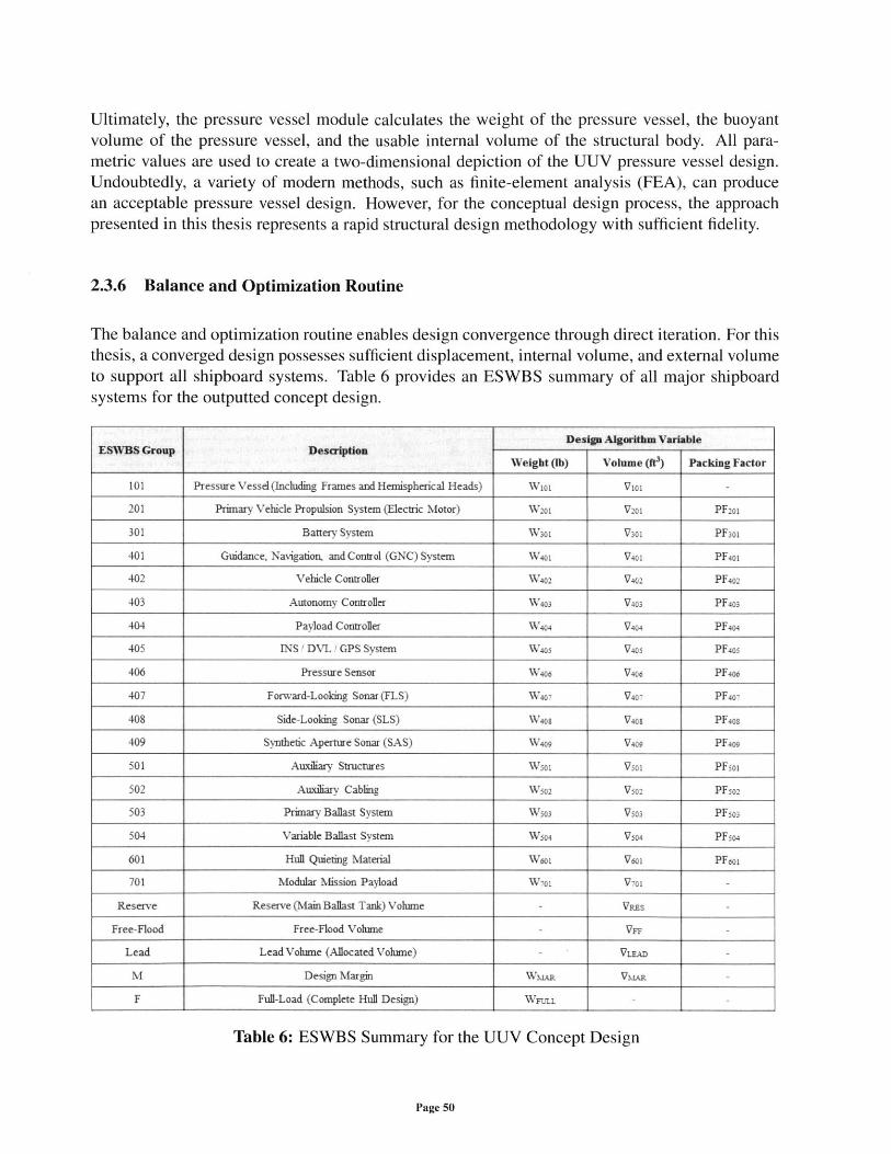
Ultimately, the pressure vessel module calculates the weight of the pressure vessel, the buoyantvolume of the pressure vessel, and the usable internal volume of the structural body. All para-metric values are used to create a two-dimensional depiction of the UUV pressure vessel design.Undoubtedly, a variety of modern methods, such as finite-element analysis (FEA), can producean acceptable pressure vessel design. However, for the conceptual design process, the approachpresented in this thesis represents a rapid structural design methodology with sufficient fidelity.
2.3.6 Balance and Optimization Routine
The balance and optimization routine enables design convergence through direct iteration. For thisthesis, a converged design possesses sufficient displacement, internal volume, and external volumeto support all shipboard systems. Table 6 provides an ESWBS summary of all major shipboardsystems for the outputted concept design.
Design Algorithm VariableESWBS Group Description_ _ _ _ _ Group_ _ Description_ W eight (b) Volum e (ft) Packing Factor
101 Pressure Vessel(Including Frames and Hemispherical Heads) Wi01 Vio1
201 Primary Vehicle Propulsion System (Electric Motor) W2 01 V201 PF2oi
301 Battery System W301 V301 PFsol
401 Guidance, Navigation, and Control (GNC) System W4oi V40i PF4oi
402 Vehicle Controller W 402 V402 PF4o2
403 Autonomy Controller W403 V403 PF403
404 Payload Controller V404 V404 PF404
405 INS./ DV.L GPS System W4os V405 PF4os
406 Pressure Sensor Wao4 V406 PF4om
407 Forward-Looking Sonar (FLS) W407 V407 PF4o-
408 Side-Looling Sonar (SLS) W40a V40 8 PF408
409 Synthetic Aperture Sonar (SAS) W4 9 V409 PF4og
501 Auxiliary Structures Wsoi Vso1 PFsoi
502 Auxiliary Cabling W50 2 Vso2 PF502
503 Primary Ballast System Wso3 Vso3 PFo3
504 Variable Ballast System Wo04 Vso4 PFso4
601 Hull Quieting Material Woi V6o1 PFooi
701 Modular Mission Payload Wi V7oi -
Reserve Reserve (Main Ballast Tank) Volume VEs -
Free-Flood Free-Flood Volume VFF -
Lead Lead Volume (Allocated Volume) VLEAD -
M Design Margin WMAR VNLA-
F Full-Load (Complete Hull Design) WFUnl
Table 6: ESWBS Summary for the UUV Concept Design
Page 50
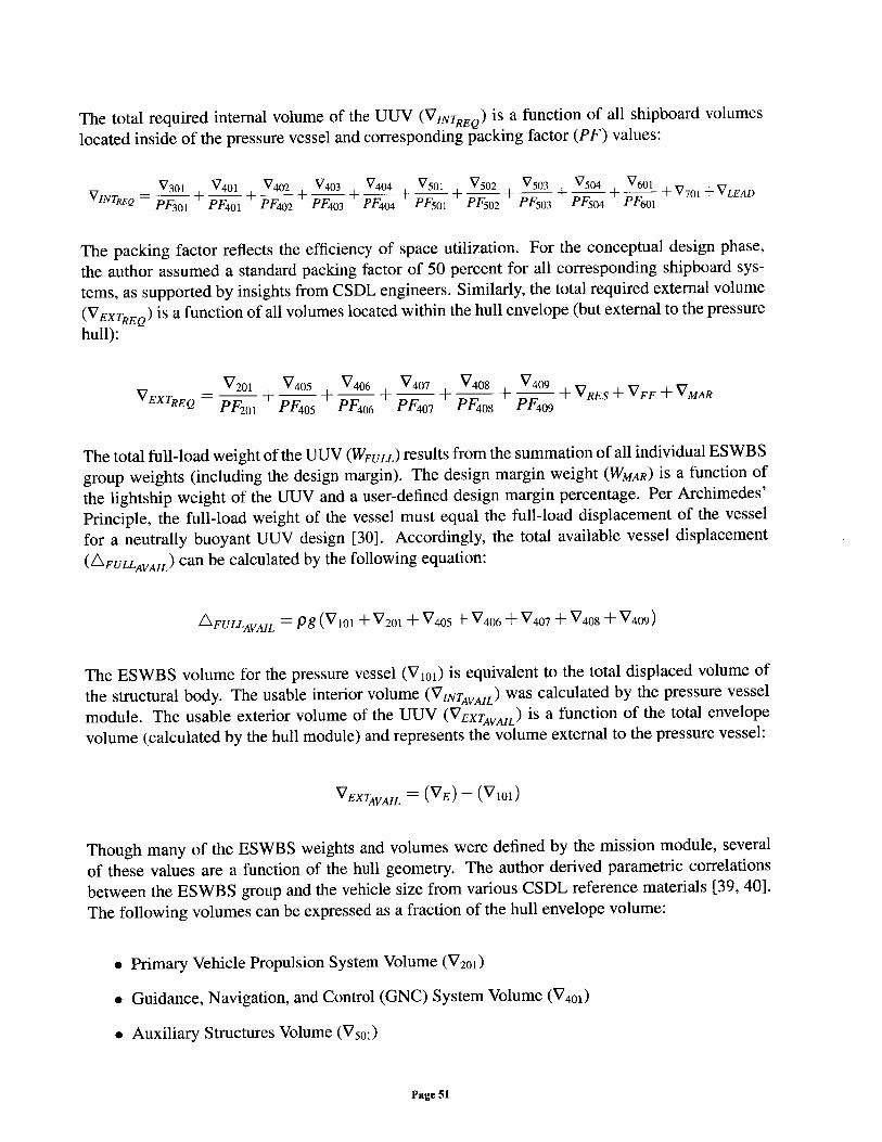
The total required internal volume of the UUV (VINTREQ) is a function of all shipboard volumes
located inside of the pressure vessel and corresponding packing factor (PF) values:
VVNTRE V301 + V401 + V402 +V 403 + V404 + V501 + V502 + V503 + V504 + V601 + V701 - VLEADQ PF 30 1 PF 4 0 1 PF 4 02 PF 4 0 3 PF 4 04 PF 5 0 1 PF 5 0 2 PF 5 0 3 PF 50 4 PF 6 0 1
The packing factor reflects the efficiency of space utilization. For the conceptual design phase,
the author assumed a standard packing factor of 50 percent for all corresponding shipboard sys-
tems, as supported by insights from CSDL engineers. Similarly, the total required external volume
(VEXTREQ) is a function of all volumes located within the hull envelope (but external to the pressure
hull):
VEX = V 201 + V40 5 + V4 06 + + V40 + V4 + V R E S - VFF - VMAREXTREQ PF 20 1 PF 405 PF 406 PF 407 PF 408 PF 4 0 9
The total full-load weight of the UUV (WFULL) results from the summation of all individual ESWBS
group weights (including the design margin). The design margin weight (WMAR) is a function of
the lightship weight of the UUV and a user-defined design margin percentage. Per Archimedes'
Principle, the full-load weight of the vessel must equal the full-load displacement of the vessel
for a neutrally buoyant UUV design [30]. Accordingly, the total available vessel displacement
(AFULLAVAIL) can be calculated by the following equation:
A FULLAVAIL = Pg (V10 1 + V20 1 + V4 05 + V4 06 + V 407 + V408 + V409 )
The ESWBS volume for the pressure vessel (V101) is equivalent to the total displaced volume of
the structural body. The usable interior volume (VINTAVAIL) was calculated by the pressure vessel
module. The usable exterior volume of the UUV (VEXTAVAIL) is a function of the total envelope
volume (calculated by the hull module) and represents the volume external to the pressure vessel:
VEXTAVAIL = (VE) - (V 10 1 )
Though many of the ESWBS weights and volumes were defined by the mission module, several
of these values are a function of the hull geometry. The author derived parametric correlations
between the ESWBS group and the vehicle size from various CSDL reference materials [39, 40].
The following volumes can be expressed as a fraction of the hull envelope volume:
" Primary Vehicle Propulsion System Volume (V201)
" Guidance, Navigation, and Control (GNC) System Volume (V401)
* Auxiliary Structures Volume (V501)
Page 51
e Auxiliary Cabling Volume (V50 2 )
* Primary Ballast System Volume (V50 3 )
" Hull Quieting Material Volume (V60 1 )
* Reserve Volume (VRES)
" Free-Flood Volume (VFF)
" Lead Volume (VLEAD)
Similarly, the weight of the following systems can be expressed as a fraction of the hull envelopedisplacement:
" Guidance, Navigation, and Control (GNC) System Weight (W40 1)
" Auxiliary Structures Weight (W50 1)
* Auxiliary Cabling Weight (W502 )
" Hull Quieting Material Weight (W601)
The weight of the electric motor (W201) can be approximated as a function of shaft horsepower, andthe weight of the primary ballast system (W503) can be expressed as a function of the length-to-diameter ratio of the vehicle. With access to additional research materials (such as previous UUVmodels), the design engineer can easily modify all parametric fractions within the MATLAB code.
The programmed optimization routine (convergence algorithm) assesses the resulting vehicle bal-ance. The algorithm considers three balance functions: the vehicle weight balance, the interiorvolume balance, and the exterior volume balance. The vehicle weight balance parameter (BALw)reflects the existing relationship between the total available vessel displacement and the total full-load weight:
BALw = AFULLAVAIL
WFULL
If the balance parameter is equal to one (or greater), the concept design possesses sufficient dis-placement to support all required shipboard systems. Similarly, the interior volume balance pa-rameter (BALINT) reflects the relationship between the total usable interior volume (VINTAVAIL) andthe total required internal volume of the UUV:
BALINT = VINTAVAIL
VINTREQ
Page 52
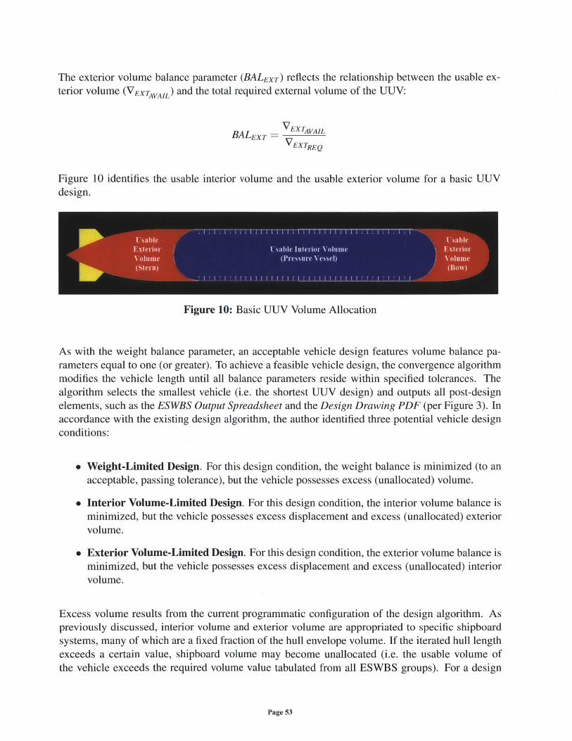
The exterior volume balance parameter (BALEXT) reflects the relationship between the usable ex-terior volume (VEXTAVAIL) and the total required external volume of the UUV:
BALEXT - VEXTAVAIL
VEXTREQ
Figure 10 identifies the usable interior volume and the usable exterior volume for a basic UUVdesign.
Figure 10: Basic UUV Volume Allocation
As with the weight balance parameter, an acceptable vehicle design features volume balance pa-rameters equal to one (or greater). To achieve a feasible vehicle design, the convergence algorithmmodifies the vehicle length until all balance parameters reside within specified tolerances. Thealgorithm selects the smallest vehicle (i.e. the shortest UUV design) and outputs all post-designelements, such as the ESWBS Output Spreadsheet and the Design Drawing PDF (per Figure 3). Inaccordance with the existing design algorithm, the author identified three potential vehicle designconditions:
" Weight-Limited Design. For this design condition, the weight balance is minimized (to anacceptable, passing tolerance), but the vehicle possesses excess (unallocated) volume.
" Interior Volume-Limited Design. For this design condition, the interior volume balance isminimized, but the vehicle possesses excess displacement and excess (unallocated) exteriorvolume.
" Exterior Volume-Limited Design. For this design condition, the exterior volume balance isminimized, but the vehicle possesses excess displacement and excess (unallocated) interiorvolume.
Excess volume results from the current programmatic configuration of the design algorithm. Aspreviously discussed, interior volume and exterior volume are appropriated to specific shipboardsystems, many of which are a fixed fraction of the hull envelope volume. If the iterated hull lengthexceeds a certain value, shipboard volume may become unallocated (i.e. the usable volume ofthe vehicle exceeds the required volume value tabulated from all ESWBS groups). For a design
Page 53
with excess interior volume, unallocated spaces may be redesignated as voids. Similarly, for a
design with excess exterior volume, unallocated spaces may be redesignated as free-flood spaces.Alternatively, the user may consider the integration of unspecified shipboard systems, such asadditional vehicle payloads.
Excess displacement results from the current vehicle iteration mechanism. Because the size of thepressure vessel is directly fixed to the total length of the UUV, a significant increase in the vehiclesize will yield a proportionately large increase in the total displacement of the pressure vessel. Tomitigate the effects of excess displacement, the design algorithm calculates the total weight andtotal volume of lead that must be added to maintain neutral buoyancy. Independent modificationof the pressure vessel size - though not a capability of the current design algorithm - would allowthe user to further refine the displacement of the submersible.
These unique design conditions are a direct function of all customer-defined inputs and the sizeof the modular mission payload. As stated, the length of the vehicle is the primary independentvariable for design iteration. For this thesis, all other variables and principal characteristics areconstant values (or functions of the vehicle length). The MATIAB code could be manipulated tosupport multi-variable design optimization. Ultimately, the balance and optimization routine com-pletes the design spiral and enables iterative development of an acceptable UUV concept design.
Page 54
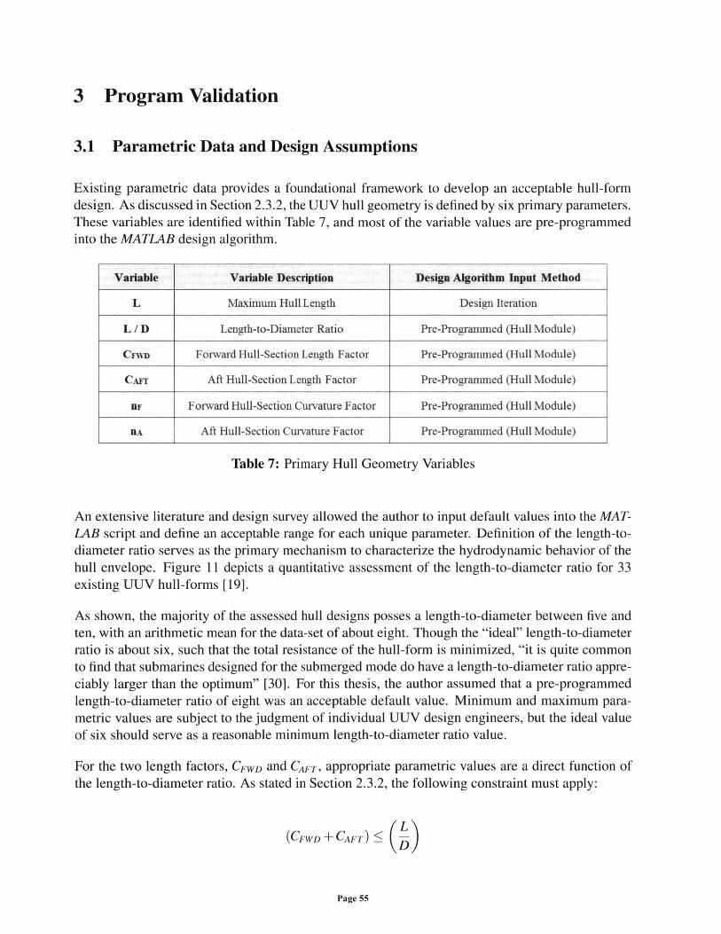
3 Program Validation
3.1 Parametric Data and Design Assumptions
Existing parametric data provides a foundational framework to develop an acceptable hull-formdesign. As discussed in Section 2.3.2, the UUV hull geometry is defined by six primary parameters.These variables are identified within Table 7, and most of the variable values are pre-programmedinto the MATLAB design algorithm.
Variable Variable Description Design Algorithm Input Method
L Maximum Hull Length Design Iteration
L / D Length-to-Diameter Ratio Pre-Programmed (Hull Module)
CnVD Forward Hull-Section Length Factor Pre-Programmed (Hull Module)
CAnr Aft Hull-Section Length Factor Pre-Programmed (Hull Module)
BF Forward Hull-Section Curvature Factor Pre-Programmed (Hull Module)
nA Aft Hull-Section Curvature Factor Pre-Programmed (Hull Module)
Table 7: Primary Hull Geometry Variables
An extensive literature and design survey allowed the author to input default values into the MAT-LAB script and define an acceptable range for each unique parameter. Definition of the length-to-diameter ratio serves as the primary mechanism to characterize the hydrodynamic behavior of thehull envelope. Figure 11 depicts a quantitative assessment of the length-to-diameter ratio for 33existing UUV hull-forms [19].
As shown, the majority of the assessed hull designs posses a length-to-diameter between five andten, with an arithmetic mean for the data-set of about eight. Though the "ideal" length-to-diameterratio is about six, such that the total resistance of the hull-form is minimized, "it is quite commonto find that submarines designed for the submerged mode do have a length-to-diameter ratio appre-ciably larger than the optimum" [30]. For this thesis, the author assumed that a pre-programmedlength-to-diameter ratio of eight was an acceptable default value. Minimum and maximum para-metric values are subject to the judgment of individual UUV design engineers, but the ideal valueof six should serve as a reasonable minimum length-to-diameter ratio value.
For the two length factors, CFWD and CAFT, appropriate parametric values are a direct function ofthe length-to-diameter ratio. As stated in Section 2.3.2, the following constraint must apply:
(CFWD + CAFT) ( ~D
Page 55
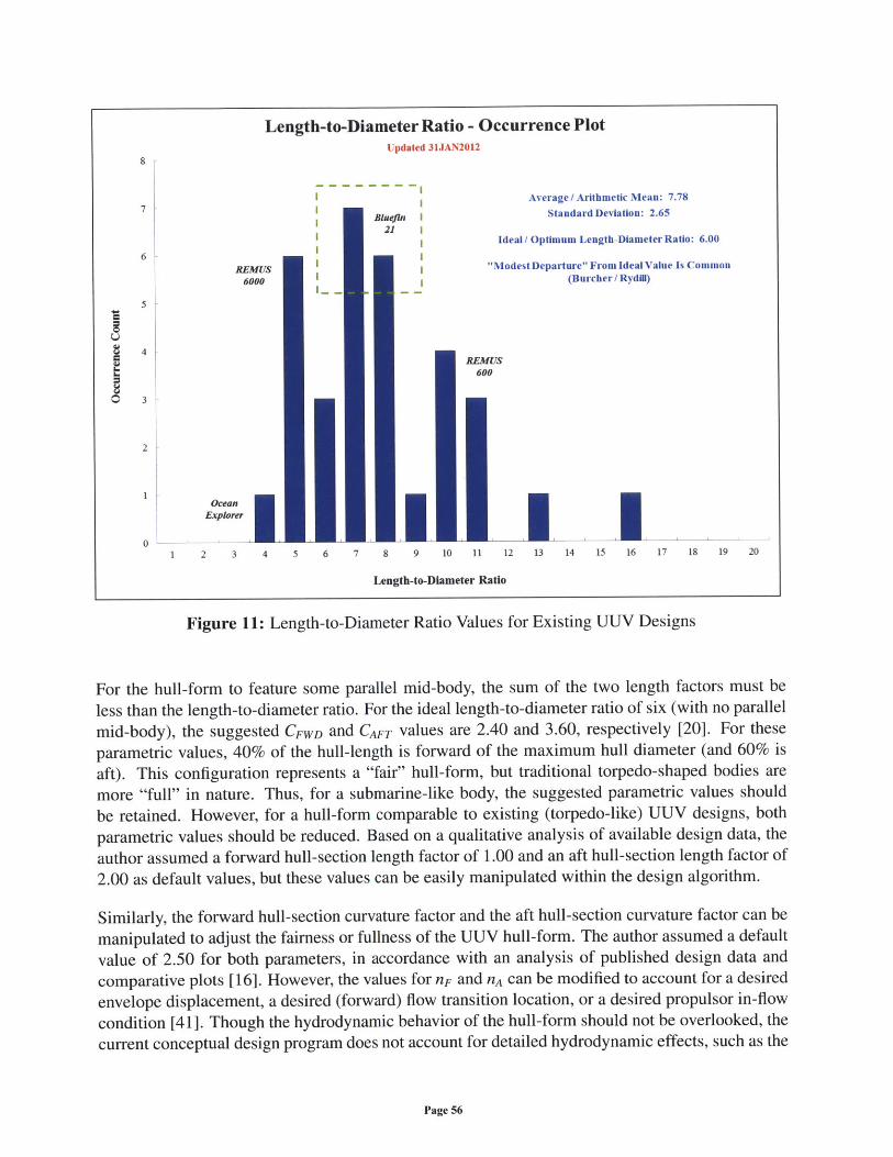
Bluefin I21
Average / Arithmetic Mean: 7.78
Standard Deviation: 2.65
Ideal / Optimum Length-Diameter Ratio: 6.00
"Modest Departure" From Ideal Value Is Common(Burcher / Rydill)
Length-to-Diameter Ratio - Occurrence PlotUpdated 31JAN2012
8
7
6'
5
4
2
02 3 4 5 6 7 8 9 10 11 12 13 14 15 16 17 18 19 20
REMUS600
Length-to-Diameter Ratio
Figure 11: Length-to-Diameter Ratio Values for Existing UUV Designs
For the hull-form to feature some parallel mid-body, the sum of the two length factors must be
less than the length-to-diameter ratio. For the ideal length-to-diameter ratio of six (with no parallel
mid-body), the suggested CFWD and CAFT values are 2.40 and 3.60, respectively [20]. For these
parametric values, 40% of the hull-length is forward of the maximum hull diameter (and 60% isaft). This configuration represents a "fair" hull-form, but traditional torpedo-shaped bodies are
more "full" in nature. Thus, for a submarine-like body, the suggested parametric values should
be retained. However, for a hull-form comparable to existing (torpedo-like) UUV designs, bothparametric values should be reduced. Based on a qualitative analysis of available design data, the
author assumed a forward hull-section length factor of 1.00 and an aft hull-section length factor of2.00 as default values, but these values can be easily manipulated within the design algorithm.
Similarly, the forward hull-section curvature factor and the aft hull-section curvature factor can be
manipulated to adjust the fairness or fullness of the UUV hull-form. The author assumed a defaultvalue of 2.50 for both parameters, in accordance with an analysis of published design data andcomparative plots [16]. However, the values for nF and nA can be modified to account for a desired
envelope displacement, a desired (forward) flow transition location, or a desired propulsor in-flow
condition [41]. Though the hydrodynamic behavior of the hull-form should not be overlooked, thecurrent conceptual design program does not account for detailed hydrodynamic effects, such as the
Page 56
C-
REMUS6000
OceanExplorer
i
1I
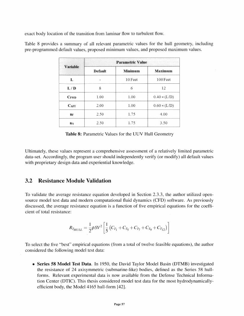
exact body location of the transition from laminar flow to turbulent flow.
Table 8 provides a summary of all relevant parametric values for the hull geometry, includingpre-programmed default values, proposed minimum values, and proposed maximum values.
Table 8: Parametric Values for the UUV Hull Geometry
Ultimately, these values represent a comprehensive assessment of a relatively limited parametricdata-set. Accordingly, the program user should independently verify (or modify) all default valueswith proprietary design data and experiential knowledge.
3.2 Resistance Module Validation
To validate the average resistance equation developed in Section 2.3.3, the author utilized open-source model test data and modern computational fluid dynamics (CFD) software. As previouslydiscussed, the average resistance equation is a function of five empirical equations for the coeffi-cient of total resistance:
RTHULL pSV2 (CT +C +C ,+ CT9 + CT+C2)
To select the five "best" empirical equations (from a total of twelve feasible equations), the authorconsidered the following model test data:
* Series 58 Model Test Data. In 1950, the David Taylor Model Basin (DTMB) investigatedthe resistance of 24 axisymmetric (submarine-like) bodies, defined as the Series 58 hull-forms. Relevant experimental data is now available from the Defense Technical Informa-tion Center (DTIC). This thesis considered model test data for the most hydrodynamically-efficient body, the Model 4165 hull-form [42].
Page 57
Parametric ValueVariable
Default Minimum Maximum
L - 10 Feet 100 Feet
L/D 8 6 12
CnyD 1.00 1.00 0.40 x (L/D)
CA-f 2.00 1.00 0.60 x (L/D)
1F 2.50 1.75 4.00
1A 2.50 1.75 3.50
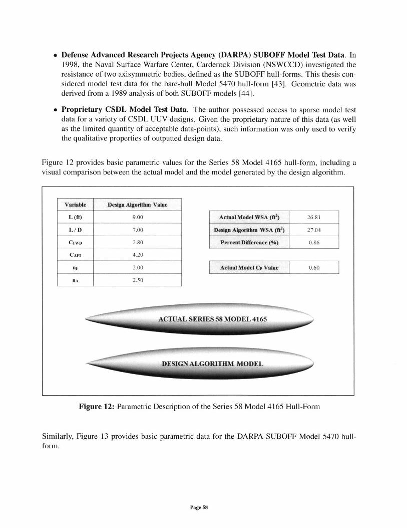
" Defense Advanced Research Projects Agency (DARPA) SUBOFF Model Test Data. In1998, the Naval Surface Warfare Center, Carderock Division (NSWCCD) investigated theresistance of two axisymmetric bodies, defined as the SUBOFF hull-forms. This thesis con-sidered model test data for the bare-hull Model 5470 hull-form [43]. Geometric data wasderived from a 1989 analysis of both SUBOFF models [44].
" Proprietary CSDL Model Test Data. The author possessed access to sparse model testdata for a variety of CSDL UUV designs. Given the proprietary nature of this data (as wellas the limited quantity of acceptable data-points), such information was only used to verifythe qualitative properties of outputted design data.
Figure 12 provides basic parametric values for the Series 58 Model 4165 hull-form, including avisual comparison between the actual model and the model generated by the design algorithm.
Variabl
L (ft)
L/D
CnVD
CAFE
BF
nA
Similarly,form.
e Design Algorithm Value
9.00 Actual Model WSA (f) 2
7.00 Design Algorithm WSA (ff) 2
2.80 Percent Difference (%)
4.20
2.00 Actual Model Ci Value
2.50
ACTUAL SERIES 58 MODEL 4165
Figure 12: Parametric Description of the Series 58 Model 4165 Hull-Form
Figure 13 provides basic parametric data for the DARPA SUBOFF Model 5470 hull-
Page 58
0.60
Variable Design Algorithm Value
L (ft) 14.29
L/D 8.56
CnUD 2.00
C.Arr 2.37
BF 2.40
BA 1.60
Actual Model WSA (ft) 63.72
Design Algorithm WSA (ff2) 64.09
Percent Difference (%) 0.58
Actual Model Cp Value 0.79
ACTUAL DARPA SUBOFF MODEL 5470
DESIGN ALGORITHM MODEL
Figure 13: Parametric Description of the DARPA SUBOFF Model 5470 Hull-Form
As shown, both models are closely approximated by the current design algorithm (using a tradi-tional Jackson hull-form). For each model, the calculated wetted surface-area (WSA) is about onepercent greater than the WSA of the actual hull-form. Though the Series 58 hull-form is closelyreplicated by the design algorithm, the existing design code fails to model the exact stern profileof the SUBOFF hull-form. As such, for the SUBOFF model, the author expected a larger disparitybetween the actual model test data and the predicted model resistance.
Using available model test data for a variety of hull speeds, the difference (6%) between the pre-dicted hull-form resistance and the test data can be calculated by the following equation (as apercentage):
R RTALGORIT HM- RTTEST X 100R TTEST
Accordingly, Table 9 provides a comparative analysis between the model test data and the empirically-derived bare-hull resistance for both geometries. For this comparison, the author assumed a stan-dard roughness allowance (CA) of 0.0004, representing the approximate surface roughness of a"newly painted ship" [45].
Page 59
WWI rT77r7 :71
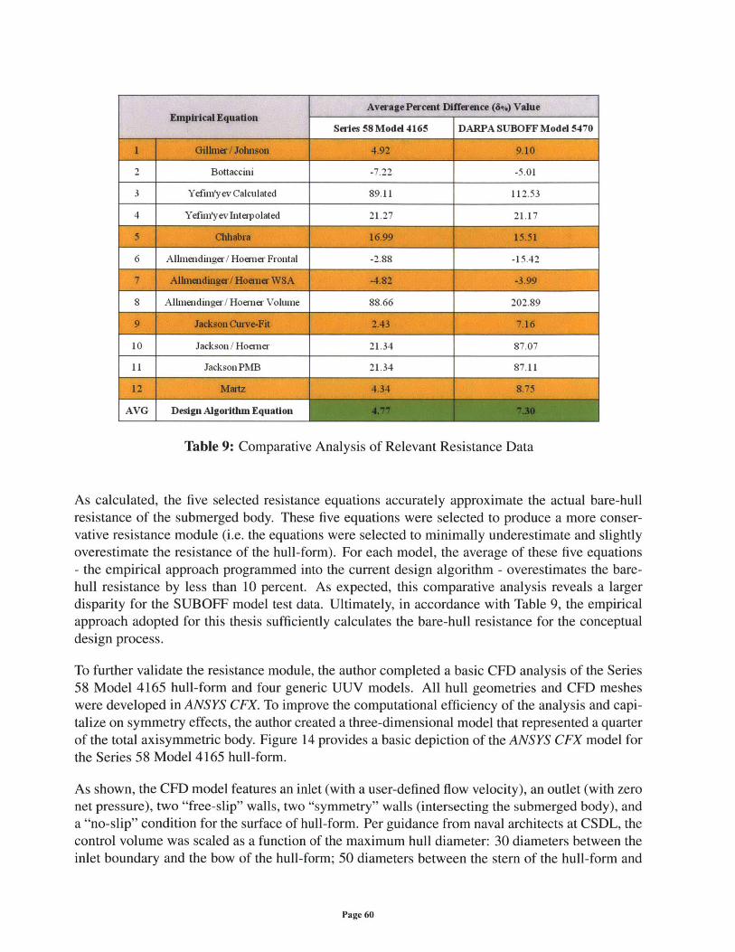
Average Percent Diffeence (84) Value
Series 58 Model 4165 1 DARPA SUBOFF Model 5470
2 Bottaccini -7.22 -5.01
3 Yefim'yev Calcuilated 89.11 112.53
4 Yefim'y ev Interpolated 21.27 121.17
6 Alliendinger / Hoerner Frontal 2.88 15.42
8 Allendinger/ Hoemer Volume 88.66 202.89
10 Jackson / Hoerner 21.34 87.07
11 JacksonPMB 21.34 87.11
Design Algoritun Equation
Table 9: Comparative Analysis of Relevant Resistance Data
As calculated, the five selected resistance equations accurately approximate the actual bare-hullresistance of the submerged body. These five equations were selected to produce a more conser-vative resistance module (i.e. the equations were selected to minimally underestimate and slightlyoverestimate the resistance of the hull-form). For each model, the average of these five equations- the empirical approach programmed into the current design algorithm - overestimates the bare-hull resistance by less than 10 percent. As expected, this comparative analysis reveals a largerdisparity for the SUBOFF model test data. Ultimately, in accordance with Table 9, the empiricalapproach adopted for this thesis sufficiently calculates the bare-hull resistance for the conceptualdesign process.
To further validate the resistance module, the author completed a basic CFD analysis of the Series58 Model 4165 hull-form and four generic UUV models. All hull geometries and CFD mesheswere developed in ANSYS CFX. To improve the computational efficiency of the analysis and capi-talize on symmetry effects, the author created a three-dimensional model that represented a quarterof the total axisymmetric body. Figure 14 provides a basic depiction of the ANSYS CFX model forthe Series 58 Model 4165 hull-form.
As shown, the CFD model features an inlet (with a user-defined flow velocity), an outlet (with zeronet pressure), two "free-slip" walls, two "symmetry" walls (intersecting the submerged body), anda "no-slip" condition for the surface of hull-form. Per guidance from naval architects at CSDL, thecontrol volume was scaled as a function of the maximum hull diameter: 30 diameters between theinlet boundary and the bow of the hull-form; 50 diameters between the stem of the hull-form and
Page 60
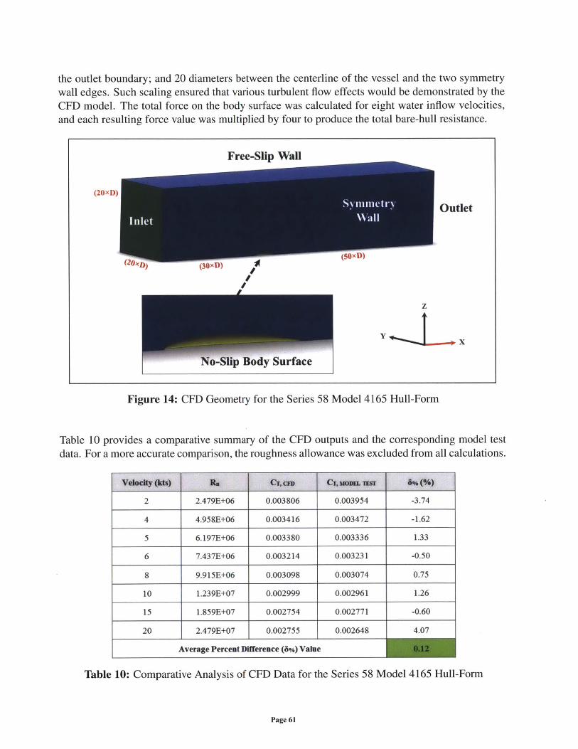
the outlet boundary; and 20 diameters between the centerline of the vessel and the two symmetrywall edges. Such scaling ensured that various turbulent flow effects would be demonstrated by theCFD model. The total force on the body surface was calculated for eight water inflow velocities,and each resulting force value was multiplied by four to produce the total bare-hull resistance.
Figure 14: CFD Geometry for the Series 58 Model 4165 Hull-Form
Table 10 provides a comparative summary of the CFD outputs and the corresponding model testdata. For a more accurate comparison, the roughness allowance was excluded from all calculations.
Velocity (Ms)Ra Cr, cro Cr. ur 8%(%)
2 2.479E+06 0.003806 0.003954 -3.74
4 4.958E+06 0.003416 0.003472 -1.62
5 6.197E+06 0.003380 0.003336 1.33
6 7.437E+06 0.003214 0.003231 -0.50
8 9.915E+06 0.003098 0.003074 0.75
10 1.239E+07 0.002999 0.002961 1.26
15 1.859E+07 0.002754 0.002771 -0.60
20 2.479E+07 0.002755 0.002648 4.07
Average Percent Difference (6%) Value
Model 4165 Hull-Form
Page 61
Free-Slip Wall
-- (50)(D)
Outlet
-P4f
Table 10: Comparative Analysis of CFD Data for the Series 58
(20xD)
) (30xD)
z
Y,* d -X
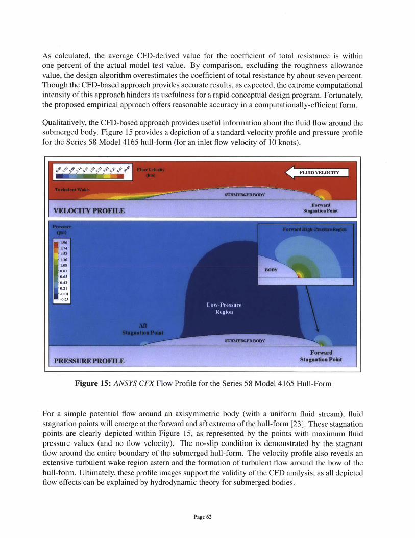
As calculated, the average CFD-derived value for the coefficient of total resistance is withinone percent of the actual model test value. By comparison, excluding the roughness allowancevalue, the design algorithm overestimates the coefficient of total resistance by about seven percent.Though the CFD-based approach provides accurate results, as expected, the extreme computationalintensity of this approach hinders its usefulness for a rapid conceptual design program. Fortunately,the proposed empirical approach offers reasonable accuracy in a computationally-efficient form.
Qualitatively, the CFD-based approach provides useful information about the fluid flow around thesubmerged body. Figure 15 provides a depiction of a standard velocity profile and pressure profilefor the Series 58 Model 4165 hull-form (for an inlet flow velocity of 10 knots).
Figure 15: ANSYS CFX Flow Profile for the Series 58 Model 4165 Hull-Form
For a simple potential flow around an axisymmetric body (with a uniform fluid stream), fluidstagnation points will emerge at the forward and aft extrema of the hull-form [23]. These stagnationpoints are clearly depicted within Figure 15, as represented by the points with maximum fluidpressure values (and no flow velocity). The no-slip condition is demonstrated by the stagnantflow around the entire boundary of the submerged hull-form. The velocity profile also reveals anextensive turbulent wake region astern and the formation of turbulent flow around the bow of thehull-form. Ultimately, these profile images support the validity of the CFD analysis, as all depictedflow effects can be explained by hydrodynamic theory for submerged bodies.
Page 62
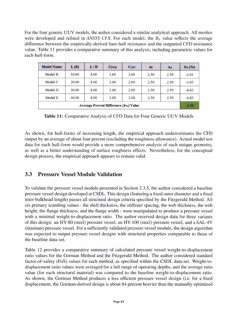
For the four generic UUV models, the author considered a similar analytical approach. All mesheswere developed and refined in ANSYS CFX. For each model, the 3% value reflects the averagedifference between the empirically-derived bare-hull resistance and the outputted CFD resistancevalue. Table 11 provides a comparative summary of this analysis, including parametric values foreach hull-form.
ModelName L(ft) L/D CF" CAr BF BA 6%(%)
Model B 10.00 8.00 1.00 2.00 2.50 2.50 -2.01
Model C 20.00 8.00 1.00 2.00 2.50 2.50 -3.95
Model D 30.00 8.00 1.00 2.00 2.50 2.50 -6.63
Model E 40.00 8.00 1.00 2.00 2.50 2.50 -4.83
Average Percent Difference (8%) Value
Table 11: Comparative Analysis of CFD Data for Four Generic UUV Models
As shown, for hull-forms of increasing length, the empirical approach underestimates the CFDoutput by an average of about four percent (excluding the roughness allowance). Actual model testdata for each hull-form would provide a more comprehensive analysis of each unique geometry,as well as a better understanding of surface roughness effects. Nevertheless, for the conceptualdesign process, the empirical approach appears to remain valid.
3.3 Pressure Vessel Module Validation
To validate the pressure vessel module presented in Section 2.3.5, the author considered a baselinepressure vessel design developed at CSDL. This design (featuring a fixed outer diameter and a fixedinter-bulkhead length) passes all structural design criteria specified by the Fitzgerald Method. Allsix primary scantling values - the shell thickness, the stiffener spacing, the web thickness, the webheight, the flange thickness, and the flange width - were manipulated to produce a pressure vesselwith a minimal weight-to-displacement ratio. The author received design data for three variantsof this design: an HY-80 (steel) pressure vessel, an HY-100 (steel) pressure vessel, and a 6AL-4V(titanium) pressure vessel. For a sufficiently validated pressure vessel module, the design algorithmwas expected to output pressure vessel designs with structural properties comparable to those ofthe baseline data-set.
Table 12 provides a comparative summary of calculated pressure vessel weight-to-displacementratio values for the Gorman Method and the Fitzgerald Method. The author considered standardfactor-of-safety (FoS) values for each method, as specified within the CSDL data-set. Weight-to-displacement ratio values were averaged for a full range of operating depths, and the average ratiovalue (for each structural material) was compared to the baseline weight-to-displacement ratio.As shown, the Gorman Method produces a less efficient pressure vessel design (i.e. for a fixeddisplacement, the Gorman-derived design is about 84 percent heavier than the manually optimized
Page 63
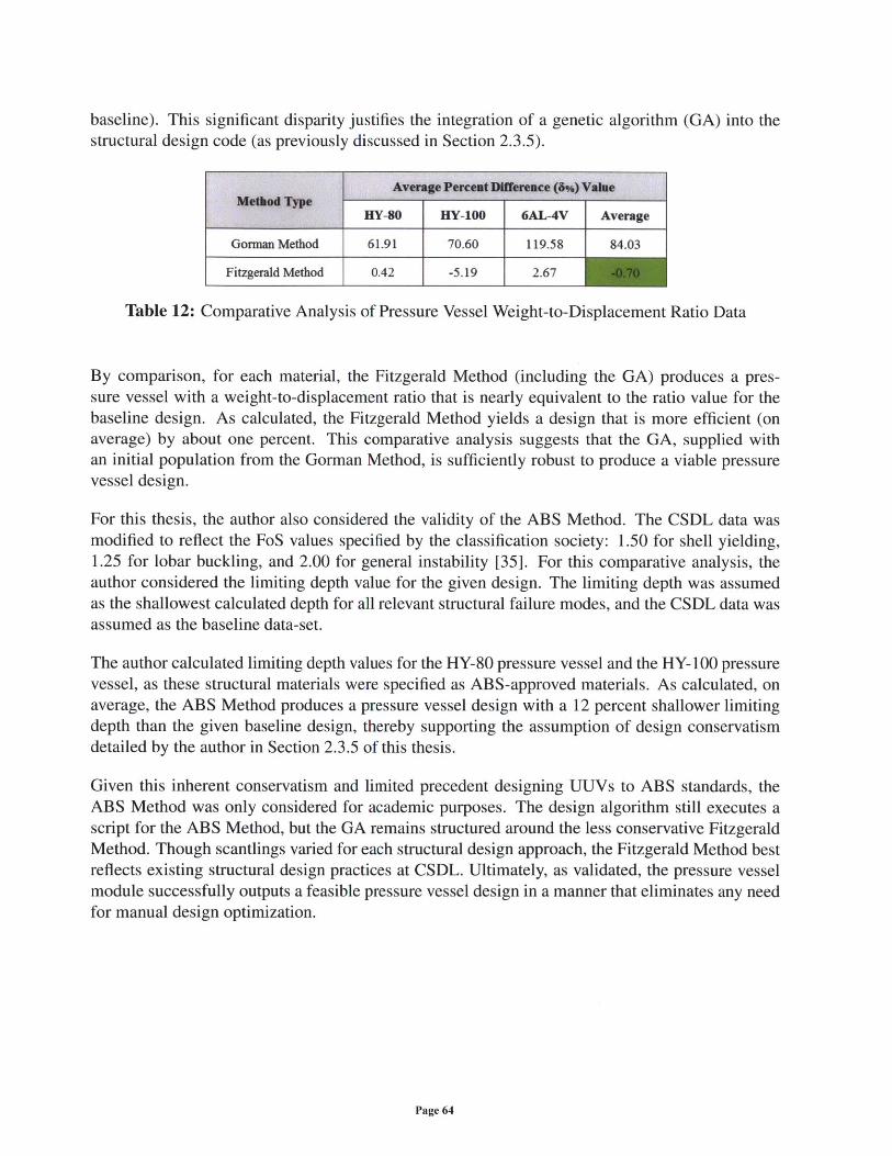
baseline). This significant disparity justifies the integration of a genetic algorithm (GA) into thestructural design code (as previously discussed in Section 2.3.5).
Average Percent Difference (8%) ValueMethd Type
HY-80 HY-100 6AL-4V Average
Gorman Method 61.91 70.60 119.58 84.03
Fitzgerald Method 0.42 -5.19 2.67
Table 12: Comparative Analysis of Pressure Vessel Weight-to-Displacement Ratio Data
By comparison, for each material, the Fitzgerald Method (including the GA) produces a pres-sure vessel with a weight-to-displacement ratio that is nearly equivalent to the ratio value for thebaseline design. As calculated, the Fitzgerald Method yields a design that is more efficient (onaverage) by about one percent. This comparative analysis suggests that the GA, supplied withan initial population from the Gorman Method, is sufficiently robust to produce a viable pressurevessel design.
For this thesis, the author also considered the validity of the ABS Method. The CSDL data wasmodified to reflect the FoS values specified by the classification society: 1.50 for shell yielding,1.25 for lobar buckling, and 2.00 for general instability [35]. For this comparative analysis, theauthor considered the limiting depth value for the given design. The limiting depth was assumedas the shallowest calculated depth for all relevant structural failure modes, and the CSDL data wasassumed as the baseline data-set.
The author calculated limiting depth values for the HY-80 pressure vessel and the HY-100 pressurevessel, as these structural materials were specified as ABS-approved materials. As calculated, onaverage, the ABS Method produces a pressure vessel design with a 12 percent shallower limitingdepth than the given baseline design, thereby supporting the assumption of design conservatismdetailed by the author in Section 2.3.5 of this thesis.
Given this inherent conservatism and limited precedent designing UUVs to ABS standards, theABS Method was only considered for academic purposes. The design algorithm still executes ascript for the ABS Method, but the GA remains structured around the less conservative FitzgeraldMethod. Though scantlings varied for each structural design approach, the Fitzgerald Method bestreflects existing structural design practices at CSDL. Ultimately, as validated, the pressure vesselmodule successfully outputs a feasible pressure vessel design in a manner that eliminates any needfor manual design optimization.
Page 64
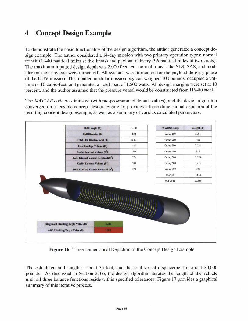
4 Concept Design Example
To demonstrate the basic functionality of the design algorithm, the author generated a concept de-sign example. The author considered a 14-day mission with two primary operation types: normaltransit (1,440 nautical miles at five knots) and payload delivery (96 nautical miles at two knots).The maximum inputted design depth was 2,000 feet. For normal transit, the SLS, SAS, and mod-ular mission payload were turned off. All systems were turned on for the payload delivery phaseof the UUV mission. The inputted modular mission payload weighed 100 pounds, occupied a vol-ume of 10 cubic-feet, and generated a hotel load of 1,500 watts. All design margins were set at 10percent, and the author assumed that the pressure vessel would be constructed from HY-80 steel.
The MATLAB code was initiated (with pre-programmed default values), and the design algorithmconverged on a feasible concept design. Figure 16 provides a three-dimensional depiction of theresulting concept design example, as well as a summary of various calculated parameters.
Huln IAngth (t) 34.70 ESW Grwup Weight(lb)
Hl Diametr (k) 4.34 Group 100 6391
TotalUVDIplaec b 20,400 Group 200 480
T"ta ER OP Voh e () 445 Group 300 7,124
260 Group 400 917
Towa Itera VlUm Rqired 173 Group 500 2,279
UbX ternal V("eln() 188 Group 600 1,425
TOta Eerna Vom Reqire ) 172 Croup 700 100
MarF 1872
Funl-Load 20,588
Figure 16: Three-Dimensional Depiction of the Concept Design Example
The calculated hull length is about 35 feet, and the total vessel displacement is about 20,000pounds. As discussed in Section 2.3.6, the design algorithm iterates the length of the vehicleuntil all three balance functions reside within specified tolerances. Figure 17 provides a graphicalsummary of this iterative process.
Page 65
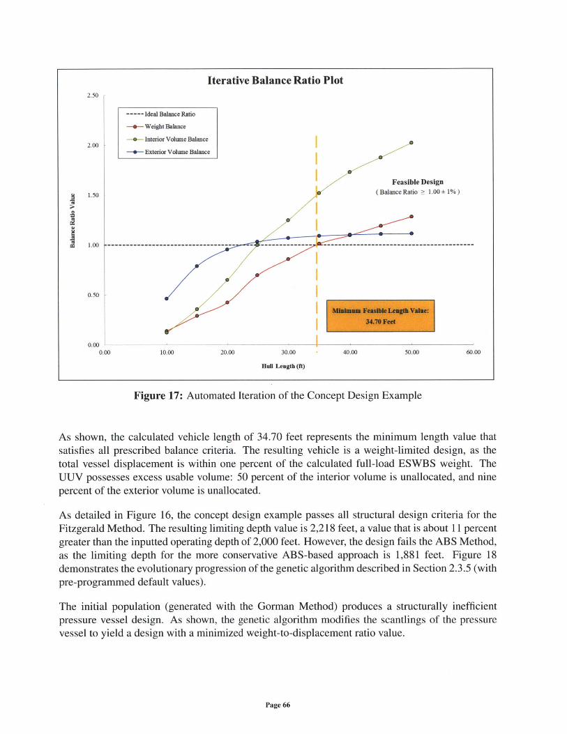
Iterative Balance Ratio Plot2.50
- Ideal Balance Ratio
- Weight Balance
2.00 Interior Volume Balance
- Exterior Volume Balance
Feasible Design
1.50 (Balance Ratio > 1.00 1%)
cc 1.00 ------------------------------------ -------------------------------------------------------------
0.50
0.000.00 10.00 20.00 30.00 40.00 50.00 60.00
Hug Length (ft)
Figure 17: Automated Iteration of the Concept Design Example
As shown, the calculated vehicle length of 34.70 feet represents the minimum length value thatsatisfies all prescribed balance criteria. The resulting vehicle is a weight-limited design, as thetotal vessel displacement is within one percent of the calculated full-load ESWBS weight. TheUUV possesses excess usable volume: 50 percent of the interior volume is unallocated, and ninepercent of the exterior volume is unallocated.
As detailed in Figure 16, the concept design example passes all structural design criteria for theFitzgerald Method. The resulting limiting depth value is 2,218 feet, a value that is about 11 percentgreater than the inputted operating depth of 2,000 feet. However, the design fails the ABS Method,as the limiting depth for the more conservative ABS-based approach is 1,881 feet. Figure 18demonstrates the evolutionary progression of the genetic algorithm described in Section 2.3.5 (withpre-programmed default values).
The initial population (generated with the Gorman Method) produces a structurally inefficientpressure vessel design. As shown, the genetic algorithm modifies the scantlings of the pressurevessel to yield a design with a minimized weight-to-displacement ratio value.
Page 66
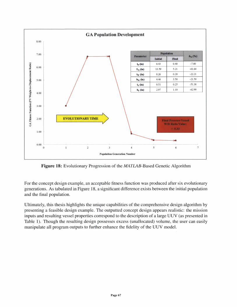
Figure 18: Evolutionary Progression of the MATLAB-Based Genetic Algorithm
For the concept design example, an acceptable fitness function was produced after six evolutionarygenerations. As tabulated in Figure 18, a significant difference exists between the initial populationand the final population.
Ultimately, this thesis highlights the unique capabilities of the comprehensive design algorithm bypresenting a feasible design example. The outputted concept design appears realistic: the missioninputs and resulting vessel properties correspond to the description of a large UUV (as presented inTable 1). Though the resulting design possesses excess (unallocated) volume, the user can easilymanipulate all program outputs to further enhance the fidelity of the UUV model.
Page 67
GA Population Development8.00
7.00
t, (1n) 0.43 0.40 -7.006.00Ls ) 13.59 5.21 -61.64
E ~tw (in) 0.26 0.20 -22.21
5.00 hwV (in) 4.46 3.50 -21.50
tF (in) 0.51 0.25 -51.38
bE (in) 2.97 1.10 -62.994.00
T
3.00
2.00 EVOLUTIONARY TIME
1.00
0.000 1 2 3 4 5 6 7
Population Generation Number
5 Conclusion
5.1 Thesis Summary
This thesis presents a unique, MATLAB-based approach to the conceptual design process for un-manned underwater vehicles. The developed algorithm features five primary modules: a missionmodule, a hull module, a resistance module, a battery module, and a pressure vessel module. De-sign iteration occurs as a function of hull length, such that the resulting UUV possesses sufficientdisplacement, interior volume, and exterior volume. All modules were created by consolidatingopen-source information and experiential knowledge into well-organized MATLAB scripts. Theresistance module was validated by model test data and CFD analysis, and the pressure vesselmodule was validated by a comparison to manually optimized designs developed at CSDL.
The resulting design algorithm represents a sufficient, reliable, and versatile computational tool,in accordance with the proposed design philosophy for this thesis. The outputted concept designpossesses sufficient fidelity to inform UUV design engineers and strategic decision-makers, en-abling rapid exploration of the UUV design space for a given set of customer inputs. Ultimately,this conceptual design program supports United States Navy efforts to develop UUVs for sus-tained operations in contested A2/AD environments, thereby supporting the strategic shift to theAsia-Pacific region.
5.2 Recommendations and Future Research Efforts
For generations, UUV technology has served at the forefront of the maritime battlespace, but theacquisition of such systems remains challenged by the limited availability of published design dataand automated design tools. For the United States Navy, the conceptual design process serves toexplore a given design space and facilitate a comprehensive analysis-of-alternatives (AoA), en-suring that taxpayer resources are well allocated. For a given set of requirements, the Navy isobligated to consider the best practices of naval architecture, marine engineering, ocean engineer-ing, and systems engineering to produce a feasible vehicle design. Accordingly, the author offersthe following recommendations:
" The United States Navy should continue to invest in early-stage conceptual design programs,such as the MATLAB-based design tool presented in this thesis. However, these design al-gorithms must be developed by practicing naval architects and ocean engineers, such thatoutputted vehicle designs reflect the best practices of the UUV design industry. Increasedinvestment in the conceptual design process would improve the affordability and efficiencyof major UUV acquisition programs.
" The United States Navy, through the Naval Undersea Warfare Center (NUWC), should de-velop a comprehensive database of UUV designs, including principal characteristics, modeltest data, CFD outputs, structural analysis results, and cost estimates. Such a database should
Page 68
be accessible to active-duty naval officers, design engineers, and industry partners. A com-
prehensive UUV design database would encourage the development of advanced UUV de-sign tools and enable future crowd-sourcing efforts.
* The United States Navy should better support educational programs focused on UUV andsubmersible design efforts, including courses offered at the United States Naval Academy(USNA), the Naval Postgraduate School (NPS), the Massachusetts Institute of Technology(MIT), and other civilian institutions. A dedicated cadre of active-duty naval officers shouldbe encouraged to study the entire UUV design process, and the Navy should encourage thetransfer of experiential knowledge from retiring naval architects to this new generation ofUUV design engineers. Such efforts would better prepare the United States Navy for thenext generation of undersea warfare.
Though this thesis produced a functional design algorithm, additional research would enhance the
capability of the conceptual design program. For each module, the author proposes the following:
" Mission Module. Future research should support the development of an improved customerinterface and better identify the full spectrum of anticipated user inputs.
" Hull Module. Future research should support the integration of alternative hull-form designsand better explore the existing design variables for the Jackson hull-form. Design curvesshould be developed to present the principal characteristics of the resulting UUV design asa function of pre-programmed parameters, such as length-to-diameter ratio values, lengthfactors, and curvature factors.
" Resistance Module. Future research should support the consideration of additional modeltest data and better integration with CFD software programs. The empirical resistance equa-tions presented in this thesis should be validated with tow-tank data for unusual, algorithm-generated hull models.
" Battery Module. Future research should better integrate modern advances in UUV batterytechnology, including efforts to develop fuel-cell systems for UUVs.
" Pressure Vessel Module. Future research should consider FEA to further validate the pres-
sure vessel module. Additionally, genetic algorithms should be developed for the ABSMethod and other preferred classification standards, such as those specified by Germanis-cher Lloyd (GL) [46].
The cumulative design program would benefit from the development of improved graphic user
interfaces, including interfaces that would enable the modification of vessel general arrangements
and better presentation of outputted design data. Ultimately, the UUV conceptual design programdeveloped for this thesis possesses sufficient flexibility and modularity to rapidly integrate all fu-
ture research activities. The author strongly encourages any interested naval officers, students,and researchers to collaborate with The Charles Stark Draper Laboratory (CSDL) to improve the
design algorithm and better explore the naval architecture of advanced submersible design.
Page 69
Appendix A: Alternative Design Options
This appendix discusses alternative design options for some of the modules discussed in previoussections of this thesis document.
Hull Module
As presented in Section 2.3.2 of this thesis, the current design algorithm uses a standard Jacksonhull-form as the default hull geometry. Though the Jackson hull-form reflects the hull envelope ofmany modern submersibles, the conceptual design program would benefit from the considerationof alternative hull geometries. To improve the stern profile of the vessel, the author recommendsan axisymmetric geometry defined as a "Myring" hull-form [47].
The Myring hull-form is a function of five independent variables: the length of the forward hull-section (a), the length of the parallel mid-body (b), a forward hull-section curvature index (n), the"tail semi-angle" (a), and the maximum hull-form diameter (d). As specified, "all dimensionsare referred to the overall body length which is taken to be 100 units," and the tail semi-angle ismeasured in degrees (as an angle from the centerline axis of the vessel) [47]. Accordingly, thelength of the aft hull-section (LTAIL) is given by the following equation:
LTAIL= 100- (a+b)
For a given axial coordinate (x), the radius of the forward hull-section (rNOSE) is defined by thefollowing equation for a "modified semi-ellipsoid":
rNOSE ~() { - )2
The radius of the aft hull-section (rTAIL) is given by the following equation:
TTAIL = - { 3d - tan(a) [x-a-b]2 + d an3 ( ) j [x-a-b]3}2) 2 (LTAIL LTAIL I(LTAIL)3 (LTAIL)2
The Myring hull-form is comparable (in appearance) to the Jackson hull-form, but considerationof the tail semi-angle allows for the UUV design engineer to better account for stern flow effectsresulting from the geometry of the hull envelope. Though this alternative hull geometry was notprogrammed into the proposed design algorithm, the Myring hull-form may prove beneficial tonaval architects and hydrodynamicists studying the interactions between modern propulsor systemsand unusual stern configurations.
Page 70
Resistance Module
As discussed in Section 2.3.3, the shaft horsepower (SHP) of a UUV is a function of the effectivehorsepower (EHP) at a given operating speed and a propulsive coefficient (PC) value:
SHEP = HPSP
The current design algorithm uses a pre-programmed propulsive coefficient value, but this coeffi-cient can be estimated by considering the geometry of the UUV hull-form and historic propellerdesign data. For the conceptual design process, the author recommends data for a standard pro-peller series, such as the Wageningen B-Screw Series (as tested at the Naval Surface WarfareCenter) [48]. The propulsive coefficient can be calculated by the following equation [49]:
PC = (THULL) (71RR) (qPROP)
For this thesis, the author recommends a standard relative rotative efficiency (71RR) value of 1.03 fora "single-screw" propeller design [16]. The hull efficiency (71HULL) can be expressed as a functionof the thrust deduction fraction (t) and the wake fraction (w):
1 -t77HULL -
Jackson suggests the following equation to approximate the value of the thrust deduction term(1 - t), as a function of the maximum propeller diameter (DpRop) and the wetted surface-area ofthe hull-form (S):
(1 -t) = 0.632+ 2.44 DPROP
Similarly, the value of the wake fraction term (1 - w) can be approximated by the following equa-tion:
(1 - w) = 0.371+ 3.04 x DpRop
As the diameter of the propeller should not exceed the maximum diameter of the hull envelope(D), the author recommends the following range for a feasible propeller diameter:
(0.50 x D) ; DPROP < D
Page 71
The UUV design engineer should strive to maximize the diameter of the propeller, such that thethrust, torque, and efficiency of the propeller design are sufficiently considered. The propellerefficiency (77PRoP) can be approximated from open-water design data for the Wageningen B-ScrewSeries. For such an approximation, the design engineer should calculate the thrust coefficient at aspecific operating point (KTO), as given by the following equation:
= [EHP] ~ 550 ~ [j 2
rOP _V . p (DPROP2 X1t)1W2
This thrust coefficient value is a function of the specified operating velocity (V), the effective horse-power at that velocity (as calculated in Section 2.3.3), the mass-density of water (p), the maximumpropeller diameter, the thrust deduction term, the wake fraction term, and a non-dimensional ad-vance coefficient (J) term. For the specified Wageningen B-Screw Series data, the operating thrustcoefficient should be plotted as a function of the advance coefficient for the following range ofvalues:
0.10 < J < 1.50
Accordingly, to determine the propeller efficiency, this KTO plot should be compared to a plot ofthe actual thrust coefficient (KT) data for a given Wageningen B-Screw Series design (as a functionof similar advance coefficient values). Per the open-water test data provided by the Naval Sur-face Warfare Center (NSWC), thrust coefficient values can be calculated for 14 different propellerdesigns [48]. These "B-Series" propellers are defined by three principal parameters: the pitch-to-diameter ratio (s), the expanded-area ratio (EAR), and the number of propeller blades (Z). Thethrust coefficient can be calculated by the following equation:
KT = (C4sm) X (J x x (EAR)' x (Z)j
Similarly, the non-dimensional torque coefficient (KQ) can be calculated by the following equation:
KQ = ( a)(J) X (§ ) x (EAR)r x (Z)
Values for five non-dimensional terms - s, t, U, ', and C - are detailed in tabular format withinthe NSWC reference (for both the thrust coefficient and the torque coefficient). A plot of KT (asa function of J) should be superimposed on the plot of the KTO values, and the design engineershould identify the J value at which the KTo curve intersects the KT curve. Accordingly, usingthe open-water test data for that derived J value (and the two previous equations), the open-waterpropeller efficiency can be calculated by the following equation:
Page 72
7IPROP (A) (K)
Ultimately, this procedure provides a mechanism to approximate the propulsive coefficient value
for a UUV that features a Wageningen B-Screw Series propeller design. Though the current de-
sign algorithm does not include such calculations, the prescribed procedure could significantly
enhance the fidelity of the resistance module. Undoubtedly, the consideration of alternative pro-
peller geometries (and corresponding open-water data) would further support the proposed UUVconceptual design program.
Page 73
References
[1] "Sustaining U.S. Global Leadership: Priorities for 21st Century Defense," DoD, January2012.
[2] A. S. Erikson, et al., Eds., China's Future Nuclear Submarine Force. Annapolis, MD: NavalInstitute Press, 2007.
[3] N. Freier, "The Emerging Anti-Access/Area-Denial Challenge," CSIS, Washington, DC, May2012.
[4] Quadrennial Defense Review Report, DoD, February 2010.
[5] The Navy Unmanned Undersea Vehicle (UUV) Master Plan, DoN, November 2004.
[6] R. W. Button, et al., "A Survey of Missions for Unmanned Undersea Vehicles," RAND, SantaMonica, CA, 2009.
[7] Unmanned Systems Integrated Roadmap FY2011-2036, DoD, 2011.
[8] K. J. Tokarick, "Employment Considerations in the Use of Unmanned Undersea Vehicles bythe Operational Commander," Naval War College, Newport, RI, May 2005.
[9] "Guidance for Developing Maritime Unmanned Systems (MUS) Capability," NATO CJOSCOE, Norfolk, VA, July 2012.
[10] E. E. Allmendinger, Ed., Submersible Vehicle Systems Design. Jersey City, NJ: SNAME,1990.
[11] Fiscal Year 2013 Department of the Navy Budget Materials [Online]. Available:http://www.finance.hq.navy.mil/fmb/13pres/books.htm
[12] J. F. Schank, et al., "Sustaining U.S. Nuclear Submarine Design Capabilities," RAND, SantaMonica, CA, 2007.
[13] T. Lamb, Ed., Ship Design and Construction: Volume I. Jersey City, NJ: SNAME, 2003.
[14] A. Kossiakoff, et al., Systems Engineering Principles and Practice. Hoboken, NJ: Wiley,2011.
[15] D. G. M. Watson, Practical Ship Design. Oxford, United Kingdom: Elsevier, 1998.
[16] H. A. Jackson, "Submarine Design Notes," MIT Professional Summer, June 1993.
[17] Weight Estimating and Margin Manual for Marine Vehicles, SAWE, May 2001.
[18] Work Breakdown Structure for Defense Materiel Items, DoD MIL-STD-881C, October 2011.
[19] C. Hollosi, Jane's Unmanned Maritime Vehicles and Systems. Alexandria, VA: Jane's Infor-mation Group, 2011.
Page 74
[20] H. A. Jackson, "Fundamentals of Submarine Concept Design," SNAME Transactions, Vol-ume 100, 1992.
[21] T. C. Gillmer and B. Johnson, Introduction to Naval Architecture. Annapolis, MD: NavalInstitute Press, 1982.
[22] L. Larsson and H. C. Raven, The Principles of Naval Architecture Series: Ship Resistanceand Flow. Jersey City, NJ: SNAME, 2010.
[23] J. N. Newman, Marine Hydrodynamics. Cambridge, MA: MIT Press, 1977.
[24] M. R. Bottaccini, "The Stability Coefficients of Standard Torpedoes," DoN, China Lake, CA,NAVORD Report 3346, 1954.
[25] N. N. Yefim'yev, Fundamentals of Submarine Theory. Moscow, USSR: Military PublishingHouse, 1965.
[26] V. M. Bukalov and A. A. Narusbayev, Atomic-Powered Submarine Design. Leningrad,USSR: Shipbuilding Publishing House, 1964.
[27] N. K. Chhabra, "Dry UUV Design Spreadsheet," CSDL, September 2011.
[28] S. F. Hoerner, Fluid-Dynamic Drag. Bakersfield, CA: Hoerner Fluid Dynamics, 1965.
[29] M. A. Martz, "Preliminary Design of an AUV Using a Multiple-Objective Genetic Opti-mizer," M.S. Thesis, Ocean Engineering, Virginia Tech, Blacksburg, VA, 2008.
[30] R. Burcher and L. Rydill, Concepts in Submarine Design. Cambridge, United Kingdom:Cambridge University Press, 1994.
[31] A. F. Molland and S. R. Turnock, Marine Rudders and Control Surfaces. Oxford, UnitedKingdom: Elsevier, 2007.
[32] G. Griffiths, Ed., Technology and Applications of Autonomous Underwater Vehicles. NewYork, NY: Taylor & Francis, 2003.
[33] J. P. Comstock, Ed., Principles of Naval Architecture. New York, NY: SNAME, 1967.
[34] W. C. Young, et al., Roark's Formulas for Stress and Strain. New York, NY: McGraw-Hill,2012.
[35] ABS Rules for Building and Classing Underwater Vehicles, Systems, and Hyperbaric Facili-ties, ABS, 2012.
[36] L. A. Gish, "Analytical and Numerical Study of Underwater Implosion," Ph.D. Thesis De-fense, MIT, April 2013.
[37] J. J. Gorman and L. Louie, "Submersible Pressure Hull Design Parametrics," SNAME, JerseyCity, NJ, 1991.
Page 75
[38] C. R. Houck, et al., "A Genetic Algorithm for Function Optimization: A MATLAB Imple-mentation," North Carolina State University, 1996.
[39] A. C. Edsall, et al., "Advanced Vehicle Concept (AVC) Study Final Report," CSDL, Cam-bridge, MA, CSDL-R-2489, March 1993.
[40] P. A. Kerrebrock and T. G. Ogrodnik, "Long-Term Mine Reconnaissance System VehicleArchitecture Study," CSDL, Cambridge, MA, CSDL-R-2689, July 1995.
[41] C. L. Warren and M. W. Thomas, "Submarine Hull-Form Optimization Case Study," NavalEngineers Journal, November 2000.
[42] M. Gertler, "Resistance Experiments on a Systematic Series of Streamlined Bodies of Revo-lution - For Application to the Design of High-Speed Submarines," DTMB, Washington, DC,Report C-297, April 1950.
[43] H. L. Liu and T. T. Huang, "Summary of DARPA SUBOFF Experimental Program Data,"NSWCCD, West Bethesda, MD, CRDKNSWC/HD-1298-11, June 1998.
[44] N. C. Groves, et al., "Geometric Characteristics of DARPA SUBOFF Models," DTRC,Bethesda, MD, DTRC/SHD-1298-01, March 1989.
[45] T. A. Shapiro, "The Effect of Surface Roughness on Hydrodynamic Drag and Turbulence,"USNA, Annapolis, MD, Trident Scholar Report 327, 2004.
[46] Rules for Classification and Construction, Underwater Technology, Unmanned Submersiblesand Underwater Working Machines, GL, 2009.
[47] D. F. Myring, "A Theoretical Study of the Effects of Body Shape and Mach Number on theDrag of Bodies of Revolution in Subcritical Axisymmetric Flow," MoD, Farnborough, UK,Technical Report 81005, January 1981.
[48] R. F. Roddy, et al., "Neural Network Predictions of the 4-Quadrant Wageningen PropellerSeries," NSWCCD, West Bethesda, MD, NSWCCD-50-TR-2006/004, April 2006.
[49] R. Bhattacharyya, "Resistance and Propulsion (EN353) Lecture Notes," USNA, 2010.
Page 76