Embed Size (px)
Citation preview
DEÜ FMD 23(69), 893-901, 2021
893
1 Ege Üniversitesi, Mühendislik Fakültesi, Makine Mühendisliği Bölümü, İzmir, TÜRKİYE Sorumlu Yazar / Corresponding Author *: [email protected]
Geliş Tarihi / Received: 20.11.2020
Kabul Tarihi / Accepted: 08.02.2021
Araştırma Makalesi/Research Article
DOI:10.21205/deufmd.2021236917
Atıf şekli/ How to cite: TURGUT M.S.(2021). Development and Validation of a Dynamic Vapor Compression Cycle Model. DEUFMD 23(69), 893-
901.
Abstract
Heating, ventilation and air conditioning systems have widespread household and industrial applications and play a leading role in the energy consumption of countries around the world. By analyzing the dynamic behavior of these systems, it is possible to make them operate more efficiently. In this study, the dynamic behavior of a vapor compression cycle is analyzed. The evaporator and condenser are modeled with the finite-difference method and the expansion valve and compressor are modeled with static relationships. Gungor-Winterton and Travis et al. correlations are, respectively used as the evaporation and condensation correlations. The expansion valve openness and compressor motor speed are selected as the input variables to the system. Another model with the same design specifications is developed in the SimulationX environment to verify the proposed model. Both models are perturbed with the two input variables with varying values over constant intervals and the transient behavior of the system is investigated. The results showed that the outcomes of the two models agree well with each other. The largest prediction difference is observed as 2x10⁻⁴ kg/sec. for the mass flow rates and 1.4 K for the heat exchangers inlet temperatures.
Keywords: Thermodynamics, Vapor Compression Cycles, Dynamic Simulation
Öz
Mert Sinan Turgut *1
Isıtma, havalandırma ve iklimlendirme sistemlerinin sanayide ve konutlarda bir çok uygulaması bulunmakta ve dünya etrafındaki ülkelerin enerji tüketiminde büyük bir rol oynamaktadır. Bu sistemlerin dinamik davranışları analiz edilerek daha verimli çalışılmaları sağlanılabilir. Bu çalışmada bir buhar sıkıştırma çevriminin dinamik davranışı analiz edilmiştir. Evaporatör ve kondenser sonlu farklar yöntemiyle, genleşme vanası ve kompresör ise statik denklemlerle modellenmiştir. Evaporasyon ve kondensasyon korelasyonları olarak sırasıyla Gungor-Winterton ve Travis vd. korelasyonları kullanılmıştır. Genleşme vanası açıklığı ve kompresör motor hızı sisteme girdi değişkenleri olarak seçilmiştir. Önerilen sistemin doğrulanması için aynı dizayn özelliklerine sahip başka bir model SimulationX ortamında oluşturulmuştur. İki model de seçilen girdi değişkenlerinin belirli sürelerle değişen farklı değerine simülasyon zamanı boyunca maruz bırakılmış ve sistemlerin dinamik davranışları gözlenmiştir. Elde edilen sonuçlar iki modelin çıktılarının benzer olduğunu
Development and Validation of a Dynamic Vapor Compression Cycle Model
Bir Dinamik Buhar Sıkıştırma Çevrimi Modelinin Geliştirilmesi ve Doğrulanması

DEÜ FMD 23(69), 893-901, 2021
894
göstermiştir. En büyük tahmin farkı ısı değiştirgeci giriş sıcaklıklarında 1.4 K, kütlesel debilerde ise 2x10⁻⁴ kg/sn olarak gözlenmiştir.
Anahtar Kelimeler: Termodinamik, Soğutma Çevrimleri, Dinamik Simülasyon
1. Introduction
HVAC systems are widely used in industry and residences and responsible for a significant amount of energy consumption of the countries around the world. HVAC systems represented 30% of the annual energy consumption of commercial buildings in 2017, which is 5.35 quadrillion Btu/year, according to the US Department of Energy [1]. One of the leading objectives of the researchers has been reducing the energy consumption of the HVAC systems by analyzing their transient behavior[2]. Moreover, analyzing the transient behavior of the HVAC systems is an integral part of the optimization and control of such systems.
Some of the leading studies about the transient behavior of the vapor compression cycles are accomplished by American National Standards Bureau. The steady-state and transient behavior of a vapor compression cycle [3] and boiler [4] are investigated in these studies. Chi and Didion [5] developed a software named TRPUMP that can achieve the dynamic simulation of their experimental heat pump setup. The researchers included the component models to the software in lumped parametric form. As a result of this study, it is realized that the outcomes of the software agreed well with the experimental readings. Bonne et al. [6] investigated the transient simulation of an electric motor-driven heat pump and studied the system performance with an on-off control compressor. MacArthur [1] developed a dynamic model for a vapor compression cycle. The author presented different modeling approaches for each component in the cycle, namely evaporator, condenser, accumulator, expansion device and compressor, and discussed their solution strategies. At the end of this study, the author realized that the predictions of the dynamic model agree well with the experimental outcomes. Chen and Lin [7] proposed a novel method of optimal matching to reduce the energy consumption of a small-scale refrigeration system. The authors developed a transient simulation model of a vapor compression cycle consists of an evaporator,
condenser, compressor and expansion valve. Afterward, the authors introduced their optimal matching method between the cycle components to reduce energy consumption. The authors realized that their optimal matching strategy resulted in 5.1% drop in energy consumption of the cycle. Fu et al. [8] introduced a dynamic model for a air-to-water dual-mode heat pump with screw compressor. The authors realized that the simulated results are in good agreement with the experimental data and the developed model can be utilized as a tool for the product development.
Rasmussen and Alleyne [9] investigated various methods for the dynamical simulation of the vapor compression cycle and its components. The authors verified their developed nonlinear model with the experimental data. Furthermore, the authors presented a theoretical framework for designing gain scheduled controllers for the control of vapor compression cycles. Rasmussen and Shenoy [10] introduced dynamic modeling approaches for vapor compression systems and their individual components. For the two-phase heat exchangers, the authors proposed examples for both finite control volume and moving boundary approaches. Moreover, the authors verified an example developed model with the experimental data.
This study considers the dynamic modeling of a vapor compression cycle. R134a and water are respectively utilized as the primary and secondary fluids of the cycle. The evaporator and condenser are modeled with the finite difference method and the compressor and expansion valve are modeled with static relationships. Gungor and Winterton [11] and Travis et al. [12] are respectively utilized as the evaporation and condensation correlations in the evaporator and condenser. Müller-Steinhagen and Heck [13] correlation is used to model the two-phase pressure drop that occurs in the heat exchangers. The developed model is perturbed with two input variables, namely the expansion valve openness and compressor motor speed, with varying values over constant intervals and the obtained results are compared with that of

DEÜ FMD 23(69), 893-901, 2021
895
SimulationX [14] model with the same design specifications. Outcomes of the developed model showed a good agreement with that of the SimulationX model.
The rest of the paper is considered as follows. Mathematical models of each component in the cycle are introduced in the second chapter, the results are presented and discussed in the third chapter and the final remarks about this study are given in the fourth chapter.
2. System Modeling
A typical vapor compression cycle consists of four components. These are the evaporator, condenser, compressor and expansion valve. The working fluid absorbs the ambient heat and vaporizes at the evaporator. The pressure of the working fluid is dropped to condenser pressure levels at the expansion valve. The working fluid releases its excess heat and condenses at the condenser. And the working fluid pressure and temperature are raised to the evaporator levels at the compressor. A typical vapor compression cycle representation is given in Fig. 1.
Figure 1. A basic vapor compression cycle
The transient models of each component in the cycle are introduced in the following subsections.
2.1. Evaporator
A double-tube counter-flow type heat exchanger with one-dimensional fluid flow is considered as the evaporator. The finite-difference method is utilized for the transient modeling of the
evaporator. The Gungor-Winterton [11] and Müller-Steinhagen and Heck [13] correlations are respectively used for the modeling of the evaporation and two-phase pressure drop phenomena that occur in the evaporator. Furthermore, Darcy-Weisbach [15] equation is utilized for the modeling of the one-phase pressure drop. The equations that models the transient behavior of the working fluid are given in Eqs. 1-2 [2].
lg
ga ga ga ga
ev
m h m hm h dx
t x
(1)
lg
li li li li
in in w ref ev
m h m hh p dx T T dx m h
t x
(2)
where gam , lim and evm are respectively
represents gas, liquid and two-phase mass flow
rate, gah , lih and lgh respectively shows gas,
liquid and two-phase enthalpy values, pi is the inner tube inside diameter, hi is shows the convection coefficient of the secondary fluid and Tw and Tref are the wall and working fluid temperature values, respectively. The transient behavior of the secondary fluid is given in Eq. 3.
0out out
w fl
h ph hVel T T
t x A
(3)
where ρ is the fluid density, Vel is the fluid flow velocity, hout is the fluid convection coefficient, pout is the outer tube diameter, A is the outer tube cross-section are and Tfl is the fluid temperature. The transient behavior of the heat exchanger wall is shown in Eq. 4.
0w
in in ref w out out w fl
TC Vol h p T T h p T T
t
(4)
where Vol is the heat exchanger wall volume and C is the spesific heat of the wall material.
2.2. Condenser
The condenser is modeled with the same design specifications, methods and equations of the evaporator except Travis et al. [12] correlation is used for the modeling of the condensation process. The working fluid behavior at the condenser is modeled with the Eqs. 5-6.
lg
li li li li
co
m h m hm h dx
t x
(5)

DEÜ FMD 23(69), 893-901, 2021
896
lg
ga ga ga ga
out out ref w co
m h m hh p dx T T dx m h
t x
(6)
where com is the two-phase mass flow rate of the
working fluid.
2.3. Compressor
Static relationships are utilized for the modeling of the compressor. The mass flow rate of the working fluid at the compressor side can be calculated with Eq. 7 [10].
i vm Cy (7)
where ρi is the working fluid density at the compressor inlet, ηv is the volumetric efficiency of the compressor, ω is the compressor motor speed and Cy is the compressor cylinder volume. The actual enthalpy of the working fluid at the compressor outlet is calculated with Eq. 8 [10].
1
out isen in in
isen
h h h h
(8)
where ηisen is the isentropic efficiency and hisen is the isentropic enthalpy of the working fluid.
2.4. Expansion Valve
The linear approximation method provided in SimulationX documentation [14] is utilized for the modeling of the expansion valve. The Reynolds number is calculated with Eq. 9.
ReVelp
(9)
where µ is the dynamic viscosity of the fluid. If the fluid flow is in the laminar region (
Re Refl cr ), then Eq. 10 is used for the
expansion valve side working fluid mass flow rate [14].
cr
cr
ppdiff
m m
(10)
where pdiff is the pressure difference between
the evaporator and condenser and crp and crm
are respectively pressure difference and mass flow rate values at the critical Reynolds number. If the fluid flow is in the turbulent region (
Re Refl cr ), then Eq. 11 is utilized for the
calculation of the working fluid mass flow rate [14].
2
mpdiff
S
(11)
where is the pressure drop coefficient, S is the
cross-section area of the opened expansion valve orifice and β is the speed exponent. Both the pressure drop coefficient and speed exponent values are taken as 1.
3. Results
The proposed model is developed in Java programming environment. REFPROP [16] software package is utilized for the determination of thermodynamic and thermophysical properties of the fluids. R134a is used as the primary fluid and water is utilized as the secondary fluid at the cycle. The simulation starts at the evaporator inlet and a time step is executed after each cycle completion. The walls of the heat exchangers are considered to be made of steel. The density and specific heat of the steel are respectively taken as 8050 kg/m3 and 510 J/kgK. The inner and outer tube diameters of the heat exchangers are respectively considered as 0.01m. and 0.018m. Heat exchanger lengths and wall thicknesses are selected as 14m. and 0.002m., respectively. Initial evaporator and condenser pressure values are selected as 179kPa and 716kPa, respectively. The flow velocity of the water is considered as 0.8 m/sec. The compressor cylinder volume, volumetric efficiency and isentropic efficiency values are respectively selected as 12063.318x10-9 m3, 0.7 and 0.85. The initial wall temperatures of the evaporator and condenser are respectively taken as 280.15 K and 300.15 K. The inlet temperature of the secondary fluid to the evaporator and condenser are respectively selected as 285.15 K and 297.15 K. The overall simulation time and time step values are selected as 600 sec. and 0.1 sec., respectively. The input values, i.e. expansion valve openness and compressor motor speed, vary at every 200 seconds throughout the simulation. The expansion valve openness respectively takes the values 1.0x10⁻⁷ m2, 2.0x10-
7 m2 and 1.5x10⁻⁷ m2 and the compresor motor speed value respectively changes as 2000 rpm., 3000 rpm. and 2500 rpm.
DEÜ FMD 23(69), 893-901, 2021
897
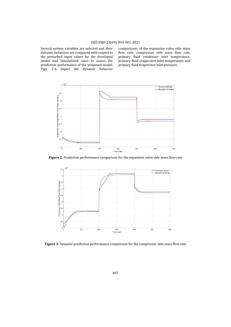
Several system variables are selected and their dynamic behaviors are compared with respect to the perturbed input values for the developed model and SimulationX cases to assess the prediction performance of the proposed model. Figs. 2-6 depict the dynamic behavior
comparisons of the expansion valve side mass flow rate, compressor side mass flow rate, primary fluid condenser inlet temperature, primary fluid evaporator inlet temperature and primary fluid evaporator inlet pressure.
Figure 2. Prediction performance comparison for the expansion valve side mass flow rate
Figure 3. Dynamic prediction performance comparison for the compressor side mass flow rate

DEÜ FMD 23(69), 893-901, 2021
898
Figure 4. Prediction performances for the primary fluid condenser inlet temperature
Figure 5. Predictions of the developed model and SimulationX model for the primary fluid evaporator inlet temperature

DEÜ FMD 23(69), 893-901, 2021
899
Figure 6. Dynamic prediction performance comparison for the primary fluid evaporator inlet pressure
As can be seen from the figures, the developed model predictions agree well with the SimulationX model output. A slight disagreement between the two model outputs are noticed for the first few seconds, however, they both converge to similar values eventually. The mentioned disagreements occur due to the utilization of different models and numerical
methods for the simulation of the vapor compression cycles. The largest prediction difference is observed as 2x10⁻⁴ kg/sec. for the mass flow rates and 1.4 K for the inlet temperatures. Figs. 7-8 show the prediction performance comparisons of the two models for the compressor work and cycle coefficient of performance.
Figure 7. Dynamic behavior of the compressor work for the developed and SimulationX models

DEÜ FMD 23(69), 893-901, 2021
900
Figure 8. Dynamic outputs of the cycle coeffient of performance for the two compared models
It is observed from Fig. 7 that both models predict similar compressor work values over the simulation time. However, slight differences are noticed for the coefficient of performance predictions of the two models. The coefficient of performance predictions of the two models converge to similar steady-state values, however, they display different behaviors at the transient region. These variances occur due to the use of different mathematical equations and correlations for the development of the cycle model. The largest observed coefficient of performance prediction difference between the two models is 0.22. Furthermore, the zig-zags at the coefficient of performance prediction of the developed model happen because of the instabilities in the evaporation correlation.
4. Discussion and Conclusion
This paper deals with the dynamic modeling of a vapor compression cycle. The evaporator and condenser are modeled by utilizing the finite difference method and the compressor and expansion valve are modeled with static relationships. R134a and water are used as the primary and secondary fluid of the cycle, respectively. The proposed model is developed in Java programming environment. Another vapor compression cycle model with the same design specifications is developed in the SimulationX software to verify the proposed model. The two models are perturbed with two different input variables, namely the expansion valve openness and compressor motor speed,
with varying values over constant intervals. The results showed that the transient outcomes of the two compared models agree well with each other. The largest observed prediction difference is 2x10⁻⁴ kg/sec. for the mass flow rates and 1.4 K for the inlet temperatures. Moreover, the two models are able to predict similar compressor work values over the simulation time.
References
[1] Goetzler, W., Shandross, R., Young, J., Petritchenko, O., Ringo, D., McClive, S. 2017. Energy Savings Potential and RD&D Opportunities for Commerical Building HVAC Systems, US Department of Energy, Massachussets, USA, 172s.
[2] MacArthur, J.W. 1984. Transient pump behaviour: a theoretical investigation. International Journal of Refrigeration, Cilt. 7, s. 123-132. DOI: 10.1016/0140-7007(84)90025-2.
[3] Chi, J. 1979. DEPAC- a computer model for design and performance analysis of central chillers. ASME Paper No 77-HT-11.
[4] Chi, J. 1976. Computer simulation of fossil-fuel-fired hydronic boilers. ASHRAE HVAC Equipment.
[5] Chi, J., Didion, D. 1982. A simulation model of the transient performance of a heat pump. International Journal of Refrigeration, Cilt. 5, s.176-184. DOI: 10.1016/0140-7007(82)90099-8
[6] Bonne, U., Patani, A., Jacobson, R., Muller, D. 1980. Electric-driven heat pump system: simulation and controls, ASHRAE Transactions LA-80-5 Los Angeles, California.
[7] Chen, Z.J., Lin, W. 1991. Dynamic simulation and optimal matching of a small-scale refrigeration system. International Journal of Refrigeration. Cilt. 5, s. 329-335. DOI: 10.1016/0140-7007(91)90028-F

DEÜ FMD 23(69), 893-901, 2021
901
[8] Fu, L., Ding, G., Zhang, C. 2003. Dynamic simulation of air-to-water dual-model heat pump with screw compressor. Applied Thermal Engineering. Cilt. 23, s. 1629-1645. DOI: 10.1016/S1359-4311(03)00109-1
[9] Rasmussen, B.P., Alleyne, A.G. 2006. Dynamic Modeling and Advanced Control of Air Conditioning and Refrigeration Systems. University of Illinois at Urbana-Chamapaign Air Conditioning and Refrigeration Center Technical Report TR-244.
[10] Rasmussen, B.P., Shenoy, B. 2012. Dynamic modeling for vapor compression systems-Part II: Simulation Tutorial. HVAC&R Research. Cilt. 18, s. 956-973. DOI: 10.1080/10789669.2011.582917
[11] Güngör K.E., Winterton, R.H.S. 1985. A general correlation for flow boiling in tubes and annuli. International Journal of Heat and Mass Transfer. Cilt. 29, s. 351-358. DOI: 10.1016/0017-9310(86)90205-X
[12] Travis, D.P., Baron, A.G., Rosenhow, W.M. 1971. Forced-convection condensation inside tubes. MIT Heat Transfer Laboratory, 74.
[13] Müller-Steinhagen, H., Heck, K. 1986. A Simple Friction Pressure Drop Correlation for Two-Phase Flow in Pipes. Chemical Engineering and Processing: Process Intensification. Cilt. 20, s. 297-308. DOI: 10.1016/0255-2701(86)80008-3
[14] ESI ITI SimulationX. 2020. SimulationX. www.simulationx.com. (Accessed: 25.11.2020)
[15] Bergman, T.L., Lavine, A.S., Incropera, F.P., DeWitt, D.P. 2018. Fundamentals of Heat and Mass Transfer 8th edition. Wiley Publishing, USA, 992s.
[16] Lemmon, E.W., Bell, I.H., Huber, M.L., McLinden, M.O. 2018. NIST Standard Reference Database 23: Reference Fluid Thermodynamic and Transport Properties-REFPROP, Version 10.0, National Institute of Standards and Technology, Standard reference Data Program, Gaithersburg, 2018. DOI: 10.18434/T4/1502528