Embed Size (px)
Citation preview

Development of 2 MVA Class Superconducting Fault Current
Limiting Transformer (SFCLT) with YBCO Coated
Conductors
M Kotari1, H Kojima
2, N Hayakawa
2, F Endo
2, H Okubo
1
1 Department of Electrical Engineering and Computer Science, Nagoya University,
Nagoya 464-8603, Japan 2 EcoTopia Science Institute, Nagoya University, Nagoya 464-8603, Japan
E-mail: [email protected]
Abstract. We have been developing Superconducting Fault Current Limiting Transformer
(SFCLT) with the functions of both superconducting transformer in normal operating condition
and superconducting fault current limiter in fault condition. As the Step-5 of SFCLT project, in
this paper, we designed and fabricated 2 MVA class HTS-SFCLT using YBCO coated
conductors with the ratings of 3-phase and 22 kV/6.6 kV. The developed HTS-SFCLT is
characterized by a hybrid structure of HTS coils using YBCO, YBCO/Cu and Bi2223 tapes for
the design flexibility as both of the superconducting transformer and the superconducting fault
current limiter. Fundamental tests of the HTS-SFCLT were carried out, and the design
parameters as a superconducting transformer were verified.
1. Introduction
High temperature superconducting (HTS) power apparatus, e.g. transmission cables, fault current
limiters, transformers, SMES, motors and generators, have been investigated and demonstrated [1]-[5].
The HTS power apparatus should be coordinated with a power system in order to improve the total
efficiency and stability in a future power system.
From the viewpoint of system coordination and functional diversification of superconducting
power apparatus, we have proposed and have been developing Superconducting Fault Current
Limiting Transformer, abbreviated to “SFCLT”, with the functions of both superconducting
transformer and superconducting fault current limiter from Step-1 to Step-4 [6]-[14]. As the Step-4 of
SFCLT project, we have designed, fabricated and tested HTS-SFCLT with the ratings of 3-phase, 100
kVA, 6600 V/210 V using YBCO coated conductors, and verified fundamental and excellent
performance of both HTS transformer and fault current limiter. As the Step-5 of SFCLT project, in
this paper, we designed and fabricated 2 MVA class HTS-SFCLT with YBCO coated conductors,
whose ratings are 3-phase and 22 kV/6.6 kV. The HTS-SFCLT is characterized by the combination of
different kinds of YBCO coated conductors in order to make the current limiting characteristics
flexible and controllable. No-load, short-circuit and partial-load tests were carried out to confirm the
design parameters and fundamental performance of the HTS-SFCLT as a superconducting transformer.

2. Concept of SFCLT
SFCLT proposed is characterized by the following concepts:
(1) SFCLT works as a HTS transformer in the normal condition, and also as a HTS fault current
limiter in the fault condition.
(2) Quench-induced impedance of SFCLT is positively utilized as a fault current limiter in the fault
condition.
(3) Fault current limiting function of SFCLT improves the transient stability of power system in the
fault condition.
(4) Limiting impedance of SFCLT is activated in the fault condition, and leakage impedance of a
transformer can be reduced, compared with that of conventional transformers.
(5) Reduced leakage impedance of SFCLT enhances the transmission capacity and static stability
of power system in the normal condition.
(6) After fault current limitation, SFCLT recovers into superconducting state after the fault
clearance.
The concepts (1)~(3) are fundamental functions of SFCLT, and (4)~(6) can be regarded as novel
functions to be expected for SFCLT in a power system. Especially, as for the recovery characteristics
in (6), we have verified that SFCLT could recover into superconducting state by itself immediately
after the fault clearance, i.e. self-recovery performance [9]-[11], [13]. Figure 1 shows an example of
the current limitation and recovery characteristics in Step-4 using 2G materials [13]. Against the
prospective current Ipro=980Apeak, the fault current was limited to 516 Apeak (52.6% of Ipro) at first peak
and 330 Apeak (33.7% of Ipro) at the 5th cycle, respectively, after the fault. In this case, the load current
ILV2 after the fault clearance was equal to ILV1 before the fault, which means that SFCLT exhibited the
self-recovery performance. Figure 2 shows the self-recovery characteristics of SFCLT in Step-4 as
parameters of ILV1 and Ipro normalized by the critical current IC of HTS tapes. A criterion of the self-
recovery was quantified by a dotted curve for different load and fault conditions, which can be
reflected to the design and operation of SFCLT.
Figure 1. Current waveform of recovery test of HTS-SFCLT (Step-4)
6
5
4
3
2
1
0
I PR
O / I
C
0.60.50.40.30.20.10.0
ILV1 / IC
Figure 2. Recovery characteristics of HTS-SFCLT (Step-4)
-1000
-500
0
500
1000
Low
-voltage s
ide c
urr
ent: I
LV [A
]
0.200.150.100.050.00-0.05
Time [s]
ILV2ILV1
Ipro
Fault clearanceFault
recovery case
non-recovery case

3. Design and fabrication of HTS-SFCLT (Step-5)
3.1. Transformer design
The specifications and construction of HTS-SFCLT in the Step-5 are shown in Table 1 and Figure 3.
We designed 3-phase HTS-SFCLT with the rating of 2 MVA, 22 kV/6.6 kV. As a single phase of the
HTS-SFCLT, we fabricated 0.67 MVA, 12.7 kV/3.81 kV (Y-Y). HTS coils were arranged in both core
legs (A-leg, B-leg) and immersed in liquid nitrogen at 77 K together with the iron core. Low-voltage
coils (A1~A6, B1~B6; total 12 coils connected in series) were composed of two types of YBCO tapes,
and high-voltage coils (A7~A10, B7~B10; total 8 coils connected in series) were composed of Bi2223
tapes. The specifications of each HTS tape are summarized in Table 2.
3.2. Fault current limiter design
Low-voltage coils of the HTS-SFCLT (Step-5) were divided into limiting coil (Tr/FCL coil) and non-
limiting coil (Tr coil), as was the case with the Step-4 [12], [13]. In the Step-5, A1~A3 and B1~B3 are
Tr/FCL coils using LV(I) YBCO tape in Table 2, and A4~A6 and B4~B6 are Tr coils using LV(II)
YBCO/Cu tape in Table 2. Such a hybrid structure of HTS coils brings about the higher flexibility for
both transformer and current limiter design by the variation of the ratio between Tr/FCL coil and Tr
coil.
Table 1. Specifications of
HTS-SFCLT (Step-5) Table 2. Specifications of 2G HTS tape (Step-5)
1)0.3V/cm 2)1.0V/cm
LV(I) LV(II) HV
HTS layer YBCO YBCO Bi2223
Substrate Hastelloy Hastelloy -
Buffer layer IBAD MgO IBAD MgO -
Stabilizer Ag Cu Ag
Width [mm] 12 12 2.6
Thickness [mm] 0.105 0.095 0.230
IC [A] @77K 2151)
2402)
732)
Length [m] 124 147 1154
Phase 3
Frequency 60Hz
Capacity 2MVA
Rated voltage 22kV/6.6kV
Rated current 52.5A/175A
Turn ratio 1334/396
Leakage impedance 6.1%
Magnetic flux density 1.7T
HV (Tr coil)
LV(Ⅰ)
(Tr/FCL coil)
LV(Ⅱ)
(Tr coil)
Figure 3. Construction of HTS-SFCLT (Step-5)
(a) Total structure (b) Cross-section and coil arrangement
B-leg coils A-leg coils
A1~A3 A4~A6
A7~A10 Iron core
FRP
cylinder
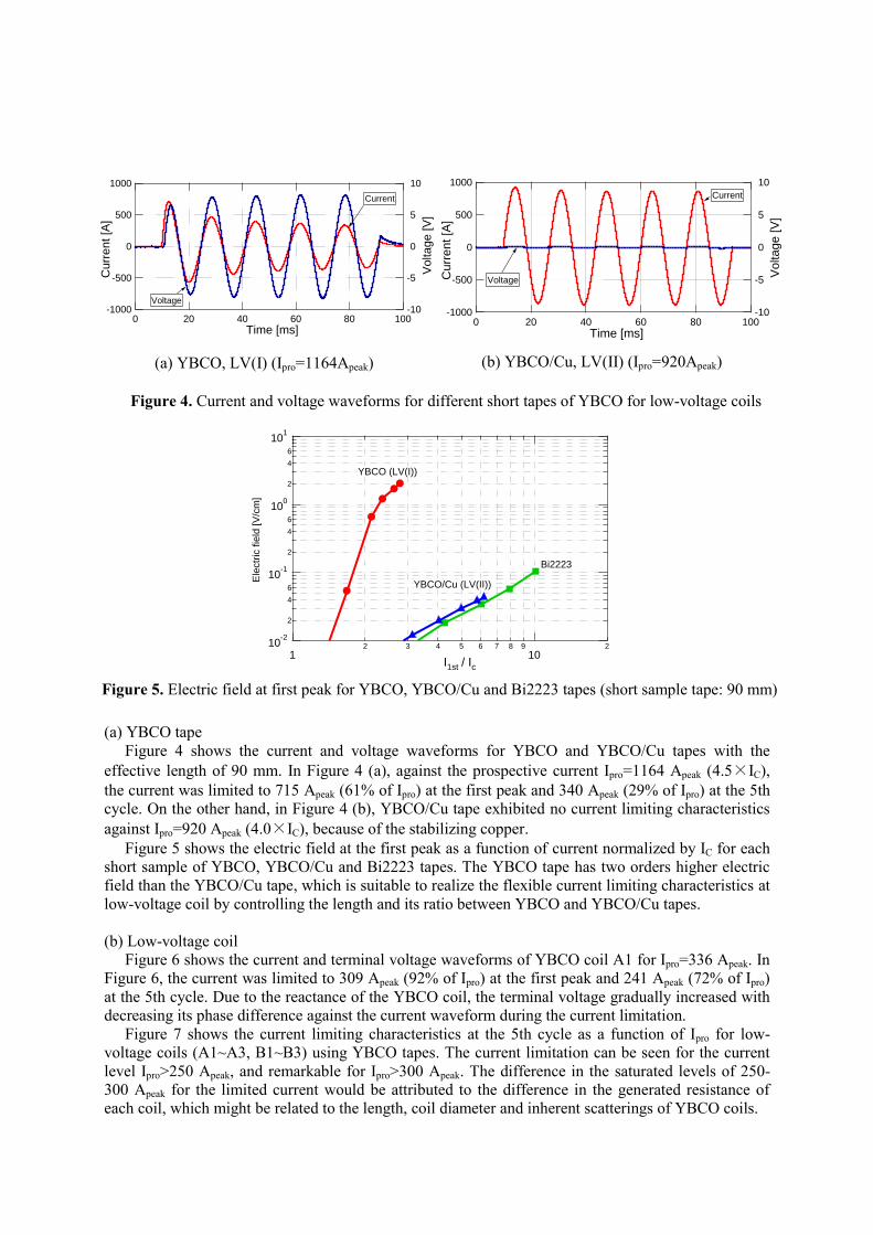
(a) YBCO tape
Figure 4 shows the current and voltage waveforms for YBCO and YBCO/Cu tapes with the
effective length of 90 mm. In Figure 4 (a), against the prospective current Ipro=1164 Apeak (4.5×IC),
the current was limited to 715 Apeak (61% of Ipro) at the first peak and 340 Apeak (29% of Ipro) at the 5th
cycle. On the other hand, in Figure 4 (b), YBCO/Cu tape exhibited no current limiting characteristics
against Ipro=920 Apeak (4.0×IC), because of the stabilizing copper.
Figure 5 shows the electric field at the first peak as a function of current normalized by IC for each
short sample of YBCO, YBCO/Cu and Bi2223 tapes. The YBCO tape has two orders higher electric
field than the YBCO/Cu tape, which is suitable to realize the flexible current limiting characteristics at
low-voltage coil by controlling the length and its ratio between YBCO and YBCO/Cu tapes.
(b) Low-voltage coil
Figure 6 shows the current and terminal voltage waveforms of YBCO coil A1 for Ipro=336 Apeak. In
Figure 6, the current was limited to 309 Apeak (92% of Ipro) at the first peak and 241 Apeak (72% of Ipro)
at the 5th cycle. Due to the reactance of the YBCO coil, the terminal voltage gradually increased with
decreasing its phase difference against the current waveform during the current limitation.
Figure 7 shows the current limiting characteristics at the 5th cycle as a function of Ipro for low-
voltage coils (A1~A3, B1~B3) using YBCO tapes. The current limitation can be seen for the current
level Ipro>250 Apeak, and remarkable for Ipro>300 Apeak. The difference in the saturated levels of 250-
300 Apeak for the limited current would be attributed to the difference in the generated resistance of
each coil, which might be related to the length, coil diameter and inherent scatterings of YBCO coils.
10-2
2
4
6
10-1
2
4
6
100
2
4
6
101
Ele
ctr
ic f
ield
[V
/cm
]
12 3 4 5 6 7 8 9
102
I1st / Ic
YBCO (LV(I))
YBCO/Cu (LV(II))
Bi2223
Figure 5. Electric field at first peak for YBCO, YBCO/Cu and Bi2223 tapes (short sample tape: 90 mm)
Figure 4. Current and voltage waveforms for different short tapes of YBCO for low-voltage coils
(a) YBCO, LV(I) (Ipro=1164Apeak) (b) YBCO/Cu, LV(II) (Ipro=920Apeak)
-1000
-500
0
500
1000
Curr
ent [A
]
100806040200
Time [ms]
-10
-5
0
5
10
Voltage [V
]
Current
Voltage
-1000
-500
0
500
1000
Curr
ent [A
]
100806040200
Time [ms]
-10
-5
0
5
10
Voltage [V
]
Current
Voltage

4. No-load, short-circuit and partial-load tests of HTS-SFCLT (Step-5)
The assembled HTS-SFCLT (Step-5) was immersed in liquid nitrogen at atmospheric pressure. No-
load and short-circuit tests were carried out in order to confirm the design parameters of the HTS-
SFCLT as a superconducting transformer. In both tests, the turn ratio between high-voltage and low –
voltage coils was confirmed to agree well with the design value. The results of no-load test are shown
in Figure 8; (a) exciting current and (b) no-load loss. At the rated voltage of 3.81 kVrms, the exciting
current was 0.55 Apeak, whereas the no-load loss was 411 W. The leakage impedance obtained in the
short-circuit test was 6.0%, which is also in good arrangement with the design value of 6.1%.
The partial-load test was carried out by connecting a resistive load of 1 between the low-voltage
terminals. Figure 9 shows the current and voltage waveforms at the partial-load test, where the current
in the low-voltage coil was 92 Apeak, i.e. 37% of the rated current. The relationship in current and
voltage waveforms between high-voltage and low-voltage coils was verified to be appropriate as a
superconducting transformer.
-400
-200
0
200
400
Cu
rre
nt
[A]
100806040200
Time [ms]
-80
-40
0
40
80
Term
ina
l volta
ge
[V
]
Voltage
Current
Figure 6. Current and terminal voltage waveforms at current limitation (Coil A1, Ipro=336Apeak)
Figure 7. Current limiting characteristics at 5th cycle for low-voltage coils (A1~A3, B1~B3)
400
300
200
100
0
Lim
ited
curr
ent
[Ap
ea
k]
4003002001000
Prospective current : Ipro [Apeak]
A1
B1
A2
B2
A3
B3
Ipro

5. Key technologies for SFCLT development
From the viewpoints of transformer, fault current limiter, material and power system, key technologies
for SFCLT development can be listed as follows:
・As for the transformer function, electrical insulation techniques and test procedure should be
established. AC loss reduction of HTS tapes and the optimization of leakage impedance of
SFCLT are expected.
・As for the fault current limiter function, electrical insulation techniques and test procedure are
also inevitable, especially under quench-induced thermal/electrical combined stress. The
flexibility and controllability of current limitation and self-recovery performance should be
enhanced.
・From the material viewpoint, the performance of HTS tapes should be balanced in large current
capacity, low ac loss, high electric field in overcurrent condition, etc, under the operating and
cooling environment at the optimum temperature and pressure.
・From the power system viewpoint, the static and transient stability should be coordinated and
optimized.
500
400
300
200
100
0
No
-loa
d lo
ss [W
]
43210
LV voltage : VLV [kVrms]
0.6
0.5
0.4
0.3
0.2
0.1
0.0
Excitin
g c
urr
ent [A
pe
ak]
43210
LV voltage : VLV [kVrms]
Figure 8. No-load test results of HTS-SFCLT (Step-5)
(a) Exciting current (b) No-load loss
Figure 9. Current and voltage waveforms at partial-load test (ILV = 92 Apeak)
-100
-50
0
50
100
Cu
rre
nt
[A]
100806040200
Time [ms]
-1000
-500
0
500
1000
Vo
lta
ge
[V
]
VLVVHV
IHVILV
Rated
voltage
Rated
voltage

6. Conclusions
As the Step-5 of SFCLT project, we developed 2 MVA class HTS-SFCLT with YBCO coated
conductors, and carried out the no-load test, short-circuit test and partial-load test as a superconducting
transformer. The main results are summarized as follows:
・The design ratings of the HTS-SFCLT (Step-5) are 3-phase, 2 MVA, 22 kV/6.6 kV. A single
phase of HTS-SFCLT was fabricated.
・Low-voltage coils were composed of YBCO tape for limiting coil (Tr/FCL coil) and YBCO/Cu
tape for non-limiting coil (Tr coil). High-voltage coils were composed of Bi2223 tape. Electric
field and current limiting characteristics of each tape and coil were verified.
・No-load, short-circuit and partial-load test results verified that the HTS-SFCLT would exhibit
the fundamental performance with the design parameters as a superconducting transformer.
The developed HTS-SFCLT (Step-5) will be tested by current limiting test and recovery test after the
current limitation.
Acknowledgement
This work was supported by the Grant-in-Aid for Scientific Research (S) of the Ministry of Education,
Culture, Sports, Science and Technology, Japan.
References
[1] M.J.Gouge et al., 2009 IEEE Trans. on Appl. Supercond. 19 1744-1747
[2] H.Yumura et al., 2009 IEEE Trans. on Appl. Supercond. 19 1698-1701
[3] M.Noe et al., 2007 Supercond. Sci. Technol. 20 R15
[4] H.-W.Neumueller et al., 2009 IEEE Trans. on Appl. Supercond. 19 1950-1955
[5] K.Shikimachi et al., 2009 IEEE Trans. on Appl. Supercond. 19 2012-2018
[6] N.Hayakawa et al., 2000 Cryogenics 40 325-331
[7] N.Hayakawa et al., 2001 IEEE Trans. on Appl. Supercond. 11 1936-1939
[8] H.Kagawa et al., 2002 Physica C 372-376 1706-1710
[9] C.Kurupakorn et al., 2004 IEEE Trans. on Appl. Supercond. 14 900-903
[10] C.Kurupakorn et al., 2005 IEEE Trans. on Appl. Supercond. 15 1859-1862
[11] C.Kurupakorn et al., 2006 J.Physics: Conference Series, 43 950-953
[12] H.Okubo et al., 2007 IEEE Trans. on Appl. Supercond. 17 1768-1771
[13] H.Kojima et al., 2008 J.Physics: Conference Series, 97 012154
[14] K.Omura et al., 2009 IEEE Trans. on Appl. Supercond. 19 1880-1883