Embed Size (px)
Citation preview
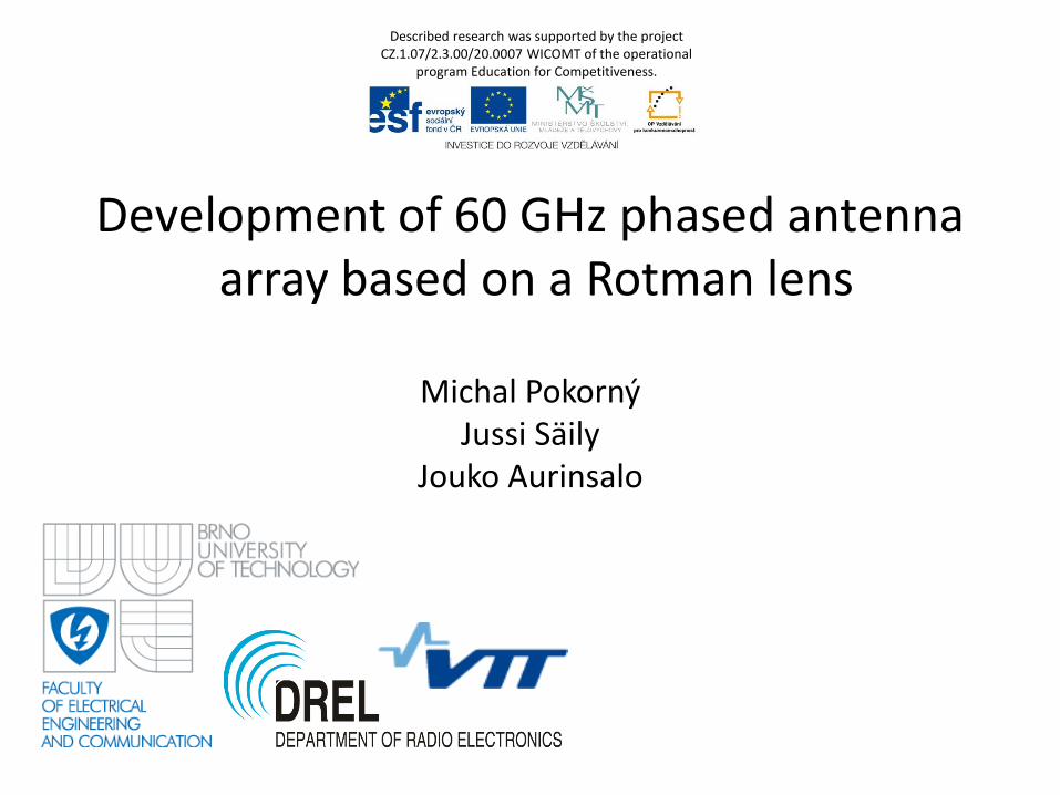
Development of 60 GHz phased antenna array based on a Rotman lens
Michal Pokorný Jussi Säily
Jouko Aurinsalo
Described research was supported by the project CZ.1.07/2.3.00/20.0007 WICOMT of the operational
program Education for Competitiveness.
• Rotman Lens Origin
• Interesting Properties of Rotman Lens
• Example RL Design at 50-70 GHz
• Difficulties in Practical Implementation
Outline
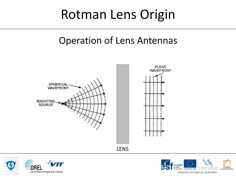
Operation of Lens Antennas
Rotman Lens Origin
7th March 2013
LENS
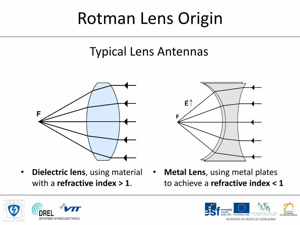
Typical Lens Antennas
• Dielectric lens, using material with a refractive index > 1.
• Metal Lens, using metal plates to achieve a refractive index < 1
Rotman Lens Origin
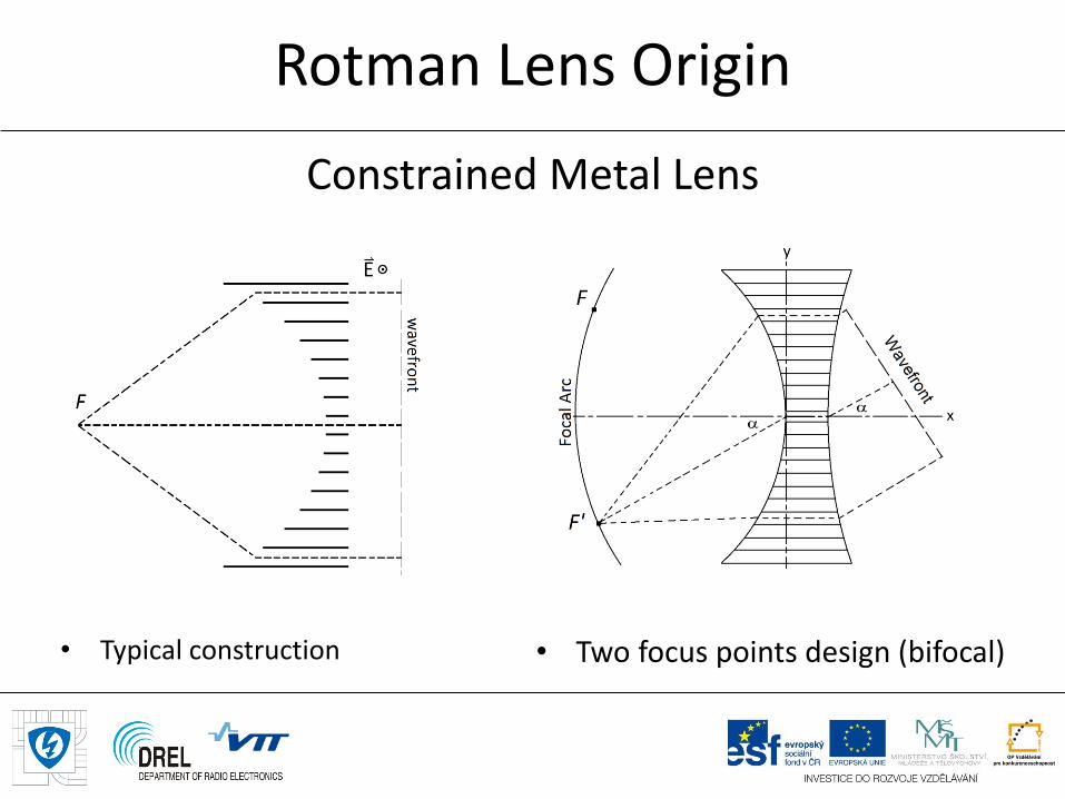
Constrained Metal Lens
• Typical construction • Two focus points design (bifocal)
Rotman Lens Origin
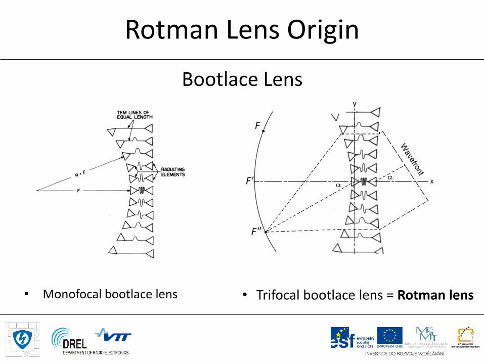
• Monofocal bootlace lens • Trifocal bootlace lens = Rotman lens
Rotman Lens Origin
Bootlace Lens
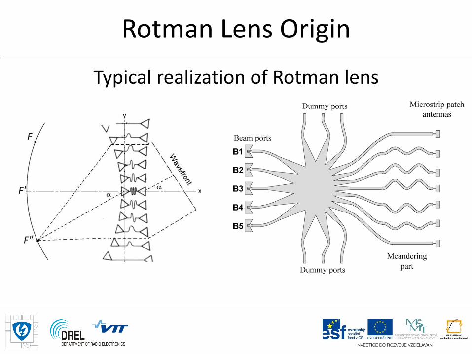
Rotman Lens Origin
Typical realization of Rotman lens
• Multiple beams without the need for phase shifters
• True time-delay device = broadband operation
• Wide scanning angle, typically ± 30°
• All beams can be used simultaneously or can be switched at high rate → pattern diversity (MIMO)
• Beam ports could be combined to create summative or differential diagrams.
Interesting Properties of Rotman Lens
Printed RL on LCP substrate; r = 2.9, th = 100 m
Important input design parameters:
• Central frequency 60 GHz
• Beam scanning angle = ± 30°
• Antenna element spacing 0/2
• Length of the parallel plate region 4r
• 4 beam ports
• 8 array ports
• 8 dummy ports
Example RL Design at 50-70 GHz
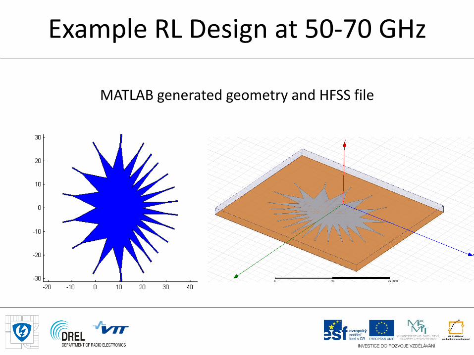
MATLAB generated geometry and HFSS file
Example RL Design at 50-70 GHz
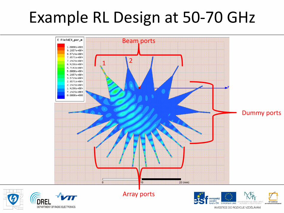
Example RL Design at 50-70 GHz Beam ports
Array ports
Dummy ports
1 2
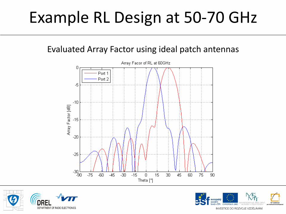
Example RL Design at 50-70 GHz
Evaluated Array Factor using ideal patch antennas
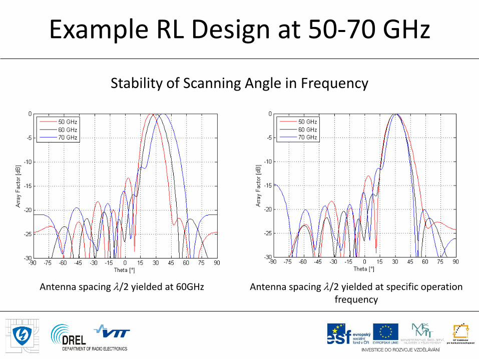
Example RL Design at 50-70 GHz
Antenna spacing /2 yielded at 60GHz
Antenna spacing /2 yielded at specific operation frequency
Stability of Scanning Angle in Frequency
Example RL Design at 50-70 GHz
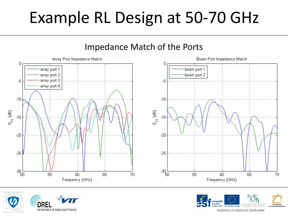
Impedance Match of the Ports
Example RL Design at 50-70 GHz
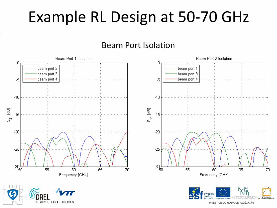
Beam Port Isolation
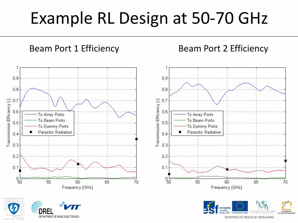
Example RL Design at 50-70 GHz
Beam Port 1 Efficiency Beam Port 2 Efficiency
Difficulties in Practical Implementation
Lens feeding • SP4T, non-reflective switch (not available on the market)
• Switching network using non-reflective SPST switches (additional losses)
• Extra radio at each beam port (interesting for MIMO)
Losses due to • Substrate tangent delta (not included in this presentation)
• Illumination of the dummy ports
• Parasitic radiation (could be reduced in case of SIW realization)
Dummy port matched load • Absorbing material
• Small package resistors
• Printed resistors

Described research was supported by the project CZ.1.07/2.3.00/20.0007 WICOMT of the operational program Education for Competitiveness.

Thank you for your attention