Embed Size (px)
Citation preview

DEVELOPMENT OF A COMPREHENSIVE
BATTERY ENERGY STORAGE SYSTEM
MODEL FOR GRID ANALYSIS
1
MODEL FOR GRID ANALYSIS
APPLICATIONS
By: Eng. Mostafa Kamal Salem
Under Supervision Of:Prof. Dr.-Eng. Peter ZachariasProf. Dr.-Eng. Adel KhalilProf. Dr.-Eng. Amr AdlyDr.-Eng. Stefan Kempen
19.03.2013

Acknowledgment
Battery E
nergy Storage S
ystem B
ES
S
I would like to thank all the people who helped me in achieving this thesis. Very special thanks to my supervisors: Prof.
Dr. Adel Khalil, Prof. Dr. Peter Zacharias, and Prof. Dr. Amr Adly for their supervision and support. I would like to
thank the examining committee for their time. I would like to express my appreciation to AEG Power Solutions for giving
me the opportunity to work on my master thesis in the company with its quality service provisions. Special thanks to Dr.-
Ing Kempen, M.Sc.-Ing Ammar Salman, and Mr. John Kuhne for their support and guidance. Also, I would like to thank
the German Academic Exchange Service (DAAD) for supporting REMENA master program and for providing me the
financial and moral support. Special thanks to Ms. Anke Stahl and Ms. Janique Bikomo for supporting and care. I would
like to express my appreciation to the University of Kassel and Cairo University for hosting me in the master course.
2
Battery E
nergy Storage S
ystem B
ES
S
like to express my appreciation to the University of Kassel and Cairo University for hosting me in the master course.
Special thanks to Prof. Adel Khalil, Prof. Sayed Kaseb, Prof. Dirk Dahlhaus, and Ms. Anke Aref for the support and
guidance during the whole program.
Outlines
1.Introduction
2.Methodology & Procedure
3. Review of Literature � Battery Types� Battery Models
4. Model in Power Factory
5. Simulations & Results� BESS TEST
Battery E
nergy Storage S
ystem B
ES
S
2 Min.
1 Min.
2 Min.
4 Min.
8 Min.
3
� BESS TEST� Public Grid with and without BESS� BESS with AEG Grid� BESS with PV
6. Conclusion
7. Future Recommendations
8.Summary
9. References
Battery E
nergy Storage S
ystem B
ES
S2 Min.
2 Min.
1 Min.

Motivation:
The major challenge now days is to store the excess energy from the renewable energy that
generated when demand is low, and reuse this energy in later time or in the high demand
times.
1. Introduction
Battery E
nergy Storage S
ystem B
ES
S
4
Battery E
nergy Storage S
ystem B
ES
S
Source: www.renewableenergyworld.com

Aim of work:
To Build comprehensive model of the battery energy storage system that simulates the real
reactions that happens inside the battery, and to be able to analyze different grid scenarios
using Power Factory DIgSILENT.
1. Introduction
Battery E
nergy Storage S
ystem B
ES
S
5
Battery E
nergy Storage S
ystem B
ES
S
Source: www.newavenergy.com
1. Introduction
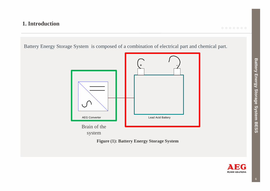
Battery Energy Storage System is composed of a combination of electrical part and chemical part.
Battery E
nergy Storage S
ystem B
ES
S
+ -
6
Battery E
nergy Storage S
ystem B
ES
S
AEG Converter Lead Acid Battery
Brain of the system
Figure (1): Battery Energy Storage System

1. Introduction
BESS Advantages:
1. Active power output/input (support grid frequency).
2. Reactive power output/input (voltage control).
3. Pure phase shift operation is possible.
4. Charge and discharge at any desired cosф.
Battery E
nergy Storage S
ystem B
ES
S
7
Figure (2): PQ Characteristics for BESS [5]
Battery E
nergy Storage S
ystem B
ES
S
2. Methodology & Procedure
IdentifyThe
Problem
Search for Solutions & Model
Run The Model
Battery E
nergy Storage S
ystem B
ES
S
8
Problem & Model Model
Battery E
nergy Storage S
ystem B
ES
S
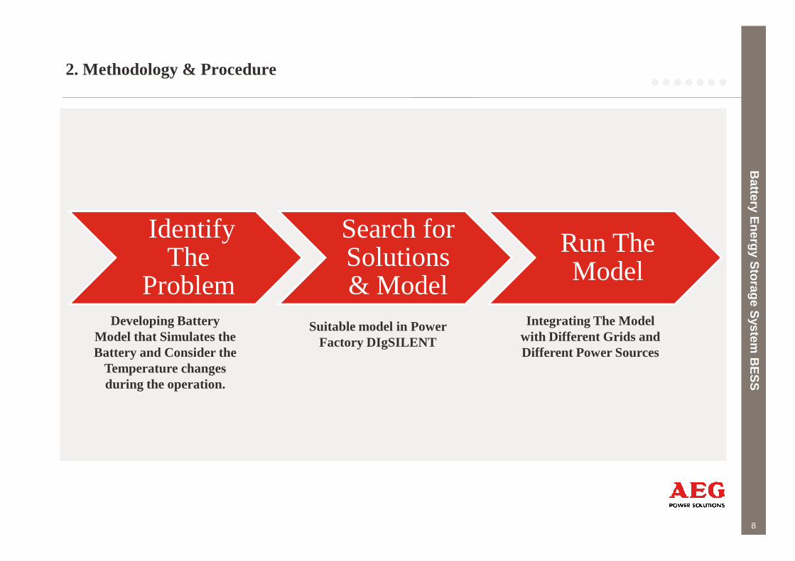
Developing Battery Model that Simulates the Battery and Consider the
Temperature changes during the operation.
Suitable model in Power Factory DIgSILENT
Integrating The Model with Different Grids and Different Power Sources
2. Methodology & Procedure
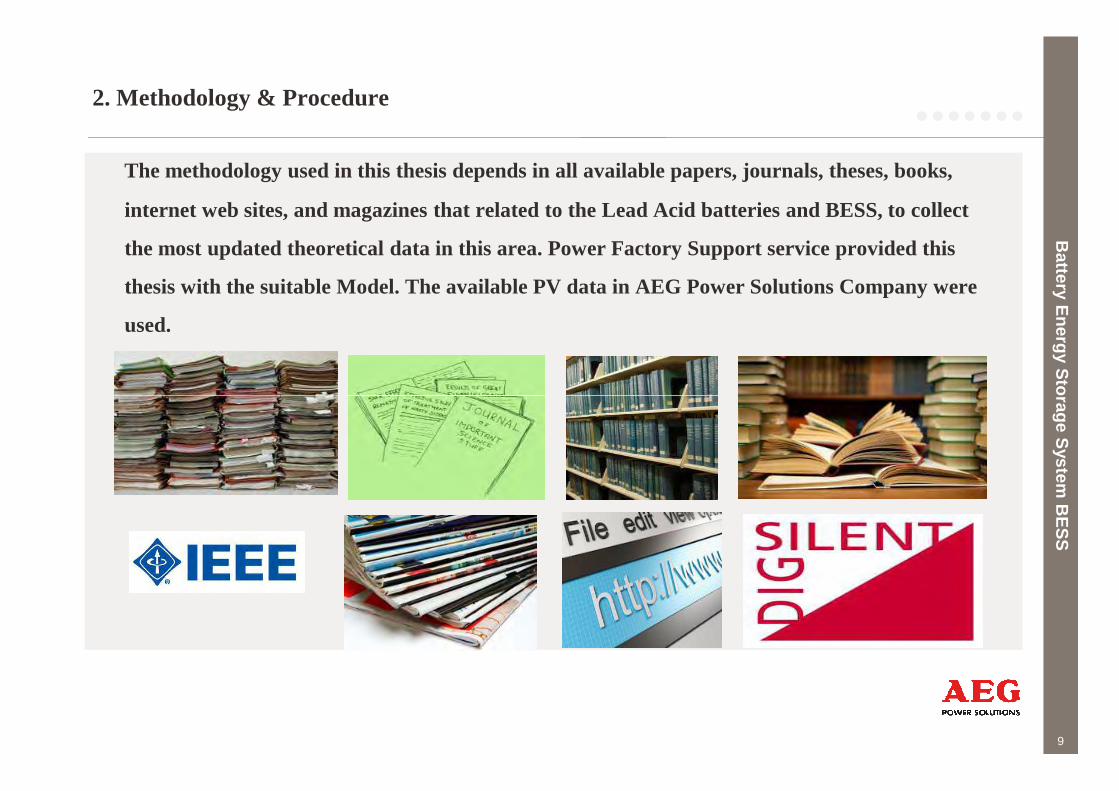
The methodology used in this thesis depends in all available papers, journals, theses, books,
internet web sites, and magazines that related to the Lead Acid batteries and BESS, to collect
the most updated theoretical data in this area. Power Factory Support service provided this
thesis with the suitable Model. The available PV data in AEG Power Solutions Company were
used.
Battery E
nergy Storage S
ystem B
ES
S
9
Battery E
nergy Storage S
ystem B
ES
S
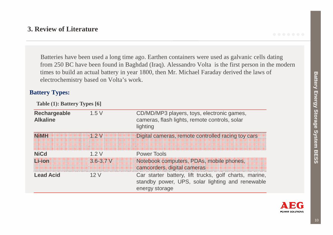
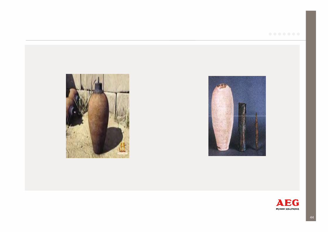
Batteries have been used a long time ago. Earthen containers were used as galvanic cells dating from 250 BC have been found in Baghdad (Iraq). Alessandro Volta is the first person in the modern times to build an actual battery in year 1800, then Mr. Michael Faraday derived the laws of electrochemistry based on Volta’s work.
Battery Types:
Battery E
nergy Storage S
ystem B
ES
S
RechargeableAlkaline
1.5 V CD/MD/MP3 players, toys, electronic games,cameras, flash lights, remote controls, solar
Table (1): Battery Types [6]
3. Review of Literature
10
Battery E
nergy Storage S
ystem B
ES
S
Alkaline cameras, flash lights, remote controls, solarlighting
NiMH 1.2 V Digital cameras, remote controlled racing toy cars
NiCd 1.2 V Power ToolsLi-ion 3.6-3.7 V Notebook computers, PDAs, mobile phones,
camcorders, digital camerasLead Acid 12 V Car starter battery, lift trucks, golf charts, marine,
standby power, UPS, solar lighting and renewableenergy storage
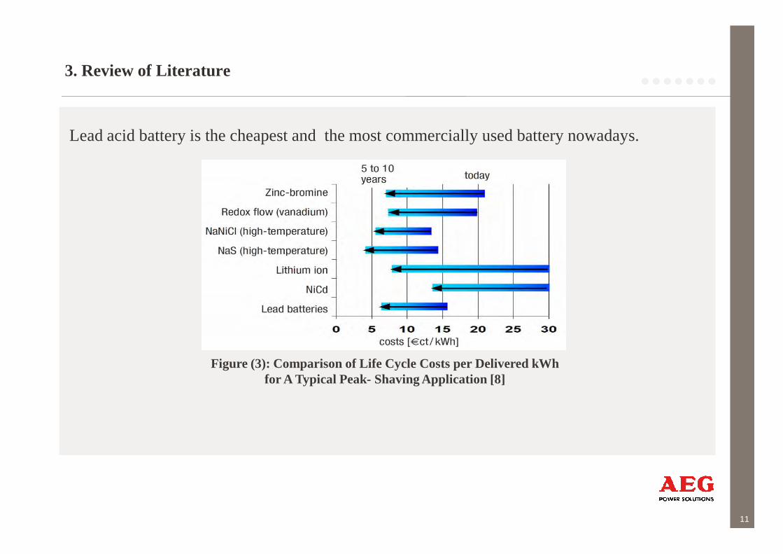
Lead acid battery is the cheapest and the most commercially used battery nowadays.
3. Review of Literature
11
Figure (3): Comparison of Life Cycle Costs per Delivered kWh for A Typical Peak- Shaving Application [8]

Battery E
nergy Storage S
ystem B
ES
S
Battery Models:
1. Simple Model.
2. Advanced Model (Ceraolo Model).
3. Review of Literature
12
Battery E
nergy Storage S
ystem B
ES
SFigure (4): Structure of the BESS In Power Factory [11]
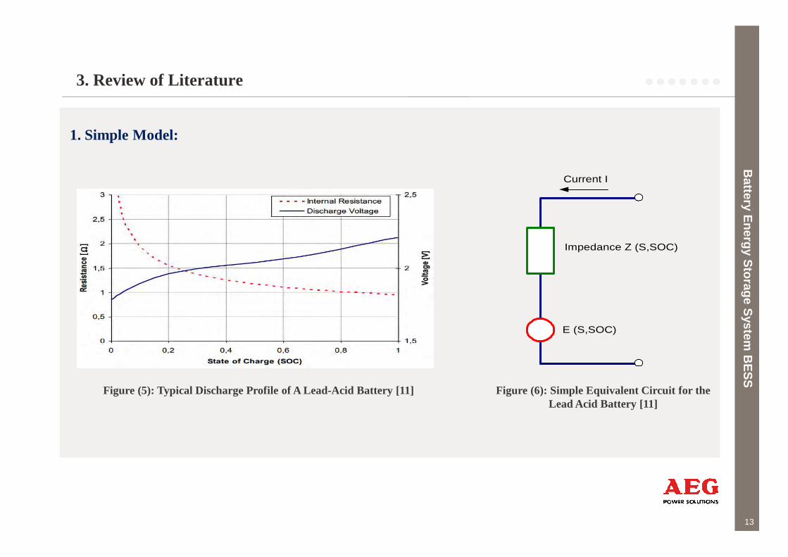
1. Simple Model:
Battery E
nergy Storage S
ystem B
ES
S
Impedance Z (S,SOC)
Current I
3. Review of Literature
13
Battery E
nergy Storage S
ystem B
ES
S
E (S,SOC)
Figure (6): Simple Equivalent Circuit for the Lead Acid Battery [11]
Figure (5): Typical Discharge Profile of A Lead-Acid Battery [11]
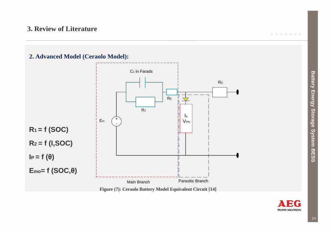
2. Advanced Model (Ceraolo Model):
Battery E
nergy Storage S
ystem B
ES
S
+
C1 in Farads
R1
R2
Ip,
R0
3. Review of Literature
14
Battery E
nergy Storage S
ystem B
ES
S
+-
Em
Main Branch Parasitic Branch
Ip,
VPN
Figure (7): Ceraolo Battery Model Equivalent Circuit [14]
R1 = f (SOC)
R2 = f (I,SOC)
IP = f (θ)
Emo= f (SOC,θ)

3. Review of Literature
2. Advanced Model (Ceraolo Model) during the operation:
Battery E
nergy Storage S
ystem B
ES
S
15
Battery E
nergy Storage S
ystem B
ES
S
Figure (9): Implemented Model [14]

4. Model in Power Factory
Battery E
nergy Storage S
ystem B
ES
S
(Battery Capacity)
θ (t) = θinit +
C = f (I,θ)
16
Battery E
nergy Storage S
ystem B
ES
S
Depth of Discharge
State of ChargeDepth of Discharge
Depth of Discharge =
f (Open Circuit Voltage (Ue))
Depth of Discharge = Q/ C
Ucell = Ue+UrsState of Charge
C = f (I,θ)
Battery Outputs
4. Models in Power Factory
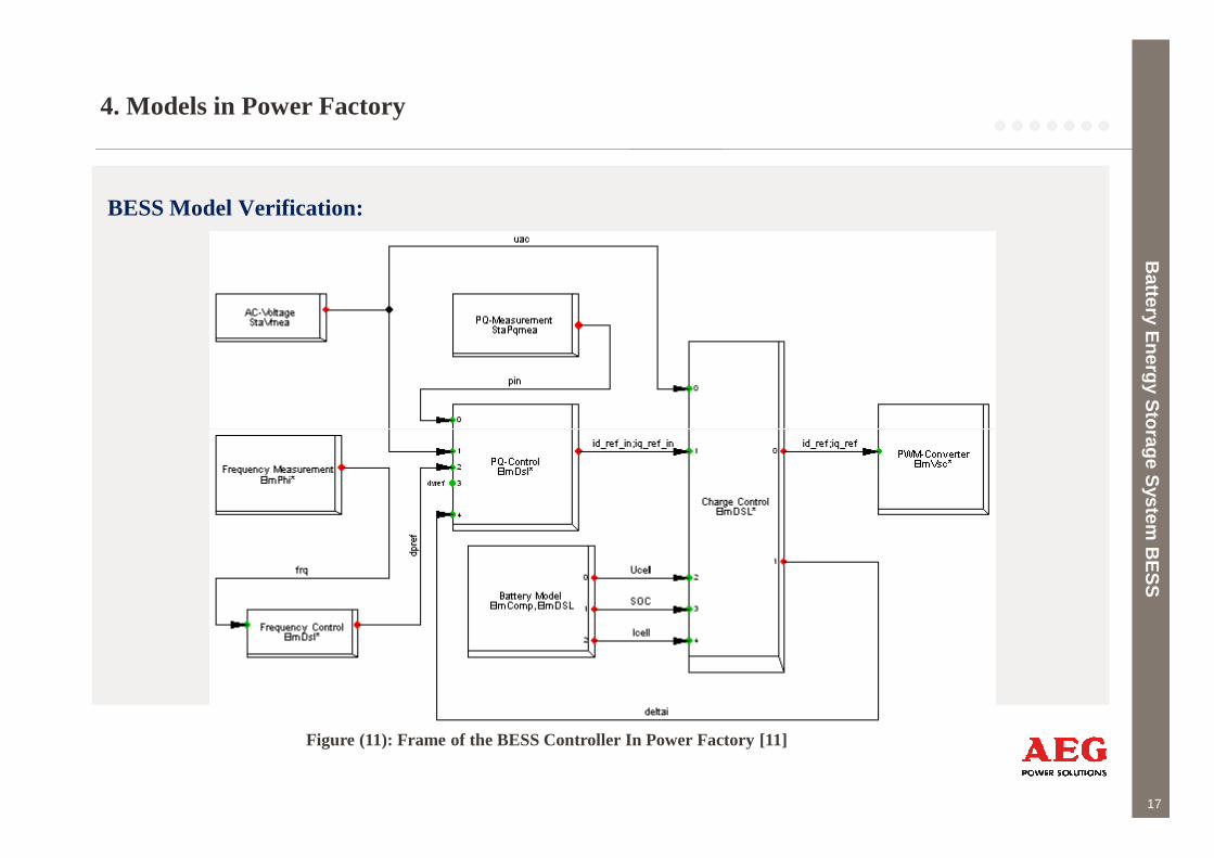
BESS Model Verification:
Battery E
nergy Storage S
ystem B
ES
S
17
Battery E
nergy Storage S
ystem B
ES
S
Figure (11): Frame of the BESS Controller In Power Factory [11]

Outlines
1.Introduction
2.Methodology & Procedure
3. Review of Literature � Battery Types� Battery Models
4. Models in Power Factory
5. Simulations & Results� BESS TEST
Battery E
nergy Storage S
ystem B
ES
S
18
� BESS TEST� Public Grid with and without BESS� BESS with AEG Grid� BESS with PV
6. Conclusion
7. Future Recommendations
8.Summary
9. References
Battery E
nergy Storage S
ystem B
ES
S
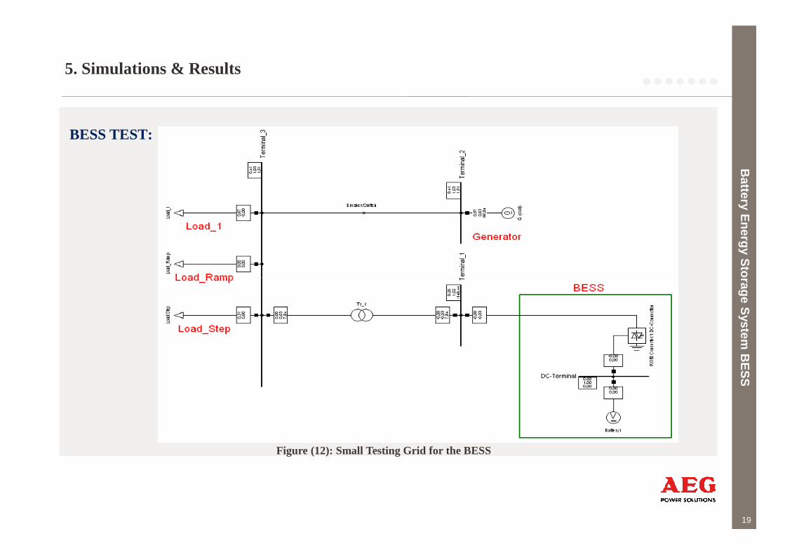
5. Simulations & Results
BESS TEST:
Battery E
nergy Storage S
ystem B
ES
S
19
Battery E
nergy Storage S
ystem B
ES
S
Figure (12): Small Testing Grid for the BESS
5. Simulations & Results
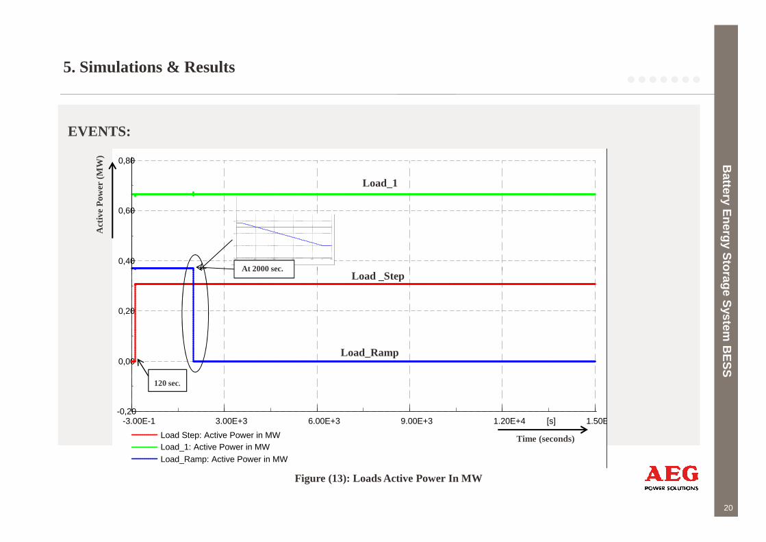
EVENTS:
Battery E
nergy Storage S
ystem B
ES
S
0,80
0,60
0,40
Act
ive
Pow
er (
MW
)
Load _Step
Load_1
2000,02000,02000,02000,02000,02000,0 [s]
0,40
0,20
0,00
-0,20
Load Step: Active Power in MW
Load_1: Active Power in MWLoad_Ramp: Active Power in MW
At 2000 sec.
20
Battery E
nergy Storage S
ystem B
ES
S
1.50E+41.20E+49.00E+36.00E+33.00E+3-3.00E-1 [s]
0,20
0,00
-0,20
Load Step: Active Power in MWLoad_1: Active Power in MWLoad_Ramp: Active Power in MW
Time (seconds)
Load_Ramp
Load _Step
120 sec.
At 2000 sec.
Figure (13): Loads Active Power In MW

5. Simulations & Results
Results:
Battery E
nergy Storage S
ystem B
ES
S
1,60
1,40
1,20
1,00
DIg
SIL
EN
T
120,39118,45
1,30
1,20
1,10
1,00
G (coal): Active Power in MW
Transient due to the event
1,02
0,98
0,94
0,90
DIg
SIL
EN
T
1,00
Act
ive
Pow
er (
MW
)
SOC
Uni
t le
ss
120 sec.
21
Battery E
nergy Storage S
ystem B
ES
S
1.50E+41.20E+49.00E+36.00E+33.00E+3-3.00E-1 [s]
0,80
0,60
G (coal): Active Power in MW
Figure (15): Synchronous Generator Active Power In MW
1.50E+41.20E+49.00E+36.00E+33.00E+3-3.00E-1 [s]
0,86
0,82
Charging Control: SOC
Figure (14): The Battery State Of ChargeTime (seconds)Time (seconds)
At 2000 sec.
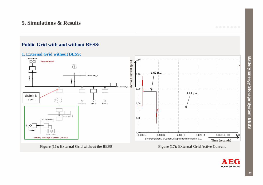
5. Simulations & Results
Public Grid with and without BESS:
1. External Grid without BESS: Battery E
nergy Storage S
ystem B
ES
S
2,10
1,90
1,70
DIg
SIL
EN
T
Act
ive
Cur
rent
(p.u
.)External Grid
1.62 p.u.
1.41 p.u.
22
Battery E
nergy Storage S
ystem B
ES
S
Switch isopen
Figure (16): External Grid without the BESS
1.70E+41.36E+41.02E+46.80E+33.40E+3-3.00E-1 [s]
1,50
1,30
1,10
Breaker/Switch(1): Current, Magnitude/Terminal i in p.u.
Figure (17): External Grid Active Current
Time (seconds)
1.41 p.u.
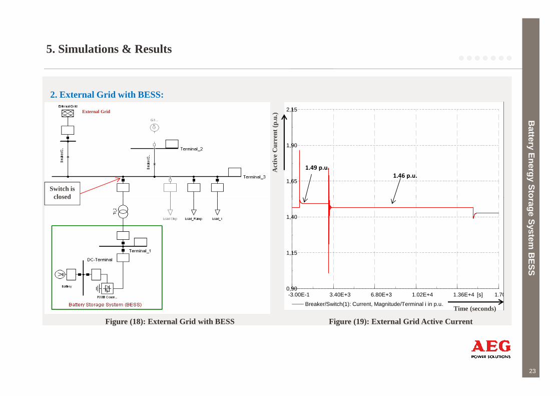
5. Simulations & Results
2. External Grid with BESS:
Battery E
nergy Storage S
ystem B
ES
S
2,15
1,90
1,65
Act
ive
Cur
rent
(p.
u.)External Grid
Switch isclosed
1.49 p.u.
1.46 p.u.
23
Battery E
nergy Storage S
ystem B
ES
S
Figure (18): External Grid with BESS
1.70E+41.36E+41.02E+46.80E+33.40E+3-3.00E-1 [s]
1,40
1,15
0,90
Breaker/Switch(1): Current, Magnitude/Terminal i in p.u.
Figure (19): External Grid Active Current
Time (seconds)
closed
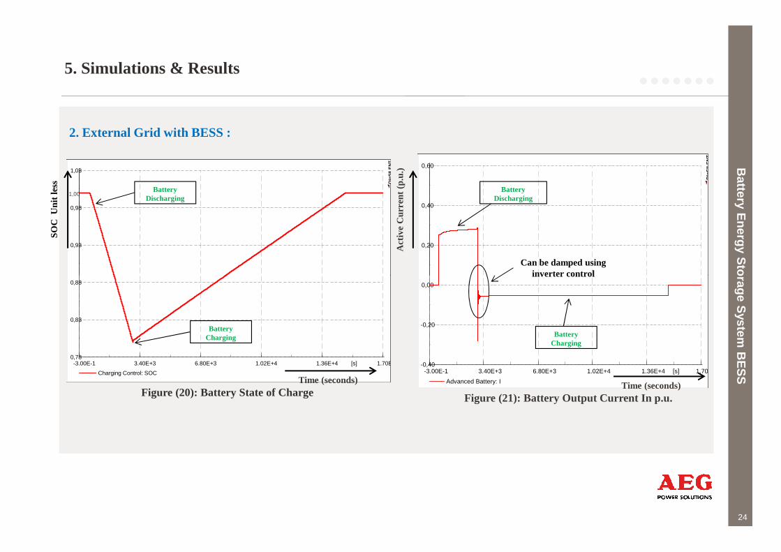
5. Simulations & Results
2. External Grid with BESS :
Battery E
nergy Storage S
ystem B
ES
S
1,03
0,98
0,93
DIg
SIL
EN
T
1,00
SOC
Uni
t le
ss
0,60
0,40
0,20
DIg
SIL
EN
T
Act
ive
Cur
rent
(p.
u.)
Battery Discharging
Battery Discharging
Can be damped usinginverter control
24
Battery E
nergy Storage S
ystem B
ES
S1.70E+41.36E+41.02E+46.80E+33.40E+3-3.00E-1 [s]
0,88
0,83
0,78
Charging Control: SOC
Figure (20): Battery State of ChargeTime (seconds)
1.70E+41.36E+41.02E+46.80E+33.40E+3-3.00E-1 [s]
0,00
-0,20
-0,40
Advanced Battery: I Time (seconds)
Battery Charging
Figure (21): Battery Output Current In p.u.
Battery Charging
inverter control
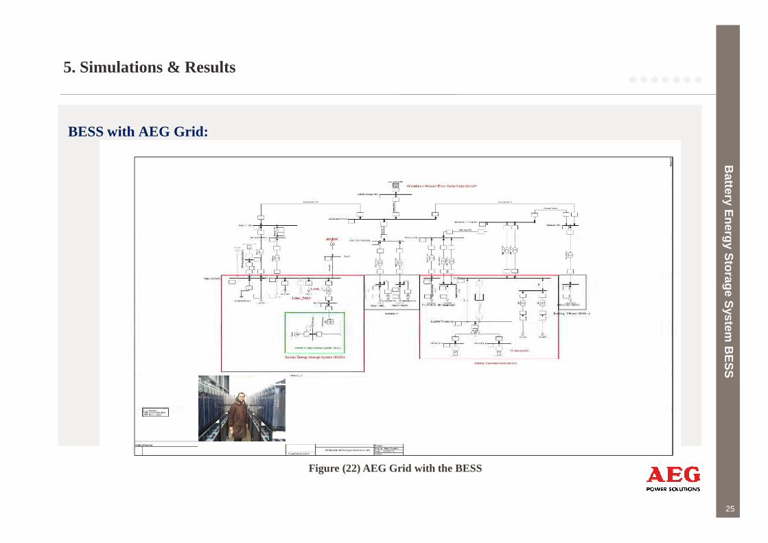
5. Simulations & Results
BESS with AEG Grid:
Battery E
nergy Storage S
ystem B
ES
S
25
Battery E
nergy Storage S
ystem B
ES
S
Figure (22) AEG Grid with the BESS
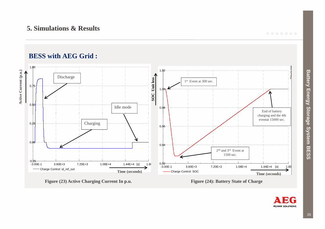
5. Simulations & Results
BESS with AEG Grid :
Battery E
nergy Storage S
ystem B
ES
S
1,02
1,00
0,98
DIg
SIL
EN
T1,00
0,75
0,50
1st Event at 300 sec.
End of battery charging and the 4th
SOC
Uni
t le
ss
Act
ive
Cur
rent
(p.
u.)
Discharge
Idle mode
26
Battery E
nergy Storage S
ystem B
ES
S
1.80E+41.44E+41.08E+47.20E+33.60E+3-3.00E-1 [s]
0,96
0,94
0,92
Charge Control: SOC
1.80E+41.44E+41.08E+47.20E+33.60E+3-3.00E-1 [s]
0,25
0,00
-0,25
Charge Control: id_ref_out
2nd and 3rd Event at1500 sec.
charging and the 4th eventat 15000 sec.
Time (seconds)Time (seconds)
Charging
Figure (24): Battery State of ChargeFigure (23) Active Charging Current In p.u.
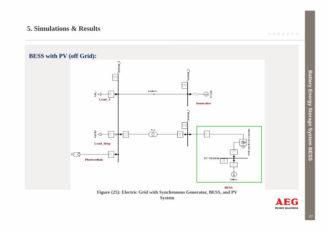
5. Simulations & Results
BESS with PV (off Grid):
Battery E
nergy Storage S
ystem B
ES
S
27
Battery E
nergy Storage S
ystem B
ES
S
Figure (25): Electric Grid with Synchronous Generator, BESS, and PV System

5. Simulations & Results
Battery E
nergy Storage S
ystem B
ES
S
Events:0,40
0,30
0,20
Act
ive
Pow
er (
MW
)
300 sec.
1000 sec.
28
Battery E
nergy Storage S
ystem B
ES
S
1440,01152,0863,96575,94287,92-0,1000 [s]
0,10
0,00
-0,10
Load Step: Active Power in MWLoad_1: Active Power in MW
Figure (26): Loads Active Power In MW
Time (seconds)
1000 sec.
5. Simulations & Results
Battery E
nergy Storage S
ystem B
ES
S
2,00
1,50
DIg
SIL
EN
T
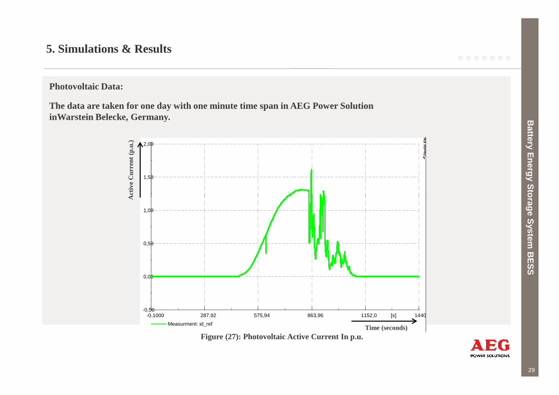
Photovoltaic Data:
The data are taken for one day with one minute time span in AEG Power Solution inWarstein Belecke, Germany.
Act
ive
Cur
rent
(p.u
.)
29
Battery E
nergy Storage S
ystem B
ES
S
1440,01152,0863,96575,94287,92-0,1000 [s]
1,00
0,50
0,00
-0,50
Measurment: id_refTime (seconds)
Act
ive
Figure (27): Photovoltaic Active Current In p.u.

5. Simulations & Results
Battery E
nergy Storage S
ystem B
ES
S
0,21
0,18
0,15
Act
ive
Pow
er (
MW
)0,99985
0,99960
0,99935
SOC
Uni
t le
ss
PV production increased
1000
300
sec.
30
Battery E
nergy Storage S
ystem B
ES
S
1440,01152,0863,96575,94287,92-0,1000 [s]
0,12
0,09
0,06
G3 (coal): Active Power in MW
Figure (29): Generator Active Power in MW
Time (seconds)
1440,01152,0863,96575,94287,92-0,1000 [s]
0,99910
0,99885
0,99860
Charging Control: SOCTime (seconds)
1000sec.
Figure (28): Battery State of Charge
PV production decreased
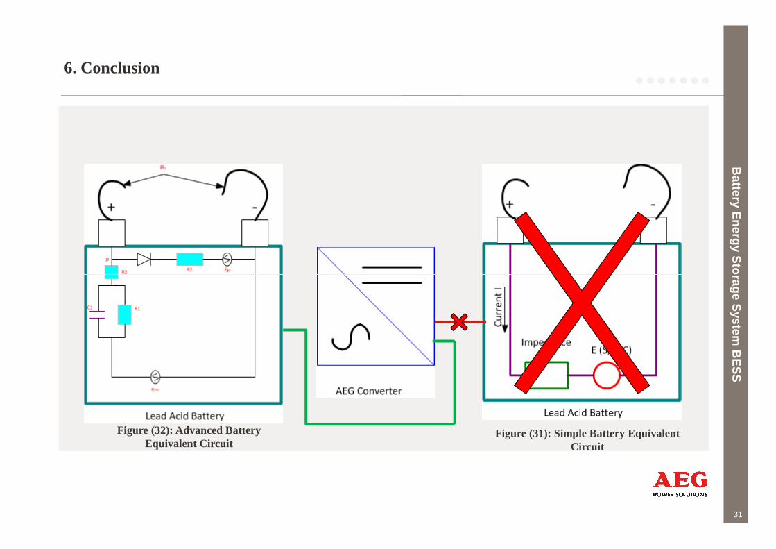
6. Conclusion
Battery E
nergy Storage S
ystem B
ES
S
31
Battery E
nergy Storage S
ystem B
ES
S
Figure (31): Simple Battery Equivalent Circuit
Figure (32): Advanced Battery Equivalent Circuit
6. Conclusion
Battery E
nergy Storage S
ystem B
ES
S
32
Battery E
nergy Storage S
ystem B
ES
S
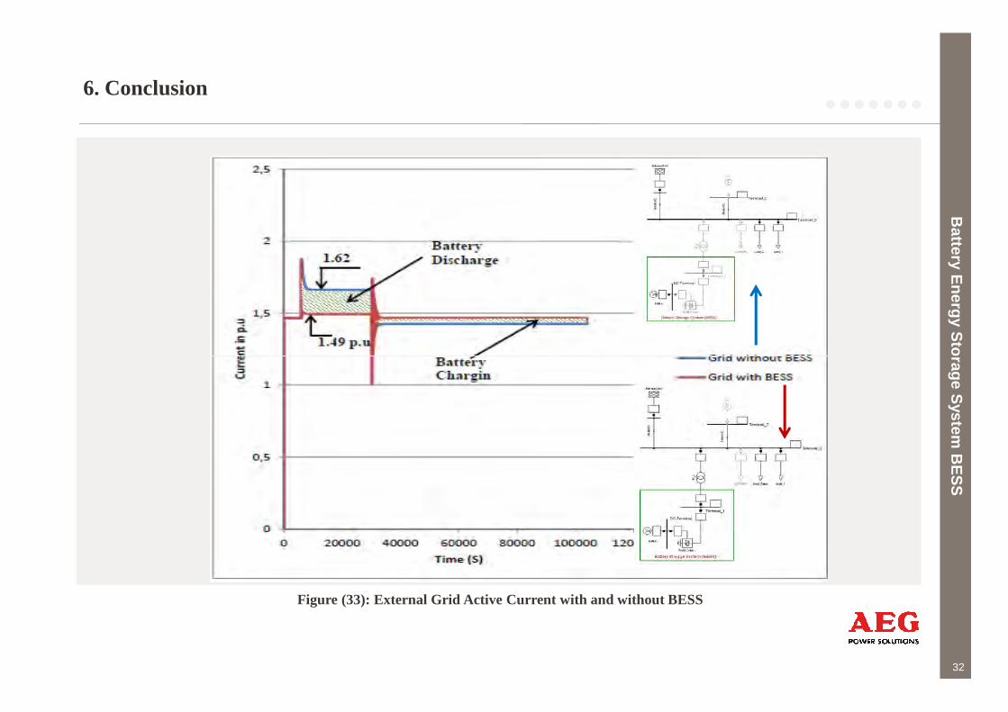
Figure (33): External Grid Active Current with and without BESS
7. Future Recommendations
7.1 PV DATA TAKEN EVERY SECOND.
7.2. CASE STUDY IN EGYPT.
7.3 INTEGRATION THE BATTERY LIFE TIME IN THE MODEL.
Battery E
nergy Storage S
ystem B
ES
S
33
Battery E
nergy Storage S
ystem B
ES
S
7. Future Recommendations
Battery E
nergy Storage S
ystem B
ES
S
7.1 PV DATA TAKEN EVERY SECOND:
For more realistic results of the PV simulation, PV data are required to be entered to the system
which should be taken with a one second time span for one complete day.
34
Battery E
nergy Storage S
ystem B
ES
S
7. Future Recommendations
Battery E
nergy Storage S
ystem B
ES
S
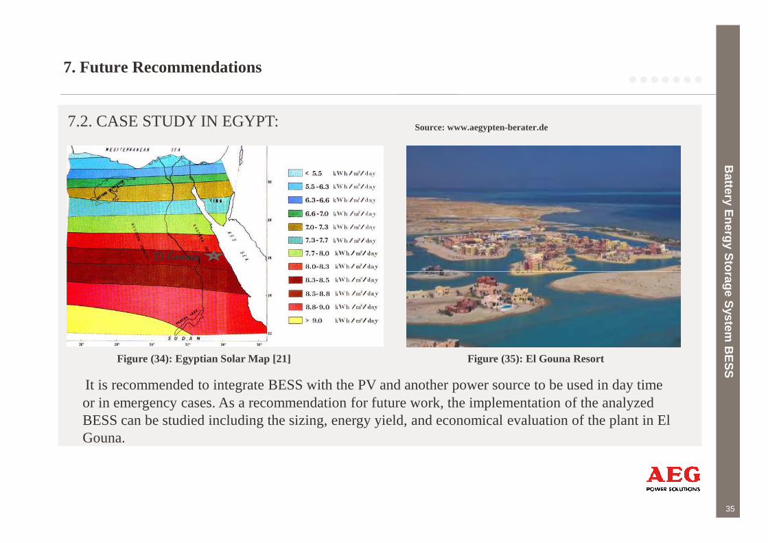
7.2. CASE STUDY IN EGYPT:
El Gouna
Source: www.aegypten-berater.de
35
Battery E
nergy Storage S
ystem B
ES
SFigure (34): Egyptian Solar Map [21]
It is recommended to integrate BESS with the PV and another power source to be used in day time or in emergency cases. As a recommendation for future work, the implementation of the analyzed BESS can be studied including the sizing, energy yield, and economical evaluation of the plant in El Gouna.
Figure (35): El Gouna Resort
7. Future Recommendations
Battery E
nergy Storage S
ystem B
ES
S
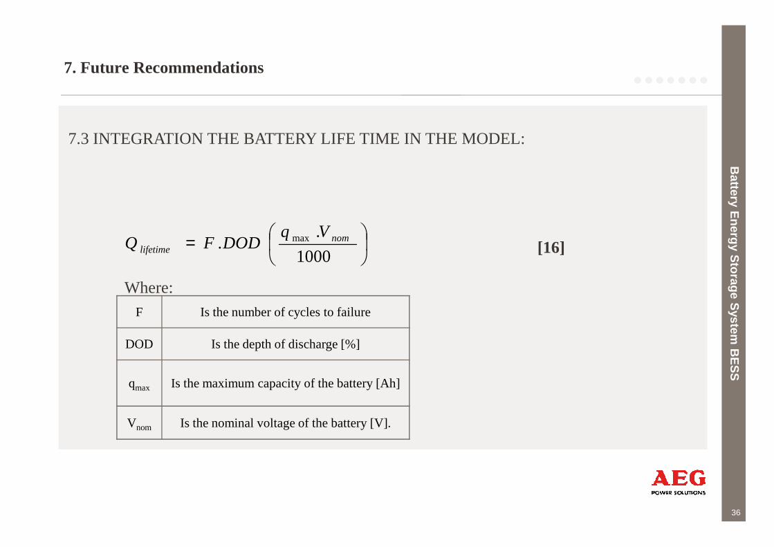
7.3 INTEGRATION THE BATTERY LIFE TIME IN THE MODEL:
=1000
.. max nom
lifetime
VqDODFQ [16]
36
F Is the number of cycles to failure
DOD Is the depth of discharge [%]
qmax Is the maximum capacity of the battery [Ah]
Vnom Is the nominal voltage of the battery [V].
Battery E
nergy Storage S
ystem B
ES
S
Where:
8. Summary
The main purpose of the study is to simulate the effect of the battery temperature, on the different
battery parameters and develop battery model that simulates the real reactions happens inside the
battery ,then integrate this model with different grids with different power sources.
Battery E
nergy Storage S
ystem B
ES
S
37
Battery E
nergy Storage S
ystem B
ES
S
Source: principlesofedu.wikispaces.com
9. References
1 Kenrik, V., 2012, Clean Power and Renewable Energy Growth in MENA Region,http://www.environmentalleader.com.
2 Goikoetxea1, A., Barrena1, J.A., Rodríguez, M.A., and Abad,G., March 2010, “Grid manager design using Battery Energy StorageSystems in weak power systems with high penetration of wind energy“, Proceedings of the tenth International Conference onRenewable Energies and Power Quality, Granada, Spain.
3 Kottick, D., Blau, M.,and Edelstein,D., 1993, Battery Energy Strorage for Frequency Regulation in an Island Power System, vol.8,3rd edition, IEEE Transactions on Energy Conversion.
4 Tsang, M.W., and Sutanto,D., 1998, “Control Strategies to Damp Inter-Area Oscillations Using a Battery Energy Storage System”,Department of Electrical Engineering, university of Hong Kong Polytechnic , Hung Hom, Hong Kong.
5 Electricity StorageAssociationwebsite, 2012, http://www.electricitystorage.org
Battery E
nergy Storage S
ystem B
ES
S
38
5 Electricity StorageAssociationwebsite, 2012, http://www.electricitystorage.org
6 Hageman, S.C., 1993 “Simple PSpice models let you simulate common battery types”, EDN, Oct. 28, 1993, pp.117-132.
7 Barak, M. (Ed.), Dickinson, T., Falk, U.,Sudworth, J.L.,Thirsk, H.R., Tye F.L., 1980, Electrochemical Power Sources: Primary &Secondary Batteries, IEE Energy Series 1, A. Wheaton &Co, Exeter.
8 Energiespeicher in Stromversorgungssystemen mit hohem Anteil erneuerbarer Energieträger“ VDE- Studie 2009.
9 Tammineedi,C., May2011, “Modelling Battery-Ultra-capacitor Hybrid Systems For Solar And Wind Applications”, The GraduateSchool, University of Pennsylvania, Pennsylvania, USA.
10 Toyota Motors Sales, 2012, Automotive batteries with questions,http://www.autoshop101.com.
Battery E
nergy Storage S
ystem B
ES
S
9. References
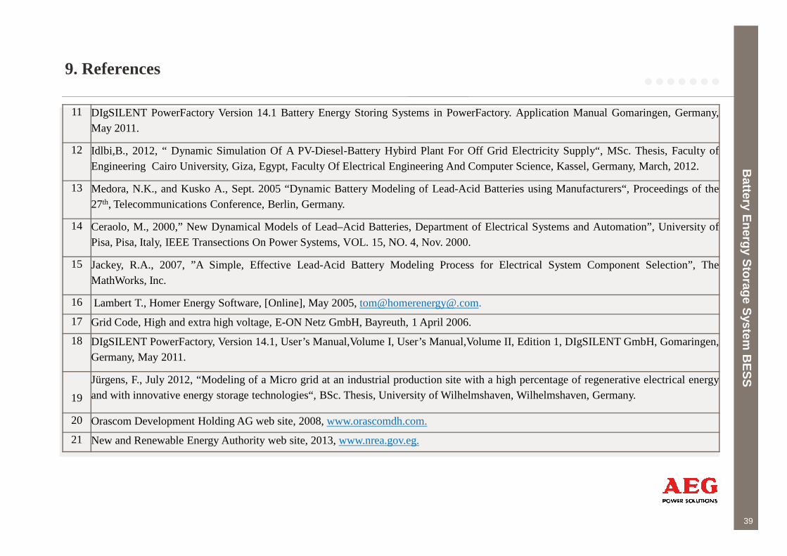
11 DIgSILENT PowerFactory Version 14.1 Battery Energy Storing Systems in PowerFactory. Application Manual Gomaringen, Germany,May 2011.
12 Idlbi,B., 2012, “ Dynamic Simulation Of A PV-Diesel-Battery Hybird Plant For Off Grid Electricity Supply“, MSc. Thesis, FacultyofEngineering Cairo University, Giza, Egypt, Faculty Of Electrical Engineering And Computer Science, Kassel, Germany, March, 2012.
13 Medora, N.K., and Kusko A., Sept. 2005 “Dynamic Battery Modeling of Lead-Acid Batteries using Manufacturers“, Proceedings of the27th, Telecommunications Conference, Berlin, Germany.
14 Ceraolo, M., 2000,” New Dynamical Models of Lead–Acid Batteries, Department of Electrical Systems and Automation”, UniversityofPisa, Pisa, Italy, IEEE Transections On Power Systems, VOL. 15, NO. 4, Nov. 2000.
15 Jackey, R.A., 2007, ”A Simple, Effective Lead-Acid Battery Modeling Process for Electrical System Component Selection”, TheMathWorks, Inc.
Battery E
nergy Storage S
ystem B
ES
S
39
MathWorks, Inc.
16 Lambert T., Homer Energy Software, [Online], May 2005,tom@[email protected].
17 Grid Code, High and extra high voltage, E-ON Netz GmbH, Bayreuth, 1 April 2006.
18 DIgSILENT PowerFactory, Version 14.1, User’s Manual,Volume I, User’s Manual,Volume II, Edition 1, DIgSILENT GmbH, Gomaringen,Germany, May 2011.
19
Jürgens, F., July 2012, “Modeling of a Micro grid at an industrial production site with a high percentage of regenerative electrical energyand with innovative energy storage technologies“, BSc. Thesis, University of Wilhelmshaven, Wilhelmshaven, Germany.
20 Orascom Development Holding AG web site, 2008,www.orascomdh.com.
21 Newand Renewable Energy Authority web site, 2013,www.nrea.gov.eg.
Battery E
nergy Storage S
ystem B
ES
S

Battery E
nergy Storage S
ystem B
ES
S
Thank You for Your
40
Battery E
nergy Storage S
ystem B
ES
S
2002 Stefan R. Müller . www.blinde-kuh.de
Thank You for Your
Attention
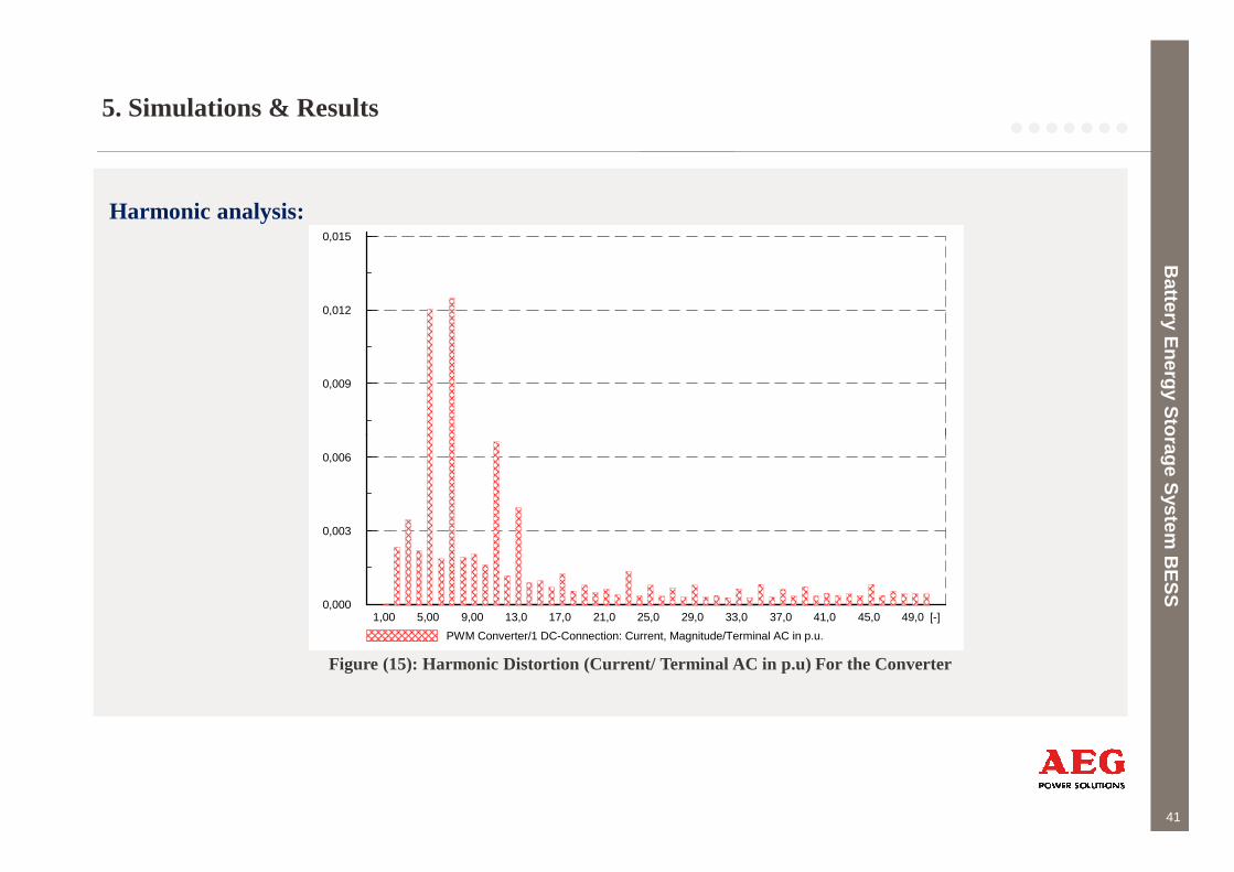
5. Simulations & Results
Harmonic analysis:
Battery E
nergy Storage S
ystem B
ES
S
0,015
0,012
0,009
41
Battery E
nergy Storage S
ystem B
ES
S
1,00 5,00 9,00 13,0 17,0 21,0 25,0 29,0 33,0 37,0 41,0 45,0 49,0 [-]
0,006
0,003
0,000
PWM Converter/1 DC-Connection: Current, Magnitude/Terminal AC in p.u.
Figure (15): Harmonic Distortion (Current/ Terminal AC in p.u) For the Converter

4. Models in Power Factory
1. Simple Model in Power Factory:
Battery E
nergy Storage S
ystem B
ES
S
Ucell =Uc-UR
42
Battery E
nergy Storage S
ystem B
ES
S
Figure (8): Simple Battery Model in Power Factory [11]
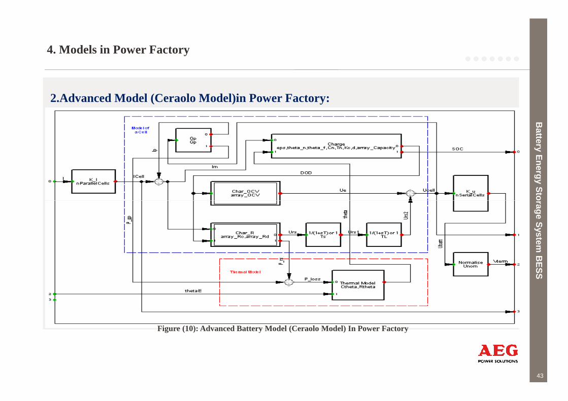
4. Models in Power Factory
2.Advanced Model (Ceraolo Model)in Power Factory:
Battery E
nergy Storage S
ystem B
ES
S
43
Battery E
nergy Storage S
ystem B
ES
S
Figure (10): Advanced Battery Model (Ceraolo Model) In Power Factory
44