Embed Size (px)
Citation preview

| ISS
N 2
542-
0542
Jour
nal o
f “A
lmaz
– A
ntey
” A
ir an
d Sp
ace
Def
ence
Cor
pora
tion
| No.
1, 2
020
10
| Electronics. Radio Engineering |
© Balakin D. A., Kersky E. V., 2020
https://doi.org/10.38013/2542-0542-2020-1-10-18UDC 621.396.969, 004.94
Development of a digital twin for an early-warning radar systemBalakin D. A., Kersky E. V.
Scientifi c Research Institute for Long-Distance Radio Communications (NIIDAR), OJSC, Moscow, Russian Federation
This article describes results of the development of a simplifi ed verifi cation model (SVM) for an early-warning radar system, which is the fi rst step to building a digital twin. An SVM is useful for the general understanding of the operating principles of a device, thus enabling the determination of hardware and software control pa-rameters. The article demonstrates that an SVM can be used for the development of calibration and phasing algorithms for the transmitting and receiving paths with respect to an external source and a reference signal. In addition, an SVM can simulate the processing of signals from various targets, such as aircraft or satellites. This article presents the architecture of the developed SVM and its control interface. SVMs can also be used to generate source data for the development of more complex models.
Keywords: digital twin, simplifi ed verifi cation model, electronic complex, analogue transceiver module, digital transceiver module
Для цитирования: Балакин Д. А., Керский Е. В. Разработка цифрового двойника радиолокационной станции дальнего обнаружения // Вестник Концерна ВКО «Алмаз – Антей». 2020. № 1. С. 10–18. https://doi.org/10.38013/2542-0542-2020-1-10-18
For citation: Balakin D. A., Kersky E. V. Development of a digital twin for an early-warning radar system // Journal of “Almaz – Antey” Air and Space Defence Corporation. 2020. No. 1. P. 10–18. https://doi.org/10.38013/2542-0542-2020-1-10-18
Submitted on 05.11.2019 Approved on 10.02.2020 Published on 21.05.2020
IntroductionThe modern pace of industry development de-mands fast and precise radar prototyping to en-hance the development quality. This task can be accomplished using the digital twin concept. Digi-tal twin is a binary model that simulates operation of a radar and its components in detail. Develop-ment of a radar system digital twin is an urgent task, as it allows to verify as many practical solu-tions as possible in minimal time and to prove them at the FEED stage. The digital twin must offer the properties of simulation modelling and answer the main question: how major operation-al characteristics (OC) of an article will change in various operation conditions. For instance, how to see the change in angular coordinate esti-mate, when each receive channel of the antenna
is out of phase, or how to estimate degrading ofanti-jamming algorithm when AFR of the receiver is non-linear. Prompt responses to such questions substantially save time for decision-making by the customer, chief designer or developer of the equipment.
In addition, the digital twin can be helpful to debug new radar control concepts and to prompt-ly implement them into the standard operation mode. Besides, the digital twin makes it possible to verify new digital signal processing methods and algorithms without the presence at the test object, which substantially saves time and la-bour costs. The digital twin also enables multiplerepetition of various experiments in anti-jamming, detection and identifi cation of complex targets and much more.
Certainly, development of a digital twin for an early-warning radar system is a complex and
| Ele
ctro
nics
. Rad
io E
ngin
eerin
g |
11
| ISSN 2542-0542 Journal of “Almaz – Antey” Air and Space Defence Corporation | No. 1, 2020
labour-intensive process that may be comparable to the process of development of a real radar sys-tem in terms of time. However, the above advan-tages are worth the time and money spent. The article considers a simplifi ed verifi cation model (SVM) that is an initial approximation to the dig-ital twin. The key advantage of an SVM is the fact that it refl ects design and physical peculiarities of hardware of the early-warning radar system being developed. Design features may include: radar di-mensions, general structure and type of antenna curtain, in particular, type of emitters and distance between them, switching of analogue and digital signals of transceivers, radiation pattern genera-tion method (the digital method as applied to this model) and much more. Physical features include the parameters determined in technical specifi ca-tions for analogue and digital transceivers: trans-mission ratios of the transceiver channel, AFR and PFR of the transceiver path, noise factor, etc. The SVM was developed in the Matrix Laboratory (MATLAB) package. Due to the elaborated math-ematical tool, MATLAB is well suited to simulate not just individual radar components, but also the article as a whole. In particular, MATLAB pack-age also includes libraries, such as Phased Array system toolbox, Antenna toolbox, DSP system toolbox and much more, to facilitate fast and precise simulation of features of the article being developed [1]. It is also worth noting that MAT-LAB programming language itself became a tool of communication among the scientifi c commu-nity all over the world [2].
From the simulation perspective, the most notable is Simulink utility that is a part of MAT-LAB package. Simulink enables simulation of an article and its components in a visual form. This, in turn, enables a high level of understanding of general operation principles of the radar system being developed.
Let us consider the SVM architecture.
SVM architectureThe SVM block diagram is shown in Figure 1.
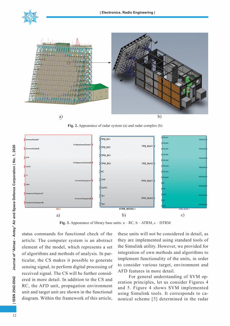
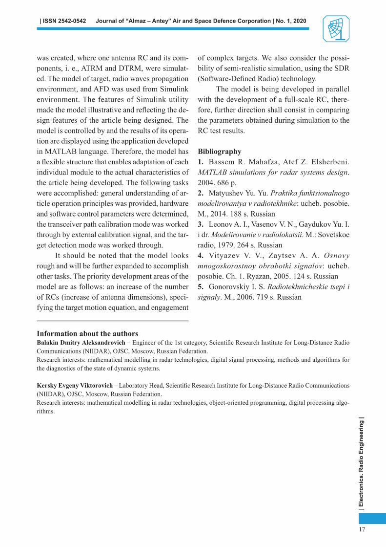
The major structural element of SVM is antenna radar complex (RC) (RC appearance is shown in Fig. 2b) that consists of both analogue transceiver modules (ATRMs) and digital trans-ceiver modules (DTRMs). Essentially, RC is a de-sign unit of the radar system (Fig. 2a). A set of tens or hundreds of RCs can simulate a full-fl edged radar system. Therefore, based on the Simulink utility, we have developed an RC library unit(Fig. 3), that makes it possible to use it togeth-er with standard units provided for in Simulink,e. g., target, environment, and antenna and feeder device (AFD). In turn, RC is based on the ATRM and DTRM that determine physical features of ra-dar system operation. They are also implemented in the form of library elements (Fig. 3).
It should be noted that one RC contains64 ATRMs and 32 DTRMs, and there are about thousands of them in a full-fl edged radar system. The functional diagram shows a computer system (CS) that generates control commands for model components. The CS also analyses the received
---
----
-
-
1
1
Fig. 1. Functional diagram of the model of the radar system consisting of one RC in the target engagement mode
| ISS
N 2
542-
0542
Jour
nal o
f “A
lmaz
– A
ntey
” A
ir an
d Sp
ace
Def
ence
Cor
pora
tion
| No.
1, 2
020
12
| Electronics. Radio Engineering |
status commands for functional check of the article. The computer system is an abstract element of the model, which represents a set of algorithms and methods of analysis. In par-ticular, the CS makes it possible to generate sensing signal, to perform digital processing of received signal. The CS will be further consid-ered in more detail. In addition to the CS and RC, the AFD unit, propagation environment unit and target unit are shown in the functional diagram. Within the framework of this article,
these units will not be considered in detail, as they are implemented using standard tools of the Simulink utility. However, we provided for integration of own methods and algorithms to implement functionality of the units, in order to consider various target, environment and AFD features in more detail.
For general understanding of SVM op-eration principles, let us consider Figures 4and 5. Figure 4 shows SVM implemented using Simulink tools. It corresponds to ca-nonical scheme [3] determined in the radar
Fig. 2. Appearance of radar system (a) and radar complex (b)
Fig. 3. Appearance of library base units: a – RC, b – ATRM, c – DTRM
a) b)
a) b)
c)

| Ele
ctro
nics
. Rad
io E
ngin
eerin
g |
13
| ISSN 2542-0542 Journal of “Almaz – Antey” Air and Space Defence Corporation | No. 1, 2020
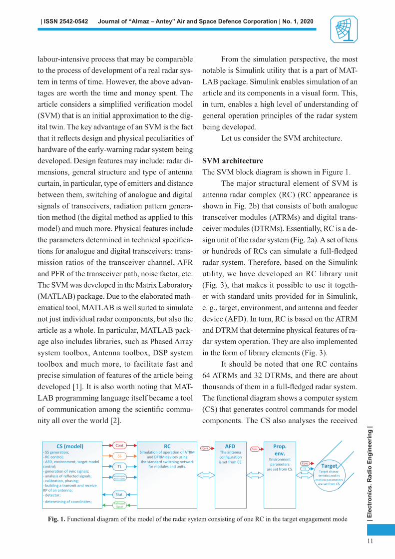
Fig. 5. Radar complex divided by subsystems
technology theory. Figure 5 discloses the RC diagram (transceiver, hardware portion of the RC, i.e. subsystem 9) in more detail as appli-cable to Simulink model.
The signal generator generates a sens-ing signal (SS) in two polarizations (thus, themodel has the total of 128 channels: 64 hori-zontal and 64 vertical), while the type and
parameters of the SS are set both by standard Simulink generators and using the CS where a SS of arbitrary type can be generated. Fur-ther, the SS is received in the transmit path of the RC trough DTRM to the ATRM (in Figure 4, this is the transmitter). Propagation of the SS in DTRM and ATRM lines is provided by subsystem 6 in Figure 5. Subsystem 7 further propagates the signal from the RC transmit path to environment and target units (an in-terference component is included in units and modules). Then, reflected signal is received by the RC receive path (receiver in Figure 4) from ATRM to DTRM. In turn, signal propa-gation through the RC receive path is provided by subsystem 5. Subsystem 8 propagates the reflected signal for further analysis using the CS (signal processing).
Fig. 4. Scheme of simplifi ed verifi cation model generation

| ISS
N 2
542-
0542
Jour
nal o
f “A
lmaz
– A
ntey
” A
ir an
d Sp
ace
Def
ence
Cor
pora
tion
| No.
1, 2
020
14
| Electronics. Radio Engineering |
Figure 5 shows 8 analogue units (corre-sponds to 1) and 4 digital units (corresponds to 2). Note that signals from two analogue units are received in one digital unit, and, in a similar way, outputs of the digital unit pro-vide two analogue units. In turn, each of the units contains 8 ATRMs and DTRMs shown inFigure 3. Development of additional subsys-tems of analogue and digital units is condi-tioned upon improvement of model readability. The analogue transceiver module performs the following functions: filtering, attenuation, and pre-amplification. It also considers non-linear elements and noise effects. The digital trans-ceiver module provides digital-to-analogue conversion, analogue-to-digital conversion, at-tenuation, frequency conversion, signal filter-ing, and multi-rate processing [4]. The DTRM also features compensation algorithms for sig-nal delays that may arise in the transceiver path. Calculation of signal delays of transmit and receive paths of the PAA is performed by the external emitter/receiver and is implement-ed in the computer system.
Control parameters are distributed by each ATRM and DTRM using subsystem 3.
Let us simulate the following case: an SS is sent to the RC from an external source through the environment. Due to mismatch of cable lengths or ADC mal-synchronisation, sudden delays may occur in each of the receive channels, which, in turn, may impact the re-ceive radiation pattern. Using such operation mode, the radar system calibration and phas-ing situation can be simulated (Fig. 6a and b).
The SVM provides for various methods for calculation of signal delays. Let us consider them briefl y (in all methods, one signal is the reference to calculate the delay):
- the method based on cross-correlation in-tegral calculation [5] (hereinafter referred to as the correlation method);
- the method based on spectral analysis cal-culates spectra of two signals, further fi nds num-bers of fi lters with maximum spectra, and inserts them as indices into the calculation of differ-ence between phase frequency characteristics [5](hereinafter referred to as the spectral method);
Fig. 6. SVM operation results: a and c – receive signal, b and d – radiation pattern
b)
c) d)

| Ele
ctro
nics
. Rad
io E
ngin
eerin
g |
15
| ISSN 2542-0542 Journal of “Almaz – Antey” Air and Space Defence Corporation | No. 1, 2020
- the method based on Hilbert transforma-tion performs Hilbert transformation of signals, further calculates the phase of ratio between trans-formation results [5] (hereinafter referred to as the Hilbert method);
- the method based on properties of the LFM signal performs heterodyning between the refer-ence signal and the delayed signal, further calcu-lates the spectrum where it fi nds the maximum fi lter value, by the value of which the signal delay is calculated (hereinafter referred to as the LFM method).
Figure 7 shows the results of processing us-ing the above methods.
Model operation results suggest the follow-ing conclusions: the correlation method provides the highest error of signal delay calculation (Fig. 7a, the dot-and-dash line). The advantage of this method is its simple implementation. The spectral
method and Hilbert method provide very close es-timates of signal delay (Fig. 7b), but these meth-ods fail to accomplish the task, when the delay exceeds the whole signal cycle. In addition, these methods are very sensitive to noise and interfer-ence components. The method based on LFM signal properties is free from the above shortcom-ings, however it is more diffi cult to implement.
As an LFM signal is used as the SS, we turn our attention to the LFM method for further analy-sis. After calculation of signal delays in the trans-ceiver path, they need to be compensated. The compensation is performed in DTRM. The delay matrix was calculated for this purpose (Fig. 8).
Each column of the matrix is a set of signal delays in all channels, the column number stands for the channel, which the delays are compen-sated for. Thus, the elements of selected column are recorded to DTRM, where compensation for
Fig. 8. Delay matrix
Fig. 7. Model operation results: a – delay calculation, b – calculation of delay around channel 25; 1 – true signal delay, 2 – delay calculated using the correlation method, 3 – delay calculated using the spectral method, 4 – delay calculated
using the Hilbert method, 5 – delay calculated using the LFM method; Ch – channel number, T – signal delay

| ISS
N 2
542-
0542
Jour
nal o
f “A
lmaz
– A
ntey
” A
ir an
d Sp
ace
Def
ence
Cor
pora
tion
| No.
1, 2
020
16
| Electronics. Radio Engineering |
signal delay is performed. The results of time de-lay compensation are shown in Figures 6c and d.
Further, let us consider the SVM control structure and interface.
SVM control structure and interfaceThe developed simplifi ed verifi cation model is controlled using a special structure, i. e. con-trol structure. Essentially, the control structure is an array of structures, where the RC number is the index. In turn, the RC structure includes the following components:
- the array of ATRM control structures, where each structure stores own value of control parameters of one ATRM, such as transmission ratio, fi lter ratios, AFR, etc. Therefore, in the SVM model, each ATRM may have its control parameters, to adapt modules to features of real ATRMs, thus, approximating SVM to a real ra-dar system;
- the array of DTRM control structures, where, just like in ATRMs, each DTRM can be controlled separately, e.g., through adjusting the transceiver signal delay, setting digital fi l-ter ratios, and adjusting the signal bandwidth;
- the target structure that contains target control parameters: RCS, range, velocity, etc.;
- the environment structure that contains propagation environment control parameters:
ground reflection factor, delays, number of bands, etc.
Further, let us consider the control inter-face shown in Figure 9.
Essentially, the shown interface repre-sents the CS shell. As you can see, the control interface has quite an extensive set of options to preset various modes of received informa-tion display through enabling or disabling of both ATRM and DTRM, and much more. TheModel List tab calls its control interface: gen-eration of sensing signal, target, environment, antenna, RC, ATRM and DTRM. It also pro-vides for the target engagement mode, where standard units of Simulink utility are used as the propagation environment and the target. As an example, let us consider the following case: two targets with different RCS are located at various distances. The fi rst target was located at a dis-tance of approximately 1,000 m, another target was located at 2,000 m, while radial velocity of the targets was different. The received sig-nal was processed and displayed using standard units of Simulink utility. The processing result is shown in Figure 10.
ConclusionAt the initial stage of a radar station digital twin development, the simplifi ed verifi cation model
Fig. 9. Appearance of SVM control interface Fig. 10. Target engagement mode
| Ele
ctro
nics
. Rad
io E
ngin
eerin
g |
17
| ISSN 2542-0542 Journal of “Almaz – Antey” Air and Space Defence Corporation | No. 1, 2020
was created, where one antenna RC and its com-ponents, i. e., ATRM and DTRM, were simulat-ed. The model of target, radio waves propagation environment, and AFD was used from Simulink environment. The features of Simulink utility made the model illustrative and refl ecting the de-sign features of the article being designed. Themodel is controlled by and the results of its opera-tion are displayed using the application developed in MATLAB language. Therefore, the model has a fl exible structure that enables adaptation of each individual module to the actual characteristics of the article being developed. The following tasks were accomplished: general understanding of ar-ticle operation principles was provided, hardware and software control parameters were determined, the transceiver path calibration mode was worked through by external calibration signal, and the tar-get detection mode was worked through.
It should be noted that the model looks rough and will be further expanded to accomplish other tasks. The priority development areas of the model are as follows: an increase of the number of RCs (increase of antenna dimensions), speci-fying the target motion equation, and engagement
of complex targets. We also consider the possi-bility of semi-realistic simulation, using the SDR (Software-Defi ned Radio) technology.
The model is being developed in parallel with the development of a full-scale RC, there-fore, further direction shall consist in comparing the parameters obtained during simulation to the RC test results.
Bibliography1. Bassem R. Mahafza, Atef Z. Elsherbeni.MATLAB simulations for radar systems design. 2004. 686 р.2. Matyushev Yu. Yu. Praktika funktsionalnogo modelirovaniya v radiotekhnike: ucheb. posobie. M., 2014. 188 s. Russian3. Leonov A. I., Vasenov V. N., Gaydukov Yu. I. i dr. Modelirovanie v radiolokatsii. M.: Sovetskoe radio, 1979. 264 s. Russian4. Vityazev V. V., Zaytsev A. A. Osnovy mnogoskorostnoy obrabotki signalov: ucheb.posobie. Ch. 1. Ryazan, 2005. 124 s. Russian5. Gonorovskiy I. S. Radiotekhnicheskie tsepi i signaly. M., 2006. 719 s. Russian
Information about the authorsBalakin Dmitry Aleksandrovich – Engineer of the 1st category, Scientifi c Research Institute for Long-Distance Radio Communications (NIIDAR), OJSC, Moscow, Russian Federation.Research interests: mathematical modelling in radar technologies, digital signal processing, methods and algorithms for the diagnostics of the state of dynamic systems.
Kersky Evgeny Viktorovich – Laboratory Head, Scientifi c Research Institute for Long-Distance Radio Communications (NIIDAR), OJSC, Moscow, Russian Federation.Research interests: mathematical modelling in radar technologies, object-oriented programming, digital processing algo-rithms.
| ISS
N 2
542-
0542
Jour
nal o
f “A
lmaz
– A
ntey
” A
ir an
d Sp
ace
Def
ence
Cor
pora
tion
| No.
1, 2
020
18
| Electronics. Radio Engineering |
Разработка цифрового двойника радиолокационной станции дальнего обнаружения
Д. А. Балакин, Е. В. КерскийОткрытое акционерное общество «Научно-производственный комплекс “Научно-исследовательский институт дальней радиосвязи”», Москва, Российская Федерация
В статье обсуждаются результаты разработки упрощенной верификационной модели (УВМ) РЛС дальнего обнаружения, которая является первым шагом к построению цифрового двойника. УВМ способствует общему пониманию принципов работы изделия, а также позволяет определить параметры управления аппаратурой и программным обеспечением. В статье показано, что с помощью УВМ можно отработать алгоритмы калибровки и фазировки передающего и приемного тракта по внешнему источнику, по контрольному сигналу. Также УВМ позволяет имитировать обработку сигналов от различных целей: самолетов или спутников. В статье представлена архитектура построения УВМ и ее интерфейс управления. Также УВМ позволяет сформировать исходные данные для разработки более сложных моделей.
Ключевые слова: цифровой двойник, упрощенная верификационная модель, радиоэлектронный комплекс, аналоговый приемо-передающий модуль, цифровой приемо-передающий модуль
Об авторахБалакин Дмитрий Александрович – инженер 1-й категории Открытого акционерного общества «Научно-производственный комплекс “Научно-исследовательский институт дальней радиосвязи”», Москва, Российская Федерация.Область научных интересов: математическое моделирование в радиолокации, цифровая обработка сигналов, методы и алгоритмы диагностики состояния динамических систем.
Керский Евгений Викторович – начальник лаборатории Открытого акционерного общества «Научно-производственный комплекс “Научно-исследовательский институт дальней радиосвязи”», Москва, Российская Федерация.Область научных интересов: математическое моделирование в радиолокации, объектно-ориентированное программирование, алгоритмы цифровой обработки.