Embed Size (px)
Citation preview
Research ArticleDevelopment of a New Robotic Ankle Rehabilitation Platform forHemiplegic Patients after Stroke
Quanquan Liu ,1,2,3,4,5 Chunbao Wang ,1,2,3,4,5 Jian Jun Long ,2 Tongyang Sun ,3
Lihong Duan,1 Xin Zhang ,2 Bo Zhang ,4,6 Yajing Shen ,7 Wanfeng Shang ,1
Zhuohua Lin ,4 Yulong Wang ,2 Jinfeng Xia ,5 Jianjun Wei ,5 Weiguang Li ,3
and Zhengzhi Wu 1
1Shenzhen Institute of Geriatrics, Shenzhen, China2The Second People’s Hospital of Shenzhen, Shenzhen, China3The School of Mechanical & Automotive Engineering, South China University of Technology, Guangzhou, China4Faculty of Science and Engineering, Waseda University, Tokyo, Japan5The School of Mechanical Engineering, Guangxi University of Science and Technology, Liuzhou, China6The Beijing Advanced Innovation Center for Intelligent Robots and Systems, Beijing Institute of Technology, Beijing, China7Mechanical and Biomedical Engineering Department, City University of Hong Kong, Hong Kong
Correspondence should be addressed to Yulong Wang; [email protected] and Zhengzhi Wu; [email protected]
Received 26 April 2017; Accepted 13 November 2017; Published 15 March 2018
Academic Editor: Saverio Affatato
Copyright © 2018 Quanquan Liu et al. This is an open access article distributed under the Creative Commons Attribution License,which permits unrestricted use, distribution, and reproduction in any medium, provided the original work is properly cited.
A large amount of hemiplegic survivors are suffering from motor impairment. Ankle rehabilitation exercises act an important rolein recovering patients’ walking ability after stroke. Currently, patients mainly perform ankle exercise to reobtain range of motion(ROM) and strength of the ankle joint under a therapist’s assistance by manual operation. However, therapists suffer from highwork intensity, and most of the existed rehabilitation devices focus on ankle functional training and ignore the importance ofneurological rehabilitation in the early hemiplegic stage. In this paper, a new robotic ankle rehabilitation platform (RARP) isproposed to assist patients in executing ankle exercise. The robotic platform consists of two three-DOF symmetric layer-stackingmechanisms, which can execute ankle internal/external rotation, dorsiflexion/plantarflexion, and inversion/eversion exercisewhile the rotation center of the distal zone of the robotic platform always coincides with patients’ ankle pivot center. Threeexercise modes including constant-speed exercise, constant torque-impedance exercise, and awareness exercise are developed toexecute ankle training corresponding to different rehabilitation stages. Experiments corresponding to these three ankle exercisemodes are performed, the result demonstrated that the RARP is capable of executing ankle rehabilitation, and the novelawareness exercise mode motivates patients to proactively participate in ankle training.
1. Introduction
Recently, a large number of stroke survivors are sufferingfrommotor impairment. The recovery of motor loss functionis difficult conducted only by biomedical treatment [1]. Gen-erally, ankle rehabilitation after stroke consists of three stages[2]. In the first stage, known as the first month after stroke,patients mainly play simple and passive training in bed. Inthe second stage, patients begin to participate in active
rehabilitation exercises, including balance and coordinationtraining to strengthen the affected ankle. In the third stage,patients try to reobtain their healthy state through inten-sive rehabilitation training. The first two stages aim toavoid patient muscle atrophy, and the third stage focuseson improving patients’ life quality. To stroke survivors,rehabilitation at the first two stages plays an importantrole in recovering their walk ability by exercising theaffected muscles [3, 4].
HindawiJournal of Healthcare EngineeringVolume 2018, Article ID 3867243, 12 pageshttps://doi.org/10.1155/2018/3867243
In the traditional ankle exercise, physiotherapy (PT)manually holds patients’ affected ankle to carry out inter-nal/external rotation, dorsiflexion/plantarflexion, and inver-sion/eversion motion during ankle rehabilitation. Thismanual training method makes PT exhausted, and the reha-bilitation performance highly relies on a physiotherapist’sexperience. Furthermore, patients may act confrontation onthis passive training method which reduces the rehabilitationefficiency. In order to address the manipulation challenges inankle rehabilitation, many studies have considered the devel-opment of robotic systems to reduce a physiotherapist’sworkload and enhance patients’ rehabilitation performance.A parallel structure robotic system and an exoskeletal struc-ture robotic system are the two main research interests inthe ankle rehabilitation assistance.
Saglia et al. reported a two-DOF foot pedal using parallelstructure for ankle rehabilitation [2]. It can achieve ankledorsiflexion/plantarflexion and inversion/eversion exercisesunder position control for patient-passive exercise mode orunder admittance control for patient-active exercise mode.Rutgers University developed a 6-DOF ankle rehabilitationrobot “Rutgers ankle” based on a Stewart platform drivenby pneumatic actuation, where a 6-DOF force sensor wasused to provide force and torque feedback generated betweenthe patient’s foot and the foot pedal [5]. Liu et al. announceda 3-RSS/S parallel robotic platform associated with a virtualtraining environment, which employed servo motor to driveits parallel links [6]. Meng et al. constructed a parallel struc-ture ankle rehabilitation robot, where the patient’s leg is fixedto the base of the robot; therefore, the robot can drive thepatient’s foot to generate relative movement using the anklejoint as the pivot center [7]. Muhammad and Shafrizapresented a mechanical design and kinematic analysis of aparallel robot for ankle rehabilitation [8]. Yu et al. presenteda 3-DOF cable-driven parallel robot for ankle rehabilitation.The mechanical design ensured that the mechanism centerof the rotations can match the ankle axes of rotations [9].
Besides the parallel structure robotic ankle rehabilitationrobot, a number of exoskeletal structure ankle rehabilitationrobots were also developed. Jeffrey et al. presented a poweredankle-foot orthosis. The device owns only one DOF to realizeankle dorsiflexion/plantarflexion training [10]. DelawareUniversity developed a wearable exoskeletal ankle rehabilita-tion robot to assist dorsiflexion/plantarflexion and inversion/eversion training [11]. Rahman and Ikeura developed adynamic knee-ankle-foot orthosis to offer variable-impedance dorsiflexion/plantarflexion training using awrap-spring clutch [12]. Hong et al. introduced a 3-DOFankle rehabilitation robot, which consisted of a parallelconnection of a spherical five-bar linkage and a revolute-spherical-universal serial chain to assist ankle dorsiflexion/plantarflexion and inversion/eversion training [13].
The summary of the existing state-of-the-art parallelstructure ankle rehabilitation robots and exoskeletal anklerehabilitation robots can be found in Table 1.
Through examining the existing robots for ankle rehabil-itation, a few improvements could still be identified as fol-lows: (1) the rotation center of the foot pedal should easilypoint to the rotation center of the ankle joint via mechanical
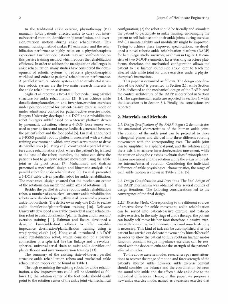
configuration; (2) the robot should be friendly and stimulatethe patient to participate in ankle training, encouraging thepatient to self-balance both their ankle joints during exercise;and (3) maintainability and modularity might be improved.Trying to achieve these improved specifications, we devel-oped a novel robotic ankle rehabilitation platform (RARP)for hemiplegic stroke survivors, as shown in Figure 1. It con-sists of two 3-DOF symmetric layer-stacking structure plat-forms; therefore, the mechanical configuration allows thepatient to use his/her sound side ankle joint to teach theaffected side ankle joint for ankle exercises under a physio-therapist’s instructions.
This paper is organized as follows. The design specifica-tion of the RARP is presented in Section 2.1, while Section2.2 is dedicated to the mechanical design of the RARP. Andthe control architecture of the RARP is described in Section2.4. The experimental results are reported in Section 3, whilethe discussion is in Section 3.4. Finally, the conclusions arereported.
2. Materials and Methods
2.1. Design Specification of the RARP. Figure 2 demonstratesthe anatomical characteristics of the human ankle joint.The rotation of the ankle joint can be projected to threeorthogonal planes and divided into three different rotatingmovements with the corresponding axes. The ankle jointcan be simplified as a spherical joint, and the rotation alongthe x-axis is to achieve inversion/eversion movement, whilethe rotation along the y-axis is to obtain dorsiflexion/plantar-flexion movement and the rotation along the z-axis is to real-ize internal/external rotation. Considering the individualdifference of ankle physiological characteristics, the range ofeach ankle motion is shown in Table 2 [14, 15].
2.2. Design Consideration and Iterations. The final design ofthe RARP mechanism was obtained after several rounds ofdesign iterations. The following considerations led to theconvergence of the final design.
2.2.1. Exercise Mode. Corresponding to the different sourcesof tractive force for ankle movement, ankle rehabilitationcan be sorted into patient-passive exercise and patient-active exercise. In the early stage of ankle therapy, the patientcan hardly self-move his/her foot; therefore, a passive exer-cise with constant-speed movement to avoid muscle atrophyis necessary. This kind of task can be accomplished after thepatient has carried out delicate movement by himself/herself.In order to allow the patient to fully reobtain his/her motorfunction, constant torque-impedance exercises can be exe-cuted with the device to enhance the strength of the patient’saffected muscles.
To the above exercise modes, researchers pay most atten-tions to recover the range of motion and force strength of thepatient’s affected ankle; however, ankle exercise contentshould consider the balance and the coordination betweenthe sound side ankle and the affected side ankle due to theindividual differences. Hence, in this paper, we propose anew ankle exercise mode, named as awareness exercise that
2 Journal of Healthcare Engineering
allows the patient to train his/her affected side ankle using themotor parameters obtained from his/her sound side ankle.With this exercise mode, the motor capability of the affectedside ankle will approach that of the sound side ankle; there-fore, it allows the patient to regain symmetric balance capa-bility for walking after ankle exercise.
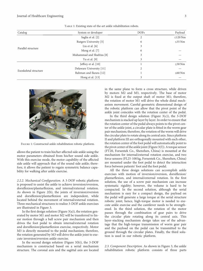
2.2.2. Mechanical Configuration. A 3-DOF robotic platformis proposed to assist the ankle to achieve inversion/eversion,dorsiflexion/plantarflexion, and internal/external rotation.As shown in Figure 2(b), the joints of inversion/eversionand dorsiflexion/plantarflexion are independent, whilelocated behind the movement of internal/external rotation.Three mechanical structures to realize 3-DOF ankle exercisesare illustrated in Figure 3.
In the first design solution (Figure 3(a)), the rotation gen-erated by motor M1 and motor M2 will be transferred to lin-ear motion through a ball screw pair mechanism and thendrives the foot pedal to obtain internal/external rotationand dorsiflexion/plantarflexion exercise, respectively. MotorM3 is directly mounted to the pedal mechanism; therefore,the rotation generated by M3 will drive the ankle joint to exe-cute inversion/eversion ankle exercise.
In the second design solution (Figure 3(b)), the 3-DOFmechanism is constructed based on a serial mechanismstructure. The coronal axis and the sagittal axis are located
in the same plane to form a cross structure, while drivenby motors M2 and M3, respectively. The base of motorM2 is fixed at the output shaft of motor M1; therefore,the rotation of motor M1 will drive the whole distal mech-anism movement. Careful geometric dimensional design ofthe robotic platform can allow that the pivot point of theankle joint coincides with the rotation center of the pedal.
In the third design solution (Figure 3(c)), the 3-DOFmechanism is stacked up layer by layer. In order to ensure thatthe rotation center of the pedal always points to the pivot cen-ter of the ankle joint, a circular plate is fitted in the worm gearpairmechanism; therefore, the rotation of the wormwill drivethe circular plate to rotate along its central axis. Since platformII and platform III are orthogonally mounted with each other,the rotation center of the foot pedal will automatically point tothepivot center of the ankle joint (Figure 3(f)).A torque sensor(FT20, Forsentek Co., Shenzhen, China) is mounted at themechanism for internal/external rotation exercise, and twoforce sensors (FL25-100 kg, Forsentek Co., Shenzhen, China)are mounted under the foot pedal to detect the interactionforce between patients’ foot and the foot pedal.
All the three design solutions can accomplish ankleexercises with motion of inversion/eversion, dorsiflexion/plantarflexion, and internal/external rotation. In the firstsolution, the use of a screw pair mechanism can increasesystematic rigidity; however, the volume is hard to becompacted. In the second solution, although the serialmechanism is easy for a compact design, the payload onthe pedal will generate a large torque at the serial structurerobotic joint; hence, high-torque motor is needed to exe-cute ankle exercise and the cantilever needs to be strength-ened. In the third solution, the rotation of the motorpasses through the combination of gear pairs to drivethe circular plate rotating along its central axis. Thislayer-stacking mechanism design takes use of the advan-tage that the high-torque transmission of worm gear pairand the payload on the pedal can be transmitted to theground through the circular plates. Finally, the third solu-tion is used in our robotic platform.
2.3. Component Description. As shown in Figure 3, the anklerehabilitation robotic platform consists of three parts
Table 1: Existing state-of-the-art ankle rehabilitation robots.
Catalog System or developer DOFs Payload
Parallel structure
Saglia et al. [2] 2 ≤120NmRutgers University [5] 6 ≤35Nm
Liu et al. [6] 3
Meng et al. [7] 6 —
Muhammad and Shafriza [8] 3 —
Yu et al. [9] 3 —
Exoskeletal structure
Jeffrey et al. [10] 1 ≤30NmDelaware University [11] 2 —
Rahman and Ikeura [12] 1 ≤60NmHong et al. [13] 3 —
3-DOF layer-stackingrobotic platform
Foot pedal
Figure 1: Constructed ankle rehabilitation robotic platform.
3Journal of Healthcare Engineering

corresponding to inversion/eversion, dorsiflexion/plantar-flexion, and internal/external rotation, respectively. Weemploy the combination of the gear pairs to execute a powertransmission from the motor to the actuator.
2.3.1. Mechanism for Internal/External Rotation Exercise.The mechanism that activates ankle exercise of internal/external rotation (Figure 4) consists of gear pair I and wormgear pair II. Spur gear a1 transmits motor’s rotation to theshaft s1 through gear pair I. Due to spur a2 and worm a3being coaxial, the mechanism allows us to transmit themechanical power to the worm gear pair I. Define the gearratio Ni,j between two consecutive gears as
Ni,j =zizj, 1
where z is the number of teeth and i and j are the leading andfollower gears, and the equation relating joint movement θJ1to the rotation θin,1 can be expressed as follows:
θJ1 = θin,1NreducerNa1,a2Na3,a4, 2
where Nreducer = 5 2, Na1,a2 = 1 88, and Na3,a4 = 20.The input spur gear a1 is actuated by a brushless DC
motor (MT8N42P06V2E), which is a 60W motor coupledwith the 5.2 : 1 gearhead, and the rated speed of the motoris 3000RPM, while the rated torque is 0.2Nm. By substitut-ing the rated parameters into (2), the output of the roboticjoint J1 can exert an angular velocity of 92 degrees/s. Theoutput torque can be computed by
T1out = T1NreducerNa1,a2Na3,a4 ∏4
i=1ηi, 3
where T1out is the output torque, T1 is the rated torque ofmotor I, η1 is the transmission efficiency of the planetaryreducer and equals to 0.8, η2 is the transmission efficiencyof the cylindrical gear pair and equals to 0.98, η3 is the trans-mission efficiency of the worm gear pair and equals to0.75, and η4 is the transmission efficiency of the ball bear-ing and equals to 0.99. By substituting these parametersinto (3), the output torque can exert a value of 22.76Nm.Compared with the system specification, the mechanismdesign of the joint for internal/external rotation exercisecan satisfy the requirement.
2.3.2. Mechanism for Dorsiflexion/Plantarflexion Exercise.The mechanism for dorsiflexion/plantarflexion exercise, cor-responding to J2 in Figure 5, is actuated by a brushless DCmotor. The movement is transmitted from the motor II axisto the perpendicular joint axis by means of the combinationof the spur gear pair and worm gear pair. The actuator isMT8N42P10V2E, able to provide 100Wof powerwith a ratedtorque of 0.32Nmand a rated speed of 3000RPM.The shaft ofmotor II is parallel with that of the worm rod, while executingpower transmission though an intermediate wheel. Twoguider rods are used to ensure that platform II works in theplate paralleled with shaft s2. The equation relating jointmovement θJ2 to the rotation θin,2 can be expressed as follows:
θJ2 = θin,2Nb1,b2Nb2,b3Nb3,b4, 4
where Nb1,b2 = 1 68, Nb2,b3 = 0 595, and Nb3,b4 = 172. Bysubstituting the rated parameters of motor II into (4), themovement of the robotic joint J2 can execute a maximumangular velocity of 104.6 degrees/s. The output torque ofthe robotic joint J2 can be calculated by
T2out = T2Nb1,b2Nb2,b3Nb3,b4 η22η3η24 , 5
where T2out represents the output torque of motor II, T2 isthe rated torque of motor II, η2 is the transmission efficiencyof the cylindrical gear pair and equals to 0.98, η3 is the trans-mission efficiency of the worm gear pair and equals to 0.75,and η4 is the transmission efficiency of the ball bearing and
Horizontal plane
Coronal plane
Sagittal plane
(a)
(Internal/external rotation)
Vertical axis
Coronal axis(Dorsiflexion/plantarflexion)
Sagittal axis(Inversion/eversion)
yx
z
(b)
Figure 2: The anatomical planes and terms of location and orientation; (a) projection planes; (b) rotational axes.
Table 2: Ankle physiological data.
Axis MotionAngle range(degree)
Torque(Nm)
Angular velocity(degrees/s)
xInversion 0~30
10 ≤100Eversion −20~0
yDorsiflexion 0~30
45 ≤80Plantarflexion −40~0
zInternal rot. 0~20
20 ≤80External rot. −30~0
4 Journal of Healthcare Engineering
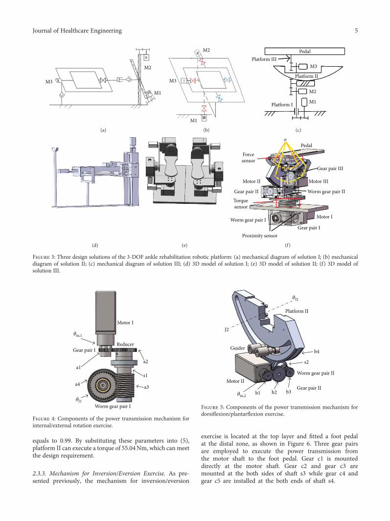
equals to 0.99. By substituting these parameters into (5),platform II can execute a torque of 55.04Nm, which canmeetthe design requirement.
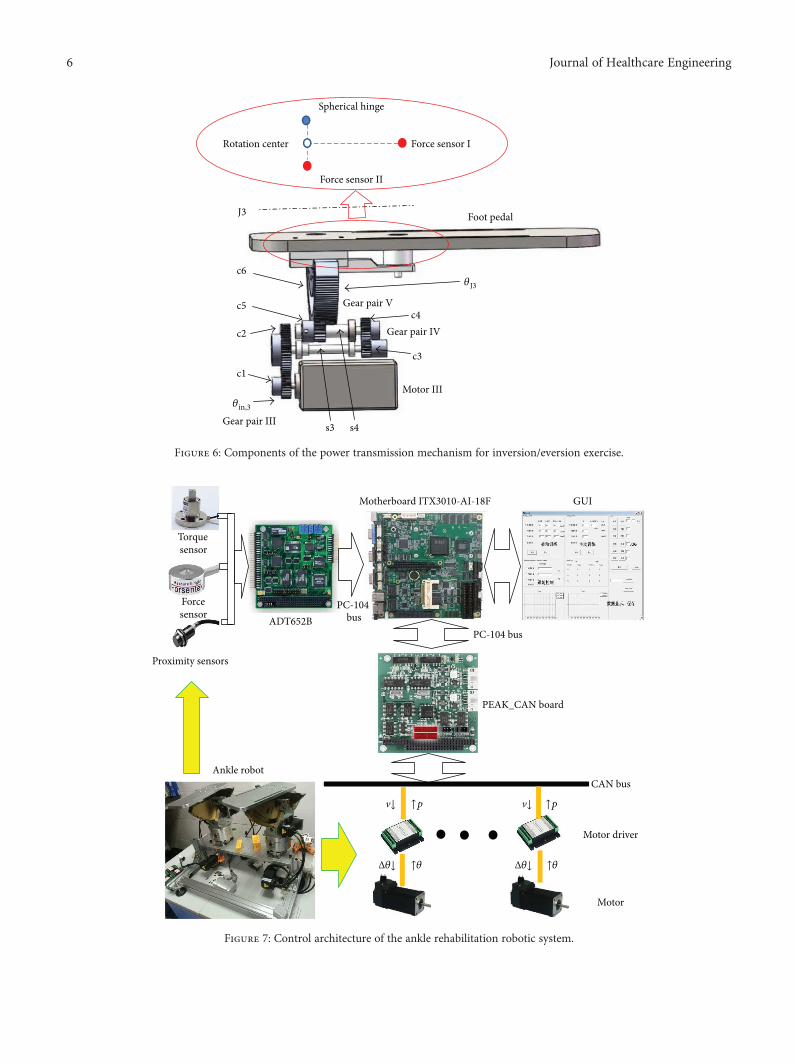
2.3.3. Mechanism for Inversion/Eversion Exercise. As pre-sented previously, the mechanism for inversion/eversion
exercise is located at the top layer and fitted a foot pedalat the distal zone, as shown in Figure 6. Three gear pairsare employed to execute the power transmission fromthe motor shaft to the foot pedal. Gear c1 is mounteddirectly at the motor shaft. Gear c2 and gear c3 aremounted at the both sides of shaft s3 while gear c4 andgear c5 are installed at the both ends of shaft s4.
M3
M1
M2
(a)
M1
M2
M3
(b)
Platform IIIPedal
M3
Platform II
M2
M1Platform I
(c)
(d) (e)
Pedalo
Proximity sensor
Forcesensor
Motor II
Gear pair II
Torquesensor
Worm gear pair IGear pair I
Motor I
Worm gear pair II
Motor III
Gear pair III
(f)
Figure 3: Three design solutions of the 3-DOF ankle rehabilitation robotic platform: (a) mechanical diagram of solution I; (b) mechanicaldiagram of solution II; (c) mechanical diagram of solution III; (d) 3D model of solution I; (e) 3D model of solution II; (f) 3D model ofsolution III.
Motor I
Gear pair IReducer
Worm gear pair I
a1a2
a3a4s1
𝜃in,1
𝜃J1
Figure 4: Components of the power transmission mechanism forinternal/external rotation exercise.
Motor IIGear pair II
Worm gear pair II
Platform II
Guider
b1 b2 b3
b4
s2
𝜃in,2
𝜃J2
J2
Figure 5: Components of the power transmission mechanism fordorsiflexion/plantarflexion exercise.
5Journal of Healthcare Engineering
Motor III
Gear pair III
Gear pair IV
Gear pair V
Foot pedal
c1
c2
c3
c4c5
c6
s3 s4
𝜃in,3
𝜃J3
J3
Force sensor I
Force sensor II
Spherical hinge
Rotation center
Figure 6: Components of the power transmission mechanism for inversion/eversion exercise.
CAN bus
PEAK_CAN board
Motor driver
Motor
PC-104 bus
Motherboard ITX3010-AI-18F GUI
ADT652B
Proximity sensors
v↓ v↓
PC-104 bus
Ankle robot
Torquesensor
Forcesensor
↑p ↑p
Δ𝜃↓ ↑𝜃 Δ𝜃↓ ↑𝜃
Figure 7: Control architecture of the ankle rehabilitation robotic system.
6 Journal of Healthcare Engineering
Gear c1, actuated by a brushless DC motor(MT8N42P06V2E), bites with gear c2 in gear pair III, and thesimilar configuration was constructed in gear pair IV and gearpair V. The equation bridging joint movement θJ3 to the rota-tion θin,3 can be expressed as follows:
θJ3 = θin,3Nc1,c2Nc3,c4Nc5,c6, 6
where Nc1,c2 = 2 2, Nb2,b3 = 1 5, and Nb3,b4 = 17 1. Based onthe known parameters, we can obtain that the robotic jointJ3 can achieve a maximum angular velocity of 319 degrees/s; the output torque of the robotic joint J3 can be described as
T3out = T3Nc1,c2Nc2,c3Nc3,c4 η32η24 , 7
where T3out is the output torque of motor III, T3 is the ratedtorque of motor III, η2 is the transmission efficiency of thecylindrical gear pair and equals to 0.98, and η4 is the trans-mission efficiency of the ball bearing and equals to 0.99. Bysubstituting the parameters into (7), the foot pedal canachieve 10.41Nm for inversion/eversion exercise.
Two force sensors (FL25-100 kg, ForsentekCo., Shenzhen,China) are mounted under the foot pedal, based on the leverprinciple; the torque generated for dorsiflexion/plantarflexionand inversion/eversion movements can be calculated by
T inv /ev = 2F2l1 + F1l1,Tdor /plantar = F1l2,
8
where T inv /ev and Tdor /plantar represent the rotationaltorques of inversion/eversion and dorsiflexion/plantarflex-ion, respectively. F1 and F2 denote the measured force onsensor I and sensor II, and l1 and l2 are the length of thecorresponding cantilevers.
2.4. Overview of the Control Architecture. For the ankle reha-bilitation robotic platform, six IBL3605A motor drivers(made by Techservo Co. Ltd., Shenzhen, China) are used todrive the two 3-DOF layer-stacking robotic platforms.Encodes embedded in the motors provide the current relativeangular position of each motor shaft, thus enabling a semi-closed loop position control. All the drivers communicatevia CAN bus with a PC-104-based personal computer (PC).TheC++ software that runs on the PCobtains control instruc-tions from the peripheral equipment (mouse, keyboard, andsensors) and sends the desired velocity of the motors to thecontrollers through a CAN-PC104 card (PEAK-SystemTech-nik, Germany). The relations between each submodule of thecontrol system are described in Figure 7.
As shown in Figure 7, the user sets the ankle exerciseparameters and chooses the exercise mode via GUI on thePC. By combining the sensing data and user input fromGUI, the motion amount of each joint can be calculated inthe PC and delivered to the corresponding motor throughCAN bus. The generated encoder data, internal/externalrotation torque (torque sensor), foot pressure (force sensor),and joint range limits (proximity sensor) will be sent back tothe controller as a compensation for the input.
Based on the designed ankle rehabilitation robotic plat-form, a healthy subject with no experience of using the robotwas selected to complete three trajectories on each exercisemode mentioned in Section 2.2. The user had 5min to famil-iarize himself with the operating characteristics of the robotsystem before executing the ankle exercises.
3. Results and Discussion
As introduced in Section 2, the ankle rehabilitation roboticplatform consists of two symmetric exercise mechanisms.The mechanical configuration allows patients to executethe affected ankle exercise only or the coordination train-ing on both feet. Three ankle exercise modes are designedto execute ankle rehabilitation corresponding to differentrehabilitation stages.
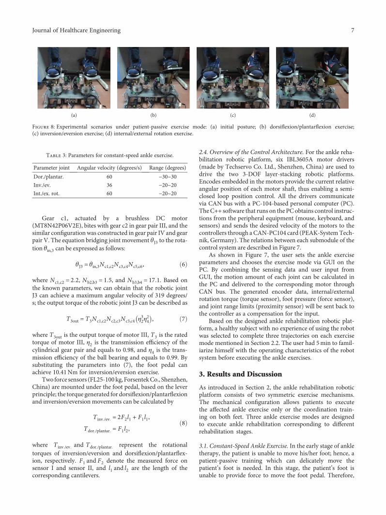
3.1. Constant-Speed Ankle Exercise. In the early stage of ankletherapy, the patient is unable to move his/her foot; hence, apatient-passive training which can delicately move thepatient’s foot is needed. In this stage, the patient’s foot isunable to provide force to move the foot pedal. Therefore,
(a) (b) (c) (d)
Figure 8: Experimental scenarios under patient-passive exercise mode: (a) initial posture; (b) dorsiflexion/plantarflexion exercise;(c) inversion/eversion exercise; (d) internal/external rotation exercise.
Table 3: Parameters for constant-speed ankle exercise.
Parameter joint Angular velocity (degrees/s) Range (degrees)
Dor./plantar. 60 −30~30Inv./ev. 36 −20~20Int./ex. rot. 60 −20~20
7Journal of Healthcare Engineering
the objective of this rehabilitation stage is to exercise theaffected muscles to avoid muscle atrophy.
In order to avoid exercise injury, the robot shouldprovide moderate exercise with a constant speed in the earlystage. The experimental scenario is shown in Figure 8. The
user sets the exercise velocity and angle of joint motion viaGUI (parameters are listed in Table 3).
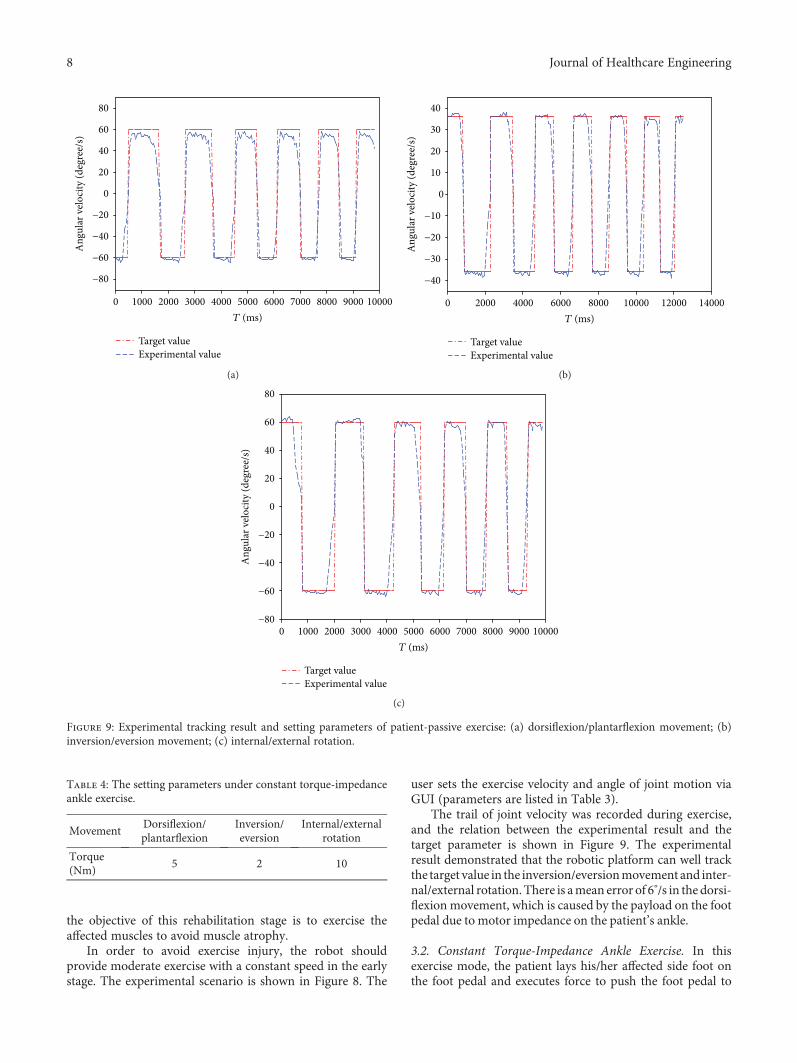
The trail of joint velocity was recorded during exercise,and the relation between the experimental result and thetarget parameter is shown in Figure 9. The experimentalresult demonstrated that the robotic platform can well trackthe target value in the inversion/eversionmovement and inter-nal/external rotation. There is amean error of 6°/s in the dorsi-flexion movement, which is caused by the payload on the footpedal due to motor impedance on the patient’s ankle.
3.2. Constant Torque-Impedance Ankle Exercise. In thisexercise mode, the patient lays his/her affected side foot onthe foot pedal and executes force to push the foot pedal to
1000 2000 3000 4000 5000 6000 7000 8000 9000 10000T (ms)
0
Target valueExperimental value
−80
−60
−40
−20
0
20
40
60
80
Ang
ular
vel
ocity
(deg
ree/
s)
(a)
2000 4000 6000 8000 10000 12000 14000T (ms)
0
Target valueExperimental value
−40
−30
−20
−10
0
10
20
30
40
Ang
ular
vel
ocity
(deg
ree/
s)
(b)
0 1000 2000 3000 4000 5000 6000 7000 8000 9000 10000T (ms)
Target valueExperimental value
−80
−60
−40
−20
0
20
40
60
80
Ang
ular
vel
ocity
(deg
ree/
s)
(c)
Figure 9: Experimental tracking result and setting parameters of patient-passive exercise: (a) dorsiflexion/plantarflexion movement; (b)inversion/eversion movement; (c) internal/external rotation.
Table 4: The setting parameters under constant torque-impedanceankle exercise.
MovementDorsiflexion/plantarflexion
Inversion/eversion
Internal/externalrotation
Torque(Nm)
5 2 10
8 Journal of Healthcare Engineering
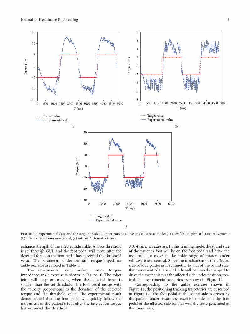
enhance strength of the affected side ankle. A force thresholdis set through GUI, and the foot pedal will move after thedetected force on the foot pedal has exceeded the thresholdvalue. The parameters under constant torque-impedanceankle exercise are noted in Table 4.
The experimental result under constant torque-impedance ankle exercise is shown in Figure 10. The robotjoint will keep on moving when the detected force issmaller than the set threshold. The foot pedal moves withthe velocity proportional to the deviation of the detectedtorque and the threshold value. The experimental resultdemonstrated that the foot pedal will quickly follow themovement of the patient’s foot after the interaction torquehas exceeded the threshold.
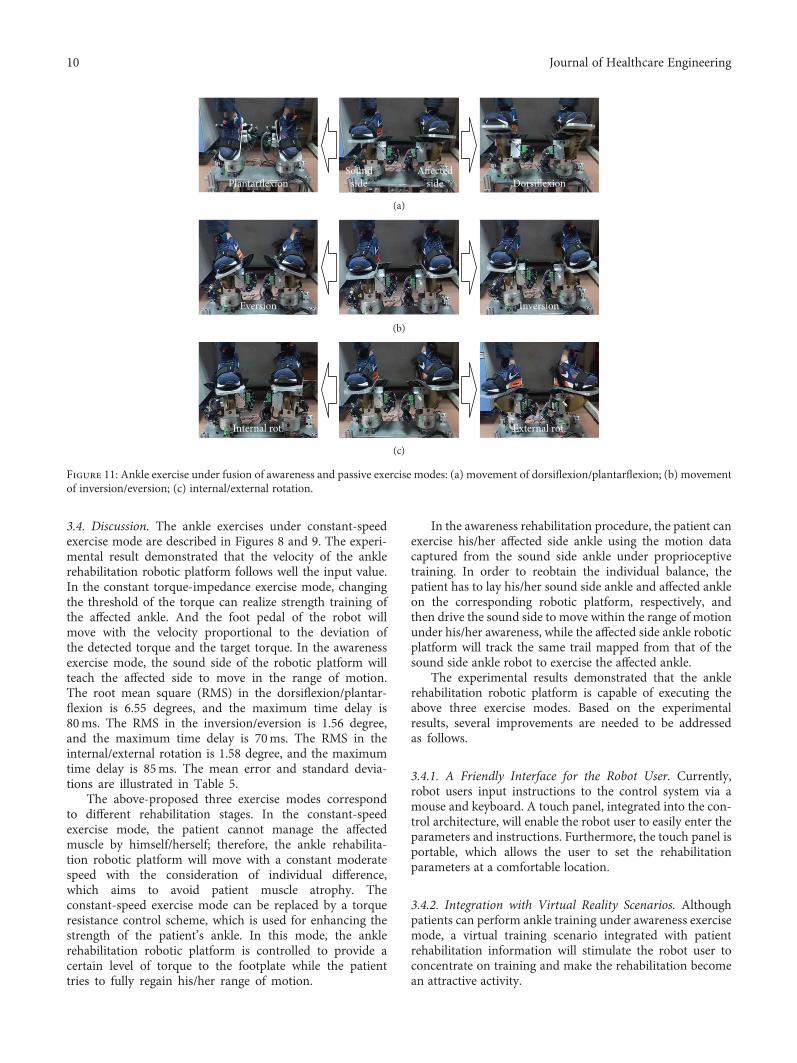
3.3. Awareness Exercise. In this training mode, the sound sideof the patient’s foot will lie on the foot pedal and drive thefoot pedal to move in the ankle range of motion underself-awareness control. Since the mechanism of the affectedside robotic platform is symmetric to that of the sound side,the movement of the sound side will be directly mapped todrive the mechanism at the affected side under position con-trol. The experimental scenarios are shown in Figure 11.
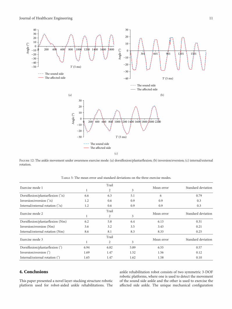
Corresponding to the ankle exercise shown inFigure 11, the positioning tracking trajectories are describedin Figure 12. The foot pedal at the sound side is driven bythe patient under awareness exercise mode, and the footpedal at the affected side follows well the trace generated atthe sound side.
500 1000 1500 2000 2500 3000 3500 4000 4500 5000T (ms)
0
Target valueExperimental value
−15
−10
−5
0
5
10
15
Torq
ue (N
m)
(a)
0 500 1000 1500 2000 2500 3000 3500 4000 4500 5000T (ms)
Target valueExperimental value
−8
−6
−4
−2
0
2
4
6
8
Torq
ue (N
m)
(b)
0 1000 2000 3000 4000 5000 6000T (ms)
Target valueExperimental value
−30
−20
−10
0
10
20
30
Torq
ue (N
m)
(c)
Figure 10: Experimental data and the target threshold under patient-active ankle exercise mode: (a) dorsiflexion/plantarflexion movement;(b) inversion/eversion movement; (c) internal/external rotation.
9Journal of Healthcare Engineering
3.4. Discussion. The ankle exercises under constant-speedexercise mode are described in Figures 8 and 9. The experi-mental result demonstrated that the velocity of the anklerehabilitation robotic platform follows well the input value.In the constant torque-impedance exercise mode, changingthe threshold of the torque can realize strength training ofthe affected ankle. And the foot pedal of the robot willmove with the velocity proportional to the deviation ofthe detected torque and the target torque. In the awarenessexercise mode, the sound side of the robotic platform willteach the affected side to move in the range of motion.The root mean square (RMS) in the dorsiflexion/plantar-flexion is 6.55 degrees, and the maximum time delay is80ms. The RMS in the inversion/eversion is 1.56 degree,and the maximum time delay is 70ms. The RMS in theinternal/external rotation is 1.58 degree, and the maximumtime delay is 85ms. The mean error and standard devia-tions are illustrated in Table 5.
The above-proposed three exercise modes correspondto different rehabilitation stages. In the constant-speedexercise mode, the patient cannot manage the affectedmuscle by himself/herself; therefore, the ankle rehabilita-tion robotic platform will move with a constant moderatespeed with the consideration of individual difference,which aims to avoid patient muscle atrophy. Theconstant-speed exercise mode can be replaced by a torqueresistance control scheme, which is used for enhancing thestrength of the patient’s ankle. In this mode, the anklerehabilitation robotic platform is controlled to provide acertain level of torque to the footplate while the patienttries to fully regain his/her range of motion.
In the awareness rehabilitation procedure, the patient canexercise his/her affected side ankle using the motion datacaptured from the sound side ankle under proprioceptivetraining. In order to reobtain the individual balance, thepatient has to lay his/her sound side ankle and affected ankleon the corresponding robotic platform, respectively, andthen drive the sound side to move within the range of motionunder his/her awareness, while the affected side ankle roboticplatform will track the same trail mapped from that of thesound side ankle robot to exercise the affected ankle.
The experimental results demonstrated that the anklerehabilitation robotic platform is capable of executing theabove three exercise modes. Based on the experimentalresults, several improvements are needed to be addressedas follows.
3.4.1. A Friendly Interface for the Robot User. Currently,robot users input instructions to the control system via amouse and keyboard. A touch panel, integrated into the con-trol architecture, will enable the robot user to easily enter theparameters and instructions. Furthermore, the touch panel isportable, which allows the user to set the rehabilitationparameters at a comfortable location.
3.4.2. Integration with Virtual Reality Scenarios. Althoughpatients can perform ankle training under awareness exercisemode, a virtual training scenario integrated with patientrehabilitation information will stimulate the robot user toconcentrate on training and make the rehabilitation becomean attractive activity.
DorsiflexionPlantarflexionSound
sideAffected
side
(a)
InversionEversion
(b)
External rot.Internal rot.
(c)
Figure 11: Ankle exercise under fusion of awareness and passive exercise modes: (a) movement of dorsiflexion/plantarflexion; (b) movementof inversion/eversion; (c) internal/external rotation.
10 Journal of Healthcare Engineering
4. Conclusions
This paper presented a novel layer-stacking structure roboticplatform used for robot-aided ankle rehabilitations. The
ankle rehabilitation robot consists of two symmetric 3-DOFrobotic platforms, where one is used to detect the movementof the sound side ankle and the other is used to exercise theaffected side ankle. The unique mechanical configuration
40302010
0−10−20−30−40−50
Ang
le (°
)
T (5 ms)
0 200 400 600 800 1000 1200 1400 1600 1800
�e sound side�e affected side
(a)
30
20
10
0
−10
−20
−30
−40
Ang
le (°
)
T (5 ms)
1 301 601 901 1201 1501
�e sound side�e affected side
(b)
30
20
10
0
−10
−20
−30
Ang
le (°
)
T (5 ms)
0 200 400 600 800 1000 1200 1400 1600 1800 2000 2200
�e sound side�e affected side
(c)
Figure 12: The ankle movement under awareness exercise mode: (a) dorsiflexion/plantarflexion; (b) inversion/eversion; (c) internal/externalrotation.
Table 5: The mean error and standard deviations on the three exercise modes.
Exercise mode 1Trail
Mean error Standard deviation1 2 3
Dorsiflexion/plantarflexion (°/s) 6.6 6.3 5.1 6 0.79
Inversion/eversion (°/s) 1.2 0.6 0.9 0.9 0.3
Internal/external rotation (°/s) 1.2 0.6 0.9 0.9 0.3
Exercise mode 2Trail
Mean error Standard deviation1 2 3
Dorsiflexion/plantarflexion (Nm) 6.2 5.8 6.4 6.13 0.31
Inversion/eversion (Nm) 3.6 3.2 3.5 3.43 0.21
Internal/external rotation (Nm) 8.6 8.1 8.3 8.33 0.25
Exercise mode 3Trail
Mean error Standard deviation1 2 3
Dorsiflexion/plantarflexion (°) 6.94 6.82 5.89 6.55 0.57
Inversion/eversion (°) 1.69 1.47 1.52 1.56 0.12
Internal/external rotation (°) 1.65 1.47 1.62 1.58 0.10
11Journal of Healthcare Engineering
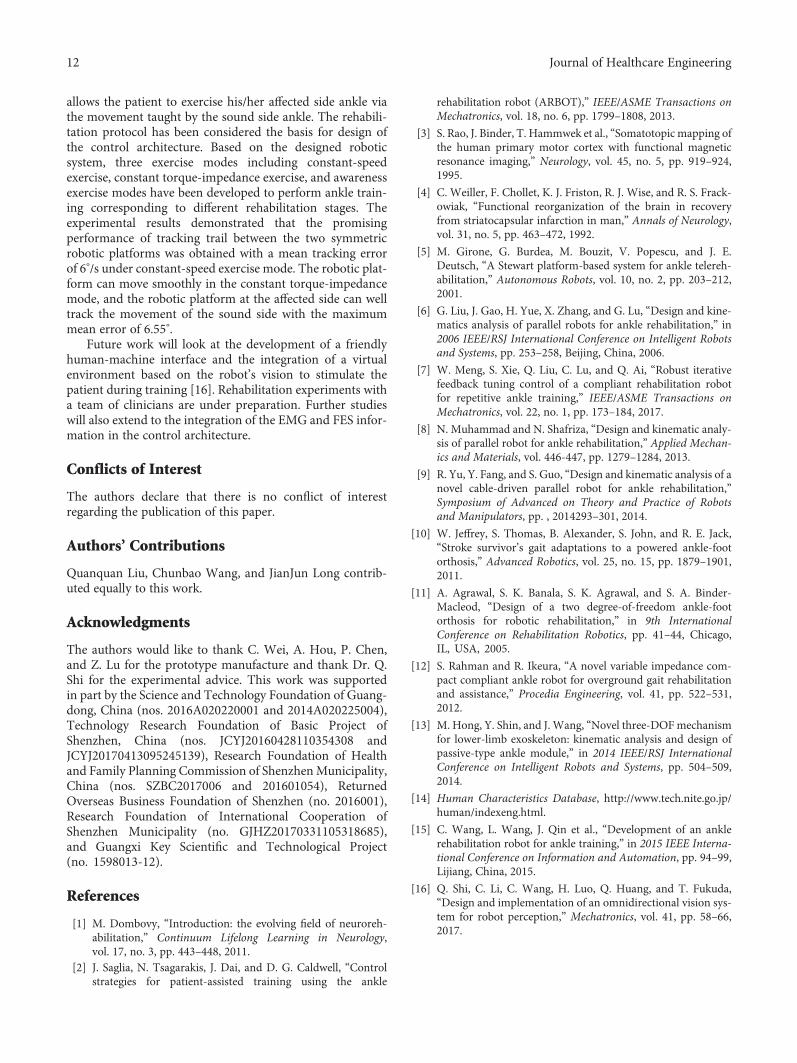
allows the patient to exercise his/her affected side ankle viathe movement taught by the sound side ankle. The rehabili-tation protocol has been considered the basis for design ofthe control architecture. Based on the designed roboticsystem, three exercise modes including constant-speedexercise, constant torque-impedance exercise, and awarenessexercise modes have been developed to perform ankle train-ing corresponding to different rehabilitation stages. Theexperimental results demonstrated that the promisingperformance of tracking trail between the two symmetricrobotic platforms was obtained with a mean tracking errorof 6°/s under constant-speed exercise mode. The robotic plat-form can move smoothly in the constant torque-impedancemode, and the robotic platform at the affected side can welltrack the movement of the sound side with the maximummean error of 6.55°.
Future work will look at the development of a friendlyhuman-machine interface and the integration of a virtualenvironment based on the robot’s vision to stimulate thepatient during training [16]. Rehabilitation experiments witha team of clinicians are under preparation. Further studieswill also extend to the integration of the EMG and FES infor-mation in the control architecture.
Conflicts of Interest
The authors declare that there is no conflict of interestregarding the publication of this paper.
Authors’ Contributions
Quanquan Liu, Chunbao Wang, and JianJun Long contrib-uted equally to this work.
Acknowledgments
The authors would like to thank C. Wei, A. Hou, P. Chen,and Z. Lu for the prototype manufacture and thank Dr. Q.Shi for the experimental advice. This work was supportedin part by the Science and Technology Foundation of Guang-dong, China (nos. 2016A020220001 and 2014A020225004),Technology Research Foundation of Basic Project ofShenzhen, China (nos. JCYJ20160428110354308 andJCYJ20170413095245139), Research Foundation of Healthand Family Planning Commission of ShenzhenMunicipality,China (nos. SZBC2017006 and 201601054), ReturnedOverseas Business Foundation of Shenzhen (no. 2016001),Research Foundation of International Cooperation ofShenzhen Municipality (no. GJHZ20170331105318685),and Guangxi Key Scientific and Technological Project(no. 1598013-12).
References
[1] M. Dombovy, “Introduction: the evolving field of neuroreh-abilitation,” Continuum Lifelong Learning in Neurology,vol. 17, no. 3, pp. 443–448, 2011.
[2] J. Saglia, N. Tsagarakis, J. Dai, and D. G. Caldwell, “Controlstrategies for patient-assisted training using the ankle
rehabilitation robot (ARBOT),” IEEE/ASME Transactions onMechatronics, vol. 18, no. 6, pp. 1799–1808, 2013.
[3] S. Rao, J. Binder, T. Hammwek et al., “Somatotopic mapping ofthe human primary motor cortex with functional magneticresonance imaging,” Neurology, vol. 45, no. 5, pp. 919–924,1995.
[4] C. Weiller, F. Chollet, K. J. Friston, R. J. Wise, and R. S. Frack-owiak, “Functional reorganization of the brain in recoveryfrom striatocapsular infarction in man,” Annals of Neurology,vol. 31, no. 5, pp. 463–472, 1992.
[5] M. Girone, G. Burdea, M. Bouzit, V. Popescu, and J. E.Deutsch, “A Stewart platform-based system for ankle telereh-abilitation,” Autonomous Robots, vol. 10, no. 2, pp. 203–212,2001.
[6] G. Liu, J. Gao, H. Yue, X. Zhang, and G. Lu, “Design and kine-matics analysis of parallel robots for ankle rehabilitation,” in2006 IEEE/RSJ International Conference on Intelligent Robotsand Systems, pp. 253–258, Beijing, China, 2006.
[7] W. Meng, S. Xie, Q. Liu, C. Lu, and Q. Ai, “Robust iterativefeedback tuning control of a compliant rehabilitation robotfor repetitive ankle training,” IEEE/ASME Transactions onMechatronics, vol. 22, no. 1, pp. 173–184, 2017.
[8] N. Muhammad and N. Shafriza, “Design and kinematic analy-sis of parallel robot for ankle rehabilitation,” Applied Mechan-ics and Materials, vol. 446-447, pp. 1279–1284, 2013.
[9] R. Yu, Y. Fang, and S. Guo, “Design and kinematic analysis of anovel cable-driven parallel robot for ankle rehabilitation,”Symposium of Advanced on Theory and Practice of Robotsand Manipulators, pp. , 2014293–301, 2014.
[10] W. Jeffrey, S. Thomas, B. Alexander, S. John, and R. E. Jack,“Stroke survivor’s gait adaptations to a powered ankle-footorthosis,” Advanced Robotics, vol. 25, no. 15, pp. 1879–1901,2011.
[11] A. Agrawal, S. K. Banala, S. K. Agrawal, and S. A. Binder-Macleod, “Design of a two degree-of-freedom ankle-footorthosis for robotic rehabilitation,” in 9th InternationalConference on Rehabilitation Robotics, pp. 41–44, Chicago,IL, USA, 2005.
[12] S. Rahman and R. Ikeura, “A novel variable impedance com-pact compliant ankle robot for overground gait rehabilitationand assistance,” Procedia Engineering, vol. 41, pp. 522–531,2012.
[13] M. Hong, Y. Shin, and J. Wang, “Novel three-DOFmechanismfor lower-limb exoskeleton: kinematic analysis and design ofpassive-type ankle module,” in 2014 IEEE/RSJ InternationalConference on Intelligent Robots and Systems, pp. 504–509,2014.
[14] Human Characteristics Database, http://www.tech.nite.go.jp/human/indexeng.html.
[15] C. Wang, L. Wang, J. Qin et al., “Development of an anklerehabilitation robot for ankle training,” in 2015 IEEE Interna-tional Conference on Information and Automation, pp. 94–99,Lijiang, China, 2015.
[16] Q. Shi, C. Li, C. Wang, H. Luo, Q. Huang, and T. Fukuda,“Design and implementation of an omnidirectional vision sys-tem for robot perception,” Mechatronics, vol. 41, pp. 58–66,2017.
12 Journal of Healthcare Engineering

International Journal of
AerospaceEngineeringHindawiwww.hindawi.com Volume 2018
RoboticsJournal of
Hindawiwww.hindawi.com Volume 2018
Hindawiwww.hindawi.com Volume 2018
Active and Passive Electronic Components
VLSI Design
Hindawiwww.hindawi.com Volume 2018
Hindawiwww.hindawi.com Volume 2018
Shock and Vibration
Hindawiwww.hindawi.com Volume 2018
Civil EngineeringAdvances in
Acoustics and VibrationAdvances in
Hindawiwww.hindawi.com Volume 2018
Hindawiwww.hindawi.com Volume 2018
Electrical and Computer Engineering
Journal of
Advances inOptoElectronics
Hindawiwww.hindawi.com
Volume 2018
Hindawi Publishing Corporation http://www.hindawi.com Volume 2013Hindawiwww.hindawi.com
The Scientific World Journal
Volume 2018
Control Scienceand Engineering
Journal of
Hindawiwww.hindawi.com Volume 2018
Hindawiwww.hindawi.com
Journal ofEngineeringVolume 2018
SensorsJournal of
Hindawiwww.hindawi.com Volume 2018
International Journal of
RotatingMachinery
Hindawiwww.hindawi.com Volume 2018
Modelling &Simulationin EngineeringHindawiwww.hindawi.com Volume 2018
Hindawiwww.hindawi.com Volume 2018
Chemical EngineeringInternational Journal of Antennas and
Propagation
International Journal of
Hindawiwww.hindawi.com Volume 2018
Hindawiwww.hindawi.com Volume 2018
Navigation and Observation
International Journal of
Hindawi
www.hindawi.com Volume 2018
Advances in
Multimedia
Submit your manuscripts atwww.hindawi.com