Embed Size (px)
Citation preview
165 © 2014 ISIJ
ISIJ International, Vol. 54 (2014), No. 1, pp. 165–170
Development of a Rolling Chatter Model Considering Unsteady Lubrication
Ali HEIDARI,* Mohammad Reza FOROUZAN and Saleh AKBARZADEH
Department of Mechanical Engineering, Isfahan University of Technology, Isfahan, 84156-83111 Iran.
(Received on June 9, 2013; accepted on August 26, 2013)
Chatter, limiting the rolling speed for thin steel strips, has been identified as a serious limitation inincreasing the efficiency of the cold rolling process. Many experimental investigations have led to thepoint that lubrication is one of the effective factors causing chatter. In this article, a new chatter model ofthe cold strip rolling with consideration of unsteady lubrication is proposed. The limiting shear stress con-cept and the variation of the lubricant viscosity with pressure are considered in this model. The results ofthe simulation are verified by comparing to experimental data. Also, a parametric study on the effect ofsome of the major parameters of rolling lubricant on the chatter critical speed is conducted. The resultsshow that under the operating conditions of this paper, the limiting shear stress is an effective parameter.
KEY WORDS: rolling; vibration; chatter; unsteady lubrication; experiment.
1. Introduction
Chatter is the most destructive vibration problem for thinsteel strips in the cold rolling processes. Rolling chatter hasthree different types: third octave, fifth octave, and torsionalchatter.1) The first is the most important type because it canlead to large gauge fluctuations, surface finish imperfec-tions, and damage to mills.2) Also the lubricant flowbetween the work roll and the strip surface becomesextremely unsteady as a result of chatter. Many researchershave mentioned that lubrication is one of the basic factorsincurring chatter.3–6) Due to the complexity of the problem,however, most of them have used simple friction models intheir analysis,7–10) and only very few researches havedescribed how chatter occurs through unsteady lubricationphenomenon.
Yarita et al.3) concluded from their practical investiga-tions that chatter arises from impaired lubrication. They sug-gested that lubricant film strength, emulsion stability, andparticle size distribution should be taken into considerationin selecting the rolling lubricants, and also the use of alubricant with good lubricity successfully prevent chatter.Johnson and Qi11,12) and Chen et al.13,14) considered frictionat the roll-strip interface as a function of relative velocitybetween the rolls and strip. Their study shows the impor-tance of friction in chatter predictions.
Tung15) developed an unsteady lubrication model forvibrations in cold rolling. Kimura et al.4) discovered theexistence of an optimum range for friction coefficient inwhich the vibrations are damped and the rolling mill is sta-ble despite the disturbances. Also, they showed that withincreasing the rolling speed, the rolling mill tends to chatter.
Yun et al.16–19) developed a fundamental understanding ofchatter in rolling. Based on a constant friction factor, theypresented a suitable dynamic model for studying chatter. Huet al.2,20–23) expanded Yan et al.’s work and pointed out thatthere are four principle mechanisms for third octave chatter:negative damping, mode coupling, regenerative, and modelmatching. They expressed that an appropriate friction modelis necessary to perform accurate chatter simulation.
Meehan7) investigated mode shapes and natural frequen-cies of a 4-high stand. It was seen from his research thatthird octave chatter and fifth octave chatter were verticallysymmetrical about the stand pass line. Yang et al.8) built achatter model for cold rolling including the hydraulic servosystem model. Also a mathematical model containing thedriving system was offered by Kim et al.9,24)
Wilson25) has defined four main lubrication regimes: thethick film and thin film regime (usually referred to as thefull film regime), the mixed regime and the boundaryregime. Most of models which considered lubrication havebeen developed under the assumption of steady flow oflubricant.26–28) This assumption, however, is not appropriatefor studying chatter.
In this paper, a new chatter model for the cold rolling pro-cess under the unsteady lubrication is presented. In order toverify the proposed model, experimental results obtainedfrom the cold strip tandem mill unit of Mobarakeh SteelCompany (MSC) are used. Based on this model, effect ofrolling lubricant parameters such as the rolling lubricant vis-cosity, the viscosity-pressure coefficient, and the limitingshear stress on chatter critical speed is studied.
2. Methodology
Rolling chatter is discussed as a consequence of interac-tions between the rolling process and the mill structure.
* Corresponding author: E-mail: [email protected]: http://dx.doi.org/10.2355/isijinternational.54.165
© 2014 ISIJ 166
ISIJ International, Vol. 54 (2014), No. 1
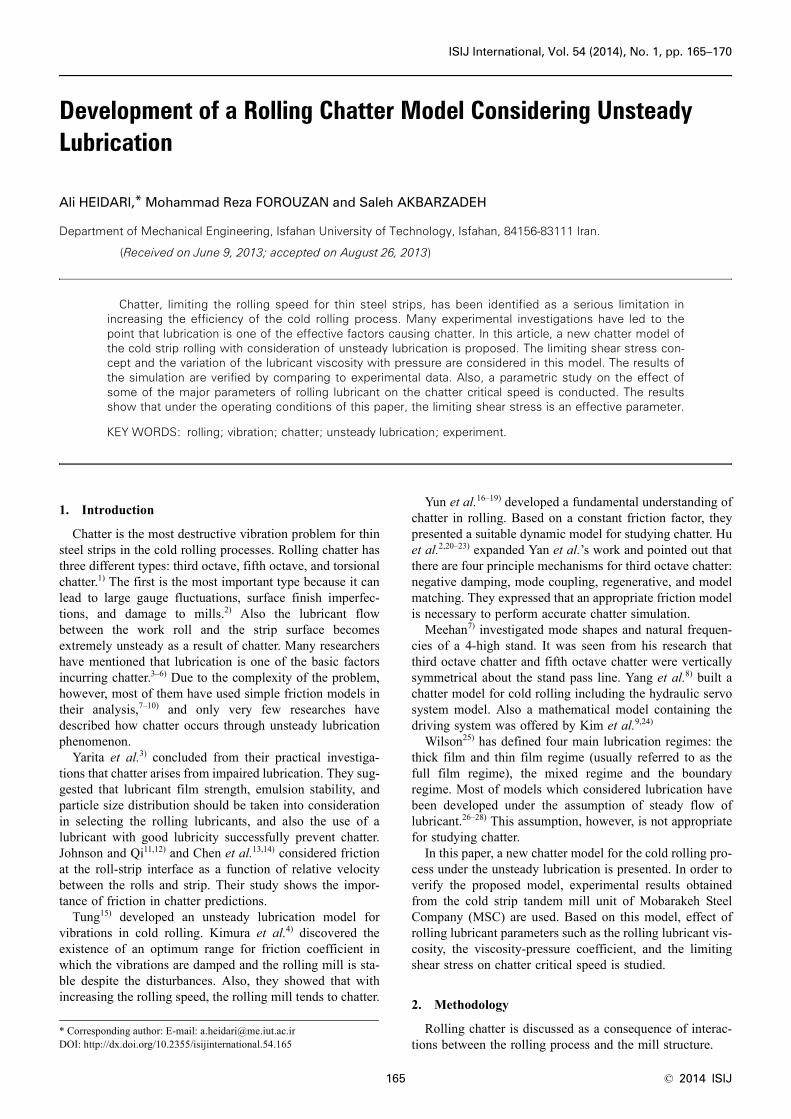
2.1. Rolling Process ModelIn this research, the lubrication regime is assumed to be
the full film. Figure 1 illustrates the coordinate system andgeometry of the rolling process. The roll bite is divided intoinlet, work and outlet zone. The first zone is where the lubri-cant pressure increases from the atmospheric pressure to thepressure required incurring strip plastic deformation. Thesecond zone is where the rolling force and torque are gen-erated. The variation of pressure in the last zone is reverseof that in the first zone. The lubricant pressure in the firstand last zone only cause strip elastic deformation.
2.1.1. Inlet Zone AnalysisAs the first step in the rolling process model, an inlet zone
analysis should be developed. The key output from thisanalysis is the inlet film thickness (h0(t)).
The hydrodynamic pressure causes the separationbetween the strip and roll. This pressure (p), built up bywedge and squeeze action, is obtained from the Reynoldsequation:
................. (1)
Where x' = x – x1, x1 is position of the boundary betweenthe inlet and work zone, h1 is the lubricant film thickness inthe inlet zone, η is the lubricant viscosity, t is the time and
is the mean value of strip speed at entry and roll periph-eral velocity. Since the lubricant viscosity depends on thepressure, the Barus equation29) is used to calculate the effec-tive viscosity:
................................. (2)
In which η0 is viscosity at the atmospheric pressure and αis the viscosity-pressure coefficient.
The boundary conditions in the inlet zone are:
................ (3)
In the above equation, σ k is the yield stress in the planestrain condition and σx,1 is the strip tensile stress at entry.Due to high ratio of strip width-to-strip thickness, it can beassumed that the rolling process operates in the plane straincondition.
In each time step increment, Eq. (1) is solved by applyingthe boundary conditions in order to determine the inlet film
thickness (h0(t)). The inlet film thickness shows the amountof the oil input into the work zone.
2.1.2. Work Zone AnalysisHaving determined the variation of inlet film thickness
from the inlet zone analysis, the work zone can now be ana-lyzed. The output of this analysis is the work zone filmthickness distribution (h(x, t)) which can be obtained fromthe continuity equation in fluid mechanics:
............................... (4)
Where vr is the roll peripheral velocity and u1 is the stripspeed at entry.
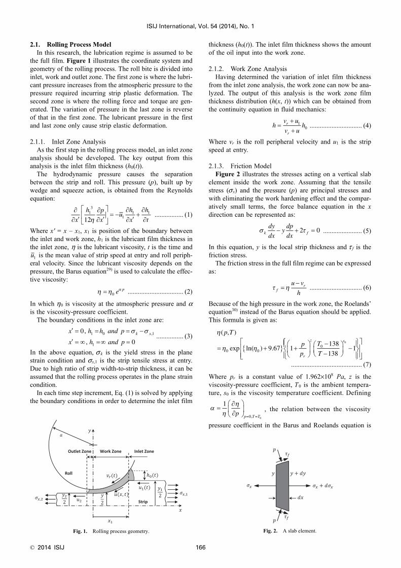
2.1.3. Friction ModelFigure 2 illustrates the stresses acting on a vertical slab
element inside the work zone. Assuming that the tensilestress (σ x) and the pressure (p) are principal stresses andwith eliminating the work hardening effect and the compar-atively small terms, the force balance equation in the xdirection can be represented as:
....................... (5)
In this equation, y is the local strip thickness and τ f is thefriction stress.
The friction stress in the full film regime can be expressedas:
............................... (6)
Because of the high pressure in the work zone, the Roelands’equation30) instead of the Barus equation should be applied.This formula is given as:
.......................................... (7)
Where pr is a constant value of 1.962×10⁸ Pa, z is theviscosity-pressure coefficient, T0 is the ambient tempera-ture, s0 is the viscosity temperature coefficient. Defining
, the relation between the viscosity
pressure coefficient in the Barus and Roelands equation is
Fig. 1. Rolling process geometry.
∂∂ ′
∂∂ ′
⎡
⎣⎢
⎤
⎦⎥ = −
∂∂ ′
+∂∂x
h p
xu
h
x
h
t13
11 1
12η
u1
η η α= 0 ep
′ = = = −
′ = ∞ =∞ =
x h h and p
x h and pk x0
01 0 1
1
,
,,σ σ
Fig. 2. A slab element.
hv u
v uhr
r
=++
10
σ τk f
dy
dxydp
dx− + =2 0
τ ηfru v
h=
−
η
η η
( , )
exp ln( ) .
p T
p
p
T
Tr
z s
= +{ } +⎛
⎝⎜
⎞
⎠⎟
−−
⎛⎝⎜
⎞⎠⎟ −0 0
09 67 1138
1381
0⎧⎧⎨⎪
⎩⎪
⎫⎬⎪
⎭⎪
⎡
⎣⎢⎢
⎤
⎦⎥⎥
αη
η=
∂∂
⎛
⎝⎜
⎞
⎠⎟
= =
1
0 0p
p T T,
ISIJ International, Vol. 54 (2014), No. 1
167 © 2014 ISIJ
given by:
..................... (8)
Meanwhile, the limiting shear stress (τL) concept is used inthis study, which means that a viscoplastic behavior isassumed for the lubricant.31,32) Thus, when the friction stressexceeds the limiting shear stress, the friction stress is setequal to the limiting shear stress.
In the friction model, the pressure in the work zone iscomputed based on the Eqs. (5) to (8) and the film thicknessdistribution obtained from the work zone analysis. Integrat-ing the pressure distribution gives an estimation of the roll-ing force. Also, considering the mass conservation and giventhe fact that the strip speed at neutral point is equal to theroll peripheral velocity, the strip speed at entry and exit havebeen obtained.33,34)
2.2. Mill Structural ModelThe focus of this research is on the third octave chatter,
which is symmetric with respect to the center-plane of thestrip and is only a function of the vertical vibration.7) Byneglecting the horizontal and torsional vibration, a uni-directional structure model is used as shown in Fig. 3. Thismodel was used by many other researchers.7,12,34)
The relationship between the displacements of the centerof the work roll (yw) and the center of the backup roll (yb)and the rolling force variation (dfy) can be expressed by twosecond order differential equations:
.......................................... (9)
The subscripts ‘w’ and ‘b’ signify the work and backup rollrespectively. M is the roll mass, C is the damping
coefficient, K is the spring constant and w is the strip width.It is worth mentioning that the displacement of work rollcenter and the strip thickness variation at exit (dy2) can berelated as yw = dy2/2.
2.3. Chatter ModelThe rolling vibration model is achieved by combining the
rolling process model with the mill structural model. Figure4 shows the chatter model for a single stand.
The variation of strip tensile stress at entry and exit ofstand is proportional to the integral of the differencebetween the variations of the exit speed of a stand and theentry speed of next stand.
............. (10)
...............(11)
Where i is indicative of the (i)’ th stand, E is the Young’smodulus of the strip and Li is the distance between Stands iand i+1.
The inputs of the rolling process model are the strip thick-ness at entry, the strip tensile stress at entry and exit. Theoutputs of that are the strip thickness at exit, the strip speedat entry and exit and the rolling force. The output speeds areused to calculate the strip tensile stress. The dynamic rollingforce enters to the mill structural model. It leads to variationof the roll gap spacing and this variation enters to the pro-cess model. So the relationship between the rolling processand the mill structural model continues.
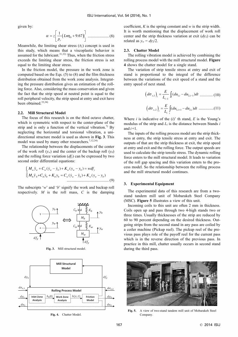
3. Experimental Equipment
The experimental data of this research are from a two-stand tandem mill unit of Mobarakeh Steel Company(MSC). Figure 5 illustrates a view of this unit.
Incoming coils to this unit are often 2 mm in thickness.Coils open up and pass through two 4-high stands two orthree times. Usually thicknesses of the strip are reduced by60 to 90 percent depending on the desired thickness. Out-going strips from the second stand in any pass are coiled bya coiler machine (Pickup reel). The pickup reel of the pre-vious pass plays role of the payoff reel for the current passwhich is in the reverse direction of the previous pass. Inpractice in this mill, chatter usually occurs in second standduring the third pass.Fig. 3. Mill structural model.
Fig. 4. Chatter Model.
α η= +( )⎡
⎣⎢
⎤
⎦⎥z
pLn
r
19 670 .
M y C y y K y y wdf
M y C y K y C y
w w w w b w w b y
b b b b b b w w
+ − + − =
+ + = −
( ) ( )
( y K y yb w w b) ( )+ −
⎧⎨⎪
⎩⎪
Fig. 5. A view of two-stand tandem mill unit of Mobarakeh SteelCompany.
dE
Ldu du dtx i
ii it
σ , , ,( )11
1 2 1( ) = −−
−∫
dE
Ldu du dtx i
ii i
t
σ , , ,( )2 1 1 2( ) = −+∫
© 2014 ISIJ 168
ISIJ International, Vol. 54 (2014), No. 1
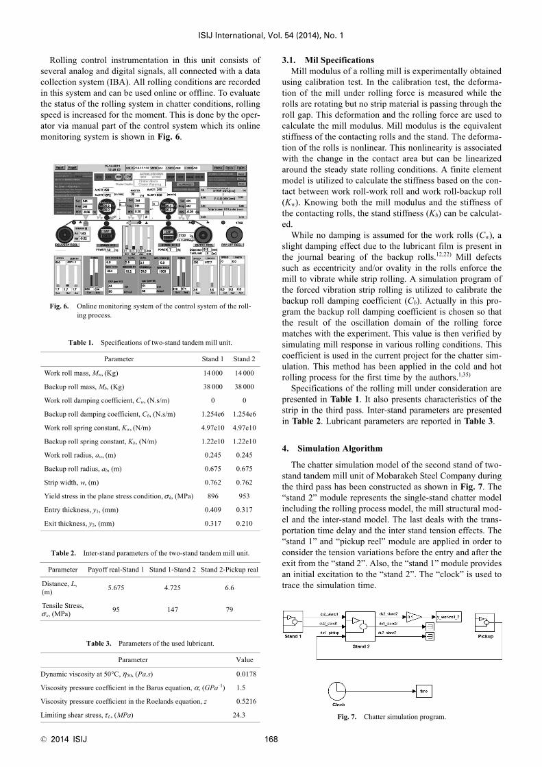
Rolling control instrumentation in this unit consists ofseveral analog and digital signals, all connected with a datacollection system (IBA). All rolling conditions are recordedin this system and can be used online or offline. To evaluatethe status of the rolling system in chatter conditions, rollingspeed is increased for the moment. This is done by the oper-ator via manual part of the control system which its onlinemonitoring system is shown in Fig. 6.
3.1. Mil SpecificationsMill modulus of a rolling mill is experimentally obtained
using calibration test. In the calibration test, the deforma-tion of the mill under rolling force is measured while therolls are rotating but no strip material is passing through theroll gap. This deformation and the rolling force are used tocalculate the mill modulus. Mill modulus is the equivalentstiffness of the contacting rolls and the stand. The deforma-tion of the rolls is nonlinear. This nonlinearity is associatedwith the change in the contact area but can be linearizedaround the steady state rolling conditions. A finite elementmodel is utilized to calculate the stiffness based on the con-tact between work roll-work roll and work roll-backup roll(Kw). Knowing both the mill modulus and the stiffness ofthe contacting rolls, the stand stiffness (Kb) can be calculat-ed.
While no damping is assumed for the work rolls (Cw), aslight damping effect due to the lubricant film is present inthe journal bearing of the backup rolls.12,22) Mill defectssuch as eccentricity and/or ovality in the rolls enforce themill to vibrate while strip rolling. A simulation program ofthe forced vibration strip rolling is utilized to calibrate thebackup roll damping coefficient (Cb). Actually in this pro-gram the backup roll damping coefficient is chosen so thatthe result of the oscillation domain of the rolling forcematches with the experiment. This value is then verified bysimulating mill response in various rolling conditions. Thiscoefficient is used in the current project for the chatter sim-ulation. This method has been applied in the cold and hotrolling process for the first time by the authors.1,35)
Specifications of the rolling mill under consideration arepresented in Table 1. It also presents characteristics of thestrip in the third pass. Inter-stand parameters are presentedin Table 2. Lubricant parameters are reported in Table 3.
4. Simulation Algorithm
The chatter simulation model of the second stand of two-stand tandem mill unit of Mobarakeh Steel Company duringthe third pass has been constructed as shown in Fig. 7. The“stand 2” module represents the single-stand chatter modelincluding the rolling process model, the mill structural mod-el and the inter-stand model. The last deals with the trans-portation time delay and the inter stand tension effects. The“stand 1” and “pickup reel” module are applied in order toconsider the tension variations before the entry and after theexit from the “stand 2”. Also, the “stand 1” module providesan initial excitation to the “stand 2”. The “clock” is used totrace the simulation time.
Fig. 6. Online monitoring system of the control system of the roll-ing process.
Table 1. Specifications of two-stand tandem mill unit.
Parameter Stand 1 Stand 2
Work roll mass, Mw, (Kg) 14 000 14 000
Backup roll mass, Mb, (Kg) 38 000 38 000
Work roll damping coefficient, Cw, (N.s/m) 0 0
Backup roll damping coefficient, Cb, (N.s/m) 1.254e6 1.254e6
Work roll spring constant, Kw, (N/m) 4.97e10 4.97e10
Backup roll spring constant, Kb, (N/m) 1.22e10 1.22e10
Work roll radius, aw, (m) 0.245 0.245
Backup roll radius, ab, (m) 0.675 0.675
Strip width, w, (m) 0.762 0.762
Yield stress in the plane stress condition, σ k, (MPa) 896 953
Entry thickness, y1, (mm) 0.409 0.317
Exit thickness, y2, (mm) 0.317 0.210
Table 2. Inter-stand parameters of the two-stand tandem mill unit.
Parameter Payoff real-Stand 1 Stand 1-Stand 2 Stand 2-Pickup real
Distance, L,(m) 5.675 4.725 6.6
Tensile Stress,σ x, (MPa) 95 147 79
Table 3. Parameters of the used lubricant.
Parameter Value
Dynamic viscosity at 50°C, η50, (Pa.s) 0.0178
Viscosity pressure coefficient in the Barus equation, α, (GPa–1) 1.5
Viscosity pressure coefficient in the Roelands equation, z 0.5216
Limiting shear stress, τ L, (MPa) 24.3 Fig. 7. Chatter simulation program.
ISIJ International, Vol. 54 (2014), No. 1
169 © 2014 ISIJ
5. Results and Discussions
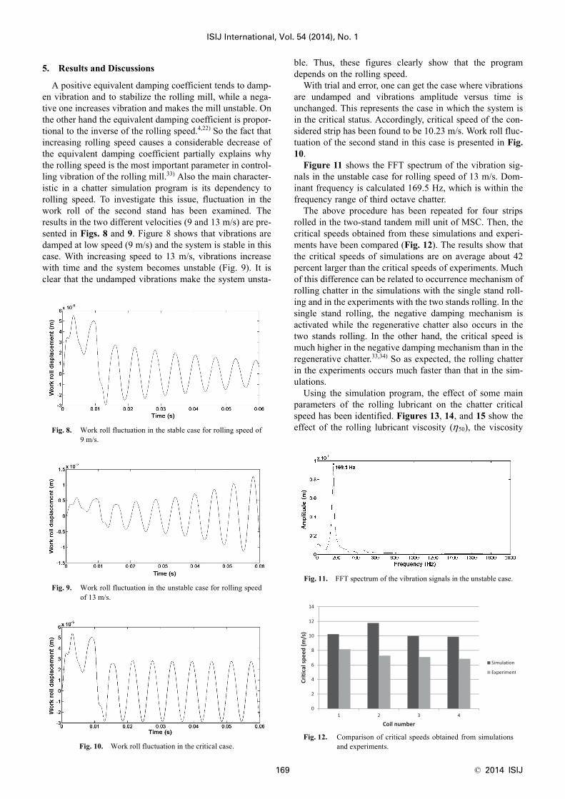
A positive equivalent damping coefficient tends to damp-en vibration and to stabilize the rolling mill, while a nega-tive one increases vibration and makes the mill unstable. Onthe other hand the equivalent damping coefficient is propor-tional to the inverse of the rolling speed.4,22) So the fact thatincreasing rolling speed causes a considerable decrease ofthe equivalent damping coefficient partially explains whythe rolling speed is the most important parameter in control-ling vibration of the rolling mill.33) Also the main character-istic in a chatter simulation program is its dependency torolling speed. To investigate this issue, fluctuation in thework roll of the second stand has been examined. Theresults in the two different velocities (9 and 13 m/s) are pre-sented in Figs. 8 and 9. Figure 8 shows that vibrations aredamped at low speed (9 m/s) and the system is stable in thiscase. With increasing speed to 13 m/s, vibrations increasewith time and the system becomes unstable (Fig. 9). It isclear that the undamped vibrations make the system unsta-
ble. Thus, these figures clearly show that the programdepends on the rolling speed.
With trial and error, one can get the case where vibrationsare undamped and vibrations amplitude versus time isunchanged. This represents the case in which the system isin the critical status. Accordingly, critical speed of the con-sidered strip has been found to be 10.23 m/s. Work roll fluc-tuation of the second stand in this case is presented in Fig.10.
Figure 11 shows the FFT spectrum of the vibration sig-nals in the unstable case for rolling speed of 13 m/s. Dom-inant frequency is calculated 169.5 Hz, which is within thefrequency range of third octave chatter.
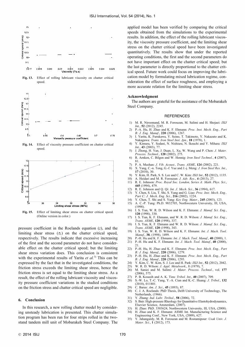
The above procedure has been repeated for four stripsrolled in the two-stand tandem mill unit of MSC. Then, thecritical speeds obtained from these simulations and experi-ments have been compared (Fig. 12). The results show thatthe critical speeds of simulations are on average about 42percent larger than the critical speeds of experiments. Muchof this difference can be related to occurrence mechanism ofrolling chatter in the simulations with the single stand roll-ing and in the experiments with the two stands rolling. In thesingle stand rolling, the negative damping mechanism isactivated while the regenerative chatter also occurs in thetwo stands rolling. In the other hand, the critical speed ismuch higher in the negative damping mechanism than in theregenerative chatter.33,34) So as expected, the rolling chatterin the experiments occurs much faster than that in the sim-ulations.
Using the simulation program, the effect of some mainparameters of the rolling lubricant on the chatter criticalspeed has been identified. Figures 13, 14, and 15 show theeffect of the rolling lubricant viscosity (η50), the viscosityFig. 8. Work roll fluctuation in the stable case for rolling speed of
9 m/s.
Fig. 9. Work roll fluctuation in the unstable case for rolling speedof 13 m/s.
Fig. 10. Work roll fluctuation in the critical case.
Fig. 11. FFT spectrum of the vibration signals in the unstable case.
Fig. 12. Comparison of critical speeds obtained from simulationsand experiments.
© 2014 ISIJ 170
ISIJ International, Vol. 54 (2014), No. 1
pressure coefficient in the Roelands equation (z), and thelimiting shear stress (τL) on the chatter critical speed,respectively. The results indicate that excessive increasingof the first and the second parameter do not have consider-able effect on the chatter critical speed; but the limitingshear stress variation does. This conclusion is consistentwith the experimental results of Yarita et al.3) This can beexpressed by the fact that in the investigated conditions, thefriction stress exceeds the limiting shear stress, hence thefriction stress is set equal to the limiting shear stress. As aresult, the effect of the rolling lubricant viscosity and viscos-ity pressure coefficient variations in the studied conditionson the friction stress and chatter critical speed are negligible.
6. Conclusion
In this research, a new rolling chatter model by consider-ing unsteady lubrication is presented. This chatter simula-tion program has been run for four strips rolled in the two-stand tandem mill unit of Mobarakeh Steel Company. The
applied model has been verified by comparing the criticalspeeds obtained from the simulations to the experimentalresults. In addition, the effect of the rolling lubricant viscos-ity, the viscosity pressure coefficient, and the limiting shearstress on the chatter critical speed have been investigatedquantitatively. The results show that under the reportedoperating conditions, the first and the second parameters donot have important effect on the chatter critical speed; butthe last parameter is directly proportional to the chatter crit-ical speed. Future work could focus on improving the lubri-cation model by formulating mixed lubrication regime, con-sideration the effect of surface roughness, and employing amore accurate relation for the limiting shear stress.
AcknowledgmentThe authors are grateful for the assistance of the Mobarakeh
Steel Company.
REFERENCES
1) M. R. Niroomand, M. R. Forouzan, M. Salimi and H. Shojaei: ISIJInt., 52 (2012), 2245.
2) P.-A. Hu, H. Zhao and K. F. Ehmann: Proc. Inst. Mech. Eng., PartB: J. Eng. Manuf., 220 (2006), 1267.
3) I. Yarita, K. Furukawa, Y. Seino, T. Takimoto, Y. Nakazato and K.Nakagawa: Trans. Iron Steel Inst. Jpn., 18 (1978), 1.
4) Y. Kimura, Y. Sodani, N. Nishiura, N. Ikeuchi and Y. Mihara: ISIJInt., 43 (2003), 77.
5) J. Zhong, H. Yan, J. Duan, L. Xu, W. Wang and P. Chen: J. Mater.Process. Technol., 120 (2002), 275.
6) R. Arnken, C. Bilgen and W. Hennig: Iron Steel Technol., 4 (2007),81.
7) P. A. Meehan: J. Vib. Acoust., Trans. ASME, 124 (2002), 221.8) X. Yang, C.-n. Tong, G.-f. Yue and J.-j. Meng: J. Iron Steel Res. Int.,
17 (2010), 30.9) Y. Kim, H. Park, S. S. Lee and C. W. Kim: ISIJ Int., 52 (2012), 1135.
10) A. Heidari and M. R. Forouzan: J. Adv. Res., 4 (2013), 27.11) R. E. Johnson: Proc. Royal Soc. London, Series A: Math. Phys. Sci.,
445 (1994), 479.12) R. E. Johnson and Q. Qi: Int. J. Mech. Sci., 36 (1994), 617.13) Y. Chen, S. Liu, T. Shi, S. Yang and G. Liao: Proc. Inst. Mech. Eng.,
Part C: J. Mech. Eng. Sci., 216 (2002), 1224.14) Y. Chen, T. Shi and S. Yang: Key Eng. Mater., 245 (2003), 123.15) A. C.-P. Tung: Ph.D. 9832705, Northwestern University, Ill, USA,
(1998).16) I. S. Yun, W. R. D. Wilson and K. F. Ehmann: J. Manuf. Sci. Eng.,
120 (1998), 330.17) I. S. Yun, K. F. Ehmann, and W. R. D. Wilson: J. Manuf. Sci. Eng.,
Trans. ASME, 120 (1998), 337.18) I. S. Yun, K. F. Ehmann and W. R. D. Wilson: J. Manuf. Sci. Eng.,
Trans. ASME, 120 (1998), 343.19) I. S. Yun, W. R. D. Wilson and K. F. Ehmann: Int. J. Mach. Tool.
Manuf., 38, (1998), 1499.20) P.-H. Hu and K. F. Ehmann: Int. J. Mach. Tool. Manuf., 40 (2000), 1.21) P.-H. Hu and K. F. Ehmann: Int. J. Mach. Tool. Manuf., 40 (2000),
21.22) P.-H. Hu, H. Zhao and K. F. Ehmann: Proc. Inst. Mech. Eng., Part
B: J. Eng. Manuf., 220 (2006), 1279.23) P.-H. Hu, H. Zhao and K. F. Ehmann: Proc. Inst. Mech. Eng., Part
B: J. Eng. Manuf., 220 (2006), 1293.24) Y. Kim, C. W. Kim, S. J. Lee and H. Park: ISIJ Int., 52 (2012), 2042.25) W. R. D. Wilson: J. Appl. Metalwork., 1 (1979), 7.26) M. Saniei and M. Salimi: J. Mater. Process. Technol., vol. 177
(2006), 575.27) P. B. Kosasih and A. K. Tieu: Tribol. Int., 40 (2007), 709.28) S.-W. Lo, T.-C. Yang, Y.-A. Cian and K.-C. Huang: J. Tribol., 132
(2010), 011801.29) C. Barus: Am. J. Sci., 45 (1893), 87.30) C. J. A. Roelands: PhD Thesis, Delft University of Technology, The
Netherlands, (1966).31) Y. Zhang: Ind. Lubr. Ttribol., 58 (2006), 72.32) S. Bair: High-pressure Rheology for Quantitative Elastohydrodynamics,
Elsevier Science, Amsterdam, (2007).33) H. Zhao: PhD. 3303624, Northwestern University, Ill, USA, (2008).34) H. Zhao and K. F. Ehmann: ASME Int. Manufacturing Science and
Engineering Conf., New York, USA, (2009), 627.35) Y. Jahangardy, M. R. Forouzan and M. Rostamipour: Usak Univ. J.
Mater. Sci., 1 (2012), 173.
Fig. 13. Effect of rolling lubricant viscosity on chatter criticalspeed.
Fig. 14. Effect of viscosity pressure coefficient on chatter criticalspeed.
Fig. 15. Effect of limiting shear stress on chatter critical speed.(Online version in color.)