Embed Size (px)
Citation preview
DEVELOPMENT OF A STRUCTURAL DESIGN METHODOLOGY FOR
FILAMENT WINDING COMPOSITE ROCKET MOTOR CASE
A THESIS SUBMITTED TO
THE GRADUATE SCHOOL OF NATURAL AND APPLIED SCIENCES
OF
MIDDLE EAST TECHNICAL UNIVERSITY
BY
YAKUP ERTURAN
IN PARTIAL FULFILLMENT OF THE REQUIREMENTS
FOR
THE DEGREE OF MASTER OF SCIENCE
IN
AEROSPACE ENGINEERING
AUGUST 2019


Approval of the thesis:
DEVELOPMENT OF A STRUCTURAL DESIGN METHODOLOGY FOR
FILAMENT WINDING COMPOSITE ROCKET MOTOR CASE
submitted by YAKUP ERTURAN in partial fulfillment of the requirements for the
degree of Master of Science in Aerospace Engineering Department, Middle East
Technical University by,
Prof. Dr. Halil Kalıpçılar
Dean, Graduate School of Natural and Applied Sciences
Prof. Dr. İsmail Hakkı Tuncer
Head of Department, Aerospace Engineering
Assoc. Prof. Dr. Ercan Gürses
Supervisor, Aerospace Engineering, METU
Examining Committee Members:
Assoc. Prof. Dr. Demirkan Çöker
Aerospace Engineering, METU
Assoc. Prof. Dr. Ercan Gürses
Aerospace Engineering, METU
Assoc. Prof. Dr. Barış Sabuncuoğlu
Mechanical Engineering, Hacettepe University
Assoc. Prof. Dr. Hüsnü Dal
Mechanical Engineering, METU
Assist. Prof. Dr. Tuncay Yalçınkaya
Aerospace Engineering, METU
Date: 27.08.2019

iv
I hereby declare that all information in this document has been obtained and
presented in accordance with academic rules and ethical conduct. I also declare
that, as required by these rules and conduct, I have fully cited and referenced all
material and results that are not original to this work.
Name, Surname:
Signature:
Yakup Erturan
v
ABSTRACT
DEVELOPMENT OF A STRUCTURAL DESIGN METHODOLOGY FOR
FILAMENT WINDING COMPOSITE ROCKET MOTOR CASE
Erturan, Yakup
Master of Science, Aerospace Engineering
Supervisor: Assoc. Prof. Dr. Ercan Gürses
August 2019, 83 pages
Filament winding pressure vessels have a unique place in many areas such as space
and ground applications for decades. Filament winding pressure vessels are used in
products where weight is very critical. In such applications, composite winding
pressure vessels have significant advantages over metal pressure vessels due to their
high specific strength.
In this study, it is aimed to design and analyze composite rocket motor cases produced
by the filament winding method. Within the scope of the study, the dome profile,
filament winding angle and strength of the filament winding composite case are
calculated. Two methods are used in the design of dome of the filament winding
pressure bearing containers. One of them gives a geodesic dome profile while the other
is designed with a non-geodesic dome. Since geodesic winding dome design method
limits the design parameters and boundary conditions, non-geodesic winding method,
which provides wider design space, is used in this study.
The fibers must remain stable on the winding mandrel during production and the slip
tendency should also be taken into account in the design of the dome profile.
Therefore, it is necessary to emphasize the importance of finding a suitable winding
pattern by considering both the production and design criteria. 2-D analyses are

vi
performed in ABAQUS program in order to understand the design method better and
to see how the case behaves when subjected to an internal pressure loading.
Keywords: Composite Rocket Motor Casing, Fiber Reinforced Pressure Vessel,
Filament Winding, Non-geodesic Dome Profile

vii
ÖZ
FİLAMAN SARGILI KOMPOZİT ROKET MOTORU GÖVDELERİ İÇİN
YAPISAL TASARIM YÖNTEMİNİN GELİŞTİRİLMESİ
Erturan, Yakup
Yüksek Lisans, Havacılık ve Uzay Mühendisliği
Tez Danışmanı: Doç. Dr. Ercan Gürses
Ağustos 2019, 83 sayfa
Filaman sargılı basınçlı kaplar, onlarca yıldır yer ve uzay uygulamaları gibi birçok
alanda eşsiz bir yere sahiptir. Filaman sargılı basınçlı kaplar, ağırlığın daha kritik
olduğu ürünlerde kullanılır. Bu tür uygulamalarda, kompozit sarım basınçlı kaplar,
yüksek özgül ağırlıklarından dolayı metal basınçlı kaplara göre önemli avantajlara
sahiptir.
Bu çalışmada filaman sarım yöntemiyle üretilen kompozit roket motor gövdelerinin
tasarımı ve analiz ile doğrulanması amaçlanmıştır. Çalışma kapsamında filaman
sarımlı kompozit gövdenin kubbe profili, filaman sarım açısı ve dayanımı sağlayacak
katman kalınlığı hesaplanacaktır. Filaman sargılı basınç taşıyan kapların kubbe
tasarımında genellikle iki yöntem kullanılmaktadır. Bunlardan birisi jeodezik kubbe
profili verirken diğeri ile ise jeodezik olmayan kubbe tasarımı yapılır. Jeodezik sarım
kubbe tasarım parametrelerini ve sınır koşullarını limitlemesinden dolayı bu
çalışmada daha geniş tasarım uzayı sunan jeodezik olmayan sarım yöntemi
kullanılmıştır.
Fiberlerin üretim esnasında mandrel üzerinde stabil durması ve kubbe profili
belirlenmesinde kayma eğiliminin de hesaba katılması gerekmektedir. Bu nedenle
hem üretim hem de tasarım kriterleri göz önünde bulundurularak uygun bir sarım

viii
paterni bulmanın önemini vurgulamak gerekir. Tasarım yöntemini daha iyi anlamak
ve gövdenin yükleme esnasında nasıl davrandığını görmek açısından 2-boyutlu
analizler Abaqus ortamında gerçekleştirilmiştir.
Anahtar Kelimeler: Kompozit Roket Motor Gövdesi, Filaman Takviyeli Basınçlı
Kaplar, Filaman Sargı, Jeodezik Olmayan Kubbe Profili

ix
To my love and my family...
x
ACKNOWLEDGEMENTS
I would like to express my gratitude to Assoc. Prof. Dr. Ercan GÜRSES for his great
guidance, advice and criticism throughout my work.
I also would like to state that this study could not be accomplished without the support
and guidance of my colleagues, Mr. Yusuf ATA, Mr. Emre ÖZASLAN, Mr. Osman
YÜCEL, Mr. Taylan KARPUZCU and Mr. Yavuz YEŞİLYURT. I thank them all.
Above all, I offer my sincere thanks to my love and my family for their support and
courage to finish this thesis with their deepest love.

xi
TABLE OF CONTENTS
ABSTRACT ............................................................................................................ v
ÖZ..............................................................................................................................vii
ACKNOWLEDGEMENTS ..................................................................................... x
TABLE OF CONTENTS ........................................................................................ xi
LIST OF TABLES ................................................................................................ xiii
LIST OF FIGURES .............................................................................................. xiv
CHAPTERS
1. INTRODUCTION ............................................................................................ 1
1.1. Introduction to Composite Solid Rocket Motor Cases .................................... 1
1.2. Introduction to Filament Winding .................................................................. 2
1.2.1. General Use of Filament Wound Products ............................................... 4
1.2.2. Composite Winding over Liner or Mandrel ............................................. 5
1.2.3. Winding Types ........................................................................................ 6
1.3. Introduction to Fiber Reinforced Composite Materials ................................... 8
1.4. Composite Pressure Tanks ........................................................................... 10
1.4.1. Dome Profile of Pressure Tank .............................................................. 11
2. COMPOSITE PRESSURE VESSEL DESIGN THEORY .............................. 15
2.1. Dome Design ............................................................................................... 15
2.2. Stability of Fiber Trajectory on a Curved Surface ........................................ 17
2.3. Geodesic and Non-geodesic Fiber Trajectories ............................................ 19
2.4. Geodesic and Non-geodesic Meridian Profiles ............................................. 24
2.5. Determination of Case Wall Thickness ........................................................ 26

xii
2.6. Cylindrical Region Design ........................................................................... 29
2.7. Polar Boss Design........................................................................................ 29
2.8. Numerical Solution ...................................................................................... 32
3. COMPOSITE ROCKET MOTOR CASE DESIGN AND ANALYSES .......... 37
3.1. Composite Motor Case Design .................................................................... 37
3.2. A Design Example: Design Parameters and Requirements ........................... 39
3.3. Material Properties ...................................................................................... 40
3.4. Dome Design ............................................................................................... 40
3.5. Case Thickness Determination and Cylindrical Region Design .................... 42
3.6. Polar Boss Thickness Design ....................................................................... 43
3.7. FEM Analysis of the Motor Case ................................................................. 45
3.7.1. Modelling and Solution Procedure ........................................................ 46
3.7.2. Analysis Results .................................................................................... 53
3.8. Investigation of the Helical Layer Failure .................................................... 59
4. DOME PARAMETER STUDY ...................................................................... 67
4.1. Effect of Friction Coefficient ....................................................................... 67
4.2. Effect of Dome Opening .............................................................................. 72
5. CONCLUSIONS AND FUTURE RECOMMENDATIONS ........................... 75
5.1. Conclusion .................................................................................................. 75
5.2. Future Work ................................................................................................ 77
REFERENCES ...................................................................................................... 79
xiii
LIST OF TABLES
TABLES
Table 1. Composite rocket motor case design requirements .................................... 39
Table 2. Mechanical properties carbon-epoxy composite........................................ 40
Table 3. Mechanical properties of polar boss material, Aluminum 7075-T6 ........... 40
Table 4. Values of design parameters for various friction coefficients λ ................. 69
Table 5. Design variables for various polar opening 𝜌0 .......................................... 74

xiv
LIST OF FIGURES
FIGURES
Figure 1. General composite motor case architecture ................................................ 2
Figure 2. General construction of a filament winding machine [3] ............................ 4
Figure 3. Filament wound vessels in different geometries [3] ................................... 5
Figure 4. Schematic of a six-axis filament winder [5] ............................................... 7
Figure 5. Basic winding types [6] ............................................................................. 8
Figure 6. Fiber trajectory on a pressure vessel dome [19] ....................................... 11
Figure 7. Free body diagram of fiber on an elementary surface .............................. 18
Figure 8. Fibers and meridian on a dome revolution [19] ....................................... 21
Figure 9. Differential fiber element on a surface [26] ............................................. 23
Figure 10. A laminate under in-plane loads ............................................................ 25
Figure 11. Representation of helical and hoop windings on cylindrical section ....... 28
Figure 12. Netting analysis free body diagram ....................................................... 29
Figure 13. Composite dome with a polar fitting ...................................................... 30
Figure 14. Loadings on polar boss .......................................................................... 30
Figure 15. Dependence of the maximum normalized bending moment on the
normalized radius fitting [40] ................................................................................. 31
Figure 16. Flow chart of the design procedure ........................................................ 34
Figure 17. Different failure modes caused by the failure of the (a) Helical plies, (b)
Hoop plies and (c) Both helical and hoop plies [40] ............................................... 39
Figure 18. Motor case profile along the longitudinal axis ....................................... 41
Figure 19. Fiber angle distribution along the longitudinal axis ............................... 42
Figure 20. 3-D model of the test case ..................................................................... 43
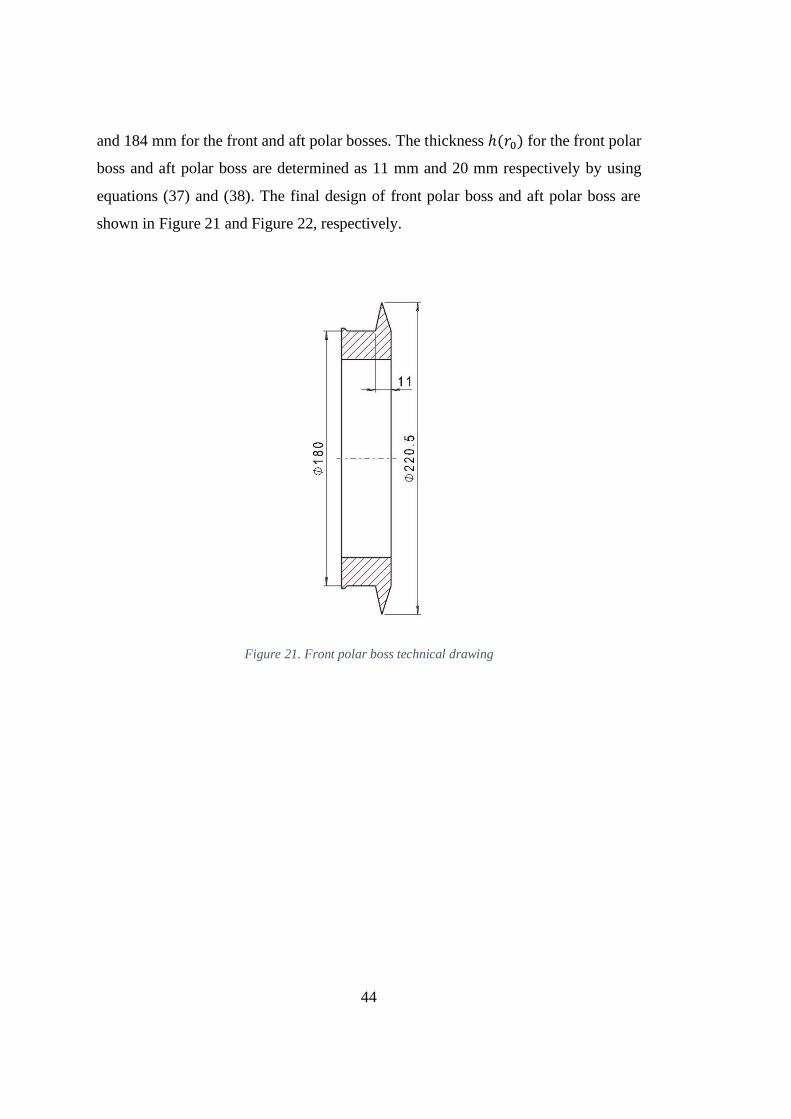
Figure 21. Front polar boss technical drawing ........................................................ 44
Figure 22. Aft polar boss technical drawing ........................................................... 45
Figure 23. Sectional view of the FE-model............................................................. 46
xv
Figure 24. Front dome winding angle comparison for calculated and modeled cases
.............................................................................................................................. 47
Figure 25. Aft dome winding angle comparison for calculated and modeled cases . 48
Figure 26. Ply sequence of the shell ....................................................................... 49
Figure 27. Applied boundary condition on the motor case ...................................... 50
Figure 28. Different mesh densities ........................................................................ 51
Figure 29. Convergence of the results .................................................................... 51
Figure 30. Polar boss region mesh .......................................................................... 52
Figure 31. Cylindrical region mesh ........................................................................ 53
Figure 32. Deformed structure relative to original contour with a scaling factor of 10
.............................................................................................................................. 54
Figure 33. Innermost helical layer fiber direction stress distribution ....................... 55
Figure 34. Outermost helical layer fiber direction stress distribution ...................... 56
Figure 35. Fiber direction stress distribution on innermost and outermost hoop layers
.............................................................................................................................. 57
Figure 36. Von-Mises stresses on aft and front polar bosses ................................... 58
Figure 37. Fiber direction stresses at 26.4 MPa internal pressure load .................... 59
Figure 38. Ply sequence of the shell for 1.2 SF ....................................................... 60
Figure 39. Deformed structure for 1.2 SF ............................................................... 61
Figure 40. Innermost helical layer fiber direction stress distribution for SF 1.2 ...... 62
Figure 41. Outermost helical layer fiber direction stress distribution for SF 1.2 ...... 63
Figure 42. Fiber direction stress distribution on innermost and outermost hoop layers
for SF 1.2 ............................................................................................................... 64
Figure 43. Fiber direction stress values at 1.2 SF .................................................... 65
Figure 44. Effect of friction coefficient on the dome profile with the 0.5 opening ratio
.............................................................................................................................. 68
Figure 45. Effect of friction coefficient on the winding angle distribution with the
0.5 opening ratio .................................................................................................... 69
Figure 46. Effect of negative friction coefficient on the dome profile with the 0.5
opening ratio .......................................................................................................... 71

xvi
Figure 47. Effect of negative friction coefficient on the winding angle distribution with
the 0.5 opening ratio .............................................................................................. 71
Figure 48. Effect of dome opening ratio on the dome profile with the 0.1 friction
coefficient .............................................................................................................. 72
Figure 49. Effect of dome opening ratio on the winding angle distribution with the 0.1
friction coefficient.................................................................................................. 73

1
CHAPTER 1
1. INTRODUCTION
1.1. Introduction to Composite Solid Rocket Motor Cases
Rocket motors carry all the fuel itself. Rocket motor cases form the outer shell of the
system. It serves as the supporting structure and combustion chamber where the fuel
is stored. The rocket motor system forms a mechanical interface with subsystems such
as the nozzle and igniter. It also serves as a pressure vessel. Therefore, the cases are
produced from materials with high strength. Steel, aluminum and composite materials
are the main materials from which rocket motor cases are produced.
The motor case is an inert motor component that does not generate energy. The design
goal is therefore to make the motor case as light as possible with an adequate strength.
Thus, by following this design goal the dead weight of the system decreases and the
efficiency of the motor increases. In particular, the weight of the motor cases produced
with high strength composite materials (carbon/polymer matrix) is much lower than
that of metal ones. The main reason for this is that the composite materials have a
higher specific strength (strength/density). These materials consist of fiber materials
carrying the load and resin material which transfers the load to the fibers.
Composite rocket motor cases are generally manufactured using filament winding
devices. With this technique, the fibers are wound onto a mandrel having the shape of
the motor case. The fibers are located on the rubber insulation material, which protects
the rocket motor from hot gases during combustion, and also acts as a seal to prevent
gases from passing through the composite. A typical composite rocket motor case
consists of the following components [1] as shown in Figure 1:
• Composite skirt rings that connect the engine to the front and rear stages,

2
• Domes and cylinder parts forming the load bearing structure,
• Metal polar bosses forming the mechanical interface of the igniter and nozzle,
• Rubber stress relief to reduce the stress of the interface.
Figure 1. General composite motor case architecture
1.2. Introduction to Filament Winding
Filament winding method is one of the oldest and widely used techniques in the
production of composite pressure vessels. There are two basic ingredients in the
filament winding method, one of which is reinforcement (e.g. fiber) and the other is
matrix (e.g. resin material) [2]. In the filament winding method, resin immersed
reinforcements are wound over a rotating mandrel [3], see Figure 2. Then, under
certain temperature conditions, curing is applied. The winding can be applied for all
axially symmetric structures.
Filament winding is an effective method for the production of composite containers.
In this method, the composite layers are overwrapped onto a mandrel rotating around
its axis. This manufacturing method presents a high-speed and precise process for
placing stacked composite layers. There are two different winding methods depending
on the material used. In the first technique fibers are passed through a resin bath and
wound on a rotating mandrel which is called as wet winding. The latter is prepreg

3
winding in which pre-impregnated fibers are overwrapped on a rotating mandrel.
Among these winding methods, the first technique is more widely used. Compared to
the preliminary preparation, wet winding has several advantages. In wet winding
method material cost is low, winding time is short and matrix material formulation
can be easily changed to meet specific requirements.
Today's filament winding devices are capable of winding at higher speeds, more
accurately at higher degrees of freedom. The mechanical strength of the parts
produced by filament winding depends not only on the material properties but also on
the production process parameters, the winding angle, filament tension, resin
chemistry and maturation cycle.
The filament winding process is generally used for hollow, cylindrical or oval cross-
section shaped structures. The fibers may be dry or withdrawn from a resin bath before
wounded over the mandrel surface. The winding path is commanded by the rotational
speed of the mandrel and the movement of the fiber feed system.
After winding process, the filament-wound mandrel is subjected to curing processes
where the mandrel is rotated to maintain the continuous resin distribution around the
part. After curing cycle, the final product is extracted from the winding mandrel by
dismounting the mandrel.
4
Figure 2. General construction of a filament winding machine [3]
1.2.1. General Use of Filament Wound Products
The filament winding has become a very popular production method in a wide variety
of industrial products to create composite structures with high strength-to-weight
ratios. This manufacturing method has proved to be particularly useful for the
structures used in aerospace and military products, commercial and industrial
structures, as it allows the production of strong, lightweight parts. Both of the
reinforcement and the matrix materials can be specially designed to meet almost all
requirements. This increases the feasibility of the filament winding method in the
production of the various products where the weight efficiency (i.e. strength/weight
ratio) is important. Apart from the durability advantages and low manufacturing cost,
the filament wounded composite parts shows better resistance properties to corrosion
and electrical conductivity.
Cylindrical and spherical pressure tanks (see Figure 3), pipe lines, oxygen and other
fluid containers, rocket motor casings, helicopter rotor blades, large underground
storage tanks (for gasoline, oil, salts, acids, alkalies, water etc.) are the general
applications produced by filament winding technique.

5
Figure 3. Filament wound vessels in different geometries [3]
1.2.2. Composite Winding over Liner or Mandrel
All pressure vessels, tanks or cylindrical pipes made of composite material have a liner
or mandrel. The liner prevents any liquid or gas carried the pressure vessel from
leaking to the exterior. The composite overwrap supplies the strength and stiffness of
the structure. If a fracture exists in the matrix material, the structure may not fail
completely or break down, however the carried fluid may leak outside. Even if the
fibers carry the pressure and hold the structure together, there may be danger if a
flammable fluid is present. Therefore, a flexible lining material is applied to prevent
fluid leakage. The liner can be rubber, a thermoplastic material (e.g. PVC), or a metal
construction made of steel, aluminum or titanium with a thin wall thickness. When the
liner is stiff enough, it can be used as a winding mandrel on which the composite is to
be wound. If the liner is not stiff enough to bear the compressive load during winding,
or when the mandrel has to be removed after winding, new strategies for the mandrel
need to be developed. There are many issues in mandrel design. Important
requirements that the mandrel should have are as follows [4]:
• Mandrel must be stiff enough to bear the compressive load generated during
composite winding,
• The resin material should not adhere to the mandrel surface,
6
• The mandrel must be detachable after the composite structure has matured.
According to places where used and architectural structures mandrels are classified
as, extractable mandrels, collapsible mandrels, breakable mandrels and dissolvable
mandrels.
1.2.3. Winding Types
2-degree of freedom operation is the simplest form of filament winding process. This
operation consists of linear movement of the feeding eye along a rotating mandrel
axis. Pressure containers and cylindrical tubes can be wound with at least 2-axis
filament winding devices. The presence of extra degrees of freedom will be functional
in the winding of the dome portions of the part, the head regions of the pressure vessel,
or parts of varying cross-sections that are more complex than the flat cylinder. For
example, in the case of a 4-axis filament winding machine, the rotation of the mandrel
and the transverse movements of the feeder eye are fundamental movements. The third
axis is the horizontal movement of the feeder eye perpendicular to the mandrel
longitudinal axis. Finally the fourth axis is the feeder eye rotation around its axis. The
third and fourth axes provide a more accurate placement of the fiber. Winding
machines with degree of freedom up to 6 axes are available: mandrel rotation, cross
feed, horizontal carriage movement, vertical carriage movement, wind eye rotation,
and wind eye yaw [5], see Figure 4.

7
Figure 4. Schematic of a six-axis filament winder [5]
According to the coordination of the rotational movement and the axial movement,
three basic winding patterns can be obtained. These are planar, helical winding and
hoop windings [6], see Figure 5. The selection of the winding method for the part to
be produced is made according to the shape of the part and the orientation of the
filaments. In cases where the angle of the fibers is less than 5° with respect to the
longitudinal axis, the planar winding method is used. Helical winding is used in the
winding of fibers that make 5° to 80° with the longitudinal axis. The fibers are wound
in positive and negative directions as an alternative to the mandrel surface. Each
completed helix pattern covering the entire surface of the mandrel results in two layers
of composite material. Helical windings can be applied through the ends of a part. The
hoop windings are a different form of the helical windings and the fiber angle is almost
90 degrees relative to the mandrel’s rotation axis. Generally, hoop winding can be
performed only on non-curved surfaces such as cylindrical or flat areas.

8
Figure 5. Basic winding types [6]
1.3. Introduction to Fiber Reinforced Composite Materials
The mechanical properties of the fiber material predominantly constitute the
mechanical properties of the fiber/resin composite. The contribution of the fibers to
the composite directly related to the four fundamental factors [7]:
• Basic mechanical properties of fiber,
• Fiber and resin surface interaction (interface),
• The amount of fiber inside the composite (fiber volume fraction),
• Orientation of the fibers within the composite.
The strength and quality of fiber/resin interface bond is directly related to the surface
treatment applied to the fiber surface. Surface treatment of fibers is directly associated
with the desired composite performance, fiber type and the process to be applied to
the fibers. The amount of fiber in the composite determines the strength and stiffness

9
of the material. The strength and stiffness values of the composite layer are directly
proportional to the amount of fiber it contains. However, as the fiber volume ratio rises
above 60-70%, the tensile stiffness of the composite material increases, while the layer
strength reaches its highest value and begins to decrease. In this case there is very few
resin material to hold the composite together. The positioning of the fibers in a
composite generally provide greatly to strength. The fibers are materials that their
properties are highly oriented in the loading direction. Therefore, the fibers are
designed to be loaded longitudinally. By placing the fibers in the loading directions,
the amount of material placed can be minimized in the direction in which there is little
or no load.
In composite structures industry commonly used fiber types are carbon fiber, glass
fiber and aramid fiber [8]. Carbon fibers stand out with their great mechanical
properties. Low density, high strength, high fatigue resistance, low thermal expansion,
good electrical and thermal conductivity are important features of carbon fibers. They
are used in structures with ultra-high strength requirements, such as aerospace
structures, high-pressure gas tanks.
Aramid fibers have been used in the industry for 60 years. Aramid fibers are used in
applications that require bullet and impact resistance due to their high vibration
absorption and high energy absorption properties.
Glass fibers are classified into many groups according to their molecular content: A-
glass, C-glass, S-glass, E-glass, etc. Generally E-glass is used in aviation structures.
The glass fibers are manufactured by shaping the glass with a diameter of 1-25
micrometers. Glass fibers are characterized by high shear modulus, low Poisson’s
ratio, good thermal and electrical resistance, and low thermal expansion.
Resin is also a very important component of the composite as an adhesive that bonds
the fibers. The matrix material should have high strength properties, high adhesion
and toughness properties. The matrix should also have good resistance to
environmental conditions. In order to obtain the desired strength properties of the

10
composite, the matrix material must be at least deformed to the same extent as the
fiber. To ensure that the fibers shows efficient transfer of the loads and thus prevents
cracking and debonding good adhesion between the resin and the reinforcing fibers is
required. The measure of toughness is the resistance of the material against crack
propagation. It is important that the amount of final elongation in the fiber is directly
related to the toughness value of the fiber.
Resin materials have two types: thermosets [9] and thermoplastics [10]. Thermoset
materials are hard and insoluble matrix materials formed by irreversible chemical
reaction by mixing the resin with hardener or catalyst. Various thermosets such as
polyester, vinyl-ester and epoxy are used in the composite industry today.
Thermoplastics are materials that soften and eventually melt when heated like metals
and then harden when cooled. Softening or melting at a given temperature range can
be carried out in any number of times desired in both cases without significant change
on the mechanical properties. Acrylic, Nylon, Polypropylene, and Polyethylene are
the general thermoplastics used in the composite industry. Such thermoplastics are
made into stronger composite materials using chopped fibers.
1.4. Composite Pressure Tanks
Composite pressure tanks have been produced by fiber winding method for a long
time. Although it appears as simple structures, the design of pressure vessels is a
difficult task. Filament winding composite pressure vessels have a wide range of use
not only in aviation applications but also in civil and commercial applications.
Originally emerged for military applications, this technology is spread to civilian
structures and expanded to the commercial market at a later stage.
Issues to be considered in the design of the pressure tank are the weight, structural
performance, cost and volume. Composite pressure containers with high specific
strength come up with a remarkable weight gain compared to metal pressure vessels
[11]. Composite pressure tanks are designed to carry the maximum pressure with

11
maximum internal volume and minimum case weight. Accordingly, the performance
factor 𝑃𝑓 = 𝑃𝑉 / 𝑊 is used to rate the efficiency of pressurized tanks. 𝑃, 𝑉, 𝑊 are
the burst pressure, internal volume and weight, respectively [12].
Cylindrical composite pressure tanks consist of a liner and composite overwrap. While
the liner basically provides sealing, some liners contribute to strength by sharing the
stresses due internal loading. Composite pressure tanks should be able to use the
advantages of the mechanical properties (e.g. strength and elastic modulus) of the
material they are produced. To evaluate these properties, the theories of layered
composite materials are comparatively well constructed for the modulus of elasticity
and for less strength. In general, two approaches are used to model the behavior of
composite materials [13].
• Micro-mechanical: composite material is considered as heterogeneous and the
interaction of the components of the composite material taken into account.
• Macro-mechanical: the material is considered to be homogeneous and the
effect of the components is taken into account only using average properties.
1.4.1. Dome Profile of Pressure Tank
In theory the pressure tanks can be of any profile, however it is often used in sphere,
cylinder and cone shapes. The pressure vessel design consists of the cylinder and end
caps called the dome. The dome shapes are generally semi-spherical as shown in
Figure 6. The complex shapes are very difficult in terms of both producibility and
analysis of structural behavior.
Figure 6. Fiber trajectory on a pressure vessel dome [19]

12
Geodesically isotensoid winding method [14], modified helical winding method [15]
and planar winding method [16] are used to determine the winding angle distributions
and dome profile geometries of pressure tanks. In the geodesic domes designed as
isotensoid, the internal pressure is carried only by the fibers and the fibers are loaded
at the same stress quantity. Geodesically isotensoid design method is generally used
for pressure tanks with identical dome apertures at the front and aft domes. The planar
winding pattern is tangential to the dome aperture at one end of the part and extends
in a tangential plane to the dome opening at the other end. They are generally used for
pressure tanks with a length/diameter ratio of less than two. The helical winding dome
profile method is a modified form of the isotensoid dome approach and can be used
for the design of pressure vessels with different dome openings. This method is often
applied in the design of pressure tanks with a length/diameter ratio greater than two.
Since the defined methods concurrently calculates the section profile and the fiber
pattern based on parameters such as the ratio of the dome opening to the cylinder
radius, the initial fiber patterns are retained until the end of the winding process. The
design of the mandrel outer surface pattern can be included in the fiber angle
distribution design.
In theory, the spherical dome shape is the most suitable dome form for an isotropic
pressure vessel. Unfortunately, it is much more difficult to determine the optimum
shape of a composite dome due to the anisotropic character of the dome. With the use
of composite materials having high specific strength values in fiber direction, it is
founded that the preferred dome section profile is isotensoid [17]. The isotensoid is
the case where all the locations on the pressurized dome are at the same tensile stress
level and the stresses are carried only by the fibers. Therefore, there is a direct
relationship between dome section profile, layer stiffness, and filament angles used in
the production operation. Netting theory is used to formulate and solve the isotensoid
dome section method that arises from this interaction between the dome section and
fiber angles. The obtained isotensoid solution approach may take into consideration

13
the special properties of fiber wound pressure tanks such as the size of the dome
apertures, the filament winding technique, such as non-geodesic or planar winding.
The area covered, the weight limit and pressure level are effective in the design of the
relative dimensions of the different parts of a pressure. Since the fiber overwrapped
pressure tanks are often fails in the dome, extra focus must be placed on the dome
section design. This is due to the fact that the dome regions are exposed to the highest
stress levels and they are in the most critical position from the point of view of
structural failure [18]. The main target in the pressure tank design is to reach a higher
burst pressure, higher internal volume and a lower weight.
An important issue to be considered in the production of filament winding pressure
vessels is the fact that an unbalanced increase in the amount of composite can actually
reduce the pressure bearing capacity of the structure. This is because the thicknesses
of extra-composite layer wound structures show change in the stiffness distribution
throughout the tank and thus produce a variation in the isotensoid dome section
profile. Since the dome section profile is usually determined by the mandrel on which
it is wounded and thus cannot be reshaped without the use of tools again, the addition
of wrong filament wrapped layers leads to an unsuccessful design below the required
pressure levels.
The internal pressure load acting along the polar openings are transferred to the
composite shell in the polar boss composite case interface. Therefore, these interfaces
are one of the most stressed areas of filament winding motor cases. On top of it, due
to the rapid change in thickness and curvature in the cylinder/dome joint, excessive
local stress concentrations are observed.


15
CHAPTER 2
2. COMPOSITE PRESSURE VESSEL DESIGN THEORY
In this chapter, a theoretical investigation of a filament wound composite pressure
vessel is detailed. An approach for the determination of the dome profile and fiber
angle distribution as well as the fiber stability is presented.
2.1. Dome Design
The most critical region in pressurized vessels is the dome region. It is important to
determine the dome profile to carry the internal pressure load in the most efficient
way. To this end, the determination of a suitable fiber angle and dome wall thickness
is critical to reduce production challenges and increase structural efficiency. Various
methods have been used to determine the dome profile and layer thickness in the
literature.
Two approaches are used to determine layer thickness: the netting theory and the
continuum theory. There are also two methods available to determine the dome
profile: geodesic and non-geodesic dome profiles. These methods must be well
distinguished in order to determine the required structural features in the best way.
Zu [19] used both methods in the case thickness calculations. The continuum theory
takes both the fibers and the matrix into account and treats the material as orthotropic.
However, in the design calculations using netting theory, only the strength of fibers is
considered. For this reason, continuum theory is more realistic. It should not be
overlooked that netting method is a simplified form of the continuum approach.
Therefore, there is no significant drawback in preferring the netting theory in
preliminary design calculations.
16
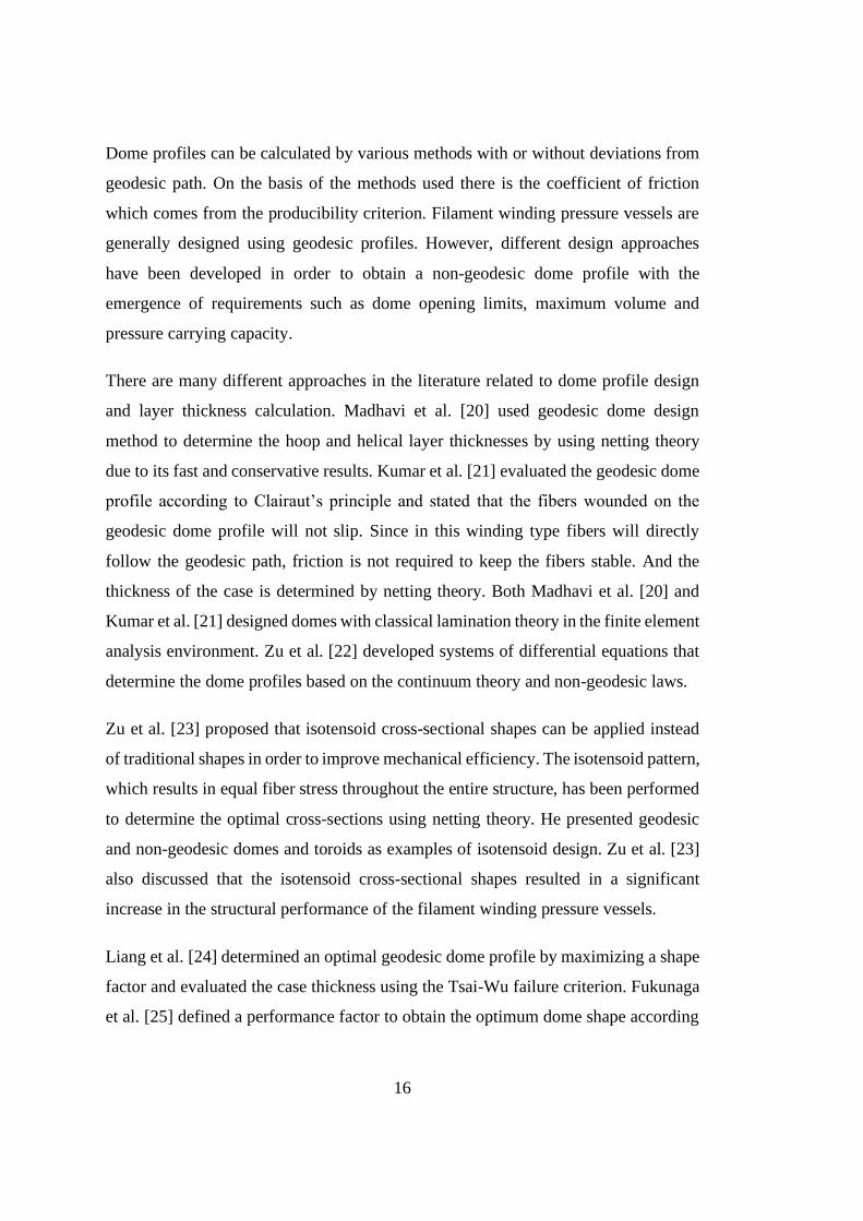
Dome profiles can be calculated by various methods with or without deviations from
geodesic path. On the basis of the methods used there is the coefficient of friction
which comes from the producibility criterion. Filament winding pressure vessels are
generally designed using geodesic profiles. However, different design approaches
have been developed in order to obtain a non-geodesic dome profile with the
emergence of requirements such as dome opening limits, maximum volume and
pressure carrying capacity.
There are many different approaches in the literature related to dome profile design
and layer thickness calculation. Madhavi et al. [20] used geodesic dome design
method to determine the hoop and helical layer thicknesses by using netting theory
due to its fast and conservative results. Kumar et al. [21] evaluated the geodesic dome
profile according to Clairaut’s principle and stated that the fibers wounded on the
geodesic dome profile will not slip. Since in this winding type fibers will directly
follow the geodesic path, friction is not required to keep the fibers stable. And the
thickness of the case is determined by netting theory. Both Madhavi et al. [20] and
Kumar et al. [21] designed domes with classical lamination theory in the finite element
analysis environment. Zu et al. [22] developed systems of differential equations that
determine the dome profiles based on the continuum theory and non-geodesic laws.
Zu et al. [23] proposed that isotensoid cross-sectional shapes can be applied instead
of traditional shapes in order to improve mechanical efficiency. The isotensoid pattern,
which results in equal fiber stress throughout the entire structure, has been performed
to determine the optimal cross-sections using netting theory. He presented geodesic
and non-geodesic domes and toroids as examples of isotensoid design. Zu et al. [23]
also discussed that the isotensoid cross-sectional shapes resulted in a significant
increase in the structural performance of the filament winding pressure vessels.
Liang et al. [24] determined an optimal geodesic dome profile by maximizing a shape
factor and evaluated the case thickness using the Tsai-Wu failure criterion. Fukunaga
et al. [25] defined a performance factor to obtain the optimum dome shape according

17
to several failure criteria. The obtained dome profiles are compared with the isotensoid
dome profiles obtained according to netting theory. Koussios et al. [26] described a
simplified method for the design of isotensoid pressure tanks with different pole
openings using non-geodesic patterns. Furthermore, the performance factor was
calculated to show the efficiency of non-geodesic domes.
2.2. Stability of Fiber Trajectory on a Curved Surface
The stability of the fiber paths is a critical issue in the design procedure. Deflection
from the geodesic trajectory would require a lateral friction force to prevent the fiber
from slipping off the original trajectory. An analysis of the stability of the fiber
trajectories is mandatory and the fibers must be correctly positioned to obtain the most
appropriate performance of the pressure vessel as determined by the structural design.
Ignorance of fiber stability could make the structural design and winding process
unfeasible.
The vector representation of a dome surface is:
𝑆 = 𝑆(𝑢, 𝑣) (1)
Where S is a function defined by (𝑢, 𝑣), and the parameters are distributed in the 𝑢𝑣-
plane. For the surfaces of shell of revolution, the 𝑢 and 𝑣 curves denote meridian and
parallels.
A fiber path on the surface 𝑆(𝑢, 𝑣) can be defined by:
𝐶(𝑠) = 𝐶(𝑢(𝑠), 𝑣(𝑠)) (2)
Where 𝑠 denotes the length of the fiber on the surface 𝑆.
Considering an infinitesimal elementary piece of the fiber, the fiber is under four
acting forces on it. Longitudinal tension forces along the two sides of the infinitesimal
fiber (𝐹0 and 𝐹1), a surface normal reaction force (𝐹𝑛) and a surface tangential friction
force (𝐹𝑓) are the main forces acting on the fiber, see Figure 7 [26].

18
The total curvature of the path of the infinitesimal fiber is the quadratic summation of
the normal and geodesic curvatures, 𝑘𝑛 and 𝑘𝑔 respectively.
𝑘 = 𝑘𝑛2 + 𝑘𝑔
2 (3)
The normal curvature is normal to the supporting mandrel surface while the geodesic
curvature is the in-plane curvature, tangential to the supporting surface, as shown in
Figure 7.
Figure 7. Free body diagram of fiber on an elementary surface
The friction force 𝐹𝑓 must always be less than the maximum static friction between
the support surface and the fiber bundle to prevent fiber slippage on the support
surface:
|𝐹𝑓| ≤ 𝜇𝑚𝑎𝑥|𝐹𝑛| (4)

19
where 𝜇𝑚𝑎𝑥 is the maximum static friction coefficient between the fiber and the
winding surface or between the fiber and the pre-wound layer. Note that it may be
influenced by surface quality, fiber morphology, resin viscosity etc. [27].
The slippage coefficient 𝜆 is defined as the ratio of the geodesic curvature to the
normal curvature [28, 29]:
𝜆 =𝑘𝑔
𝑘𝑛 (5)
The slippage coefficient 𝜆 stands for the shear tendency between the fiber bundle and
the winding surface. Possible fiber patterns can be found by shifting the 𝜆. The
filaments may lose contact with the mandrel surface if their surface force 𝐹𝑛 is in the
same direction as the surface normal.
2.3. Geodesic and Non-geodesic Fiber Trajectories
A three-dimensional surface can be represented as a function of two parameters 𝑢, 𝑣:
𝑆(𝑢, 𝑣) = {𝑥(𝑢, 𝑣), 𝑦(𝑢, 𝑣), 𝑧(𝑢, 𝑣)} (6)
The coefficients of the first fundamental form are [30]:
𝐸 = (𝜕𝑥
𝜕𝑢)
2
+ (𝜕𝑦
𝜕𝑢)
2
+ (𝜕𝑧
𝜕𝑢)
2
= 𝑆𝑢 ∙ 𝑆𝑢
𝐹 = 𝜕𝑥
𝜕𝑢
𝜕𝑥
𝜕𝑣+
𝜕𝑦
𝜕𝑢
𝜕𝑦
𝜕𝑣+
𝜕𝑧
𝜕𝑢
𝜕𝑧
𝜕𝑣= 𝑆𝑢 ∙ 𝑆𝑣 (7)
𝐺 = (𝜕𝑥
𝜕𝑣)
2
+ (𝜕𝑦
𝜕𝑣)
2
+ (𝜕𝑧
𝜕𝑣)
2
= 𝑆𝑣 ∙ 𝑆𝑣
where 𝑆𝑢 and 𝑆𝑣 are the first order derivatives of 𝑆 with respect to the main directions.
𝐸 is the coefficient along the curve of meridional direction of the shell and 𝐺 denotes
the coefficient along the curve of parallel direction. 𝐹 is the inner product of the
meridional and parallel directions. Since meridional and parallel directions of a shell
are perpendicular to each other, 𝐹 will be equal to zero. The second fundamental form
exists as well. The coefficients of the second fundamental form are as follows [30]:

20
𝐿 =
𝑑𝑒𝑡[
𝑆𝑢𝑢𝑆𝑢𝑆𝑣
]
√𝐸𝐺−𝐹2= 𝑛 ∙ 𝑆𝑢𝑢
𝑀 =
𝑑𝑒𝑡[
𝑆𝑢𝑣𝑆𝑢𝑆𝑣
]
√𝐸𝐺−𝐹2= 𝑛 ∙ 𝑆𝑢𝑣 (8)
𝑁 =
𝑑𝑒𝑡[
𝑆𝑣𝑣𝑆𝑢𝑆𝑣
]
√𝐸𝐺−𝐹2= 𝑛 ∙ 𝑆𝑣𝑣
where 𝑆𝑢𝑢 , 𝑆𝑢𝑣 and 𝑆𝑣𝑢 are the second order derivatives of 𝑆 of the main directions.
These coefficients play role in the derivation of the curvature. The unit normal vector
𝑛 of the parametrized surface is expressed as:
𝑛 =𝑆𝑢 × 𝑆𝑣
‖𝑆𝑢 × 𝑆𝑣‖ (9)
Alternatively, the vector representation of a generic surface of revolution can be
written in polar coordinate system as:
𝑆(𝑢, 𝑣) = {𝑓(𝑢) 𝑐𝑜𝑠 𝑣 , 𝑓(𝑢) 𝑠𝑖𝑛 𝑣 , 𝑔(𝑢)} (10)
The meridians and the parallels of the surface 𝑆 are,
𝑆𝑢 = {𝑓′(𝑢) 𝑐𝑜𝑠 𝑣 , 𝑓′(𝑢) 𝑠𝑖𝑛 𝑣 , 𝑔′(𝑢)}
𝑆𝑣 = {−𝑓(𝑢) 𝑠𝑖𝑛 𝑣 , 𝑓(𝑢) 𝑐𝑜𝑠 𝑣 , 0}
𝑛 =𝑆𝑢 × 𝑆𝑣
‖𝑆𝑢 × 𝑆𝑣‖= {−𝑔′(𝑢) 𝑐𝑜𝑠 𝑣 , −𝑔′(𝑢) 𝑠𝑖𝑛 𝑣 , 𝑓′(𝑢)}
𝑆𝑢𝑢 = {𝑓′′(𝑢) 𝑐𝑜𝑠 𝑣 , 𝑓′′(𝑢) 𝑠𝑖𝑛 𝑣 , 𝑔′′(𝑢)}
𝑆𝑢𝑣 = {−𝑓′(𝑢) 𝑠𝑖𝑛 𝑣 , 𝑓′(𝑢) 𝑐𝑜𝑠 𝑣 , 0}
𝑆𝑣𝑣 = {−𝑓(𝑢) 𝑐𝑜𝑠 𝑣 , −𝑓(𝑢) 𝑠𝑖𝑛 𝑣 , 0}
The coefficients of the first and second fundamental forms,
𝐸 = 𝑆𝑢 ∙ 𝑆𝑢 = 𝑓′2 + 𝑔′2 , 𝐹 = 𝑆𝑢 ∙ 𝑆𝑣 = 0 , 𝐺 = 𝑆𝑣 ∙ 𝑆𝑣 = 𝑓2 (11)

21
𝐿 = 𝑛 ∙ 𝑆𝑢𝑢 = − 𝑓′′𝑔′−𝑓′𝑔′′
√𝑓′2+𝑔′2, 𝑀 = 𝑛 ∙ 𝑆𝑢𝑣 = 0, 𝑁 = 𝑛 ∙ 𝑆𝑣𝑣 =
𝑓𝑔′
√𝑓′2+𝑔′2 (12)
The surface vector representation in polar coordinates are written as,
𝑆(𝜃, 𝑧) = {𝑟(𝑧) 𝑐𝑜𝑠 𝜃 , 𝑟(𝑧) 𝑠𝑖𝑛 𝜃 , 𝑧} (13)
where 𝑟 and 𝑧 denote the radial and axial direction and 𝜃 denotes the angular
coordinate as shown in Figure 8 [19].
Figure 8. Fibers and meridian on a dome revolution [19]
The coefficients of the first and second fundamental forms in polar coordinates
becomes:
𝐸 = 𝑟′2 + 1 , 𝐹 = 0 , 𝐺 = 𝑟2 (14)
𝐿 = − 𝑟′′
√𝑟′2+1, 𝑀 = 0, 𝑁 =
𝑟
√𝑟′2+1 (15)
The curvature of a curve indicates the change its direction. The concept that separates
a straight line from a circle is the curvature. As the curvature increases, the straightness
of the curve decreases [31].
22
The curvatures in terms of the first and second fundamental forms are given below
[32, 33]:
𝑘𝑔 = 𝑑𝛼
𝑑𝑠−
𝐸
2√𝐺
𝜕𝑙𝑛𝐸
𝜕𝑣𝑐𝑜𝑠 𝛼 +
1
2√𝐸
𝜕𝑙𝑛𝐺
𝜕𝑢𝑠𝑖𝑛 𝛼 (16)
𝑘𝑛 = (𝐻 + √𝐻2 − 𝐾) 𝑐𝑜𝑠2 𝛼 + (𝐻 − √𝐻2 − 𝐾) 𝑠𝑖𝑛2 𝛼 (17)
where 𝛼 is the fiber angle with respect to the surface meridian and the 𝐻 and 𝐾 are the
parameters defined as below:
𝐾 =𝐿𝑁−𝑀2
𝐸𝐺−𝐹2 (18)
𝐻 =𝐿𝐺−2𝑀𝐹+𝑁𝐸
2(𝐸𝐺−𝐹2) (19)
Substituting the first fundamental forms of the surface into the geodesic and normal
curvature equations 𝑘𝑔 and 𝑘𝑛 one obtains:
𝑘𝑔 = 𝑑𝛼
𝑑𝑠−
𝑟′ 𝑠𝑖𝑛 𝛼
𝑟√1+𝑟′2 (20)
𝑘𝑛 =𝑟′′
(𝑟′2+1)3/2 𝑐𝑜𝑠2 𝛼 +1
𝑟√1+𝑟′2𝑠𝑖𝑛2 𝛼 (21)
After substitution of the above equations (20) and (21) into the equation (5), the
trajectories for the non-geodesic path are defined as:
𝑑𝛼
𝑑𝑠= −𝜆 (
𝑟′′
(𝑟′2+1)3/2 𝑐𝑜𝑠2 𝛼 −1
𝑟√1+𝑟′2𝑠𝑖𝑛2 𝛼) −
𝑟′ 𝑠𝑖𝑛 𝛼
𝑟√1+𝑟′2 (22)
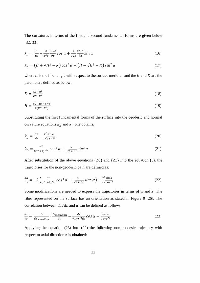
Some modifications are needed to express the trajectories in terms of 𝛼 and 𝑧. The
fiber represented on the surface has an orientation as stated in Figure 9 [26]. The
correlation between 𝑑𝑧/𝑑𝑠 and 𝛼 can be defined as follows:
𝑑𝑧
𝑑𝑠=
𝑑𝑧
𝑑𝑠𝑚𝑒𝑟𝑖𝑑𝑖𝑎𝑛∙
𝑑𝑠𝑚𝑒𝑟𝑖𝑑𝑖𝑎𝑛
𝑑𝑠=
𝑑𝑧
√1+𝑟′2𝑑𝑧𝑐𝑜𝑠 𝛼 =
𝑐𝑜𝑠 𝛼
√1+𝑟′2 (23)
Applying the equation (23) into (22) the following non-geodesic trajectory with
respect to axial direction 𝑧 is obtained:
23
𝑑𝛼
𝑑𝑧= 𝜆 (
𝑠𝑖𝑛 𝛼 𝑡𝑎𝑛 𝛼
𝑟−
𝑟′′
1+𝑟′2 𝑐𝑜𝑠 𝛼) −𝑟′ 𝑡𝑎𝑛 𝛼
𝑟 (24)
The geodesic path of the above trajectories can only be obtained when the 𝜆 is set to
zero. The final equation will be the Clairaut equation [34].
𝑟 𝑠𝑖𝑛 𝛼 = 𝑟0 (25)
where 𝑟0 is the radius of the polar opening of the dome profile as shown in Figure 8.
Other than the fact that the 𝜆 is not zero, the fiber trajectories are named as non-
geodesics. In this case there is no analytical solution for the 𝑑𝛼/𝑑𝑧 equation and a
numerical solution is needed. The Runge-Kutta method [35] can be used for the
numerical solution of the differential equation with the related initial conditions.
The friction coefficient can take values ranging from positive-to-negative to prevent
the fibers from slipping on the surface. In the wet winding method, the coefficient of
friction is generally less than 0.2, whereas for those produced by the dry winding
method, this value can increase up to 0.5 and above [36]. The positive or negative
value of the friction coefficient indicates that the presence of friction increases or
decreases the winding angle [37].
Figure 9. Differential fiber element on a surface [26]

24
In the filament winding industry, the most commonly used filament paths on mandrel
surfaces are constituted by geodesic trajectories which combine two random points on
a curved surface by means of a shortest curve. The geodesic paths mentioned here
have a great stability of winding the fibers on the mandrel surface. However, since the
geodesic paths are calculated by the fiber position and orientation of the initial winding
conditions, limiting the fiber paths to geodesics strictly constraints the existing design
space and the potential performance enhancement of the pressure tanks. Actually, a
filament does not need to be geodesically stable; non-geodesic fiber paths can also be
wound with a certain deviation from geodesic fiber paths using friction to keep the
fiber in its stable position. Therefore, it is acceptable to use geodesics based on friction
coefficient to expand the design alternatives of a fiber winding process. As compared
with the geodesic paths, the non-geodesic winding approach significantly enlarges the
design alternatives for pressure tanks. It is possible to change the 𝜆 value in order to
advantage of further design space for fiber trajectories.
2.4. Geodesic and Non-geodesic Meridian Profiles
Different design methods for dome profiles are used in literature. In the dome design
of composite pressure vessels, there are two basic methods: Geodesic winding and
Non-Geodesic winding. Geodesic winding is obtained by passing the fiber over the
dome at the shortest distance between the starting and ending points and this path is
called geodesic path. The fibers on this path do not slip. When winding on a non-
geodesic path, the fibers follow the path that has a certain slippage tendency.
In this chapter, the governing equations for determining geodesic and non-geodesics
will be outlined with the aid of the continuum theory. Considering a laminate element
(see Figure 10) under the in-plane shell forces (𝑁𝜑, 𝑁𝜃), the ratio of the in-plane shell
forces of the composite shell in the parallel and meridional directions obtained using
the laminated plate theory is given by [19]:
𝑁𝜃
𝑁𝜑=
1−(1−𝑘) 𝑐𝑜𝑠 𝛼2
𝑘+(1−𝑘) 𝑐𝑜𝑠 𝛼2 (26)

25
where 𝑘 is the parameter defined as:
𝑘 =𝐸2 (1+𝜗12)
𝐸1(1+𝜗21) (27)
where 𝐸1 and 𝐸2 are the Young’s moduli in the fiber and transverse directions (1-2),
respectively; 𝜗12 and 𝜗21 are the Poisson’s ratios satisfying the following symmetry
condition:
𝐸1𝜗21 = 𝐸2𝜗12 (28)
The loads that occur in the unit shell loaded with an internal pressure load 𝑃 are
denoted as [38],
𝑁𝜑 = 𝑃𝑟√1+𝑟′2
2 , 𝑁𝜃 =
𝑃𝑟√1+𝑟′2
2(2 +
𝑟𝑟′′
1+𝑟′2) (29)
Figure 10. A laminate under in-plane loads
Combining the equations of in-plane shell forces obtained by both continuum theory
and shell structures theory, (26) and (29) respectively, a non-dimensional equation for
meridian profile is obtained:
26
𝑑2𝜌
𝑑𝜉2 = [1−(1−𝑘) 𝑐𝑜𝑠2 𝛼
𝑘+(1−𝑘) 𝑐𝑜𝑠2 𝛼− 2]
(1+𝜌′2 )
𝜌 (30)
where 𝜌 and 𝜉 are non-dimensional forms of local radius and axial distance
respectively:
𝜌 =𝑟
𝑅 and 𝜉 =
𝑧
𝑅 (31)
Using the non-dimensionalization factors in (31), the trajectory equation obtained in
(24) becomes:
𝑑𝛼
𝑑𝜉= 𝜆 [
(𝑘+2(1−𝑘) 𝑐𝑜𝑠4 𝛼)
𝜌 𝑐𝑜𝑠𝛼(𝑘+(1−𝑘) 𝑐𝑜𝑠2 𝛼)] −
(𝜌′𝑡𝑎𝑛𝛼 )
𝜌 (32)
The above two non-dimensional equations (30) and (32) need to be solved to find the
dome profile along the pressure vessel axis and the trajectory of the fibers to be wound
onto the dome. Simultaneous solution of these equations using specific boundary
conditions and initial conditions gives the dome geometry and fiber orientation. The
fourth order Runge-Kutta algorithm is used to solve the equations. The dome profile
is determined according to the material properties and the desired geometrical and
structural design constraints for a given slippage coefficient value 𝜆. The layer
thickness is determined by using the winding angle value in the dome-cylinder
transition region.
2.5. Determination of Case Wall Thickness
In order to define the mechanical properties of isotropic materials and to make
structural calculations, it is sufficient to know two material constants, the Young’s
elastic moduli and the Poisson’s ratio. However, the material properties in anisotropic
materials vary depending on the direction and the material is characterized with more
elastic constants. Therefore, the mechanical evaluation of composite materials is more
complicated than isotropic materials, and most isotropic approaches do not apply to
composite materials. Some modifications should be made to work with the mechanics
of composite materials.

27
After calculating the dome profile and the fiber trajectory, the thickness of the layer
that will carry the internal pressure load of the case must be determined. Composite
wall thickness carrying the internal pressure load of the body consists of hoop and
helical windings. While the hoop windings provide only circumferential resistance,
the helical windings carry the load in both the circumferential and axial directions.
Netting theory is used in the thesis to determine this thickness. According to the
theory, all of the loads to the case are carried by the fibers and the structural effect of
the resin can be neglected when compared to the stiffness of the fibers.
The fact that the structural contribution of the resin is not considered in netting theory
is an appropriate assumption for vessels carrying internal pressure loads such as the
rocket motor case. Particularly in the rocket motor cases wounded on rubber liner,
resins break at the moment of pressurization and lose their structural properties.
However, the fibers retain the body integrity until they are completely failed.
Therefore, after the pressurization, the fibers carry the internal pressure load by
surrounding the body as a net. As a result, in the theory of the netting, it is assumed
that the whole load is carried by the fibers and the resin matrix that holds the fibers
together has no contribution. This approach does not cause a remarkable fault in the
design process unless there is a load other than the tensile direction of the actual
loading on the fibers. It is also assumed that the rubber liner has no load bearing
capacity when determining thickness.
The strength of the cylinder is provided by hoop and helical windings. Accordingly,
the free body diagram of a cylinder in radius 𝑅 is exposed to internal pressure loading
𝑃 as shown in the Figure 11.

28
Figure 11. Representation of helical and hoop windings on cylindrical section
Loads occurring in the unit element in the cylinder region are shown in Figure 12. The
most important assumption here is that the hoop layers do not contribute to the strength
in the axial direction. The hoop and helical layer thicknesses can be calculated
according to the loading balance on axial and radial directions formed in the unit
elements. The layer thicknesses for a specific winding angle 𝛼 and pressure
requirement 𝑃 can be calculated. Axial load due to internal pressurization is shared in
helical windings as follows:
𝑃𝑅
2= 𝜎𝛼𝑡𝛼 𝑐𝑜𝑠2 𝛼 (33)
The circumferential load is shared in helical and hoop windings as follows:
𝑃𝑅 = 𝜎𝛼𝑡𝛼 𝑠𝑖𝑛2 𝛼 + 𝜎ℎ𝑡ℎ (34)
In the equations, 𝜎𝛼, 𝜎ℎ, 𝑡𝛼, and 𝑡ℎ refer to stresses and thicknesses in helical and hoop
directions, respectively.
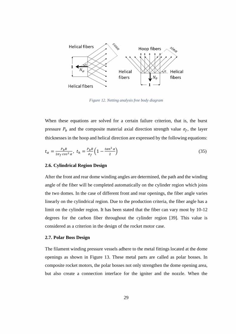
29
Figure 12. Netting analysis free body diagram
When these equations are solved for a certain failure criterion, that is, the burst
pressure 𝑃𝑏 and the composite material axial direction strength value 𝜎𝑓, the layer
thicknesses in the hoop and helical direction are expressed by the following equations:
𝑡𝛼 =𝑃𝑏𝑅
2𝜎𝑓 𝑐𝑜𝑠2 𝛼, 𝑡ℎ =
𝑃𝑏𝑅
𝜎𝑓(1 −
𝑡𝑎𝑛2 𝛼
2) (35)
2.6. Cylindrical Region Design
After the front and rear dome winding angles are determined, the path and the winding
angle of the fiber will be completed automatically on the cylinder region which joins
the two domes. In the case of different front and rear openings, the fiber angle varies
linearly on the cylindrical region. Due to the production criteria, the fiber angle has a
limit on the cylinder region. It has been stated that the fiber can vary most by 10-12
degrees for the carbon fiber throughout the cylinder region [39]. This value is
considered as a criterion in the design of the rocket motor case.
2.7. Polar Boss Design
The filament winding pressure vessels adhere to the metal fittings located at the dome
openings as shown in Figure 13. These metal parts are called as polar bosses. In
composite rocket motors, the polar bosses not only strengthen the dome opening area,
but also create a connection interface for the igniter and the nozzle. When the

30
composite case is pressurized by the internal pressure 𝑃, the polar boss with the
variable thickness distribution ℎ(𝑟) is loaded with the pressure distribution as shown
Figure 14. 𝑃𝑓 is the load distribution due to contact in the polar boss and composite
case interface.
Figure 13. Composite dome with a polar fitting
Figure 14. Loadings on polar boss

31
The load distributions on the polar boss can be reduced as a bending moment and a
transverse shear load. Vasiliev [40] modeled the bending moment on the polar boss
according to the 𝑟𝑓/𝑟0 ratio, see Figure 15.
Figure 15. Dependence of the maximum normalized bending moment on the normalized radius fitting
[40]
Two conditions have been proposed for calculating the thickness of the polar boss,
ℎ(𝑟0). The first condition is the failure of the polar boss due to the bending moment.
Internal pressure load 𝑃, material strength 𝜎𝑦, the largest diameter polar boss 𝑟𝑓 and
normalized bending moment dependent polar boss thickness equation is as follows
[40];
ℎ0 = ℎ(𝑟 = 𝑟0) ≥ 2.3𝑟𝑓√𝑃
𝜎𝑦𝑚𝑟
0(𝑟𝑓) (36)

32
The second condition is the failure of the polar boss due to transverse shear stress. In
this case, according to the shear strength of the material, the minimum thickness of
the polar boss is calculated as [40];
ℎ0 ≥ 3P𝑟0
4𝜏𝑦 (37)
As a result, the parameters necessary for the polar boss design are the burst pressure,
𝑃, the radius of the dome, 𝑟0, and the largest radius of the polar boss. According to the
selected material property, the maximum value of ℎ0 obtained from the above
equations is selected and the design is completed.
2.8. Numerical Solution
There is no analytical solution of the fiber trajectory and meridian profile equations,
(30) and (32). By the help of initial conditions, fiber paths could be calculated step-
by-step using the fourth order Runge-Kutta method. It is necessary to make
modifications in the equations to use this solution procedure. Applying reduction of
order, the equation of the second order is replaced by the following differential system
of first order.
𝜌1 = 𝜌
𝜌2 = 𝜌′ = 𝜌1′ (38)
𝜌3 = 𝜌′′ = 𝜌2′ = [
1−(1−𝑘) cos2 𝛼
𝑘+(1−𝑘) cos2 𝛼− 2]
(1+𝜌22 )
𝜌1
Then the first order system of differential equations to be solved are as follows:
1st equation, fiber trajectory:
𝑑𝛼
𝑑𝜉= 𝜆 [
(𝑘+2(1−𝑘) cos4 𝛼)
𝜌1 𝑐𝑜𝑠𝛼(𝑘+(1−𝑘) cos2 𝛼)] −
(𝜌2𝑡𝑎𝑛𝛼 )
𝜌1= 𝑓1(𝜉, 𝜌1, 𝜌2, 𝛼) (39)
2nd equation, meridian profile:
𝜌1′ = 𝜌2 = 𝑓2(𝜉, 𝜌1, 𝜌2, 𝛼) (40)

33
3rd equation, slope of the dome profile:
𝜌2′ = [
1−(1−𝑘) cos2 𝛼
𝑘+(1−𝑘) cos2 𝛼− 2]
(1+𝜌22 )
𝜌1= 𝑓3(𝜉, 𝜌1, 𝜌2, 𝛼) (41)
The starting point of the fiber is the dome-cylinder transition. Therefore, solution steps
are started from the dome equator. At this point the non-dimensional axial distance 𝜉0
and the local slope of the dome 𝜌’𝑒𝑞 are equal to zero, while the non-dimensional
radius 𝜌𝑒𝑞 is equal to 1. Thus, the initial conditions are as follows:
𝜉0 = 0
𝜌𝑒𝑞 = 𝜌1(0) = 1 , 𝜌′𝑒𝑞 = 𝜌2(0) = 0
Under these initial conditions if the functions of 𝜌 and 𝛼 have values 𝜌𝑖 and 𝛼𝑖 at 𝜉 =
𝜉𝑖, the values of 𝜌𝑖+1and 𝛼𝑖+1 at the next step 𝜉 = 𝜉𝑖 + 𝛥𝜉 are determined by
performing the series of following calculations;
𝛼𝑖+1 =1
6 (𝐾1 + 2 𝐾2 + 2 𝐾3 + 𝐾4)
𝜌1,(𝑖+1) = 𝜌𝑛+1 =1
6 (𝐿1 + 2 𝐿2 + 2 𝐿3 + 𝐿4) (42)
𝜌2,(𝑖+1) =1
6 (𝑍1 + 2 𝑍2 + 2 𝑍3 + 𝑍4)
The formula basically computes next value at 𝑖 + 1 using current value at 𝑖 plus
weighted average of four increments;
• 𝐾1, 𝐿1 and 𝑍1 are the increment based on the slope at the beginning of the
interval 𝜉𝑖,
• 𝐾2, 𝐿2 and 𝑍2 are the increment based on the slope at the midpoint of the
interval 𝜉𝑖 + 𝛥𝜉/2, using 𝐾1, 𝐿1 and 𝑍1,
• 𝐾3, 𝐿3 and 𝑍3 are again the increment based on the slope at the midpoint 𝜉𝑖 +
𝛥𝜉/2, using 𝐾2, 𝐿2 and 𝑍2,
• 𝐾4, 𝐿4 and 𝑍4 are the increment based on the slope at the end of the interval
𝜉𝑖 + 𝛥𝜉, using 𝐾3, 𝐿3 and 𝑍3.

34
The solution procedure of a typical integrated design procedure for filament-wound
composite pressure tanks is outlined in the flow chart shown in Figure 16.
Figure 16. Flow chart of the design procedure
The application of non-geodesic fiber winding application considerably expands the
design alternatives for composite structures. The formulation and consideration of
these fiber paths however, is a rather complex problem. The critical parameter in the
derivations presented here is the geodesic fiber path curvature. In the solution method

35
presented, it is enough to enter the coefficient of slippage as zero to obtain a geodesic
solution.
Consequently, the shape of the meridian and winding pattern will be determined from
the connecting planes between the domes and the cylinder to the dome openings (𝛼 =
90°) by the numerical integration described previously.


37
CHAPTER 3
3. COMPOSITE ROCKET MOTOR CASE DESIGN AND ANALYSES
In order to validate the identified design theory a filament wound rocket motor case is
designed with specific requirements. Finite element analyses are performed using
ABAQUS 2016. Then, the effects of friction coefficient and dome opening ratio on
the design of the composite case are investigated.
3.1. Composite Motor Case Design
The main objective in the design of the composite motor case is to make the motor
case as light as possible within the limits of cost and producibility. The motor cases
designed for this purpose will have a higher motor mass ratio (propellant weight/total
motor weight) and higher performance (acceleration, range, etc.). Motor cases with
high-strength structural composites such as glass fiber, aramid and carbon typically
have a lower weight than metal-case designs. The nature and behavior of composite
materials require different design and quality verification methodologies than those
required for the metal case.
The mechanical, thermal and geometric requirements in the design of the motor case
are provided to the designer. The factor of safety to be applied for the design varies
according to where the missile will be used (space, naval forces, army, air forces, etc.).
The dominant load acting on the motor case is the internal pressure. A typical safety
factor requires the case to have minimum burst strength. This is 1.25 times the
maximum expected operating pressure (MEOP). The safety factor can be increased to
1.4 or 1.5 for man-portable missiles or air defense missiles [41].
Since composite materials start to degrade at much lower temperatures than metallic
materials, it is necessary to pay attention to the thermal loads acting on the motor case.

38
To this end, it is required to determine the temperature limits that the composite case
should not reach and to insulate the required thickness of thermal protection to avoid
this temperature limit. However, it is necessary to know the structural strength and the
stiffness of the case material as well as the environmental conditions to be exposed
during the operation. Because the composite materials are sensitive to temperature,
humidity and other environmental conditions, a detailed material characterization is
very important in the composite case design phase.
In the cylindrical region, the ratio of the tension in the helical layers to the tension in
the hoop layers is called the stress factor;
𝑆𝐹 = 𝜎𝑎𝑙𝑙𝑜𝑤𝑎𝑏𝑙𝑒,𝑎/𝜎𝑎𝑙𝑙𝑜𝑤𝑎𝑏𝑙𝑒,ℎ (43)
where 𝜎𝑎𝑙𝑙𝑜𝑤𝑎𝑏𝑙𝑒,𝑎 and 𝜎𝑎𝑙𝑙𝑜𝑤𝑎𝑏𝑙𝑒,ℎ are the allowable stresses in the helical and hoop
layers respectively. The stress factor is an important design parameter used to control
the burst mode of the motor case. It is almost guaranteed that the hoop layers will be
more likely to fail at lower stress ratios than 0.9, while helical windings will fail at
stress ratios 1.0 and above. The stress ratios between 0.9-1.0 generally result in mixed
mode observations of failure (random failure of helix or hoop layers). Since this leads
to high variability, stress ratios between 0.9-1.0 are not preferred. Figure 17 shows the
different failure modes [40].
The failure of the hoop layers is more preferable because the structural strength is
easier to estimate and the resistance values are less scattered. The failure of the helical
layers resulting in the failure of the dome is mostly due to discontinuities in the polar
boss-dome interface region. For this reason, the tensile strengths of helical windings
are chosen to be lower than the hoop windings so that the required thickness of the
helical layers will be higher. The stress ratio selected in the design of rocket motor
cases is 0.6 to 0.85. This value could be provided by local dome reinforcements or by
winding extra helical layers.

39
Figure 17. Different failure modes caused by the failure of the (a) Helical plies, (b) Hoop plies
and (c) Both helical and hoop plies [40]
3.2. A Design Example: Design Parameters and Requirements
In this study, composite rocket motor case design will be performed according to the
geometric and mechanical requirements given in the Table 1. As a design requirement,
the front polar opening ratio (front opening radius/cylindrical region radius) is taken
as 0.3, and the aft polar opening ratio (aft opening radius/cylindrical region radius) as
0.5.
Table 1. Composite rocket motor case design requirements
Diameter [mm] 600
Length [mm] 1200
Front dome opening (Diameter) [mm] 180
Aft dome opening (Diameter) [mm] 300
Burst pressure [MPa] 25

40
3.3. Material Properties
The material properties given in Table 2 and Table 3 will be used in the design of
composite rocket motor case. Composite motor case shell is carbon-epoxy composite
material with orthotropic linear elastic properties. The front and aft polar boss
materials are chosen as Aluminum 7075-T6.
Table 2. Mechanical properties carbon-epoxy composite
Fiber type IM7
Matrix 8551-7
Fiber volume fraction [%] 60
Longitudinal modulus E1 [GPa] 167
Transverse modulus E2 [GPa] 8.43
Shear modulus G12 [GPa] 4.93
Poisson’s ratio v12 0.27
Tensile strength [MPa] 2550
Table 3. Mechanical properties of polar boss material, Aluminum 7075-T6
Ultimate tensile strength [MPa] 572
Tensile yield strength [MPa] 503
Modulus of elasticity [GPa] 71.7
Poisson’s ratio 0.33
Shear modulus [GPa] 26.9
Shear strength [MPa] 331
3.4. Dome Design
In this section, the aim is to design a carbon fiber reinforced composite rocket motor
case which satisfies the design constraints given in Table 1 and can be produced by
wet filament winding method. To determine the dome geometry, the winding angle
and meridian profile must be determined simultaneously along the motor axis. The
design constraints mentioned in Table 1 and 0.1 friction coefficient are given as input
to the code that simultaneously solves the equations (30) and (32).

41
The solution is found as 11 degrees for the front dome and 25 degrees for the aft dome.
However, the difference of 14 degrees winding angle is too much for producibility. It
is described in the chapter 2.3 that the negative slippage coefficient can be used to
increase the winding angle of the dome. Therefore, the slippage coefficient of the front
dome design is -0.1 and the winding angle were found to be 24 degrees. An angle
change of 1° in the cylindrical region is considered appropriate. Furthermore, the
tangency required for fiber rotation in the pole region, i.e. the winding angle being 90°
is also provided. Figure 18 and 19 present the obtained motor case profile and the
winding angle distribution respectively.
Figure 18. Motor case profile along the longitudinal axis
0
50
100
150
200
250
300
350
0 200 400 600 800 1000 1200 1400
Mo
tor
Cas
e R
adiu
s [m
m]
Motor Case Longitudinal Axis [mm]

42
Figure 19. Fiber angle distribution along the longitudinal axis
3.5. Case Thickness Determination and Cylindrical Region Design
After the design of the domes is completed, the case wall thickness must be determined
for cylindrical and dome regions. The thickness of the cylindrical region consists of
the total thickness of the hoop and helical windings. The theory known as netting
approach is used to determine the wall thickness. In the theory it is assumed that the
acting loads are carried only by the filaments and no load is present in the matrix
material. Equation (35) is used to calculate the hoop and helical layer thicknesses.
The point to be considered here is that the opening ratios of the case are different.
Since the opening ratios are different, the winding angles of the two dome-cylindrical
conjunction regions are also not the same. The case wall thickness is calculated for
the worst case because the winding angle used in the calculation of the composite case
wall thickness is a parameter of the netting theory. In this case, the hoop winding
0
10
20
30
40
50
60
70
80
90
100
0 200 400 600 800 1000 1200 1400
Win
din
g A
ngl
e [°
]
Motor Case Longitudinal Axis [mm]

43
thickness is calculated by using the dome with small angle (24°) and the helical
winding by the large angle dome (25°).
In the design procedure, taking the stress factor as 0.8, it is aimed to make the dome
region more durable and the case will fail from hoop windings. Therefore, hoop layers’
tensile strength is taken 2550 MPa and helical layers’ tensile strength is taken as 2040
MPa. As a result, a total of 5.6 mm composite thickness is calculated, i.e., 2.8 mm
thickness is for the hoop layer and 2.8 mm thickness for the helical layer. The 3-D
model of the motor case is shown in Figure 20.
Figure 20. 3-D model of the test case
3.6. Polar Boss Thickness Design
Vasiliev [40] states that the ratio of 𝑟𝑓 𝑟0⁄ should not exceed 1.3 in properly designed
composite rocket motor cases and recommends that it should be greater than 1.225.
Since weight is an important criterion in composite rocket motor cases, the polar boss,
which is a metal part, should be as small as possible. Therefore, 𝑟𝑓 𝑟0⁄ ratio is selected
here as 1.225 in polar boss design. The outer diameters 𝑟𝑓 are determined as 110 mm
44
and 184 mm for the front and aft polar bosses. The thickness ℎ(𝑟0) for the front polar
boss and aft polar boss are determined as 11 mm and 20 mm respectively by using
equations (37) and (38). The final design of front polar boss and aft polar boss are
shown in Figure 21 and Figure 22, respectively.
Figure 21. Front polar boss technical drawing

45
Figure 22. Aft polar boss technical drawing
3.7. FEM Analysis of the Motor Case
For this study, the rocket motor case produced by filament winding with 1200 mm
length (pole to pole), 600 mm diameter, 180 mm front dome and 300 mm aft dome
opening diameter is considered. Burst pressure of 25 MPa is used in the design and
analysis of the structure. Carbon-epoxy IM7 / 8551-7 composite material is selected
in the development of the whole structure. The fiber volume fraction of the composite
is 0.6. Tensile strength of 2550 MPa is used for the evaluation of the composite. The
winding angle is calculated as 24° in the front dome region and 25° in the aft dome
region in the cylindrical area, and the angle of the filament in the polar opening is 90°
as shown in Figure 19.

46
3.7.1. Modelling and Solution Procedure
The calculated dome profile, winding angle and wall thickness are modeled using the
commercial finite element program Abaqus 2016. Modelling is performed by
following the steps below:
The entire tank geometry definition:
The modelling of the structure starts with the identification of the dome and cylinder
geometry. The dome profile of the pressure tank can be modeled in several ways.
Elliptic, spherical or geodesic shapes can be defined or entered into a table of
individual points. In addition, geometry can be exported from a modeled part in other
CAD programs. In this study, the geometry defining the polar boss and case is created
by importing the required geometric parts to Abaqus / CAE. A section view of the
ultimate model is shown in Figure 23.
Figure 23. Sectional view of the FE-model
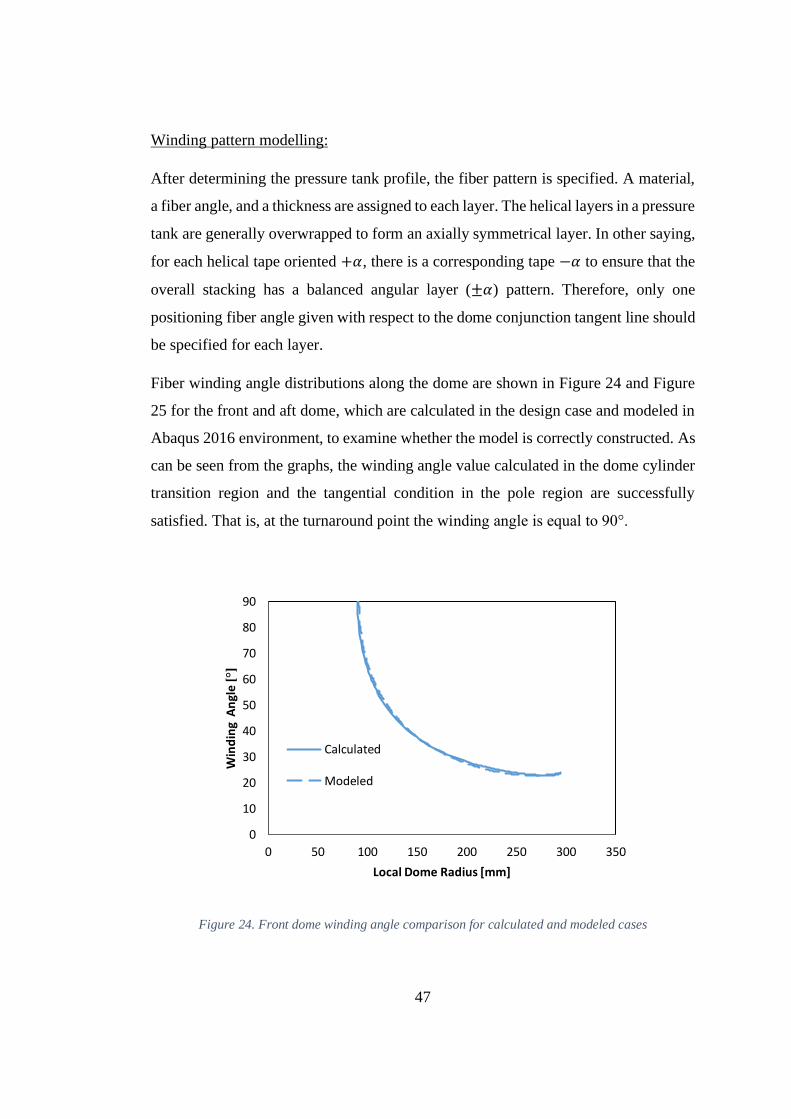
47
Winding pattern modelling:
After determining the pressure tank profile, the fiber pattern is specified. A material,
a fiber angle, and a thickness are assigned to each layer. The helical layers in a pressure
tank are generally overwrapped to form an axially symmetrical layer. In other saying,
for each helical tape oriented +𝛼, there is a corresponding tape −𝛼 to ensure that the
overall stacking has a balanced angular layer (±𝛼) pattern. Therefore, only one
positioning fiber angle given with respect to the dome conjunction tangent line should
be specified for each layer.
Fiber winding angle distributions along the dome are shown in Figure 24 and Figure
25 for the front and aft dome, which are calculated in the design case and modeled in
Abaqus 2016 environment, to examine whether the model is correctly constructed. As
can be seen from the graphs, the winding angle value calculated in the dome cylinder
transition region and the tangential condition in the pole region are successfully
satisfied. That is, at the turnaround point the winding angle is equal to 90°.
Figure 24. Front dome winding angle comparison for calculated and modeled cases
0
10
20
30
40
50
60
70
80
90
0 50 100 150 200 250 300 350
Win
din
g A
ngl
e [°
]
Local Dome Radius [mm]
Calculated
Modeled

48
Figure 25. Aft dome winding angle comparison for calculated and modeled cases
The layers are arranged symmetrically with respect to the mid-plane. For axially
symmetric structures, balanced symmetry is the best option because loading in one
plane does not cause deformations in other planes. In this study, a layer thickness of
0.35 mm is assumed. The sequence of calculated 8 plies hoop and 4 plies helix layers
are determined as shown in Figure 26.
0
10
20
30
40
50
60
70
80
90
0 50 100 150 200 250 300 350
Win
din
g A
ngl
e [
°]
Local Dome Radius
Calculated
Modeled
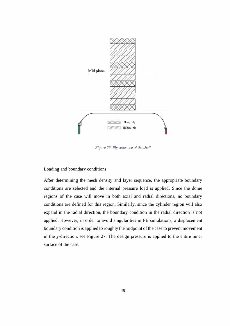
49
Figure 26. Ply sequence of the shell
Loading and boundary conditions:
After determining the mesh density and layer sequence, the appropriate boundary
conditions are selected and the internal pressure load is applied. Since the dome
regions of the case will move in both axial and radial directions, no boundary
conditions are defined for this region. Similarly, since the cylinder region will also
expand in the radial direction, the boundary condition in the radial direction is not
applied. However, in order to avoid singularities in FE simulations, a displacement
boundary condition is applied to roughly the midpoint of the case to prevent movement
in the y-direction, see Figure 27. The design pressure is applied to the entire inner
surface of the case.

50
Figure 27. Applied boundary condition on the motor case
Mesh convergence:
It is important to use different levels of mesh densities to ensure that FEM results are
convergent. The analyses with a coarse mesh may cause inaccurate results. The results
of finite element simulations should converge to a fixed value with mesh refinement.
However, when the mesh is refined, the computer resources used will also increase.
Therefore, has to find the coarsest mesh that is still accurate enough.
A mesh convergence study is carried out before proceeding to detailed analyses. For
this purpose, four different mesh densities are used. For the present case, CAX4 (4-
node bilinear) axisymmetric element type is selected. Figure 28 shows the models with
four different mesh densities.
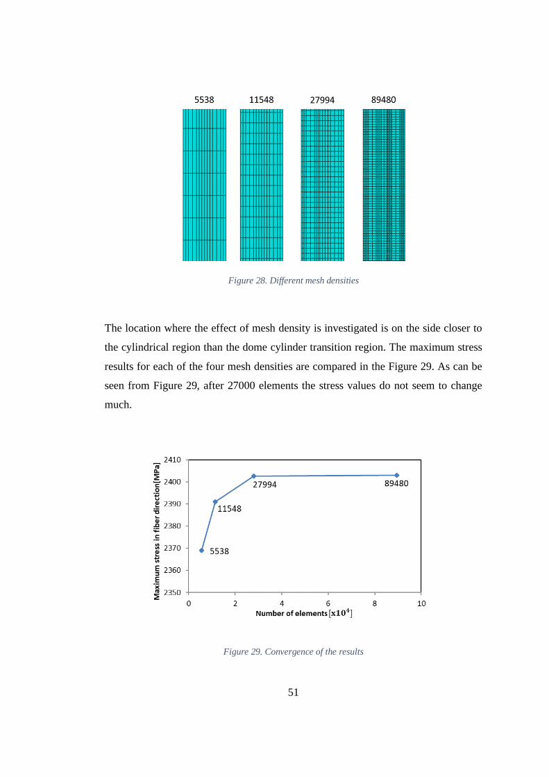
51
Figure 28. Different mesh densities
The location where the effect of mesh density is investigated is on the side closer to
the cylindrical region than the dome cylinder transition region. The maximum stress
results for each of the four mesh densities are compared in the Figure 29. As can be
seen from Figure 29, after 27000 elements the stress values do not seem to change
much.
Figure 29. Convergence of the results

52
From the mesh convergence study, it is decided to use the model with 27994 elements.
The resulting mesh near the polar boss region is shown in Figure 30. In this figure
only the polar boss and a portion of the dome with helical layers are presented.
Figure 30. Polar boss region mesh
The mesh around the dome-cylinder tangency region is shown in Figure 31. The
distributed hoop layers are wounded around the cylindrical portion of the body. The
void locations, where helical layers bridge across ends of hoop layers are meshed and
assigned as matrix as well.

53
Figure 31. Cylindrical region mesh
3.7.2. Analysis Results
The finite element model of the composite pressure tank has been developed to
provide a detailed stress analysis under internal pressure load. The static structural
analysis is conducted to calculate the material deformations and stress distributions.
The deformed shape of the case is shown in Figure 32. The displacement on the case
varies according to the location. The region where the most displacement is observed
is the dome-cylinder conjunction zones. The main reason for this is the rapid change
of the geometry in the dome-cylinder transition region. The cylinder region is thicker
than the dome region. This creates a thickness transition in the junction area. This
creates a stiffness discontinuity on the case and the dome flexes more, causing extra
bending of the end of cylinder region. This behavior is more pronounced in the front

54
dome than the aft dome. This is because the opening of the front dome is smaller and
therefore the pressure integral on the inner surface of the front dome is higher.
Figure 32. Deformed structure relative to original contour with a scaling factor of 10
The fiber direction stresses that occur in the innermost helical layer along the case
from the front pole region are shown in Figure 33. Sudden stress increases are
observed in the dome-cylinder transition zones. This is, as expected, related to the
sensitivity of this region to the thickness transition. A sudden decrease in fiber
direction stresses is observed as expected in polar boss zones. The reason for this is
that the composite layers originating from production accumulate towards the dome

55
opening and this region has a thicker layer. In addition, metal polar bosses share the
internal pressure load.
Figure 33. Innermost helical layer fiber direction stress distribution
Stresses in the fiber direction in the outermost helical layer are also shown in the
Figure 34 along the axis of the case. Similar stress jumps observed in the innermost
helical layer are also occurred in the outermost layer.

56
Figure 34. Outermost helical layer fiber direction stress distribution
The highest fiber direction stresses in the cylindrical region are observed in the
innermost hoop layer. The variation of stresses occurring in this layer along the
cylinder region is shown in Figure 35.
As can be seen from the graph, stress changes are observed at the beginning and end
regions of the layer. The rapid stress changes observed in the helical layers in dome-
cylinder junction areas clearly affect fiber stresses in hoop layers. Note that, the fiber
stress is constant almost away from the transition regions.

57
Figure 35. Fiber direction stress distribution on innermost and outermost hoop layers
When the Mises stresses on the polar bosses are examined, it is seen that the stresses
do not exceed the material strength used, as shown in Figure 36. In addition, such local
stress concentrations can be eliminated by creating a fillet on the sharp regions. As a
result, no failure is expected from polar bosses.
1800
1900
2000
2100
2200
2300
2400
2500
0 200 400 600 800 1000 1200
Stre
ss [
MP
a]
Motor Case Longitudinal Axis [mm]
Innermost hoop layer
Outermost hoop layer
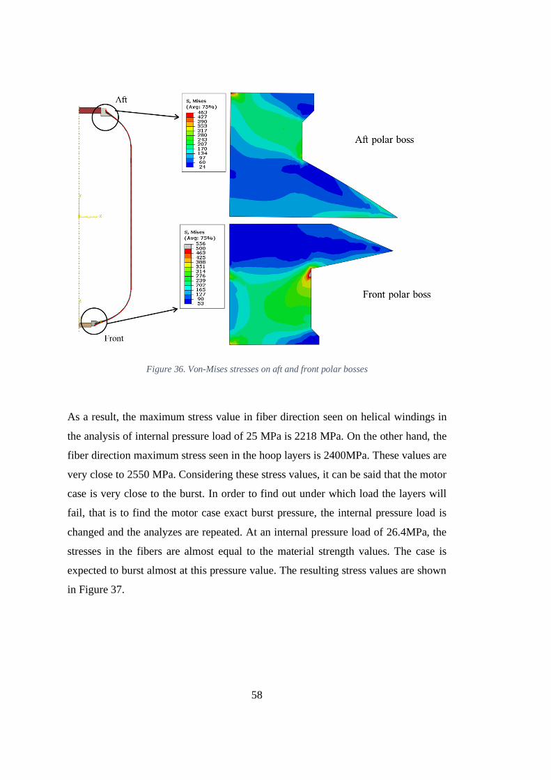
58
Figure 36. Von-Mises stresses on aft and front polar bosses
As a result, the maximum stress value in fiber direction seen on helical windings in
the analysis of internal pressure load of 25 MPa is 2218 MPa. On the other hand, the
fiber direction maximum stress seen in the hoop layers is 2400MPa. These values are
very close to 2550 MPa. Considering these stress values, it can be said that the motor
case is very close to the burst. In order to find out under which load the layers will
fail, that is to find the motor case exact burst pressure, the internal pressure load is
changed and the analyzes are repeated. At an internal pressure load of 26.4MPa, the
stresses in the fibers are almost equal to the material strength values. The case is
expected to burst almost at this pressure value. The resulting stress values are shown
in Figure 37.

59
Figure 37. Fiber direction stresses at 26.4 MPa internal pressure load
3.8. Investigation of the Helical Layer Failure
In this section, the failure of the motor case from helical layers is examined. The
requirements given in the Table 1 are used for the design procedure. The stress factor,
SF determines the burst mode of the composite pressure tank. If SF is greater than 1.0,
the strength of the hoop layers is considered to be lower and more hoop thickness is
calculated. Thus, the tank fails from the helical layers.
In this design process SF is selected as 1.2. Thus, the strength of the helical layers is
taken as 2550 MPa, while the strength of the hoop layers was taken as 2125 MPa.

60
Case thickness for 25 MPa burst pressure is recalculated using equation (35). As a
result, hoop layer thickness is calculated as 3.5 mm and helical layer thickness is 2.1
mm. The total case thickness is calculated as 5.6 mm. Similarly, when the layer
thickness is taken as 0.35 mm, the number of layers is determined as 3 and 10 for
helical and hoop layers respectively. Layer sequence is modeled symmetrically as
shown in the Figure 38.
Since the geometrical properties of the motor case such as polar opening and
cylindrical region diameter do not change, the winding angle and the dome profile will
not change. Moreover, since the design pressure value does not change, the
thicknesses of the polar bosses are the same with the previous motor case. As a result,
only helical and hoop layer thicknesses are changed in this design.
Figure 38. Ply sequence of the shell for 1.2 SF

61
An analysis model is created with the same load and boundary conditions using the
analysis approach applied in Section 3.7. The displacement distribution of the case is
shown in Figure 39. Compared to the previous results in Figure 32, it is observed that
the both cases exhibit similar behavior in the dome transition zones. However, the
displacement values observed in this case of helical failure are slightly larger. The
reason for this is that the dome thickness transition in this design is higher than the
former motor case design. In addition, displacement values observed in the cylinder
region are lower than the results of the first analysis. This is due to the fact that more
hoop layers are used in this design. As a result, in such a design, the cylinder region
is more robust.
Figure 39. Deformed structure for 1.2 SF

62
The fiber direction stresses that occur in the innermost and outermost helical layers
along the case from the front pole region are shown in Figure 40 and Figure 41
respectively. Similar to the Figure 33 and Figure 34 sudden stress increases are
observed in the same transition regions. According to these results, it can be said that
the stress distributions observed on the motor case is mainly caused by the thickness
change occurring in the transition regions, independent of SF.
Figure 40. Innermost helical layer fiber direction stress distribution for SF 1.2
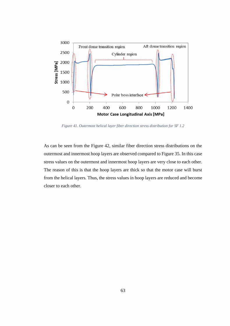
63
Figure 41. Outermost helical layer fiber direction stress distribution for SF 1.2
As can be seen from the Figure 42, similar fiber direction stress distributions on the
outermost and innermost hoop layers are observed compared to Figure 35. In this case
stress values on the outermost and innermost hoop layers are very close to each other.
The reason of this is that the hoop layers are thick so that the motor case will burst
from the helical layers. Thus, the stress values in hoop layers are reduced and become
closer to each other.

64
Figure 42. Fiber direction stress distribution on innermost and outermost hoop layers for SF 1.2
The fiber direction stress values in the cylinder and dome transition zones are shown
in the Figure 43. The maximum fiber direction stress observed in the cylinder region
is approximately 1900 MPa. When the dome transition region is observed, the highest
stress value observed in fiber direction is 2658 MPa. This value is seen in the
innermost helical layer.
Compared to the first case analysis, it is observed that maximum stresses decrease in
the cylinder region and stresses increase in the dome transition region. The main
reason for this is the increase in the thickness of the hoop layer applied to the
cylindrical region. The pressure bearing capacity of the cylinder region increased with
increasing hoop thickness. In addition, as the dome wall thickness decreases, the
bending effect increases in the dome transition zone. For the same reason, the
maximum stress values observed in the first helical layer are higher.
0
500
1000
1500
2000
2500
3000
0 200 400 600 800 1000 1200
Stre
ss [
MP
a]
Motor Case Longitudinal Axis [mm]
Innermost hoop layer
Outermost hoop layer
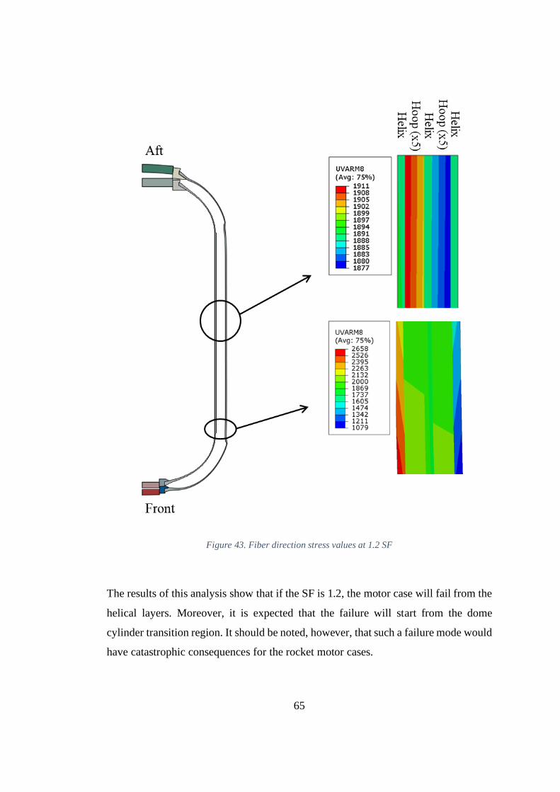
65
Figure 43. Fiber direction stress values at 1.2 SF
The results of this analysis show that if the SF is 1.2, the motor case will fail from the
helical layers. Moreover, it is expected that the failure will start from the dome
cylinder transition region. It should be noted, however, that such a failure mode would
have catastrophic consequences for the rocket motor cases.


67
CHAPTER 4
4. DOME PARAMETER STUDY
In this section, different meridian profiles are presented and examined by changing
the design parameters to validate the applicability of the available approach to creating
pressure tanks at different pole apertures. Dome opening ratio and friction coefficient
are the most critical design parameters in determining dome profile and winding angle.
The effect of different opening ratio and coefficient of friction on the employment of
the fiber winding and dome performance are investigated.
Solving the system of differential equations (30) and (32) synchronously will
eventually provide the geodesic and non-geodesic fiber paths and the associated
section profiles.
4.1. Effect of Friction Coefficient
The objective of the numerical solution method is to employ the couple of design
variables {𝜆, 𝛼} which ensure a 90° fiber angle around the pole opening. The slippage
tendency 𝜆 should belong to a predetermined applicable friction range [-0.5, 0.5]. It
should also be considered that the slippage tendency 𝜆 can be negative [36]. If 𝜆 is
zero, the fibers follow the shortest path on the dome to form the geodesic dome profile,
whereas non-geodesic dome profile is obtained when it is different than zero. Figure
44 shows that the non-geodesic based domes have a slightly larger volume and depth
than the geodesic ones.
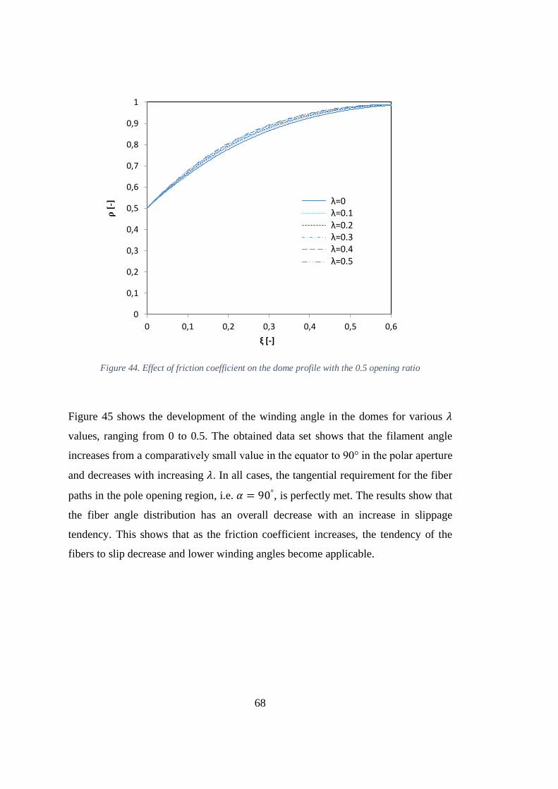
68
Figure 44. Effect of friction coefficient on the dome profile with the 0.5 opening ratio
Figure 45 shows the development of the winding angle in the domes for various 𝜆
values, ranging from 0 to 0.5. The obtained data set shows that the filament angle
increases from a comparatively small value in the equator to 90° in the polar aperture
and decreases with increasing 𝜆. In all cases, the tangential requirement for the fiber
paths in the pole opening region, i.e. 𝛼 = 90°, is perfectly met. The results show that
the fiber angle distribution has an overall decrease with an increase in slippage
tendency. This shows that as the friction coefficient increases, the tendency of the
fibers to slip decrease and lower winding angles become applicable.
0
0,1
0,2
0,3
0,4
0,5
0,6
0,7
0,8
0,9
1
0 0,1 0,2 0,3 0,4 0,5 0,6
ρ[-
]
ξ [-]
λ=0λ=0.1λ=0.2λ=0.3λ=0.4λ=0.5
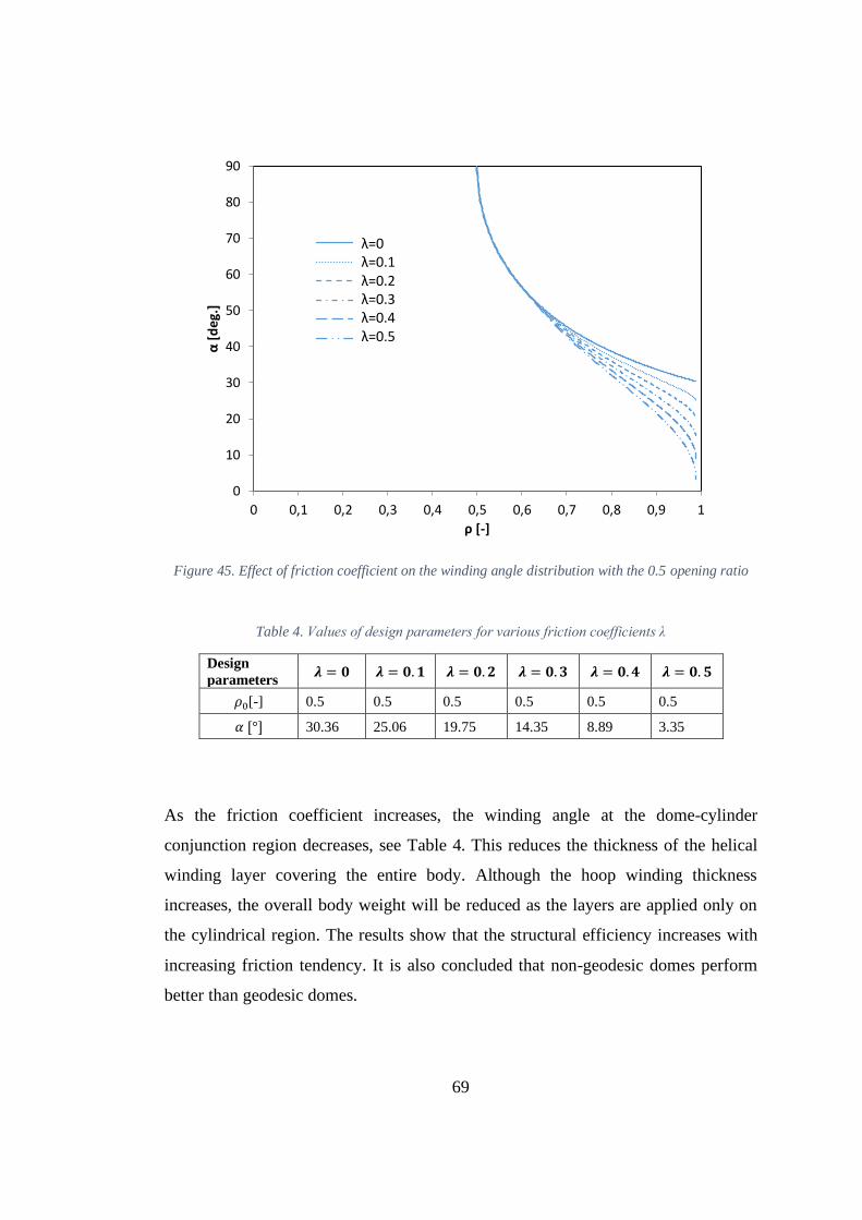
69
Figure 45. Effect of friction coefficient on the winding angle distribution with the 0.5 opening ratio
Table 4. Values of design parameters for various friction coefficients λ
Design
parameters 𝝀 = 𝟎 𝝀 = 𝟎. 𝟏 𝝀 = 𝟎. 𝟐 𝝀 = 𝟎. 𝟑 𝝀 = 𝟎. 𝟒 𝝀 = 𝟎. 𝟓
𝜌0[-] 0.5 0.5 0.5 0.5 0.5 0.5
𝛼 [°] 30.36 25.06 19.75 14.35 8.89 3.35
As the friction coefficient increases, the winding angle at the dome-cylinder
conjunction region decreases, see Table 4. This reduces the thickness of the helical
winding layer covering the entire body. Although the hoop winding thickness
increases, the overall body weight will be reduced as the layers are applied only on
the cylindrical region. The results show that the structural efficiency increases with
increasing friction tendency. It is also concluded that non-geodesic domes perform
better than geodesic domes.
0
10
20
30
40
50
60
70
80
90
0 0,1 0,2 0,3 0,4 0,5 0,6 0,7 0,8 0,9 1
α[d
eg.
]
ρ [-]
λ=0λ=0.1λ=0.2λ=0.3λ=0.4λ=0.5
70
Although the angle of winding reduces and the motor case performance increases, it
should be remembered that the production method (wet or dry filament winding)
should also be evaluated. Because the applicable coefficient of friction is highly
dependent on the winding method.
The dome profiles and winding angle distributions obtained in case of a negative
coefficient of slippage are shown in Figure 46 and Figure 47. As you can see, reducing
the coefficient of slippage decreases the depth and volume of the dome. At the same
time, winding angle values increase. Thus, a thicker composite case with a smaller
volume will be obtained.
In this case, it is clear that the negative slippage tendency is a more inefficient design.
The main purpose of using a negative coefficient of slippage in the design of motor
case with different openings is to increase the winding angle in the dome cylinder
region and to reduce the difference between the winding angle in the other dome-
cylinder transition region. Thus, the angle change over the cylinder region will be less
and the producibility will be increased.

71
Figure 46. Effect of negative friction coefficient on the dome profile with the 0.5 opening ratio
Figure 47. Effect of negative friction coefficient on the winding angle distribution with the 0.5
opening ratio
0
0,1
0,2
0,3
0,4
0,5
0,6
0,7
0,8
0,9
1
0 0,1 0,2 0,3 0,4 0,5 0,6
ρ[-
]
ξ [-]
λ= 0λ= -0.1λ= -0.2λ= -0.3
0
10
20
30
40
50
60
70
80
90
0 0,2 0,4 0,6 0,8 1
α[d
eg
.]
ρ [-]
λ= 0λ= -0.1λ= -0.2λ= -0.3

72
4.2. Effect of Dome Opening
To verify the applicability of creating pressure tanks having different polar apertures
using the present method, fiber paths with constant friction coefficients in the range
of 𝜌0 (from 0.1 to 0.6) are presented in Figure 48.
The filament overwrap procedure requires full tangent positioning of the filaments as
they pass through the polar areas of the dome structure to ensure the continuity of the
filament winding. Therefore, this requirement must be met by applying a non-geodesic
path. The fiber wound angle at the pole must close to 90º. Furthermore, the first
derivative of the 𝑧(𝑟) equation in the dome field reflected in the generated meridian
shape must be equal to zero. Thus, the fiber will be tangent in the pole region and
continue the rotation cycle towards the other dome.
Figure 48. Effect of dome opening ratio on the dome profile with the 0.1 friction coefficient
0
0,1
0,2
0,3
0,4
0,5
0,6
0,7
0,8
0,9
1
0 0,1 0,2 0,3 0,4 0,5 0,6
ρ[-
]
ξ [-]
𝜌0=0.1𝜌0=0.2𝜌0=0.3
𝜌0=0.4
𝜌0=0.5𝜌0=0.6

73
When the effect of opening ratio on winding angle is examined at constant coefficient
of friction, high winding angle gradients are observed in the dome region with
increasing opening ratio. While this creates a production difficulty, the increase in the
opening ratio leads to larger domes in terms of volume and depth. Volume increase
may be an advantage for pressure vessels, but it is also necessary to evaluate the
change in weight to evaluate the design clearly. This situation should be evaluated
according to the actual goal of the design.
Figure 49. Effect of dome opening ratio on the winding angle distribution with the 0.1 friction
coefficient
Assuming the permissible coefficient of friction is 0.1, Table 5 shows the values of
the design parameters {𝜆, 𝛼} for non-geodesics of various dome opening ratio values.
Since the fiber must be tangent with 90° in the dome pole region, the winding angle
value increases as the dome opening ratio increases. This results in thicker helical
windings that will provide the strength of the dome. It should be remembered that with
0
10
20
30
40
50
60
70
80
90
0 0,1 0,2 0,3 0,4 0,5 0,6 0,7 0,8 0,9 1
α[d
eg.]
ρ [-]
𝜌0=0.1𝜌0=0.2𝜌0=0.3𝜌0=0.4𝜌0=0.5𝜌0=0.6
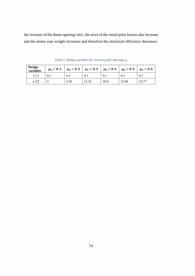
74
the increase of the dome opening ratio, the sizes of the metal polar bosses also increase
and the motor case weight increases and therefore the structural efficiency decreases.
Table 5. Design variables for various polar opening 𝜌0
Design
variables 𝝆𝟎 = 𝟎. 𝟏 𝝆𝟎 = 𝟎. 𝟐 𝝆𝟎 = 𝟎. 𝟑 𝝆𝟎 = 𝟎. 𝟒 𝝆𝟎 = 𝟎. 𝟓 𝝆𝟎 = 𝟎. 𝟔
𝜆 [-] 0.1 0.1 0.1 0.1 0.1 0.1
𝛼 [°] 0 5.02 11.32 18.0 25.06 32.77
75
CHAPTER 5
5. CONCLUSIONS AND FUTURE RECOMMENDATIONS
5.1. Conclusion
The main purpose of this thesis is to provide a design method for filament wound
composite rocket motor cases. Using the specified design method, the motor case with
different dome openings is designed for a given burst pressure value while satisfying
given geometric constraints. The winding angle distributions are calculated utilizing
the negative slippage tendency. Due to the working conditions of the rocket motor
case type pressure vessels, the netting theory is used in the composite case thickness
calculations. A finite element analysis is carried out at the design pressure value and
the body is found to maintain structural integrity at this pressure value. In the burst
pressure investigation analysis, it is found that the case would fail at a pressure value
very close to the pressure used in the design of the composite motor case.
The netting approach is the easiest of the analytical methods applied in the design and
evaluation of composite overwrapped tanks, but is sufficient for fiber winding
pressure tanks. The netting method provides a relationship between internal loading
and fiber stresses occurring in the composite layers of the pressure vessel. In this
study, it is found that the use of netting theory determines the case wall thickness gives
very accurate results and can be used in the design of composite rocket motor cases.
In addition, it is shown that the presented dome profile and the winding angle
determination approach can be used in the design of the general filament wound
pressure vessels.
After verification of the design method and approach, the effects of design parameters
are examined. Since the dome zones are the most sensitive places in terms of
mechanical failure, the design of the domes is one of the most important aspects in a

76
pressure tank design. Starting with the stability analysis of the fiber paths, the design
methods for the geodesic and non-geodesic paths forming the dome geometry of the
pressure vessels are examined.
Even though the profile differences between the geodesic and non-geodesic solutions
are comparatively small, the existing design area has been adequately expanded in the
design of non-geodesic approach. The increase in the design space is particularly
reflected in advanced mechanical performance, while being capable of meeting the
conditions of the winding process.
In the filament winding industry, the most commonly used class of fiber curves are
geodesic trajectories that connect two random points to each other via the shortest
curve on any surface. In the geodesic paths mentioned herein, the fibers show great
stability at the mandrel exterior face. After all, since geodesic paths are completely
specified by stating winding conditions in terms of filament location and orientation,
limiting the fiber paths as geodesics precisely reduces the freedom of design and the
applicable performance advancement of pressure tanks.
Actually, a filament does not need to have geodesic pattern to be stable. The non-
geodesic patterns could also be overwrapped with a particular diversion from the
geodesic patterns, using friction tendency to keep the fibers in their original location.
Therefore, it is necessary to utilize non-geodesic patterns determined through friction
to extend the design area of fiber overwrapped pressure tanks.
Compared to geodesic patterns, the implementation of non-geodesic patterns
considerably extends the design alternatives for pressure tanks. There is the possibility
of changing the value of slippage tendency 𝜆 to give greater design freedom in
determining winding trajectories. As a result, the ability to improve mechanical
efficiency while meeting production requirements becomes a necessity here. Thus,
non-geodesic trajectories can replace conventionally used geodesics and can be used
to improve structural performance. Furthermore, it was shown that the current
77
approach based on non-geodesic winding can be very useful in the design phase of
filament overwrapped pressure tanks with different dome openings.
5.2. Future Work
For the future improvements of the present study, following topics can be proposed:
• Since the netting approach accepts that all loads carried only by the filaments
and neglects the structural contribution of matrix and interference between the
filaments, the available approach can only be considered as a basic design
solution for pressure tanks such as composite rocket motor case. In the further
studies, a more accurate model based on the continuum theory might be
created. However, it is believed that the available approach can be very
advantageous and innovative in the preliminary design phase of fiber
overwrapped domes.
• In this study only general dome profiles such as geodesic and non-geodesic are
obtained. However, fiber angles that can be wound on spherical and elliptical
profiles should be determined and compared with geodesic and non-geodesic
domes in terms of structural performance.
• Loads caused by external factors such as moisture, external heating, vibration,
etc. to which the composite rocket motor cases are exposed can be included in
the structural calculations using knockdown factors.
• In this study, elastomeric rubber lined filament winding rocket engine cases
are designed. In metal-lined composite rocket motor cases, the pressure load
on the case is shared between the metal liner and the composite layer. Design
of metal-lined composite pressure vessels could be made using the existing
dome profile determination method.
In this study, the stacking sequence of the composite layers is determined as
symmetrically distributed. The effect of the stacking sequence on the stresses and
deformations should be investigated to find optimal lay-up. It is also recommended

78
that the proposed design methods for pressure vessels should be detailed and
experimentally verified.

79
REFERENCES
[1] Whitfield, H. K. (1970). Solid Rocket Motor Metal Cases. National Aeronautics
and Space Administration, Vol. 8025
[2] Shaw-Stewart, D. (1985). Filament Winding—Materials & Engineering.
Materials & Design, 6(3), p: 140-144.
[3] Rauf, A. (2017). Design and Fabrication of a Composite Filament Winding
Machine, MSc. thesis report, School of Mechanical and Manufacturing
Engineering, June 2017
[4] Hoa, S. V. (2009). Principles of the Manufacturing of Composite Materials.
DEStech Publications, Inc. Lancaster, PA, USA.
[5] Peters, S. T., Humphrey, W. D., & Foral, R. F. (2009). Filament Winding;
Composite Structure Fabrication, 2nd ed., SAMPE Publishers, Covina, CA,
1994, ©S.T. Peters.
[6] Shen, F. C. (1995). A Filament-Wound Structure Technology Overview.
Materials Chemistry and Physics, 42(2), p: 96-100.
[7] Aastrom, B. T. (1997). Manufacturing of Polymer Composites. London:
Chapman & Hall.
[8] Peters, S. T. and Humphrey, W. D. (1987). Filament Winding. ASM
International, Engineering Materials Handbook, Vol. 1.
[9] Olofsson, S. K. (1995). Filament Winding of Thermoset Composites: Process
Modelling and Experimental Verification. PhD. thesis report. Luleå Tekniska
Universitet, Luleå.

80
[10] Song, X. (2000). Modeling of Thermoplastic Composite Filament Winding.
MSc. thesis report. Virginia Polytechnic Institute and State University,
September 29, 2000.
[11] Kai, F., Liu, Z., Fu, Q., Zheng, J., and Chen, C. (2004). State-of-the-Art of
Fiber-Reinforced High-Pressure Hydrogen Storage Tanks. Journal of
Pressurized Equipment and Systems, 2, p: 59-63.
[12] Teng, T. L., Yu, C. M., and Wu, Y. Y. (2005). Optimal Design of Filament-
Wound Composite Pressure Vessels. Mechanics of Composite Materials, 41(4),
p: 333-340.
[13] Jones, R. M. (1975). Mechanics of Composite Materials. New York:
Hemisphere Publishing Corporation.
[14] Zu, L., Koussios, S., and Beukers, A. (2010). Design of Filament-Wound
Isotensoid Pressure Vessels with Unequal Polar Openings. Composite
Structures, 92(9), p: 2307-2313.
[15] Denost, J. P. (1982). New Design Concepts for Filament-Wound Pressure
Vessel with Unequal Polar Openings. AIAA 18th Joint Propulsion Conference.
[16] Härtung, R. F. (1963). Planar-Wound Filamentary Pressure Vessel. AIAA J,
1(12), p: 2842-2844.
[17] Zickel, J. (1962). Isotensoid Pressure Vessels. ARS Journal, 32, p: 950-951.
[18] Vafaeesefat, A. (2009). Dome Shape Optimization of Composite Pressure
Vessels Based on Rational B-spline Curve and Genetic Algorithm. Applied
Composite Materials, 16(5), p: 321-330.
[19] Zu, L. (2012). Design and Optimization of Filament Wound Composite
Pressure Vessels. MSc. thesis report. Netherlands Box-Press.

81
[20] Madhavi, M. (2009). Design and Analysis of Filament Wound Composite
Pressure Vessel with Integrated-end Domes. Defence Science Journal, 59(1),
p: 73-81.
[21] Kumar, S. S., and Kumari, A. S. (2012). Design and Failure Analysis of
Geodesic Dome of a Composite Pressure Vessel. International Journal of
Engineering Research and Technology, 1(2270-0181).
[22] Zu, L., Koussios, S., and Beukers, A. (2010). Design of Filament–Wound
Domes Based on Continuum Theory and Non-geodesic Roving Trajectories.
Composites Part A: Applied Science and Manufacturing, 41(9), p: 1312-1320.
[23] Zu, L., Wang, J. and Li, S. (2015). Integrated Design and Production of
Filament-Wound Composite Structures: Compromise between Strength and
Manufacturability, 20th International Conference on Composite Materials,
Copenhagen, July 2015.
[24] Liang, C. C., Chen, H. W., and Wang, C. H. (2002). Optimum Design of Dome
Contour for Filament-Wound Composite Pressure Vessels Based on a Shape
Factor. Composite structures, 58(4), p: 469-482.
[25] Fukunaga, H., and Uemura, M. (1983). Optimum design of helically wound
composite pressure vessels. Composite Structures, 1(1), p: 31-49.
[26] Zu, L., Koussios, S., & Beukers, A. (2010). Design of Filament-Wound
Isotensoid Pressure Vessels with Unequal Polar Openings. Composite
Structures, 92(9), p: 2307-2313.
[27] Koussios, S., and Bergsma, O. K. (2006). Friction Experiments for Filament
Winding Applications. Journal of Thermoplastic Composite Materials, 19(1), p:
5-34.

82
[28] De Carvalho, J., Lossie, M., Vandepitte, D., and Van Brussel, H. (1995).
Optimization of Filament-Wound Parts Based on Non-geodesic Winding.
Composites Manufacturing, 6(2), p: 79-84.
[29] Zu, L., Koussios, S., & Beukers, A. (2010). Shape Optimization of Filament
Wound Articulated Pressure Vessels Based on Non-geodesic Trajectories.
Composite Structures, 92, p: 339-346.
[30] Schlichtkrull, H. (2012). Curves and Surfaces: Lecture Notes for Geometry 1.
Department of Mathematical Science, University of Copenhagen.
[31] Shifrin, T. (2015). Differential Geometry: a First Course in Curves and
Surfaces. University of Georgia.
[32] Gray, A. (1993). Modern Differential Geometry of Curves and Surfaces. Boca
Ration: CRC press.
[33] Koussios, S. (2004). Filament Winding: A Unified Approach. PhD thesis report.
Design & Production of Composite Structures, Faculty of Aerospace
Engineering, Delft University of Technology. Delft University Press.
[34] Zwillinger, D. (1997). Clairaut's Equation. Handbook of Differential
Equations, 3rd ed. Academic Press, Boston, MA, p: 120, 158-160.
[35] Boyce, W. E. and DiPrima, R. C., (1986). Elementary Differential Equations
and Boundary Value Problems, New York: John Wiley & Sons.
[36] Wang, R., Jiao, W., Liu, W., Yang, F., and He, X. (2011). Slippage Coefficient
Measurement for Non-geodesic Filament-Winding Process. Composites Part
A: Applied Science and Manufacturing, 42(3), p: 303-309.
[37] Koussios, S., Bergsma, O. K., and Mitchell, G. (2005). Non-geodesic Filament
Winding on Generic Shells of Revolution. Proceedings of the Institution of

83
Mechanical Engineers, Part L: Journal of Materials: Design and Applications,
219(1), p: 25-35.
[38] Denost, J. P. (1988). Design of Filament-Wound Rocket Cases. AGARD,
Design Methods in Solid Rocket Motors, p: 22 (SEE N 89-16906 09-20).
[39] Peters, S. T. (Ed.). (2011). Composite Filament Winding. ASM International.
[40] Vasiliev, V. V. (2009). Composite Pressure Vessels: Analysis, Design, and
Manufacturing. Bull Ridge Corporation.
[41] Evans, P. R. (1988). Composite Motor Case Design. Design Methods in Solid
Rocket Motors, 199356.