Embed Size (px)
Citation preview
UNCLASSIFIED
DEVELOPMENT OF A TEST RIG FOR MEASURING ISENTROPIC BULK MODULUS
INTERIM REPORT TFLRF No. 438
by Scott A. Hutzler
U.S. Army TARDEC Fuels and Lubricants Research Facility
Southwest Research Institute® (SwRI®) San Antonio, TX
for Eric R. Sattler, Patsy A. Muzzell & Nick C. Johnson
U.S. Army TARDEC
Force Projection Technologies Warren, Michigan
Contract No. W56HZV-09-C-0100 (WD0004 – Task XXIII)
UNCLASSIFIED: Distribution Statement A. Approved for public release
January 2013
ADA
UNCLASSIFIED
UNCLASSIFIED
Disclaimers Reference herein to any specific commercial company, product, process, or service by trade name, trademark, manufacturer, or otherwise, does not necessarily constitute or imply its endorsement, recommendation, or favoring by the United States Government or the Department of the Army (DoA). The opinions of the authors expressed herein do not necessarily state or reflect those of the United States Government or the DoA, and shall not be used for advertising or product endorsement purposes.
Contracted Author As the author(s) is(are) not a Government employee(s), this document was only reviewed for export controls, and improper Army association or emblem usage considerations. All other legal considerations are the responsibility of the author and his/her/their employer(s).
DTIC Availability Notice Qualified requestors may obtain copies of this report from the Defense Technical Information Center, Attn: DTIC-OCC, 8725 John J. Kingman Road, Suite 0944, Fort Belvoir, Virginia 22060-6218.
Disposition Instructions Destroy this report when no longer needed. Do not return it to the originator.
UNCLASSIFIED
UNCLASSIFIED
DEVELOPMENT OF A TEST RIG FOR
MEASURING ISENTROPIC BULK MODULUS
INTERIM REPORT TFLRF No. 438
by Scott A. Hutzler
U.S. Army TARDEC Fuels and Lubricants Research Facility
Southwest Research Institute® (SwRI®) San Antonio, TX
for Eric R. Sattler, Patsy A. Muzzell & Nick C. Johnson
U.S. Army TARDEC
Force Projection Technologies Warren, Michigan
Contract No. W56HZV-09-C-0100 (WD0004 – Task XXIII)
SwRI® Project No. 08.14734.04.301
UNCLASSIFIED: Distribution Statement A. Approved for public release
January 2013 Approved by:
Gary B. Bessee, Director U.S. Army TARDEC Fuels and Lubricants
Research Facility (SwRI®)
UNCLASSIFIED
UNCLASSIFIED
REPORT DOCUMENTATION PAGE Form Approved OMB No. 0704-0188
Public reporting burden for this collection of information is estimated to average 1 hour per response, including the time for reviewing instructions, searching existing data sources, gathering and maintaining the data needed, and completing and reviewing this collection of information. Send comments regarding this burden estimate or any other aspect of this collection of information, including suggestions for reducing this burden to Department of Defense, Washington Headquarters Services, Directorate for Information Operations and Reports (0704-0188), 1215 Jefferson Davis Highway, Suite 1204, Arlington, VA 22202-4302. Respondents should be aware that notwithstanding any other provision of law, no person shall be subject to any penalty for failing to comply with a collection of information if it does not display a currently valid OMB control number. PLEASE DO NOT RETURN YOUR FORM TO THE ABOVE ADDRESS. 1. REPORT DATE (DD-MM-YYYY) 31-01-2013
2. REPORT TYPE Interim Report
3. DATES COVERED (From - To) May 2010 – January 2013
4. TITLE AND SUBTITLE Development of a Test Rig for Measuring Isentropic Bulk Modulus
5a. CONTRACT NUMBER W56HZV-09-C-0100
5b. GRANT NUMBER
5c. PROGRAM ELEMENT NUMBER
6. AUTHOR(S) Hutzler, Scott A; Sattler, Eric; Muzzell, Patsy; Johnson, Nick
5d. PROJECT NUMBER SwRI 08.14734.04.301
5e. TASK NUMBER WD 0004 – Task XXIII
5f. WORK UNIT NUMBER
7. PERFORMING ORGANIZATION NAME(S) AND ADDRESS(ES) 8. PERFORMING ORGANIZATION REPORT NUMBER
U.S. Army TARDEC Fuels and Lubricants Research Facility (SwRI®) Southwest Research Institute® P.O. Drawer 28510 San Antonio, TX 78228-0510
TFLRF No. 438
9. SPONSORING / MONITORING AGENCY NAME(S) AND ADDRESS(ES) 10. SPONSOR/MONITOR’S ACRONYM(S)
U.S. Army RDECOM U.S. Army TARDEC 11. SPONSOR/MONITOR’S REPORT Force Projection Technologies NUMBER(S) Warren, MI 48397-5000 12. DISTRIBUTION / AVAILABILITY STATEMENT UNCLASSIFIED: Dist A Approved for public release; distribution unlimited 13. SUPPLEMENTARY NOTES 14. ABSTRACT Bulk modulus is a measure a fluid’s compressibility. In fuel systems, the bulk modulus of the fuel can have a significant impact on fuel behavior and performance in engines by affecting injection timing. While the behavior of most petroleum-derived fuels are well-understood, the emergence of new bio-based and synthetic fuels have demonstrated some properties that are beyond current experience. Therefore, as part of a complete fit-for-purpose analysis, the need for a bulk modulus test rig was identified. The objective of this effort was to design and build a test rig for measuring isentropic bulk modulus at pressures and temperatures up to 30,000 psi and 100°C, respectively. To-date, the measurement of high pressure/temperature speed-of-sound on several fluids has been successfully demonstrated. Plans are underway to incorporate a high pressure/temperature densitometer to improve the bulk modulus accuracy. 15. SUBJECT TERMS Bulk Modulus, Speed-of-Sound, Fuel
16. SECURITY CLASSIFICATION OF: 17. LIMITATION OF ABSTRACT
18. NUMBER OF PAGES
19a. NAME OF RESPONSIBLE PERSON
a. REPORT Unclassified
b. ABSTRACT Unclassified
c. THIS PAGE Unclassified
Unclassified
24
19b. TELEPHONE NUMBER (include area code)
Standard Form 298 (Rev. 8-98) Prescribed by ANSI Std. Z39.18
UNCLASSIFIED iv
UNCLASSIFIED
EXECUTIVE SUMMARY
Bulk modulus is a measure of a fluid’s compressibility. Contrary to popular notions, all fluids do
exhibit some degree of compressibility. In fuel systems, the bulk modulus of the fuel can have a
significant impact on fuel behavior and performance in engines by affecting injection timing.
The trend toward the use of higher pressure, such as in High Pressure Common Rail (HPCR) fuel
systems, demonstrates the need to better understand how the compressibility of fuels are affected
at elevated pressures. While the behavior of most petroleum-derived fuels are well-understood,
the emergence of new bio-based and synthetic fuels have demonstrated some properties that are
beyond current experience. Therefore, as part of a complete fit-for-purpose analysis, the need for
a bulk modulus test rig was identified.
The objective of this effort was to design and build a test rig for measuring isentropic bulk
modulus of hydrocarbon-based fluids - primarily aviation and diesel fuel. The goal was to create
a test rig that can measure the speed-of-sound in fluids at pressures and temperatures up to
30,000 psi and 100°C, respectively.
The measurement of isentropic bulk modulus requires accurate measurement of speed-of-sound
and density at a selected pressure and temperature. To-date, the measurement of high
pressure/temperature speed-of-sound on several fluids has been successfully demonstrated. In
the conduct of this research it was determined that an improved method for density would be
needed to achieve the accuracy desired for bulk modulus. Therefore, plans are underway to
incorporate a high pressure/temperature densitometer to be tentatively completed by the end of
January 2013.
UNCLASSIFIED v
UNCLASSIFIED
FOREWORD/ACKNOWLEDGMENTS
The U.S. Army TARDEC Fuel and Lubricants Research Facility (TFLRF) located at Southwest
Research Institute (SwRI), San Antonio, Texas, performed this work during the period May 2010
through January 2013 under Contract No. W56HZV-09-C-0100. The U.S. Army
Tank Automotive RD&E Center, Force Projection Technologies, Warren, Michigan
administered the project. Mr. Eric Sattler served as the TARDEC contracting officer’s technical
representative. Ms. Patsy Muzzell of TARDEC served as project technical monitor.
The authors would like to acknowledge the contribution of George Lamberson (SwRI) for his
engineering support throughout this effort, the TFLRF technical support staff, and the
administrative and report-processing support provided by Dianna Barrera and Rita Sanchez.
UNCLASSIFIED vi
UNCLASSIFIED
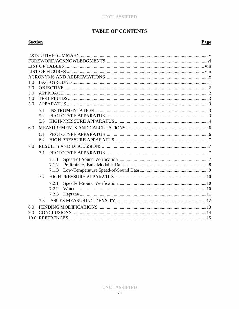
TABLE OF CONTENTS
Section Page
EXECUTIVE SUMMARY .............................................................................................................v FOREWORD/ACKNOWLEDGMENTS ...................................................................................... vi LIST OF TABLES ....................................................................................................................... viii LIST OF FIGURES ..................................................................................................................... viii ACRONYMS AND ABBREVIATIONS ...................................................................................... ix 1.0 BACKGROUND ....................................................................................................................1 2.0 OBJECTIVE ...........................................................................................................................2 3.0 APPROACH ...........................................................................................................................2 4.0 TEST FLUIDS ........................................................................................................................3 5.0 APPARATUS .........................................................................................................................3
5.1 INSTRUMENTATION .................................................................................................3 5.2 PROTOTYPE APPARATUS ........................................................................................3 5.3 HIGH-PRESSURE APPARATUS ................................................................................4
6.0 MEASUREMENTS AND CALCULATIONS.......................................................................6
6.1 PROTOTYPE APPARATUS ........................................................................................6 6.2 HIGH-PRESSURE APPARATUS ................................................................................7
7.0 RESULTS AND DISCUSSIONS ...........................................................................................7
7.1 PROTOTYPE APPARATUS ........................................................................................7
7.1.1 Speed-of-Sound Verification .............................................................................7 7.1.2 Preliminary Bulk Modulus Data ........................................................................8 7.1.3 Low-Temperature Speed-of-Sound Data ...........................................................9
7.2 HIGH PRESSURE APPARATUS ..............................................................................10
7.2.1 Speed-of-Sound Verification ...........................................................................10 7.2.2 Water ................................................................................................................10 7.2.3 Heptane ............................................................................................................11
7.3 ISSUES MEASURING DENSITY .............................................................................12
8.0 PENDING MODIFICATIONS ............................................................................................13 9.0 CONCLUSIONS...................................................................................................................14 10.0 REFERENCES .....................................................................................................................15
UNCLASSIFIED vii
UNCLASSIFIED
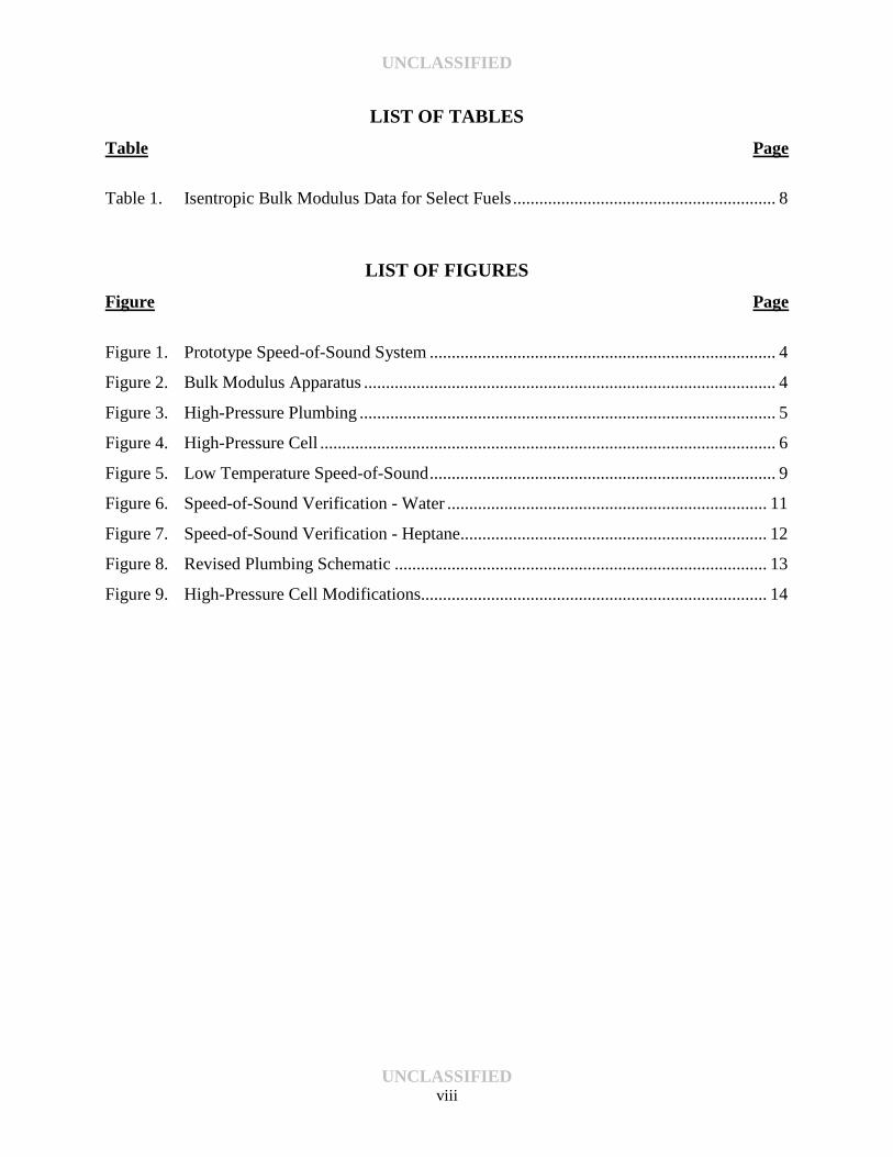
LIST OF TABLES Table Page
Table 1. Isentropic Bulk Modulus Data for Select Fuels ............................................................ 8
LIST OF FIGURES Figure Page
Figure 1. Prototype Speed-of-Sound System ............................................................................... 4
Figure 2. Bulk Modulus Apparatus .............................................................................................. 4
Figure 3. High-Pressure Plumbing ............................................................................................... 5
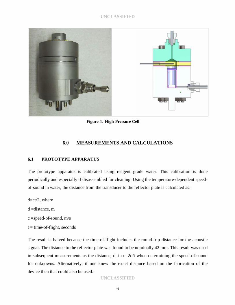
Figure 4. High-Pressure Cell ........................................................................................................ 6
Figure 5. Low Temperature Speed-of-Sound ............................................................................... 9
Figure 6. Speed-of-Sound Verification - Water ......................................................................... 11
Figure 7. Speed-of-Sound Verification - Heptane...................................................................... 12
Figure 8. Revised Plumbing Schematic ..................................................................................... 13
Figure 9. High-Pressure Cell Modifications............................................................................... 14
UNCLASSIFIED viii
UNCLASSIFIED
ACRONYMS AND ABBREVIATIONS AFRL Air Force Research Lab
HPCR High Pressure Common Rail
SwRI Southwest Research Institute
WPAFB Wright Patterson Air Force Base
UNCLASSIFIED ix
UNCLASSIFIED
1.0 BACKGROUND
Bulk modulus is a property that indicates the compressibility of a fluid. Bulk modulus has an
inverse relationship with compressibility. Contrary to popular notions, all fluids do exhibit some
degree of compressibility. In systems that require a fast response to an applied load, such as
hydraulically actuated systems, a highly compressible fluid can lead to a delayed response. In
fuel systems, the bulk modulus of the fuel can have a significant impact on fuel behavior and
performance in engines by affecting injection timing due to higher pressures. The trend toward
the use of higher pressure, such as in High Pressure Common Rail (HPCR) fuel systems,
demonstrates the need to better understand how the compressibility of fuels are affected at
pressures approaching 30,000 psi.
While the behavior of most petroleum-derived fuels are well-understood, the emergence of new
bio-based and synthetic fuels created cause for concern. While still hydrocarbon-based, the
varying chemical composition of these alternative fuels have been shown to create a range of
compressibilities. Therefore, as part of a complete fit-for-purpose analysis, the need for a bulk
modulus test rig was identified. Two general approaches exist for determining the bulk modulus
of compressibility for fluids: the isothermal method and the isentropic method.
The isothermal method is based on classical pressure-volume-temperature measurements.
ASTM D6793 defines a method and apparatus for determining the isothermal bulk modulus.
Isentropic bulk modulus is typically calculated from speed-of-sound measurements. When a fluid
is compressed it’s temperature rises. As the temperature rises, the fluid tries to expand causing an
additional increase in pressure. When compression occurs slowly, as in the isothermal method,
the generated heat is allowed to dissipate reducing the effect of thermal expansion. Rapid
compression, as in the isentropic method, results in a pressure measurement due to compression
and thermal expansion. Most hydraulic applications are considered isentropic due to the rapid
movement of tightly controlled systems. Therefore, the isentropic method is often the preferred
technique.
UNCLASSIFIED 1
UNCLASSIFIED
Isentropic methodology is based on the relationship β = c2 x ρ , where β is the isentropic bulk
modulus, c is the speed-of-sound in the fluid, and ρ is the density all measured under a given set
of pressure and temperature conditions.
2.0 OBJECTIVE
The objective of this effort was to design and build a test rig for measuring isentropic bulk
modulus of hydrocarbon-based fluids - primarily aviation and diesel fuel. The goal was to create
a test rig that can measure the speed-of-sound in fluids at pressures and temperatures up to
30,000 psi and 100°C, respectively.
The objective of this report is to document the status of the test rig to date and provide an update
on the pending modifications to the rig based on our initial findings. Several aspects of the
operation of this apparatus will change once the modifications to the system are complete. All of
the planned modifications are designed to make the system more accurate and more
user-friendly. A detailed operating manual will be developed once the system is reassembled.
3.0 APPROACH
Prior to undertaking the build-up of the full-scale, high-pressure model, a small, benchtop
prototype system was built to confirm our ability to accurately measure speed-of-sound.
Although only able to operate at atmospheric pressure and temperatures up to 50°C, the
prototype system was found to provide highly accurate speed-of-sound data and was used to
build an initial database of comparative isentropic bulk modulus data on a wide range of fuels
(see Section 7.1). Once this was accomplished successfully, we moved on to construct the
full-scale system. Both systems are able to make use of the same basic instrumentation.
UNCLASSIFIED 2
UNCLASSIFIED
4.0 TEST FLUIDS
A variety of petroleum-based and alternative fuels were used in this effort. All of the alternative
aviation fuels and their blends were provided by AFRL (WPAFB). The petroleum-based fuels
and biodiesels were on-hand at SwRI.
5.0 APPARATUS
5.1 INSTRUMENTATION The instrumentation required to create and measure the acoustic signals is common to both the
prototype and high-pressure apparatus. A pulser/receiver unit (Olympus 5072-PR) is used to
drive the ultrasonic transducer and the signals generated are measured using a digital
oscilloscope (LeCroy WaveSurfer 24MXs-A). The oscilloscope is used to measure the time-of-
flight of the acoustic signals as they reflect off internal surfaces and return to the transducer. The
prototype system uses a single-element immersion transducer (Olympus V326-SU, 5MHz) that is
capable of direct contact with the fuel but limited to approximately 50°C maximum temperature.
The high-pressure system uses a dual element transducer (Olympus 791-RM, 5MHz) which is
able to tolerate temperatures exceeding 100°C. Experiments were also conducted with an
Olympus DHC706-RM (dual element, 2.25 MHz) transducer and found to give better signal
quality. This will likely be the choice of transducer for subsequent designs.
5.2 PROTOTYPE APPARATUS The prototype system, shown in Figure 1, consists of an ultrasonic immersion transducer wedged
between two plates. The lower plate acts as a platform to support the apparatus on top of a
beaker filled with the test fluid. The cruciform design of the mounting bolts allows the transducer
angle to be adjusted in small increments to improve the signal strength and remove echoes
caused by reflections from the walls. The cylinder below the plates includes a highly-polished
reflector plate as the target for the ultrasonic pulse. A small hole through the plates allows a
thermocouple to be inserted to measure the fluid temperature. UNCLASSIFIED
3

UNCLASSIFIED
Figure 1. Prototype Speed-of-Sound System
5.3 HIGH-PRESSURE APPARATUS The high-pressure bulk modulus apparatus in its original configuration (Figure 2) consists of the
high-pressure components (Figure 3) housed in a high-temperature oven. The high pressure
components consist of the custom high-pressure cell (Figure 3, lower left), a high-pressure
generator (Figure 3, lower right), a pressure transducer (Figure 3, center left), and inlet/outlet
valves. Other peripheral equipment (not shown) are a peristaltic pump to transfer fuel in and out
of the system, fluid containers for test fuel and flushing solvents, and a dry air cylinder for
drying the system (and later for calibrating the densitometer).
Figure 2. Bulk Modulus Apparatus
UNCLASSIFIED 4

UNCLASSIFIED
Figure 3. High-Pressure Plumbing
The custom, high-pressure cell, shown in Figure 4, was fabricated from 17-4PH heat-treated
steel. The cell is a three-part design consisting of a top and bottom with a thermowell
sandwiched in between. The top interior is conical shaped to prevent entrapment of air. All of the
mating surfaces within the cell received a reflective finish in the 4-8 µm range. An 8 µm finish is
expected to provide an adequate seal for gases like helium or hydrogen. After some
experimentation, typical Viton O-rings were chosen to create the internal seal. The design of the
O-ring groove combined with the parallelism and highly polished finish of the mating surfaces is
expected to limit the extrusion of the O-ring even at high pressures. The high-pressure cell is
rated for 30,000 psi, the pressure transducer 50,000 psi, and the remainder of the plumbing
60,000 psi.
UNCLASSIFIED 5
UNCLASSIFIED
Figure 4. High-Pressure Cell
6.0 MEASUREMENTS AND CALCULATIONS
6.1 PROTOTYPE APPARATUS The prototype apparatus is calibrated using reagent grade water. This calibration is done
periodically and especially if disassembled for cleaning. Using the temperature-dependent speed-
of-sound in water, the distance from the transducer to the reflector plate is calculated as: d=ct/2, where
d =distance, m
c =speed-of-sound, m/s
t = time-of-flight, seconds The result is halved because the time-of-flight includes the round-trip distance for the acoustic
signal. The distance to the reflector plate was found to be nominally 42 mm. This result was used
in subsequent measurements as the distance, d, in c=2d/t when determining the speed-of-sound
for unknowns. Alternatively, if one knew the exact distance based on the fabrication of the
device then that could also be used. UNCLASSIFIED
6
UNCLASSIFIED
6.2 HIGH-PRESSURE APPARATUS Measurement of the speed-of-sound on the high pressure apparatus is slightly more involved. In
this case, since the acoustic signal is passing through the cell well and back it is necessary to
isolate the reflections from the inner wall (called the stationary echo) and the reflector (called the
target echo). The stationary echo is the point at which the signal enters the fluid from the cell
wall. This signal should remain relatively stationary across the range of temperatures expected.
The second echo, the target echo, is the point at which the signal reflects off the internal target
after having passed through the fluid. Using these times and the known physical dimensions of
the cell, the speed-of-sound of the fluid is calculated as: c=2d/(tr – ts), where
d= pathlength of the cell, m
tr=time-of-flight of the target echo, s
ts= time-of-flight of the stationary echo. s This effectively isolates the speed of the acoustic signal in the fluid only.
7.0 RESULTS AND DISCUSSIONS
7.1 PROTOTYPE APPARATUS 7.1.1 Speed-of-Sound Verification Based on the measurement techniques discussed above, cyclohexane, having a known speed-of-
sound of 1228.7 m/s at 30°C [1], was used routinely as a verification sample throughout the
testing of fuels. The cyclohexane results shown in Table 1 were found to have a standard
deviation of just 0.54 m/s and a relative error of ≤0.06%. A nominal test temperature of 30°C
was adopted as the lowest temperature that could be reliably maintained in our ovens.
UNCLASSIFIED 7

UNCLASSIFIED
7.1.2 Preliminary Bulk Modulus Data The prototype apparatus was used to measure the isentropic bulk modulus of a variety of fuels
(see Table 1). These results clearly show the distinct differences in compressibility among a
range of fuel types. These results show that the bulk modulus is largely (but not always)
dependent on the density of the fuel. The data also shows that the alternative aviation fuels
typically have a much lower speed-of-sound than do their petroleum-based counterparts. The
diesel and biodiesel samples are also significantly higher than the aviation fuels. Although not
discernible from this data, the speed-of-sound for blends of petroleum and synthetic fuel
generally lie proportionally between the values for the neat fuels. The density values were
obtained by ASTM D4052.
Table 1. Isentropic Bulk Modulus Data for Select Fuels
Description Speed-of-Sound @ 30°C
m/s Density @ 30°C
g/cm3 Isentropic Bulk Modulus @ 30°C
psi B100 Soy 1377 0.8745 240,483 B50 Blend 1350 0.8517 225,279 B20 Blend 1336 0.8385 217,073
Premium Ultra-Low Sulfur Diesel 1329 0.8241 210,966 JP-8 1284 0.8016 191,712 Jet A 1262 0.7873 181,872
50/50 Tallow HRJ /JP-8 1258 0.7697 176,642 50/50 Camelina HRJ /JP-8 1247 0.7661 172,710
TS-1 1256 0.7497 171,479 GEVO ATJ / JP-8 1231 0.7701 169,372
Tallow HRJ 1241 0.7463 166,620 Sasol IPK 1212 0.7497 159,690
Camelina HRJ 1220 0.7391 159,600 Shell FT-SPK 1205 0.7247 152,657
GEVO ATJ 1181 0.7455 150,769 cyclohexane (check sample) 1228.43 (lit 1228.72) -- -- cyclohexane (check sample) 1229.38 (lit 1228.72) -- -- cyclohexane (check sample) 1228.47 (lit 1228.72) -- -- cyclohexane (check sample) 1228.44 (lit 1228.72) -- --
UNCLASSIFIED 8
UNCLASSIFIED
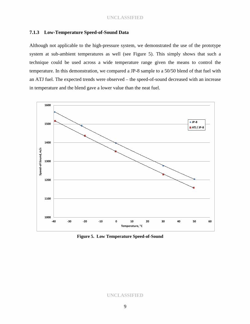
7.1.3 Low-Temperature Speed-of-Sound Data Although not applicable to the high-pressure system, we demonstrated the use of the prototype
system at sub-ambient temperatures as well (see Figure 5). This simply shows that such a
technique could be used across a wide temperature range given the means to control the
temperature. In this demonstration, we compared a JP-8 sample to a 50/50 blend of that fuel with
an ATJ fuel. The expected trends were observed – the speed-of-sound decreased with an increase
in temperature and the blend gave a lower value than the neat fuel.
Figure 5. Low Temperature Speed-of-Sound
1000
1100
1200
1300
1400
1500
1600
-40 -30 -20 -10 0 10 20 30 40 50 60
Spee
d-of
-Sou
nd, m
/s
Temperature, °C
JP-8
ATJ / JP-8
UNCLASSIFIED 9
UNCLASSIFIED
7.2 HIGH PRESSURE APPARATUS 7.2.1 Speed-of-Sound Verification In our first attempts at this technique, we used the known speed-of-sound of water, the known
distance to the target (1.2”), and an approximate value for the speed-of-sound in the metal to
isolate what was believed to be the first stationary echo. Combined with the target echo, this
gave a speed-of-sound for water of 1511.6 m/s (literature 1509.5 @ 30°C, 0.14% error). We then
performed the same measurement on cyclohexane with a result of 1230.6 m/s (literature 1228.7
@ 30°C, 0.15% error).
Since little data exists for speed-of-sound and/or bulk modulus of fuel, we chose to verify the
system further using fluids that are well-documented. The speed-of-sound of water can be found
throughout the literature. We found an interactive site [2] based on a literature reference [3]
useful for tabulating water speed-of-sound data as a function of pressure and temperature. To
confirm the operation of the apparatus on a hydrocarbon fluid, we chose heptane as it is also
well-documented in the literature [4].
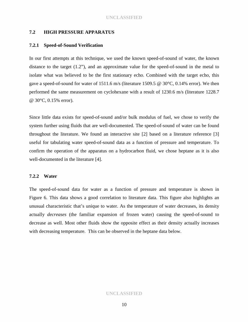
7.2.2 Water The speed-of-sound data for water as a function of pressure and temperature is shown in
Figure 6. This data shows a good correlation to literature data. This figure also highlights an
unusual characteristic that’s unique to water. As the temperature of water decreases, its density
actually decreases (the familiar expansion of frozen water) causing the speed-of-sound to
decrease as well. Most other fluids show the opposite effect as their density actually increases
with decreasing temperature. This can be observed in the heptane data below.
UNCLASSIFIED
10
UNCLASSIFIED
Figure 6. Speed-of-Sound Verification - Water
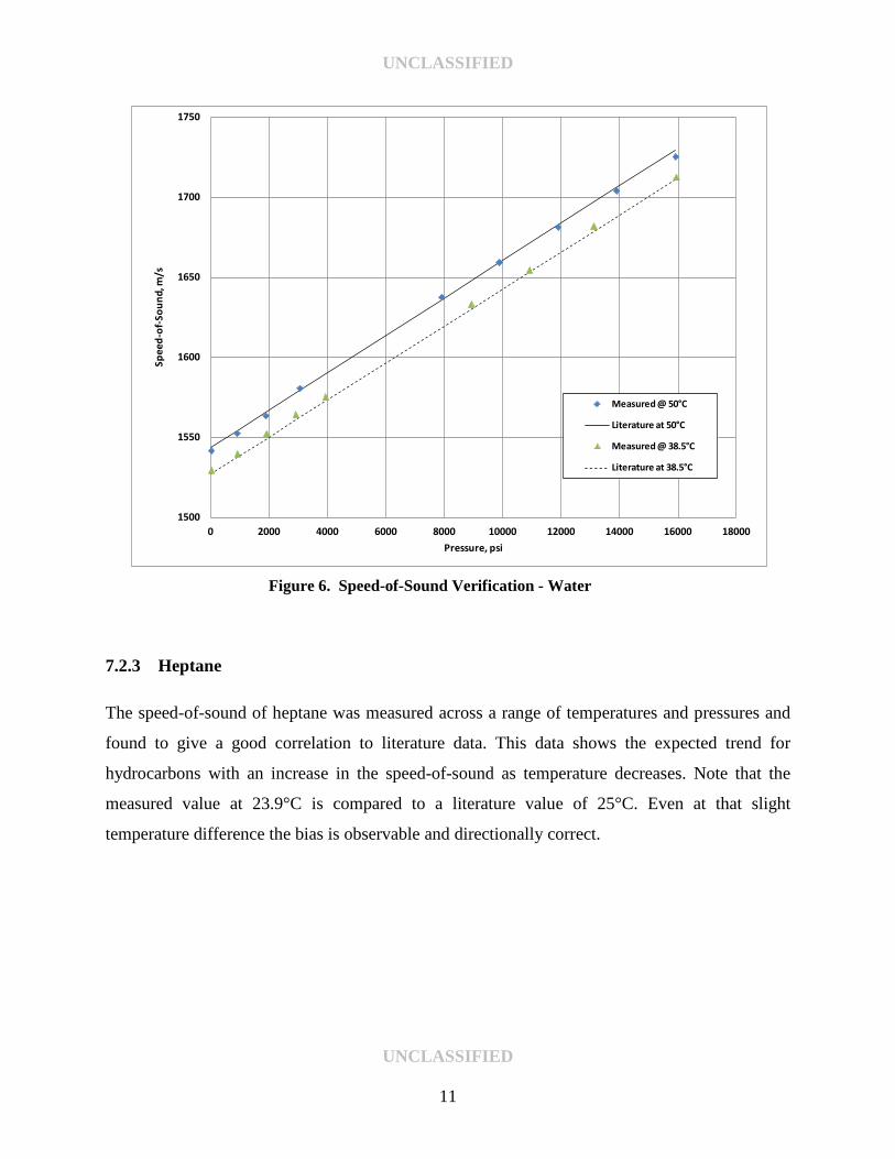
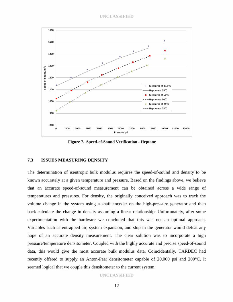
7.2.3 Heptane The speed-of-sound of heptane was measured across a range of temperatures and pressures and
found to give a good correlation to literature data. This data shows the expected trend for
hydrocarbons with an increase in the speed-of-sound as temperature decreases. Note that the
measured value at 23.9°C is compared to a literature value of 25°C. Even at that slight
temperature difference the bias is observable and directionally correct.
1500
1550
1600
1650
1700
1750
0 2000 4000 6000 8000 10000 12000 14000 16000 18000
Spee
d-of
-Sou
nd, m
/s
Pressure, psi
Measured @ 50°C
Literature at 50°C
Measured @ 38.5°C
Literature at 38.5°C
UNCLASSIFIED
11
UNCLASSIFIED
Figure 7. Speed-of-Sound Verification - Heptane
7.3 ISSUES MEASURING DENSITY The determination of isentropic bulk modulus requires the speed-of-sound and density to be
known accurately at a given temperature and pressure. Based on the findings above, we believe
that an accurate speed-of-sound measurement can be obtained across a wide range of
temperatures and pressures. For density, the originally conceived approach was to track the
volume change in the system using a shaft encoder on the high-pressure generator and then
back-calculate the change in density assuming a linear relationship. Unfortunately, after some
experimentation with the hardware we concluded that this was not an optimal approach.
Variables such as entrapped air, system expansion, and slop in the generator would defeat any
hope of an accurate density measurement. The clear solution was to incorporate a high
pressure/temperature densitometer. Coupled with the highly accurate and precise speed-of-sound
data, this would give the most accurate bulk modulus data. Coincidentally, TARDEC had
recently offered to supply an Anton-Paar densitometer capable of 20,000 psi and 200°C. It
seemed logical that we couple this densitometer to the current system.
800
900
1000
1100
1200
1300
1400
1500
1600
0 1000 2000 3000 4000 5000 6000 7000 8000 9000 10000 11000 12000
Spee
d-of
-Sou
nd, m
/s
Pressure, psi
Measured at 23.9°C
Heptane at 25°C
Measured at 50°C
Heptane at 50°C
Measured at 75°C
Heptane at 75°C
UNCLASSIFIED
12
UNCLASSIFIED
8.0 PENDING MODIFICATIONS
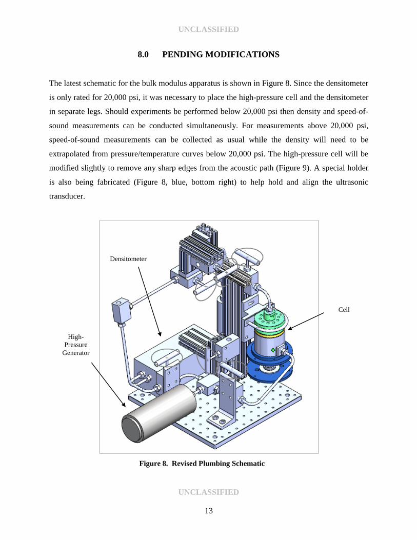
The latest schematic for the bulk modulus apparatus is shown in Figure 8. Since the densitometer
is only rated for 20,000 psi, it was necessary to place the high-pressure cell and the densitometer
in separate legs. Should experiments be performed below 20,000 psi then density and speed-of-
sound measurements can be conducted simultaneously. For measurements above 20,000 psi,
speed-of-sound measurements can be collected as usual while the density will need to be
extrapolated from pressure/temperature curves below 20,000 psi. The high-pressure cell will be
modified slightly to remove any sharp edges from the acoustic path (Figure 9). A special holder
is also being fabricated (Figure 8, blue, bottom right) to help hold and align the ultrasonic
transducer.
Figure 8. Revised Plumbing Schematic
Cell
Densitometer
High-Pressure
Generator
UNCLASSIFIED
13

UNCLASSIFIED
Figure 9. High-Pressure Cell Modifications - Before (left) and After (right)
9.0 CONCLUSIONS
Using a custom-built test rig, speed-of-sound measurements at high temperature and pressure
have been demonstrated successfully and verified against several known fluids and applied to
real-world fuel samples. Using this approach, a preliminary database of bulk modulus data
(atmospheric pressure) was assembled for a wide range of petroleum and synthetic fuels. The test
rig developed under this effort will serve as a good template for future builds. Based on this
research, it was determined that a different approach to measuring density at high
temperature/pressure would be needed to enhance the accuracy of the bulk modulus data under
those conditions.
As of this writing, the high-pressure bulk modulus apparatus is undergoing modifications to
incorporate a high pressure/temperature densitometer. This new design will be the prototype for
the next four units being built under WD 0019 and WD 0021. The modifications to the current
rig are expected to be complete by the end of January 2013 with verification experiments to
begin immediately after. Since this unit has been used as a testbed and undergone several
modifications, it was decided that this unit would remain at SwRI and one of the new units
would be provided to TARDEC. This would ensure that all fielded units are as identical as
possible.
UNCLASSIFIED
14
UNCLASSIFIED
10.0 REFERENCES
1. Dortmund Data Bank, http://www.ddbst.com/
2. http://resource.npl.co.uk/acoustics/techguides/soundpurewater/belogol.html
3. V.A. Belogol'skii, S.S. Sekoyan, L.M. Samorukova, S.R. Stefanov and V.I. Levtsov
(1999), “Pressure dependence of the sound velocity in distilled water,” Measurement
Techniques, Vol 42, No 4, pp 406-413.
4. V. H. Hasanov, “The Speed of Sound of n-Heptane, n-Octane and their Binary Mixtures
at Temperatures T = 293.15 to 523.15 K and Pressures up to 60 MPa,” High
Temperature, 2012, Vol. 50, No. 1, pp. 44–51.
UNCLASSIFIED
15