Embed Size (px)
Citation preview
DEVELOPMENT OF AN ALL-METAL THICK
FILM COST EFFECTIVE METALLIZATION
SYSTEM FOR SOLAR CELLS
BERND ROSS JOSEPH PARKER
BERND ROSS ASSOCIATES 2154 Blackmore Ct. San Diego, CA 92109
May 1980 - January 1983 December 1983
FINAL REPORT
Contractual Acknowledgement
The JPL Low-Cost Silicon Solar Array Project is sponsored by the U.S. Department of Energy and forms part of the Solar Photovoltaic Conversion Program to initiate a major effort toward the development of low-cost solar arrays. This work was performed for the Jet Propulsion Laboratory, California Institute of Technology by agreement between NASA and DOE.
https://ntrs.nasa.gov/search.jsp?R=19840021281 2020-04-21T11:02:23+00:00Z
DRD Line No. SE-6 DOE/JPL-955688-82/10 Distribution Category UC-63
DEVELOPMENT OF AN ALL-METAL THICK
FILM COST EFFECTIVE METALLIZATION
SYSTEM FOR SOLAR CELLS
BERND ROSS JOSEPH PARKER
BERND ROSS ASSOCIATES 2154 Blackmore Ct. San Diego, CA 92109
May 1980 - January 1983
December 1983
FINAL REPORT
Contractual Acknowledgement
The JPL Low-Cost Silicon Solar Array Project is sponsored by the U.S. Department of Energy and forms part of the Solar Photovoltaic Conversion Program to initiate a major effort toward the development of low-cost solar arrays. This work was performed for the Jet Propulsion Laboratory, California Institute of Technology by agreement between NASA and DOE.
" T h i s r e p o r t was p r e p a r e d a s a n a c c o u n t o f work s p o n s o r e d by t h e Un i t ed S t a t e s Government. N e i t h e r t h e Un i t ed S t a t e s n o r t h e U n i t e d S t a t e s Department of Energy , n o r any o f t h e i r employees , n o r any o f t h e i r c o n t r a c t o r s , s u b c o n t r a c t o r s , o r t h e i r employees , makes any w a r r a n t y , e x p r e s s or i m p l i e d , o r assumes any l e g a l l i a b i l i t y o r r e s p o n s i b i l i t y f o r t h e a c c u r a c y , c o m p l e t e n e s s o r u s e f u l n e s s o f any i n f o r - m a t i o n , a p p a r a t u s , p r o d u c t o r p r o c e s s d i s c l o s e d , o r r e p r e s e n t s t h a t i t s u s e would n o t i n f r i n g e p r i v a t e l y owned r i g h t s . "
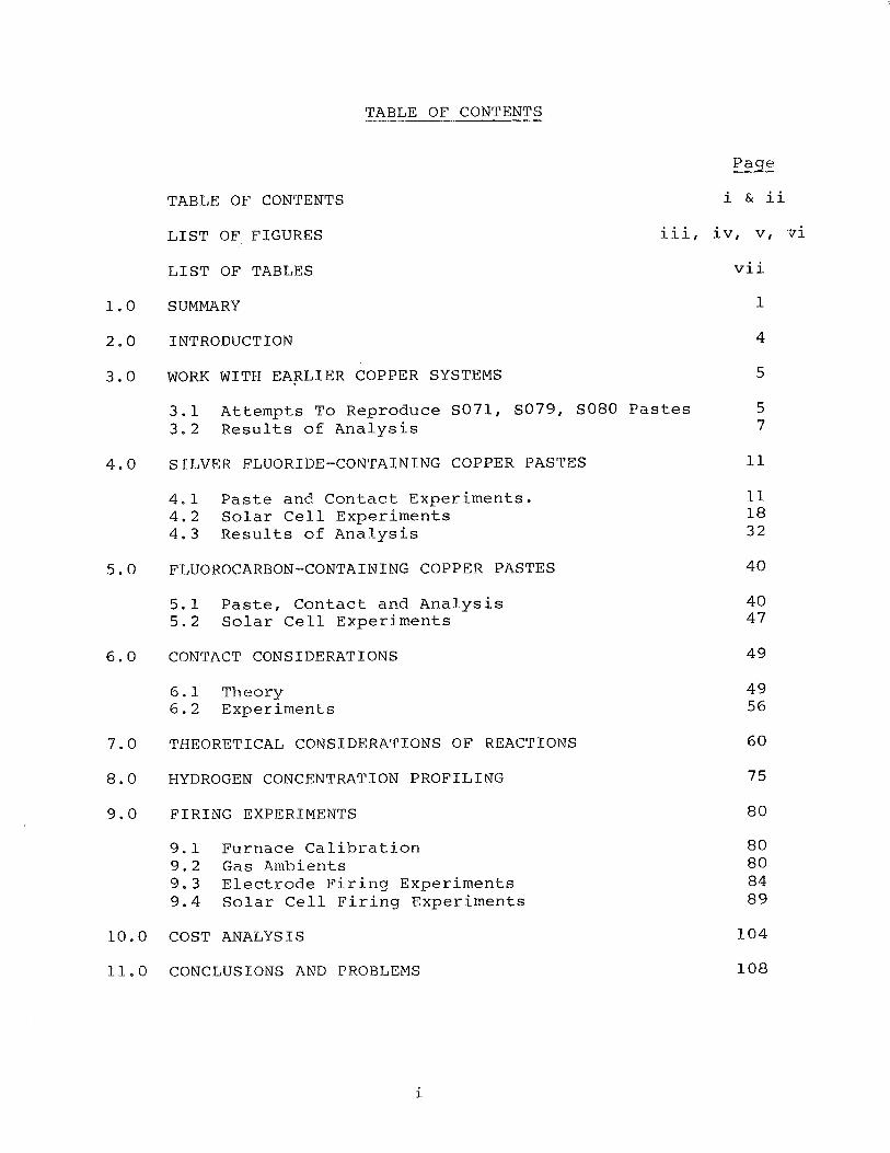
TABLE OF CONTENTS
TABLE OF CONTENTS
Page
i & ii
LIST OF FIGURES iii, iv, v, ui
LIST OF TABLES vii
SUMMARY 1
INTRODUCTION 4
WORK WITH EARLIER COPPER SYSTEMS 5
3.1 Attempts To Reproduce S071, S079, SO80 Pastes 5 3.2 Results of Analysis 7
SILVER FLUORIDE-CONTAINING COPPER PASTES 11
4.1 Paste and Contact Experiments. 4.2 Solar Cell Experiments 4.3 Results of Analysis
FLUOROCARBON-CONTAINING COPPER PASTES 40
5.1 Paste, Contact and Analysis 5 . 2 Solar Cell Experiments
CONTACT CONSIDERATIONS 49
6.1 Theory 6.2 Experiments
THEORETICAL CONSIDERATIONS OF REACTIONS 60
HYDROGEN CONCENTRATION PROFILING 7 5
FIRING EXPERIMENTS 80
9.1 Furnace Calibration 9.2 Gas Ambients 9.3 Electrode Firing Experiments 9.4 Solar Cell Firing Experiments
COST ANALYSIS 104
CONCLUSIONS AND PROBLEMS 108
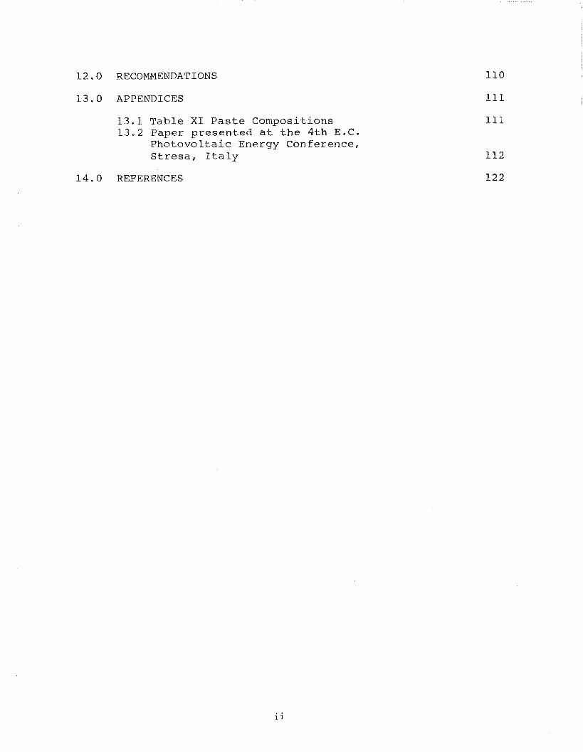
12.0 RECOMMENDATIONS
i 3 . 0 APPENDICES
L3.1 Table XI Paste Compositions 13.2 Paper presented at the 4th E.C.
PhotovoLtaic Energy Conference, Stresa, Italy
14,O REFERENCES
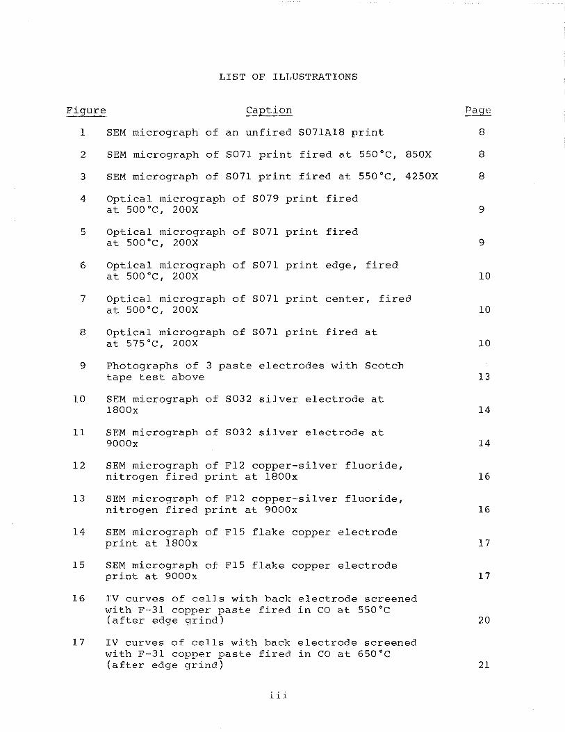
LIST OF ILLUSTRATIONS
Figure Caption
1 SEM micrograph of an unfired S07PA18 print
2 SEM micrograph of SO71 print fired at 550°C, 850X
3 SEM micrograph of SO71 print fired at 550°C, 4250X
4 Optical micrograph of SO79 print fired at 500°C, 200X
5 Optical micrograph of SO71 print fired at 500°C, 200X
6 Optical micrograph of SO71 print edge, fired at 500°C, 200X
7 Optical micrograph of SO71 print center, fired at 500°C, 200X
8 Optical micrograph of SO71 print fired at at 575"C, 200X
9 Photographs of 3 paste electrodes with Scotch tape test above
10 SEM micrograph of SO32 silver electrode at 1800x
11 SEM micrograph of SO32 silver electrode at 9000x
12 SEM micrograph of F12 copper-silver fluoride, nitrogen fired print at 1800x
13 SEM micrograph of F12 copper-silver fluoride, nitrogen fired print at 9000x
14 SEM micrograph of F15 flake copper electrode print at 1800x
15 SEM micrograph of F15 flake copper electrode print at 9000x
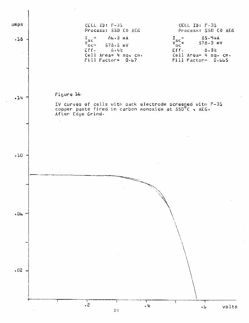
16 IV curves of cells with back electrode screened with F-31 copper paste fired in CO at 550°C (after edge grind)
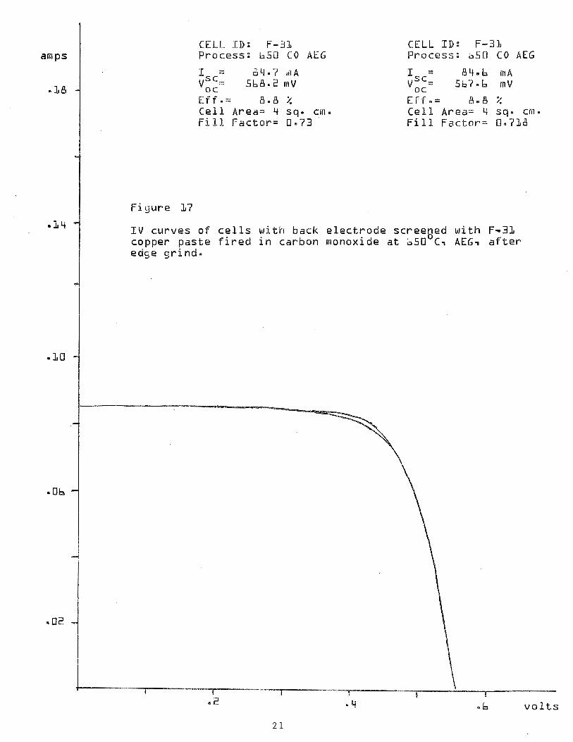
17 IV curves of cells with back electrode screened with F-31 copper paste fired in CO at 650°C (after edge grind)
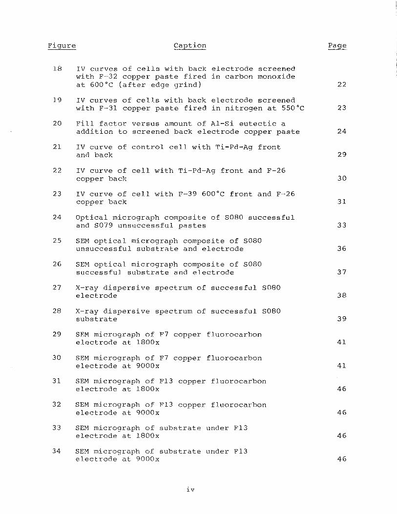
Figure Caption Page
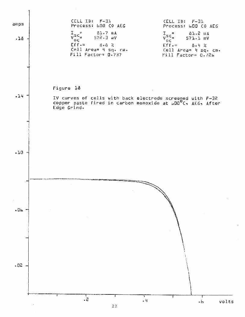
18 IV curves of cells with back electrode screened with F-32 copper paste fired in carbon monoxide at 600°C (after edge grind)
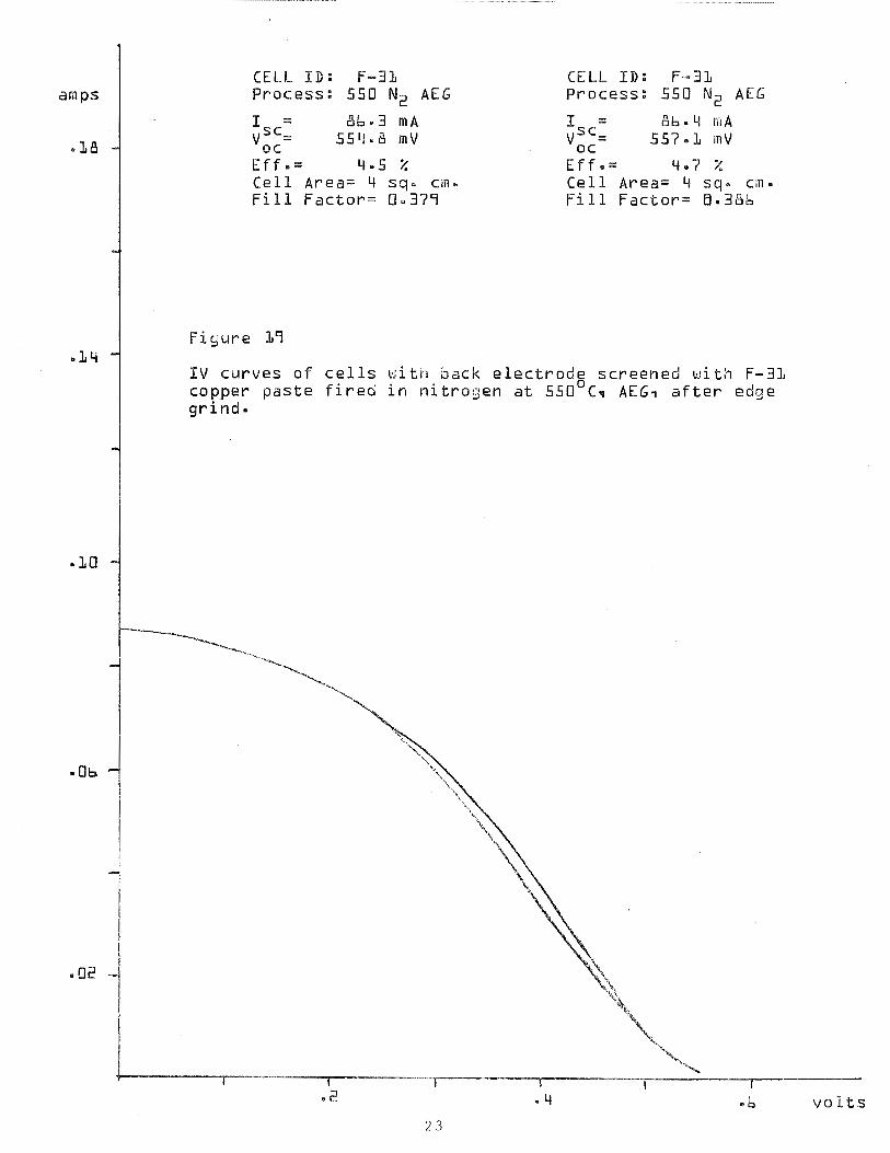
19 IV curves of cells with back electrode screened with F-31 copper paste fired in nitrogen at 550°C
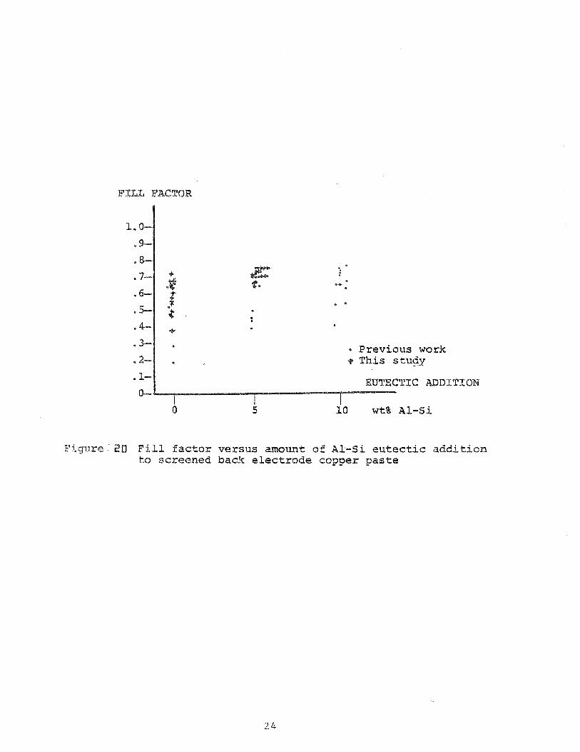
20 Fill factor versus amount of A1-Si eutectic a addition to screened back electrode copper paste
21 IV curve of control cell with Ti-Pd-Ag front and back
22 IV curve of cell with Ti-Pd-Ag front and F-26 copper back
23 IV curve of cell with F-39 600°C front and F-26 copper back
24 Optical micrograph composite of SO80 successful and SO79 unsuccessful pastes
25 SEM optical micrograph composite of SO80 unsuccessful substrate and electrode
26 SEM optical micrograph composite of SO80 successful substrate and electrode
27 X-ray dispersive spectrum of successful SO80 electrode
28 X-ray dispersive spectrum of successful SO80 substrate
29 SEM micrograph of F7 copper fluorocarbon electrode at 1800x
30 SEM micrograph of F7 copper fluorocarbon electrode at 9000x
31 SEM micrograph of F13 copper fluorocarbon electrode at l800x
32 SEM micrograph of F13 copper fluorocarbon electrode at 9000x
33 SEM micrograph of substrate under F13 electrode at 1800x
34 §EM micrograph of substrate under F13 electrode at 9000x
Figure Caption Page
35 I V curve of solar cell with F16 copper- fluorocarbon back contact
36 Contact tunneling resistance versus depletion width
37 Energy level diagram of front contact
38 Energy level diagram of back contact
39 Photograph of test pattern
40 Relation between heat of reaction and activation energy
41 Heats of formation versus n for alkane series Cn H 2n+2
42 Hydrogen profiling by resonant nuclear reaction with nitrogen
43 Preliminary results of hydrogen profiling
44 Tube furnace profile
45 Modified firing profile
46 F-20 copper electrode sintered at 615°C taken at 2000X
47 F-20 copper electrode sintered at 6 1 5 " ~ taken at 10,000X
48 Edge-on view of F-20 copper electrode sintered at 614°C at 675X magnification
49 IV curve of cell with back electrode screened with F-30 copper paste fired at 650°C
50 I V curve of cell with back electrode screened with F-20 copper paste fired at 600°C
51 I V curve of cell witn back electrode screened with F-27 copper paste fired at 600°C
52 F-27 silver fluoride-activated copper paste fired at 600°C, with modified two step process A. Magnification 2000X B . Magnification 10,000X
Figure
53 Comparison of copper paste hydrogen and carbon monoxide firing cycles A. F-27, 650°C, hydrogen, Magnification 2000X B. F-30, 584"C, CO fired, Magnification 2600X
54 F-30, 584"C, carbon monoxide [CO] fired A. Magnification lOOOX B. Edgeview, Magnification 2300X
55 F-30, 584"C, Carbon monoxide fired with a dia- mond scribed scratch at lOOOX magnification
56 I V curve of cell with back electrode screened with F-19 fired at 615°C
57 I V curve of cell with back electrode screened with F-20 copper paste fired at 615°C
58 Circuit-Simulated IV Curves
Page
LIST OF TABLES
Caption
Solar Cell Experiment
Front Contact Paste Compositions
Front and Back Contact Solar Cell Experiment (~eans, Usually 3 Samples)
Composition of Paste F-13
Two Step Firing Process
Selected Heats of Formation
Metal ~xidation/~eduction Data
Copper Paste Compositions
Copper Pastes F-19 and F-20
Cost of Material
Paste Compositions (~ppendix)
Paqe
19
26
1.0 SUMMARY
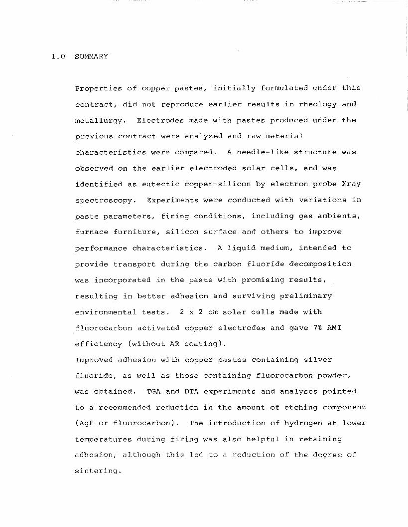
Properties of copper pastes, initially formulated under this
contract, did not reproduce earlier results in rheology and
metallurgy. Electrodes made with pastes produced under the
previous contract were analyzed and raw material
characteristics were compared. A needle-like structure was
observed on the earlier electroded solar cells, and was
identified as eutectic copper-silicon by electron probe Xray
spectroscopy. Experiments were conducted with variations in
paste parameters, firing conditions, including gas ambients,
furnace furniture, silicon surface and others to improve
performance characteristics. A liquid medium, intended to
provide transport during the carbon fluoride decomposition
was incorporated in the paste with promising results,
resulting in better adhesion and surviving preliminary
environmental tests. 2 x 2 cm solar cells made with
fluorocarbon activated copper electrodes and gave 7% AM1
efficiency (without AR coating).
Improved adhesion with copper pastes containing silver
fluoride, as well as those containing fluorocarbon powder,
was obtained. TGA and DTA experiments and analyses pointed
to a recommended reduction in the amount of etching component
( A ~ F or fluorocarbon). The introduction of hydrogen at lower
temperatures during firing was also helpful in retaining
adhesion, although this led to a reduction of the degree of
sintering,
F r o n t c o n t a c t e x p e r i m e n t s were d o n e w i t h s i l v e r f l u o r i d e
a c t i v a t e d p a s t e s o n b a r e s i l i c o n , s i l i c o n o x i d e a n d s i l i c o n
n i t r i d e c o a t e d s i l i c o n wafers. A d h e s i o n o f p a s t e s w i t h AgF
on s i l i c o n n i t r i d e c o a t e d w a f e r s was g o o d , b u t i n d i c a t i o n s
were t h a t a l l c e l l s were s h u n t e d a n d t h e c o n c l u s i o n was t h a t
t h e s e s y s t e m s were u n s u i t a b l e f o r f r o n t c o n t a c t s .
E x p e r i m e n t s w i t h a luminum b a c k s u r f a c e s a n d s c r e e n e d c o n t a c t s
t o t h a t s u r f a c e were b e g u n , A s p e c i a l l o w t h e r m a l m a s s
q u a r t z b o a t was d e s i g n e d and c o n s t r u c t e d . S o l a r c e l l s were
f a b r i c a t e d w i t h s c r e e n e d c o p p e r b a c k e l e c t r o d e s w i t h e f f i c -
i e n c i e s up t o 1 1 . 3 % . Low t e m p e r a t u r e f i r i n g t e n d e d t o r e s u l t
i n S s h a p e d I V c u r v e s . T h i s was a t t r i b u t e d t o a b a r r i e r
fo rmed a t t h e s i l i c o n - c o p p e r i n t e r f a c e , An e l e c t r i c a l
a n a l o g u e c o n s i s t i n g o f a germanium j u n c t i o n b i n d i n g t h e c e l l ,
g a v e a s i m i l a r l y S s h a p e d c u r v e .
A c o o p e r a t i v e e x p e r i m e n t was i n i t i a t e d w i t h W.A. L a n f o r d o f
S.U.N.Y. A l b a n y o n t h e e f f e c t o f h e a t - t r e a t m e n t s i n v a r i o u s
a t m o s p h e r e s o n t h e h y d r o g e n p r o f i l e o f s i l i c o n s u r f a c e s .
C o n t a c t t h e o r y was e x p l o r e d t o d e t e r m i n e t h e r o l e o f v a r i o u s
p a r a m e t e r s o n t u n n e l i n g and c o n t a c t r e s i s t a n c e . A p o s t e r
p a p e r was p r e s e n t e d a t t h e 4 t h E , C . P h o t o v o l t a i c S o l a r
E n e r g y C o n f e r e n c e i n S t r e s a , I t a l y , May 1 9 8 2 . S e v e r a l so l a r
c e l l e x p e r i m e n t s were c a r r i e d o u t w i t h t h e a s s i s t a n c e o f t h e
P r o c e s s R e s e a r c h L a b o r a t o r y o f J P L . D a t a c o n f i r m t h a t t h e
p r e s e n c e o f e u t e c t i c A1-Si a d d i t i o n s a r e b e n e f i c i a l f o r l o w
c o n t a c t r e s i s t a n c e a n d f i l l f a c t o r s i n b a c k c o n t a c t s . I n a
f u r t h e r e x p e r i m e n t c o p p e r p a s t e s w i t h d i f f e r e n t s i l v e r
fluoride additions were utilized as front contacts at two
temperatures. Data shows various degrees of shunting, making
this process/material unlikely for front contacts. Screened
fritted and all metal silver showed promise as contacts to
aluminum back electrode solar cells,
Finally, an experiment was run with carbon monoxide gas used
as the reducing ambient during firing. Excellent adhesion,
sintering and good coppery appearance were obtained.
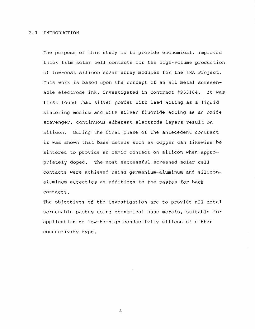
2.0 INTRODUCTION
The purpose of this study is to provide economical, improved
thick film solar cell contacts for the high-volume production
of low-cost silicon solar array modules for the LSA Project.
This work is based upon the concept of an all metal screeen-
able electrode ink, investigated in Contract #955164. It was
first found that silver powder with lead acting as a liquid
sintering medium and with silver fluoride acting as an oxide
scavenger, continuous adherent electrode layers result on
silicon. During the final phase of the antecedent contract
it was shown that base metals such as copper can likewise be
sintered to provide an ohmic contact on silicon when appro-
priately doped. The most successful screened solar cell
contacts were achieved using germanium-aluminum and silicon-
aluminum eutectics as additions to the pastes for back
contacts.
The objectives of the investigation are to provide all metal
screenable pastes using economical base metals, suitable for
application to low-to-high conductivity silicon of either
conductivity type.
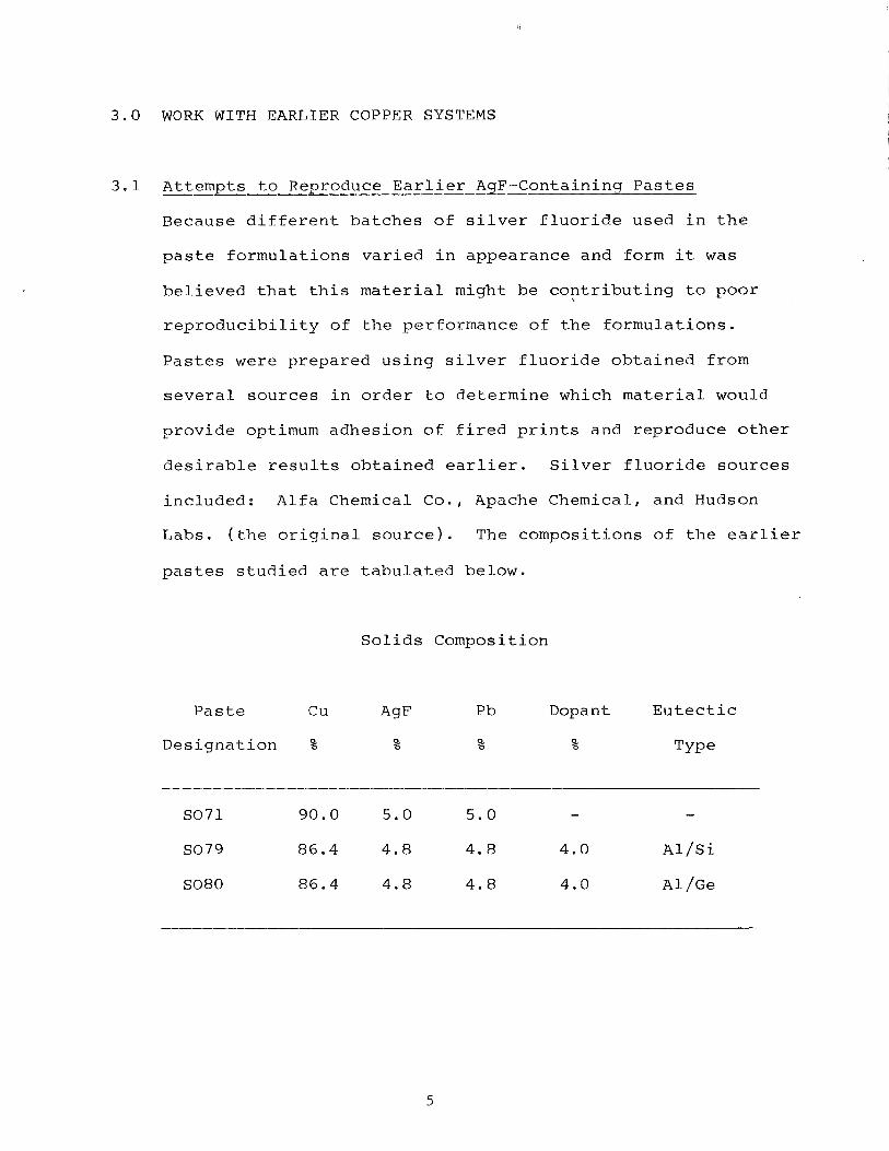
3.0 WORK WITH EARLIER COPPER SYSTEMS
3.1 Attempts to Reproduce Earlier AgF-Containing Pastes
Because different batches of silver fluoride used in the
paste formulations varied in appearance and form it was
believed that this material might be contributing to poor \
reproducibility of the performance of the formulations.
Pastes were prepared using silver fluoride obtained from
several sources in order to determine which material would
provide optimum adhesion of fired prints and reproduce other
desirable results obtained earlier. Silver fluoride sources
included: Alfa Chemical Co., Apache Chemical, and Hudson
Labs. (the original source). The compositions of the earlier
pastes studied are tabulated below.
Solids Composition
Paste Cu A9F Pb Dopant Eutectic
Designation % % % % Type
F i f t e e n d i f f e r e n t b a t c h e s o f SO71 p a s t e were t r i e d . Al though
t h e r e s u l t s v a r i e d , none ach ieved t h e performance o f t h e
o r i g i n a l m a t e r i a l s .
I t was found t h a t copper p a s t e s p r e p a r e d w i t h s i l v e r f l u o r i d e
e x h i b i t e d a marked change i n s u r f a c e c o l o r a s a f u n c t i o n o f
t i m e , i ndependen t o f s t o r a g e c o n d i t i o n s . The s u r f a c e changed
from a reddish-brown c o l o r t o da rk brown and i n extreme cases
becoming a lmos t b l a c k i n appearance . S t i r r i n g , immedia te ly
r e s t o r e d t h e o r i g i n a l c o l o r . P a s t e s c o n t a i n i n g a l l i n g r e d -
i e n t s e x c e p t s i l v e r f l u o r i d e d i d n o t e x h i b i t a c o l o r change.
While t h e e f f e c t o f l i g h t upon s i l v e r h a l i d e s i s w e l l known,
t h i s i s n o t expec ted t o be a f a c t o r , s i n c e p a s t e s w e r e k e p t
i n opaque g l a s s c o n t a i n e r s . T h i s phenomenon had n o t been
obse rved w i t h p a s t e s p r e p a r e d under t h e p r e v i o u s c o n t r a c t .
I t was obse rved t h a t c o n t r o l o f such f i r i n g p a r a m e t e r s a s
atmosphere composi t ion and l o c a l f u r n a c e t e m p e r a t u r e s was
sometimes d i f f i c u l t t o m a i n t a i n .
The f i r i n g p r o c e s s was examined, and f i r i n g exper iments w e r e
c a r r i e d o u t i n t h r e e d i f f e r e n t f a c i l i t i e s : (1) AVX M a t e r i a l s
D i v i s i o n ( fo rming gas c o n s i s t i n g o f 90% n i t r o g e n and 10%
hydrogen) i n a b e l t f u r n a c e , ( 2 ) Bernd Ross A s s o c i a t e s , two
s t e p f i r i n g p r o c e s s ( 5 minu tes n i t r o g e n fo l lowed by 8 m i n u t e s
of hydrogen) i n a q u a r t z t u b e f u r n a c e and ( 3 ) Appl ied S o l a r
Energy C o r p o r a t i o n , two s t e p f i r i n g p r o c e s s i n a q u a r t z t u b e
f u r n a c e .
3.2
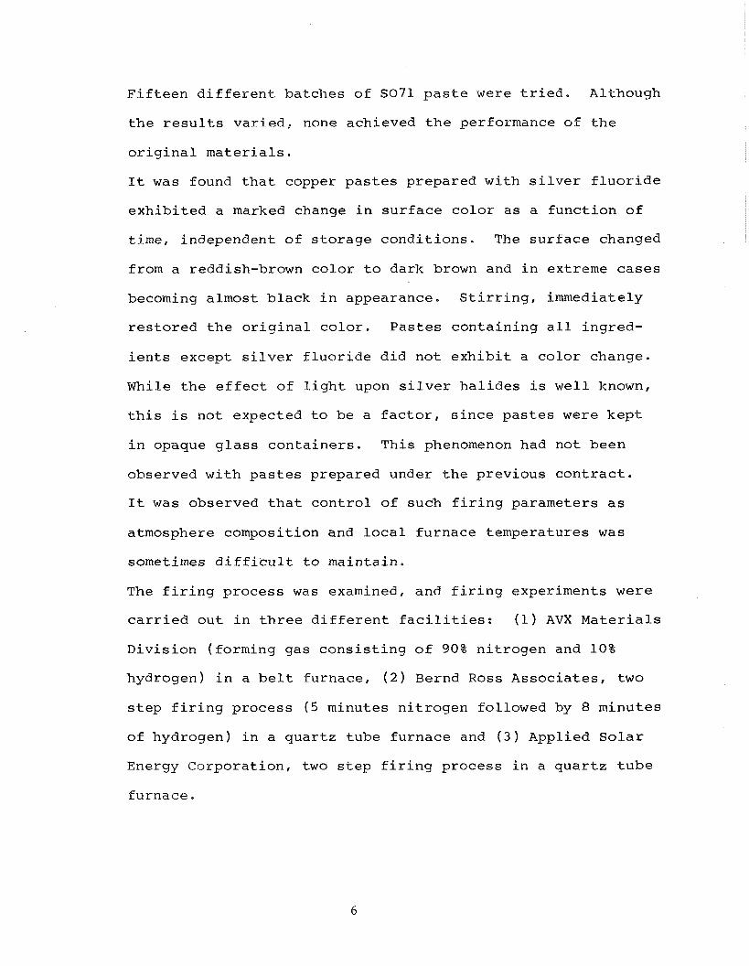
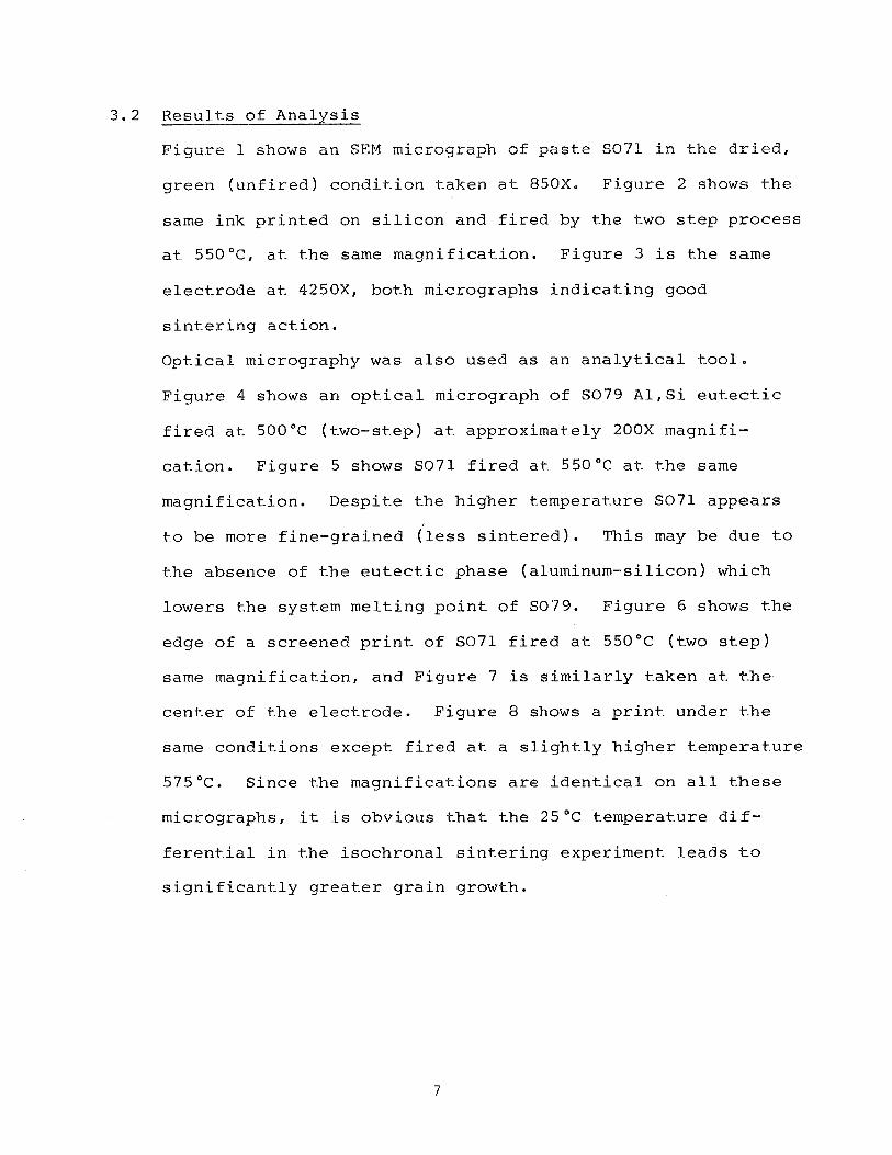
Figure 1 shows a n SEM micrograph of pas te SO71 i n t-he d r i e d ,
green ( u n f i r e d ) condi t ion taken a t 850X. Figure 2 shows t h e
same ink p r i n t e d on s i l i c o n and f i r e d by the two s t e p process
a t 550°C, a t t-he same magnificat-ion. Figure 3 i s t-he same
elect-rode a t 4250X, both micrographs i n d i c a t i n g good
s i n t e r i n g act-ion.
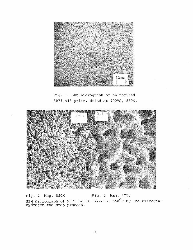
Opt ica l micrography was a l s o used a s an a n a l y t i c a l t o o l .
Figure 4 shows an o p t i c a l micrograph of SO79 A 1 , S i eut-ect-ic
f i r e d at. 500°C (two-step) a t approximat-ely 200X magnifi-
cat-ion. Figure 5 shows S O 7 1 f i r e d a t 550°C at. t h e same
magnification. Despit-e t-he h igher temperat-ure SO71 appears
t-o be more f ine-grained ( l e s s s i n t e r e d ) . This may be due t o
t-he absence of t-he eutect- ic phase (aluminum-silicon) which
lowers t-he system melt ing p o i n t of S079. Figure 6 shows t h e
edge of a screened p r i n t of SO71 f i r e d a t 550°C (two s t e p )
same magnification, and Figure 7 i s s i m i l a r l y t-aken a t t h e
cen te r of t h e e l ec t rode . Figure 8 shows a p r i n t under t h e
same condit ions except f i r e d a t a s l ight - ly h igher temperature
575°C. Since t h e magnificat-ions a r e i d e n t i c a l on a l l t h e s e
micrographs, it i s obvious t h a t t h e 25OC temperature d i f -
f e r e n t i a l i n t h e isochronal s i n t e r i n g experiment l eads t o
s ign i f i can t - ly g r e a t e r g ra in growt-h.
F i g . 1 SEM Micrograph o f an u n f i r e d
Soil-A18 p r i n t , d r i e d a t 900°c, 850X.
F i g . 2 Mag. 850X F i g . 3 Mag. 4250
SEM Micrograph of SO71 p r i n t f i r e d a t 5 5 0 ~ ~ by t h e n i t r o g e n - hydrogen two s t e p p r o c e s s .
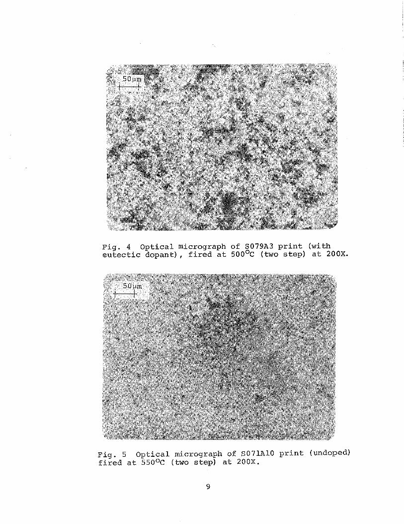
Fig. 4 Op t i ca l micrograph of S079A3 p r i n t (with e u t e c t i c dopant) , f i r e d a t 5 0 0 ~ ~ (two s t e p ) a t 200X.
Fig . 5 Opt ica l micrograph of S071A10 p r i n t (undoped) f i r e d a t 550°c (two s t e p ) a t 200X.
9
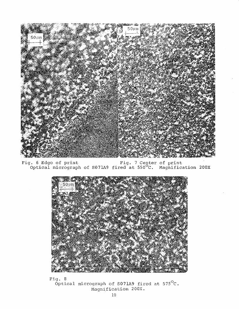
Fig . 6 Edge o f p r i n t F i g . 7 Center of p r i n t O p t i c a l micrograph of S071A9 f i r e d a t 550°C. Magni f ica t ion 200X
F i g . 8 O p t i c a l micrograph of S071A9 f i r e d a t 5 7 5 O ~ .
Magn i f i ca t ion 2 0 0 X , 10
4.0 SILVER FLUORIDE-CONTAINING COPPER PASTES
4.1 Paste and Contact Experimentation S i l v e r F luor ide
Most of t h e i n i t i a l copper pas tes of the p resen t group ( F
s e r i e s ) gave poor r e s u l t s , with powdery su r faces ind ica t ing
inadequate s i n t e r i n g and i n s u f f i c i e n t adhesion. Figure 9
shows a microphotograph of number of t e s t p ieces of e a r l y
e lec t rode pas te samples. The Scotch tape s t r i p f o r t h e
adhesion t e s t i s displayed above each sample. Pastes a r e ;
from top t o bottom, F-5 (AgF), F-6 (AgF) and F-7
(f luorocarbon) and t h e f i r i n g temperatures a r e , from l e f t t o
r i g h t , 525"C, 550°C, 575"C, 600°C, and 625°C. In some cases
t h e e n t i r e e l e c t r o d e l i f t e d from t h e s u b s t r a t e .
Since adhesion of t h e copper /s i lver f l u o r i d e pas tes was so
poor, it was decided t o t r y some of t h e s i l v e r pas tes of t h e
previous group ( S O s e r i e s ) containing 2 % s i l v e r f l u o r i d e and
which had given acceptable adhesion and sc ra tch r e s i s t a n c e .
S i l i c o n wafers were screened with s i l v e r ink SO32 and f i r e d
a t 550°C i n a i r and by t h e two-step process . Excel lent
adhesion was obtained i n t h e case of a i r - f i r e d s i l v e r
e l ec t rodes . S i l v e r e l ec t rodes f i r e d i n hydrogen separated
from the s u b s t r a t e s spontaneously. The s i l v e r e l ec t rodes
removed from the s u b s t r a t e s had good sheet i n t e g r i t y and
s t r eng th .
The structure of the silver electrode sheets is shown in
Figures 10 and 11 at 1800x and 9000x respectively. The
structure is so well interlocked as to appear oversintered.
The smaller circular dots are believed to be a segregated
metallic lead phase.
Previously we suspected interference of the hydrogen with the
etching action of the fluorine component. The bonds at the
silicon surface may be more attractive to hydrogen than other
atomic species, based upon the silicon-hydrogen bond strength
(71.3 ~cal/mole), lor Silver fluoride content of the copper
pastes ranged from 1.1 wt% to 3.7 wt%. Smaller quantities of
silver fluoride were used after an analysis by Dr. Joseph
Parker, which pointed to spoiler reactions resulting from the
presence of silver fluoride (Section 7.0).
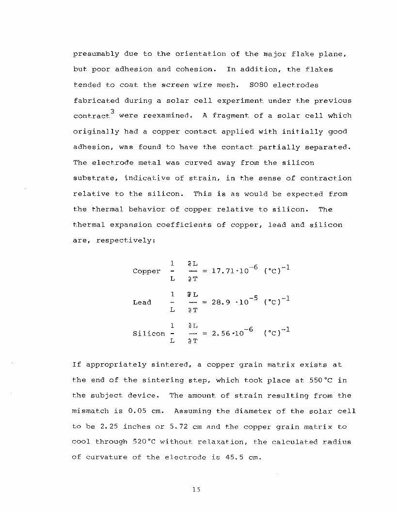
The paste containing the smallest amount of silver fluoride
gave the best results to date. One test sample fired in
nitrogen at 550°C passed the Scotch tape test (~12). Figures
12 and 13 show SEM micrographs of electrodes resulting from
this experiment (shown at 1800x and 9000x, respectively)
while the sintering action appears to be moderately good, the
surface texture, suggests an oxide coating (particularly at
the higher magnification) . One further variation utilized copper flake for the major
constituent in paste F15. Electrodes fired at 550°C by the
two-step process are shown as SEM micrographs in Figures 14
and 15. Magnifications are 1800x and 9000x, respectively.
The electrodes resulting from this had good metallic sheen,
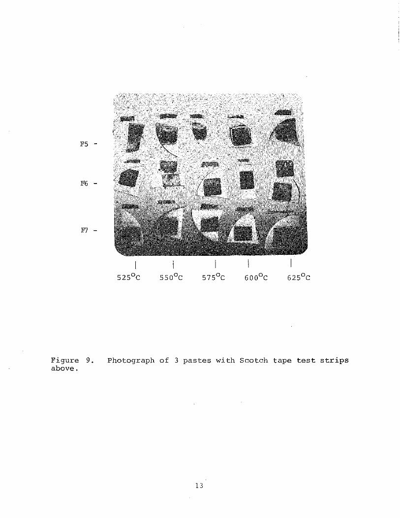
F i g u r e 9. Photograph o f 3 p a s t e s w i t h S c o t c h t a p e tes t s t r i p s above.
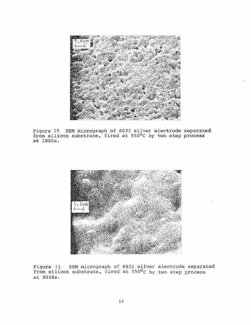
Figure 10 SEM micrograph of SO32 s i l v e r e l e c t r o d e s e p a r a t e d Erom s i l i c o n s u b s t r a t e , f i r e d a t 5 5 0 ~ ~ by two s t e p p roces s a t 1800x.
F igu re 11 SEM micrograph of SO32 s i l v e r e l e c t r o d e s e p a r a t e d from s i l i c o n s u b s t r a t e , f i r e d a t 5 5 0 ~ ~ by two s t e p p roces s a t 9000x.
presumably due t o t h e or ient-at ion of t h e major f l a k e p lane ,
but poor adhesion and cohesion. In add i t ion , t h e f iakes
tended t o c o a t the screen wire mesh. SO80 e lec t rodes
f ab r i ca ted during a s o l a r c e l l experiment under t.he previous
cont rac t3 were reexamined. A fragment of a s o l a r c e l l which
o r i g i n a l l y had a copper contac t appl ied with i n i t - i a l l y good
adhesion, was found t-o have t-he contac t p a r t i a l l y separa ted .
The e lec t rode metal was curved away from the s i l i c o n
s u b s t r a t e , i n d i c a t i v e of s t r a i n , i n t h e sense of con t rac t ion
r e l a t i v e t-o t h e s i l i c o n . This i s as would be expected from
t h e thermal behavior of copper r e l a t i v e t o s i l i c o n . The
thermal expansion c o e f f i c i e n t s of copper, lead and s i l i c o n
a r e , r e spec t ive ly :
1 a L Copper - - = 17.71.10 -6 ( O c 1-1
1 2L Lead - -.- = 28.9 410 -5 ( O c 1 -1
1 a L S i l i c o n - --- = 2.56-10 -6 ( o c 1-1
I f appropriat-ely s i n t e r e d , a copper g r a i n matrix e x i s t s a t
t-he end of t-he s i n t e r i n g s t e p , which took p lace a t 550°C i n
t-he sub jec t device. The amount of s t r a i n r e s u l t i n g from t h e
mismatch i s 0.05 cm. Assuming t h e diameter of t h e s o l a r c e l l
t o be 2.25 inches o r 5.72 crn and the copper g r a i n matr ix t o
cool t-hrough 520 O C wit-hout r e l axa t ion , t h e ca lcu la ted r a d i u s
of curvature of the e l ec t rode i s 45.5 cm.
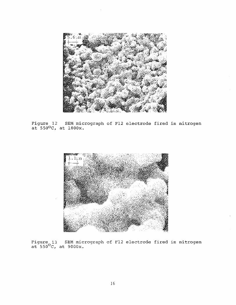
Figure 1 2 SEM micrograph of F12 e l e c t r o d e f i r e d i n n i t rogen a t 550°c, a t 1800x.
Figure 1 3 SEM micrograph of F12 e l e c t r o d e f i r e d i n n i t rogen a t 550°c, a t 9000x.
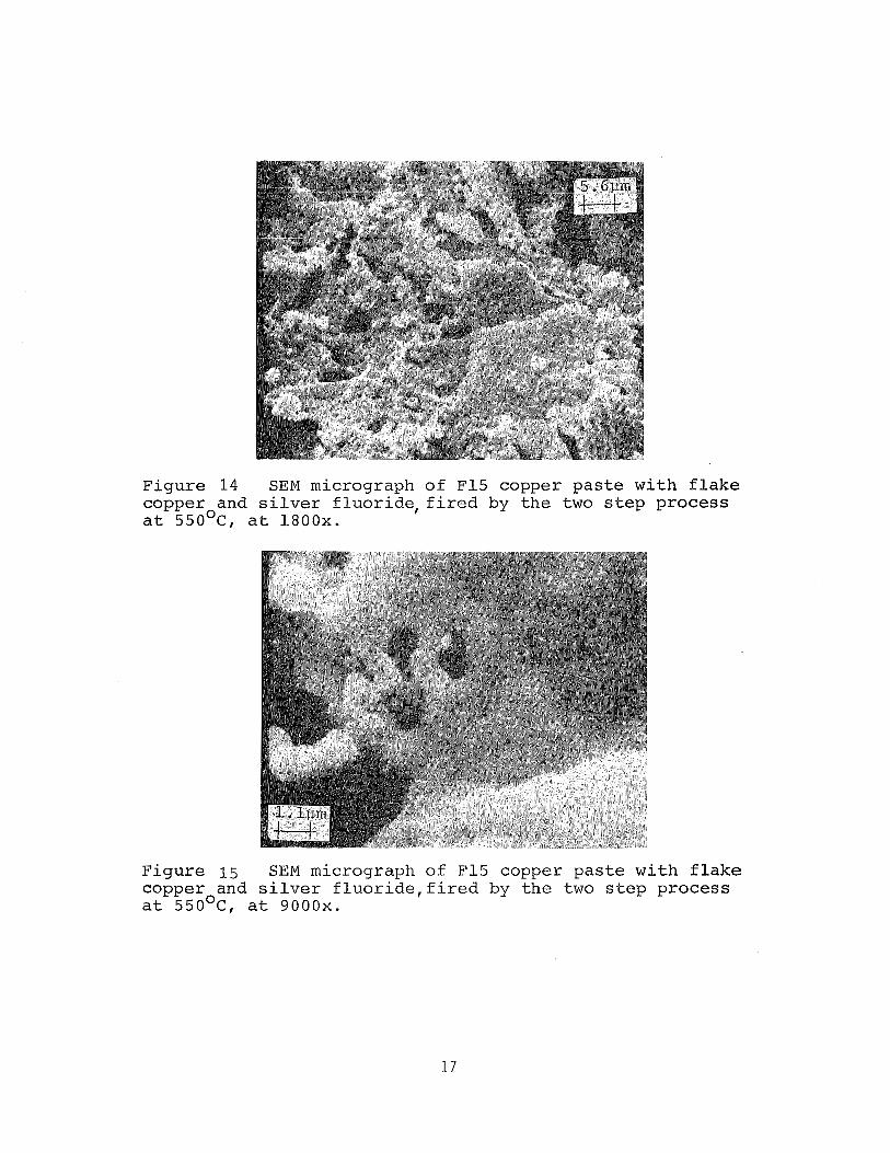
Figure 1 4 SEM micrograph of F15 copper pas t e wi th f l a k e copper and s i l v e r f l u o r i d e l f i r e d by t h e two s t e p process a t 550°c, a t 1800x.
F igure 15 SEM micrograph of F15 copper p a s t e wi th f l a k e copper and s i l v e r f l u o r i d e , f i r e d by t h e two s t e p process a t 550°c, a t 9000x.
While t h e i n i t i a l adhesion of SO80 pas te was e x c e l l e n t it
appears t h a t longterm s to rage (approximately 18 months)
caused c a t a s t r o p h i c s p a l l i n g of t h e copper e l ec t rode , While
t h e causes f o r t h i s a r e not known, it may be t h a t t h e
r e l a t i v e l y t h i c k and densely s i n t e r e d e lec t rode could not
withstand ambient thermal excursions,
4.2 Solar Ce l l Experiments
The s o l a r c e l l experiments were done with pas tes SO71 and
SO93 involving t h e f r o n t contac t . The f i r s t of these
u t i l i z e d wafers with various junction depths and s i l i c o n
oxide coat ings . The experimental parameters were descr ibed
i n d e t a i l i n re ference 4. Due t o poor adhesion no e l e c t r i c a l
da ta could be obtained.
In a second experiment, p a s t e F20 was u t i l i z e d on c e l l s with
a junction depth of approximately 0.5 p m and an Si02 a n t i -
ref lect- ion coat ing . A s i n t h e f i r s t experiment the con tac t
was screened on t h e AR coat ing with t h e i n t e n t of f i r i n g
through. The con tac t adhesion problem was again s u f f i c i e n t
t o prevent t h e t ak ing of s o l a r c e l l measurement da ta .
A s o l a r c e l l experiment was c a r r i e d out u t i l i z i n g F-31 and
F-32 copper p a s t e s . De ta i l s of t h i s experiment a r e given i n
Table I and Figures 16 through 19. The major f a c t o r i n t h i s
experiment was t h e comparison of e l ec t rodes containing 8 w t .
"sF-31) and 5 w t . % (F-32) ~ l / S i eu t -ec t i s . The ni t rogen
f i r e d c e l l I V curve shows t h e c h a r a c t e r i s t i c t y p i c a l of a
Schottky b a r r i e r i n s e r i e s with t h e P N junction.
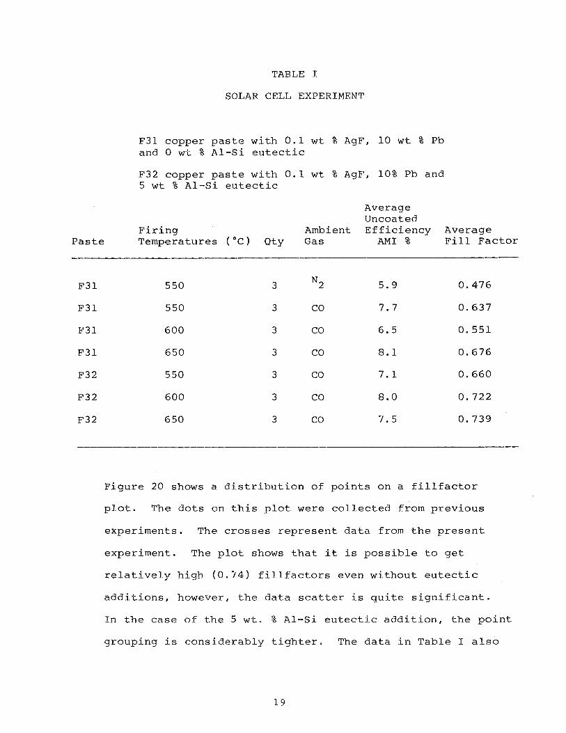
TABLE I
SOLAR CELL EXPERIMENT
F31 copper paste with 0.1 wt % AgF, 10 wt % Pb and 0 wt % A1-Si eutectic
F32 copper paste with 0.1 wt % AgF, 10% Pb and 5 wt % A1-Si eutectic
Average Uncoated
Firing Ambient Efficiency Average Paste Temperatures ( "c) Qty Gas AM1 % Fill Factor
Figure 20 shows a distribution of points on a fillfactor
plot. The dots on this plot were collected from previous
experiments. The crosses represent data from the present
experiment. The plot shows that it is possible to get
relatively high ((3.74) fillfactors even without eutectic
additions, however, the data scatter is quite significant.
In the case of the 5 wt. % A1-Si eutectic addition, the point
grouping is considerably tighter. The data in Table I also
amps
0 L8
ae
02
CELL ID: F-31 P rocess : 550 C0 AEG
- ;SC- bb 6 3 tila
oc= 548.5 1nV E f f . 6 e L i % C e l l area^ 4 s q s CIiI-
F i l l F a c t o r = B.b7
CELL ID: F - 3 ~ P rocess : 5 5 0 C O AEG
I = 135~9ii1A s c -
Voc- 5 7 8 . 3 m V E f f * 8.3% C e l l Area= 4 s q - cm. F i l l F a c t o r = 0.bb5
I V c u r v e s o f c e l l s w i t h oack e l e c t r o d e s c r e e g e d w i t n F -31 coppe r p a s t e f i r e d i n c a r b o n monox ide a t 550 C -, AEG, A f t e r Edge G r i n d .
\
\ '\
'\ \ 1 \
. S f e 0 v o l t s
2 0
amps
.La
.LO
.Oh
CELL ID: F-31 P rocess : b50 C O AEG
1 = 6 4 . 7 islA "= 568.2 mV
v o c E f f a = B - 4 %; C e l l Area= 4 s q . cin. F i l l F a c t o r = 8.73
CELL ID: F-31 P rocess : 05Q C O AEG
% = 841b m A "= 5b7.6 rnV
v o c E f f .= 4.8 % C e l l Area= 4 s q - cr11. F i l l F a c t o r = 0.7LB
F i g u r e 37
I V c u r v e s o f c e l l s w i t h back e l e c t r o d e s c r e e g e d with F-3L copper p a s t e f i r e d i n c a r b o n monox ide a t b50 C, AEG, a f t e r edse g r i n d .
CELL ID: F-31 P r o c e s s : LBO CO BEG
~ f f .= a.8 z C e l l Area= 4 sq. cm. F i l l F a c t o r = 0.737
CELL ID: F-31 P r o c e s s : bBO C0 AEG
I = BL.2 rnA VSC=
o c 57L.E IIIV
E f f a = 8.4 % C e l l Area= 4 sq . cm. F i l l F a c t o r = D8?2b
F i g u r e 1 8
I V c u r v e s o f c e l l s w i t h b a c k e l e c t r o d e s c r e e g e d w i t h F-32 c o p p e r p a s t e f i r e d i n c a r b o n m o n o x i d e a t bOO Cl AEGl A f t e r Edse G r i n d .
amps 1 CELL ID: F - 3 1 P r o c e s s : 5 5 0 Nz AEG
I = Zb.3 m A v s = =
oc 551-1-8 m V
E f f . = 1-1.5 % C e l l A rea= 4 sq . cne F i l l F a c t o r = 0.379
CELL ID: F - 3 1 P r o c e s s : 5 5 0 N2 A E G
I = 6b.4 r;iA s c -
v o c - 557 0 % 91V
E f f .= 4.7 % C e l l A rea= 4 sq. cm- F i l l F a c t o r = 8.39b
F i g u r e L9
I V c u r v e s o f c e l l s w i t n hack e l e c t r o d g s c r e e n e d w i t h F-3% copper p a s t e f i r e d i n n i t r o g e n a t 550 C1 AEG, a f t e r edge g r i n d .
FILL FACTOR
* *
*
r
- Previous work + This study
TIC ADDITION
0 5 10 wt% Al-Si
Figure 263 Fill factor versus amount of X I - S i eutectic addition to screened back electrode copper paste
indicates that the higher temperatures give generally better
contacts and fillfactors.
SEM studies on F32 and F31 fired copper pastes suggested poor
sintering on the aluminum-silicon containing paste F32.
While the A1-Cu phase diagram is complex, there is no
indication of an intermetallic comnpound formation. F31
showed normal sintering behavior.
Silver fluoride from two sources was utilized. Type "H"
silver fluoride, packed in a plastic bottle appeared quite
wet, with visible liquid moisture in evidence. Melting
occurred at approximately 300°C (melting point for dry
material is approximately 4 3 5 " ~ ) for "H" material,
accompanied by bubbling and after reaction to metallic silver
a glassy residue was in evidence. Type "A" silver fluoride,
packed in a plastic bag within a glass jar, showed
considerably less moisture, however, grain agglomeration
indicated a moisture problem still exists. Type "A" material
melted closer to the published melting point, and no macro-
scopic amounts of residue were seen. SEM micrography showed
evidence of the existence of small amounts of glassy material
for type A silver fluoride also.
One may conclude that the use of silver fluoride in pastes
requires careful evaluation of source material, for initial
moisture content. Further, extreme care must be exercised to
maintain the silver-fluoride powder in a dry state, by
maintaining the material in a desiccated atmosphere and
allowing minimum exposure to ambient atmospheres during
handling opera t ions .
Once t h e ma te r i a l has been added t o a paste-containing
vehic le , these procedures may be relaxed, a s t h e vehic le
coaking provides some p ro tec t ion .
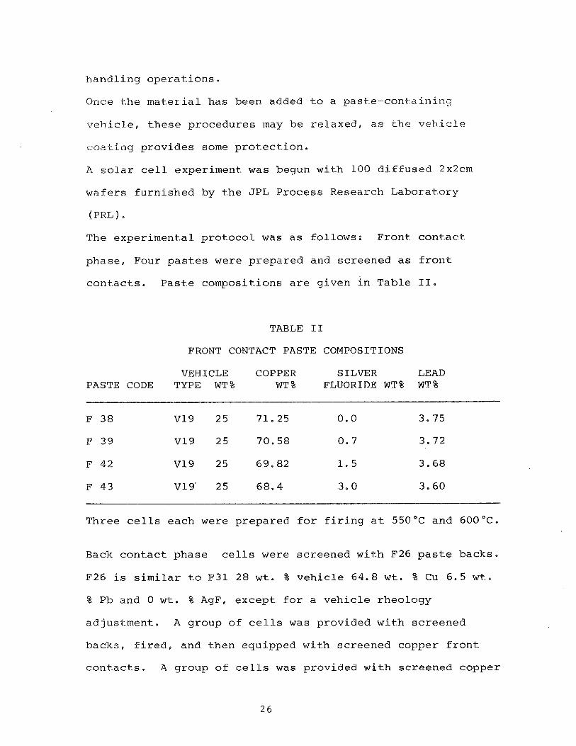
A s o l a r c e l l experiment was begun with 100 d i f fused 2x2cm
wafers furnished by the JPL Process Research Laboratory
(PRL ) . The experimental protocol was a s follows: Front con tac t
phase, Four p a s t e s were prepared and screened a s f r o n t
con tac t s . Pas te compositions a r e given i n Table 11.
TABLE I1
FRONT CONTACT PASTE COMPOSITIONS
VEHICLE COPPER SILVER LEAD PASTE CODE TYPE WT% WT % FLUORIDE WT% W T %
Three c e l l s each were prepared f o r f i r i n g a t 550°C and 600°C.
Back contac t phase c e l l s were screened with F26 p a s t e backs.
F26 i s s i m i l a r t o F31 28 w t . % vehic le 64.8 w t . % Cu 6.5 w t .
% Pb and 0 w t . % AgF, except f o r a vehicle rheology
adjustment, A group of c e l l s was provided with screened
backs, f i r e d , and then equipped with screened copper f r o n t
con tac t s . A group of c e l l s was provided with screened copper
f r o n t contac ts only, t o be metal l ized with titaninurn-
pal iadium-si lver (Ti-Pd-Ag) backs by J P i PRL. A group of
c e l l s with an oxide l aye r of approximately 10008 was provided
with screened copper f r o n t contac ts only, t o be meta l l ized
with Ti-Pd-Ag backs by J P L PRL.
A group of c e l l s was provided with screened copper back
contac ts only, t o be metal l ized with Ti-Pd-Ag by J P L PRL.
A group of wafers was returned t y J P L PRL f o r f r o n t and back
Ti-Pd-Ag m e t a l l i z a t i o n a s con t ro l c e l l s .
During and a f t e r f i r i n g it was not iced t h a t adhesion was
s t i l l a problem, p a r t i c u l a r l y on f r o n t contac ts providing a
reduced number of c e l l s f o r f u r t h e r processing and f i n a l
t e s t i n g .
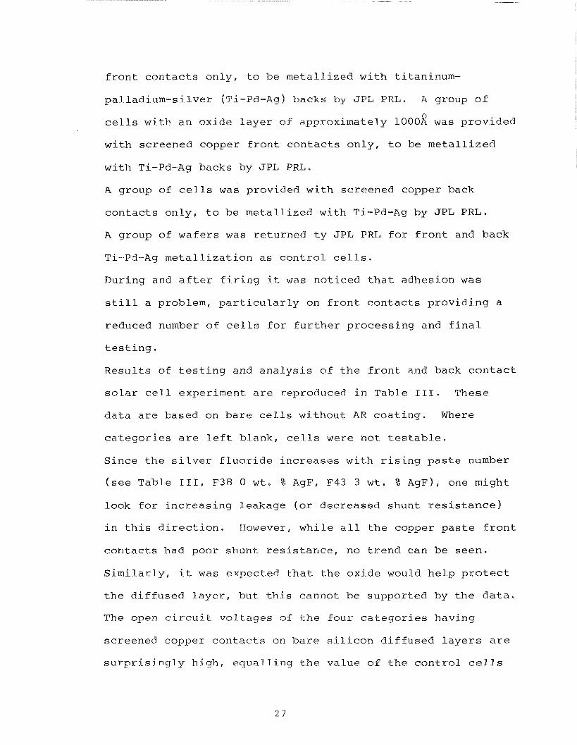
Resul ts of t e s t i n g and a n a l y s i s of t h e f r o n t and back c o n t a c t
s o l a r c e l l experiment a r e reproduced i n Table 111. These
da ta a r e based on bare c e l l s without AR coa t ing . Where
ca tegor ies a r e l e f t blank, c e l l s were not t e s t a b l e .
Since t h e s i l v e r f l u o r i d e increases with r i s i n g p a s t e number
( s e e Table 111, F38 0 w t . % AgF, F43 3 w t . % AgF), one might
look f o r increas ing leakage ( o r decreased shunt r e s i s t a n c e )
i n t h i s d i r e c t i o n . However, while a l l t h e copper pas te f r o n t
con tac t s had poor shunt r e s i s t a n c e , no t r end can be seen.
S imi la r ly , it was expected t h a t the oxide would h e l p p r o t e c t
t h e d i f fused l a y e r , but t h i s cannot be supported by t h e d a t a .
The open c i r c u i t vol tages of t h e four ca tegor ies having
screened copper contac-ts on ba re s i l i c o n d i f fused l a y e r s a r e
s u r p r i s i n g l y h igh : equal l ing t h e value of t h e con t ro l c e l l s
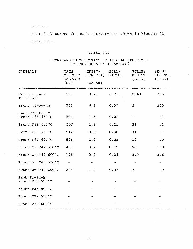
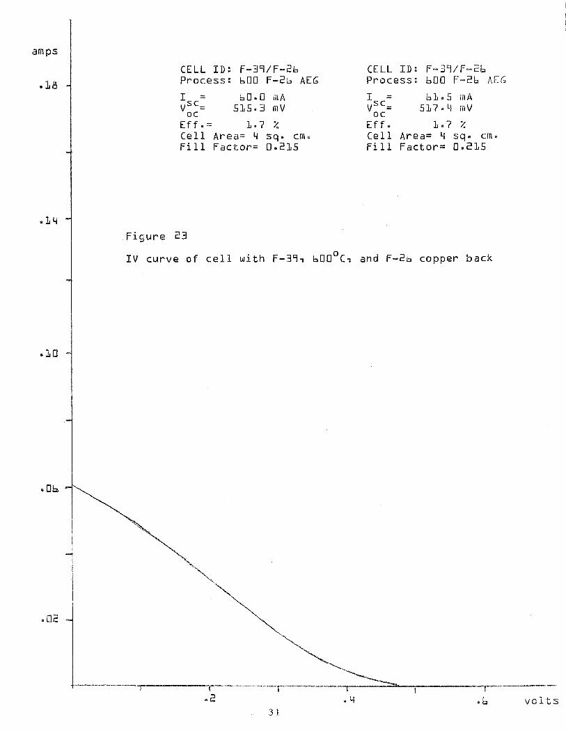
T y p i c a l I V c u r v e s fo r each ca t ego ry are s h o w n i n F i g u r e s % I
through 2 3 .
TABLE I11
FRONT AND BACK CONTACT SOLAR C E L L EXPERIMENT (MEANS, USUALLY 3 SAMPLES)
CONTROLS OPEN E F F I C - F I L L - S E R I E S SHUNT C I R C U I T I E N c Y ( % ) FACTOR R E S I S T . R E S I S T . VOLTAGE ( o h m s ) ( o h m s ) (mV> ( n o A R )
F r o n t & B a c k 507 T i - P d - A g
F ron t T i - P d - A g 5 2 1
B a c k F 2 6 6 0 0 ° C F r o n t F38 5 5 0 ° C 504
F r o n t F38 6 0 0 ° C 5 0 7
F r o n t F39 5 5 0 ° C 5 1 2
F ron t F39 6 0 0 ° C 506
F r o n t O x F 4 2 5 5 0 ° C 430
F r o n t O x F 4 2 6 0 0 " ~ 196
F r o n t O x F43 5 5 0 ° C -
F r o n t O x F43 6 0 0 ° C 2 8 5
B a c k T i - P d - A g F r o n t F38 5 5 0 ° C -
Fron t F38 6 0 0 ° C -
F r o n t F39 5 5 0 ° C -
F r o n t F39 6 0 0 ° C -
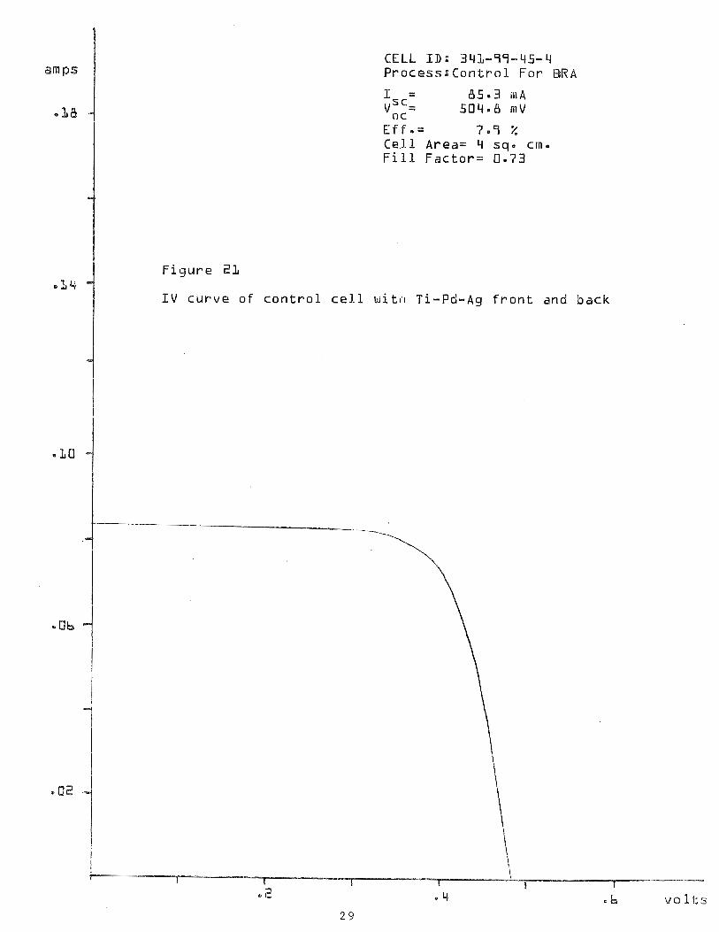
CELL ED: 343-79-45-4 P r o c e s s : C o n t r o l F o r BRA
E f f .= 7.9 % C e l l A rea= 4 sq. cn. F i l l F a c t o r = 0.73
F i g u r e 211
I V c u r v e o f c o n t r o l c e l l w i t n T i -Pd-Ag f r o n t and back
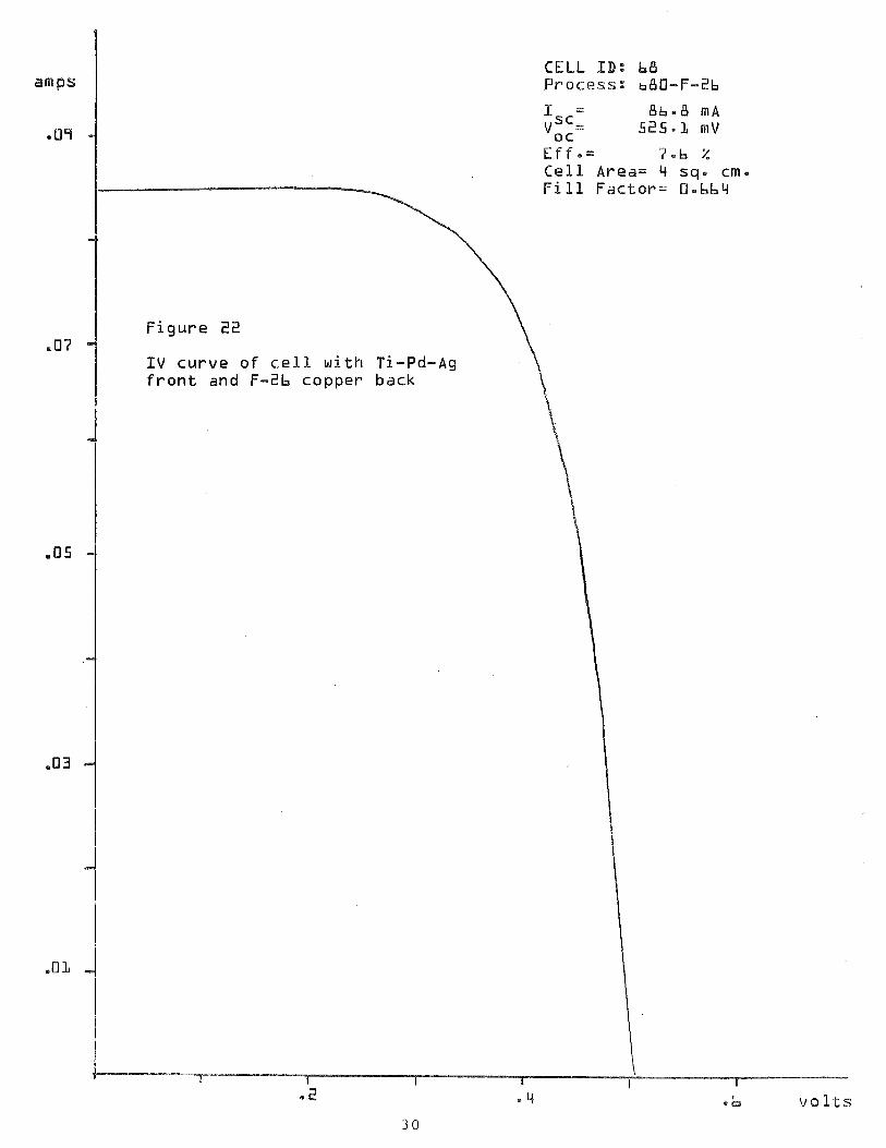
CELL ID: b8 amps P r o c e s s : b80-F-26
1 = 8b.8 M A -09 v,":= 525.L m V
E f f . = 7.b 2 Cel l A r e a = 4 sq. cm. F i l l F a c t o r = O-bb4
.07 I V c u r v e o f c e l l w i t h Ti-Pd-Ag f r o n t a n d F-2b c o p p e r b a c k
.05
.Q3
.O L
3 0
amps
.fit3
as
CELL ID: F-39/F-Zb Process: LOO F-2b AEG
I = b0.0 KIA sc-
voc- 535.3 m V
E f f e = 1 - 7 % C e l l Area= 4 sq. crn. F i l l F a c t o r = 0.215
CELL ID: F-SS/F-2b Process : b00 F-26 AEG
E f f . 1.7 % C e l l Area= 4 sq. em. F i l l F a c t o r = 0.215
F i ~ u r e 23
I V c u r v e o f c e l l w i t h F-39, bOOO~, and F-2b copper back
4 . 3
r A simple Scotch tape adherence test was devised to allow
crude, instant evaluation of the results of electrode tests.
Likewise a scratch test, that allows comparative analysis of
the electrode strength, was initiated.
During the present reporting period a number of pastes
manufactured previously with varying parameters were
analyzed. The manual screening was improved to allow
reproducible registration and constant snapoff distance
(.012"). The tube furnace was profiled again with the
standard platinum - platinum plus 13% rhodium thermocouple
and a digital microvoltmeter. An error was found on the
furnace chromel-alumel thermocouple. Spot checks with
platinum reference thermocouple were made routine on all
firings. Some variation in firing was found, leading to some
suspicion of potential downstream sample contamination from
contaminated furnace tube, gas or exudant from upstream
samples.
Problems with electrode prints were:
1) Lack of adhesion, possibly due to inadequate reduction of
oxide, (silicon surface and powder grain surfaces) or
tying up of dangling surface bonds by hydrogen atoms.
2) Poor sintering due to inadequate liquid transport
(discussed in Section 5.1).
Samples of characterization attempts of successful and unsuc-
cessful pastes are shown in the following figures. Figure 24
depicts four optical photomicrographs of successful SO80 sub-
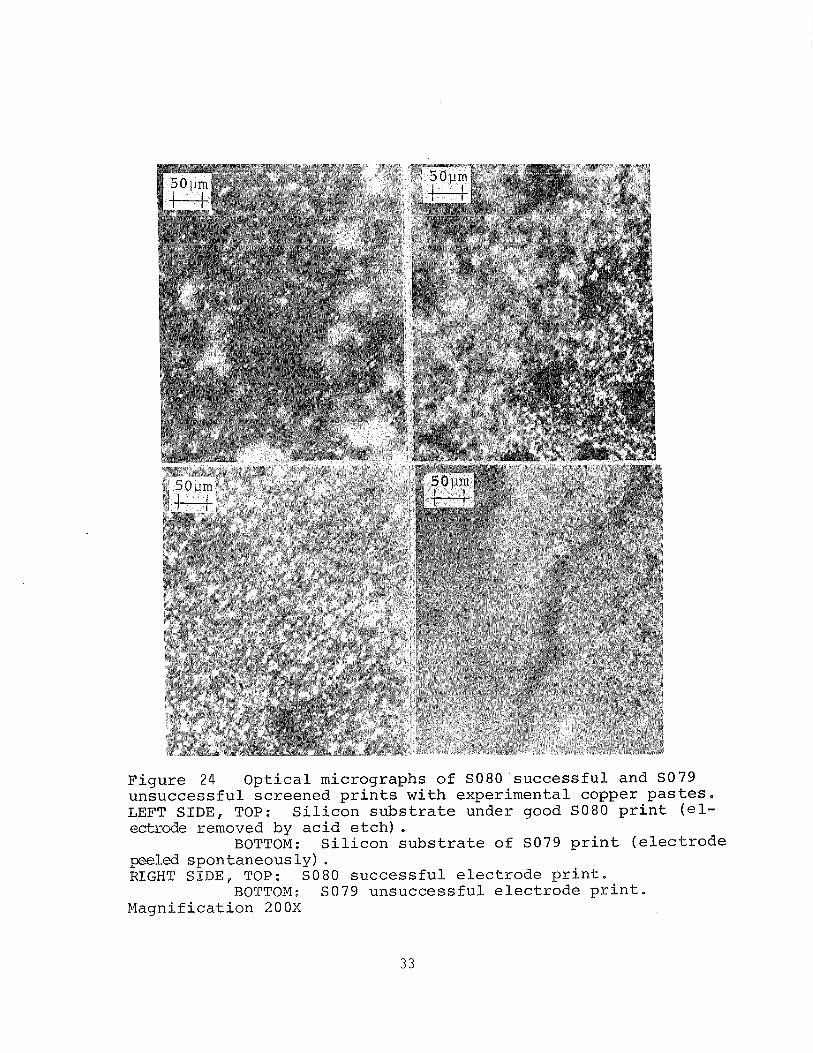
s t r a t e s (upper l e f t ) and SO80 p r i n t (upper r i g h t ) and unsuc-
c e s s f u l SO79 s u b s t r a t e (lower l e f t ) and SO79 p r i n t (lower
r i g h k ) , In t h e case of the s u b s t r a t e s the S08Q e lec t rode was
removed by e tching with concentrated n i t r i c a c i d , and t h e
SO79 electrode p r i n t peeled spontaneously. The d i f f e r e n c e
between SO80 and SO79 i s the use of germanium-silicon
e u t e c t i c a t 5wt.& i n t h e former and aluminum- s i l i c o n
eut-ect ic i n *.he l a t t e r ,
The major observable d i f f e rence i n t h e micrographs is t h e
l a r g e r g r a i n s i z e and coarser f a c e t i n g i n t h e case of t h e
successfu l SO80 pas te .
Figure 25 shows a composite of SEM micrographs depic t ing an
unsuccessful SO80 e lec t rod ing experiment. The s u b s t r a t e i s
shown on t h e l e f t s i d e and t h e e l e c t r o d e on t-he r i g h t , both
at- 1800x and a t 4500x. The f i r i n g of t h i s pas te a t 550°C by
t-he two s t e p process r e s u l t e d i n a small degree of s i n t e r i n g ,
making t h e micrograph resemble t h a t of a powder. By
c o n t r a s t , Figure 26 shows a success fu l p r i n t of the SO80
p a s t e taken on a Cambridge SEM a t roughly two magnif icat ions
1800 - 1900x, and 4500 - 4700x. The s t r i k i n g appearance of
t-he copper s i l i c o n e u t e c t i c needle s t r u c t u r e dominates t h e
p i c t u r e s of t h e s i l i c o n s u b s t r a t e . On t h e r i g h t t-he
e l ec t rode can be seen.
Figures 27 and 28 show black and white reproductions of t h e
co lo r readout of Xray d i spe r s ive s p e c t r a of successuful SO80
elect-rodes and the s i l i c o n s u b s t r a t e , r e spec t ive ly . The
spec t ra al low reading of t h e l i n e s of copper ( C u ) , Aluminum
( ~ l ) , l e a d ( P b ) s i l i c o n ( ~ i ) and s i l v e r ( ~ g ) i n F i g u r e 27 and
s i l i c o n , alutninum s i l v e r , c o p p e r and t h e t i n ( ~ n ) i n F i g u r e
28 . T h e f i g u r e s a r e shown o n l y a s i l l u s t r a t i v e o f t h e
method, a s no c l u e s f o r the d i f f e r e n c e s i n p e r f o r m a n c e c o u l d
be o b t a i n e d f rom t h e s p e c t r a .
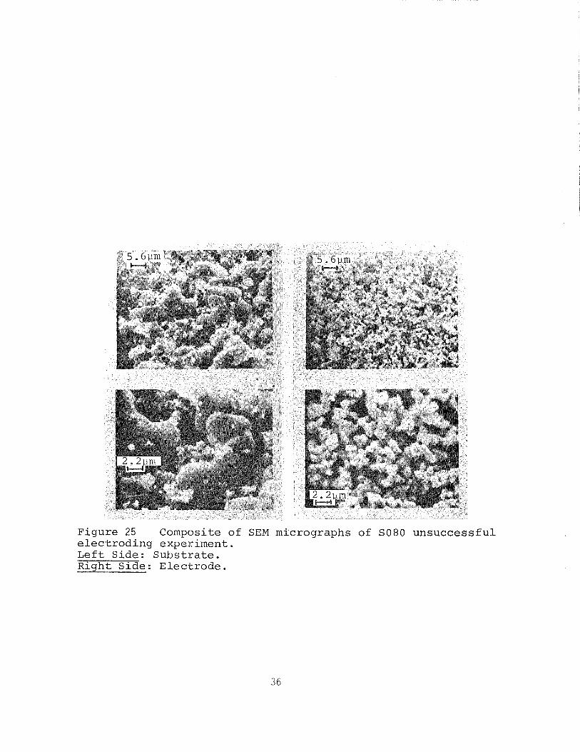
Figure 25 Composite of SEM micrographs of SO80 unsuccess fu l e l e c t r o d i n g experiment. L e f t Side: Subs t r a t e . Right S ide : E lec t rode .
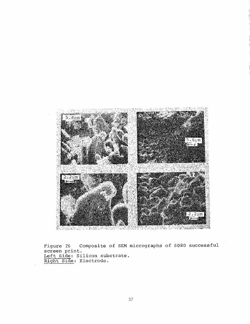
Figure 26 Composite of SEM micrographs of S O 8 0 s u c c e s s f u l s c r e e n p r i n t . L e f t Side: S i l i c o n s u b s t r a t e . P
Right Side: E lec t rode .
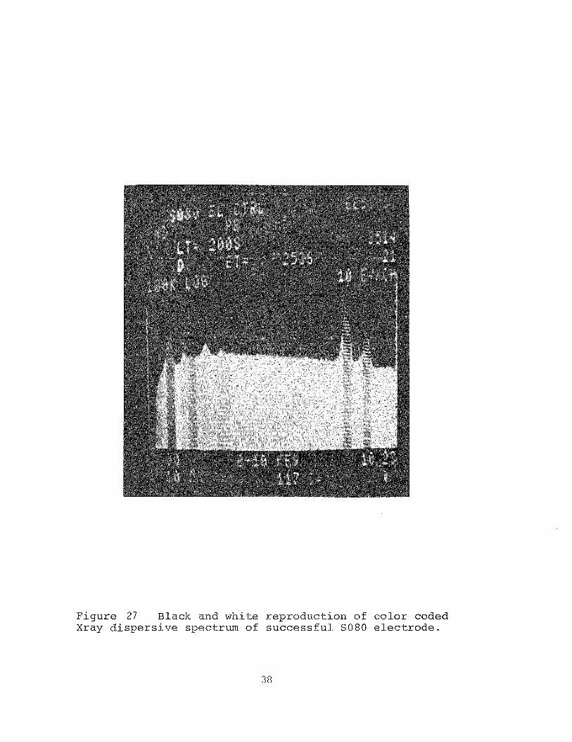
Figure 27 Black and white reproduct ion of co lo r coded Xray d i s p e r s i v e spectrum of success fu l SO80 e lec t rode .
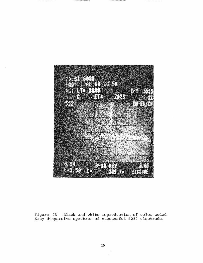
Figure 28 B l a c k and whi te r ep roduc t ion of c o l o r coded Xray d i s p e r s i v e spectrum of s u c c e s s f u l SO80 e l e c t r o d e .
5.0 FLUOROCARBON CONTAINING COPPER PASTES
5.1 Paste, Contact Experiments and Analysis
During the present contract, paste formulation was transfer-
red to a new subcontract facility. The purpose of this
change was to allow more intimate control of material and
process by direct contract personnel.
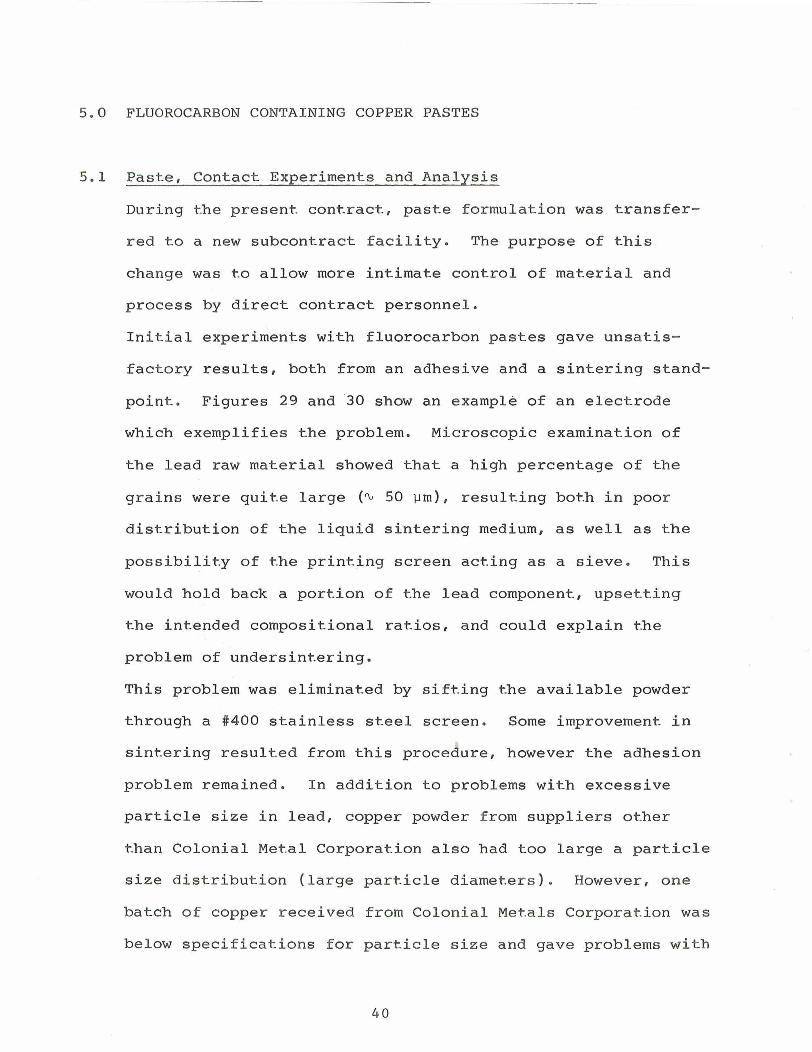
Initial experiments with fluorocarbon pastes gave unsatis-
factory results, both from an adhesive and a sintering stand-
point. Figures 29 and 30 show an example of an electrode
which exemplifies the problem. Microscopic examination of
the lead raw material showed that a high percentage of the
grains were quite large (Q 50 urn), resulting both in poor
distribution of the liquid sintering medium, as well as the
possibility of the printing screen acting as a sieve. This
would hold back a portion of the lead component, upsetting
the intended compositional ratios, and could explain the
problem of undersintering.
This problem was eliminated by sifting the available powder
through a #400 stainless steel screen. Some improvement in
sintering resulted from this procedure, however the adhesion
problem remained. In addition to problems with excessive
particle size in lead, copper powder from suppliers other
than Colonial Metal Corporation also had too large a particle
size distribution (large particle diameters). However, one
batch of copper received from Colonial Metals Corporation was
below specifications for particle size and gave problems with
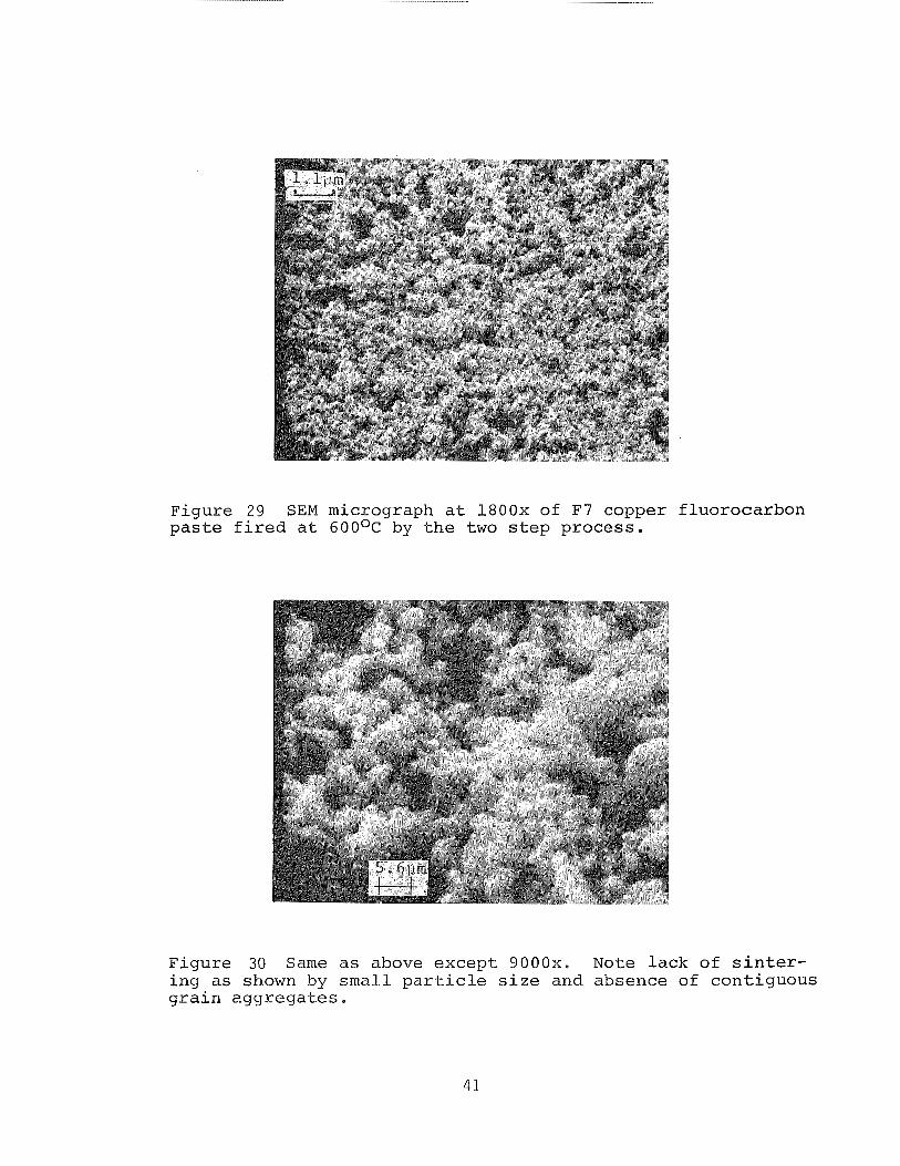
Figure 2 9 SEM micrograph a t 1800x of F7 copper f luorocarbon p a s t e f i r e d a t 6 0 0 ~ ~ by t h e two s t e p process .
F igure 30 Same a s above excep t 9000x. Note lack of s i n t e r - i n g a s shown by smal l p a r t i c l e s i z e and absence of con t iguous g r a i n egg rega t e s .
a) the amount of powder that could be accommodated by a given
quantity of vehicle (metal content) and b) the apparent
"fluffiness" of the metal powder. Both a) and b) are attri-
butable to smaller than usual particle diameters. A total of
99 different paste formulations were manufactured by the
previous subcontractor including many attempts to reproduce
S071, SO79 and SO80 which represented the best solar cell
6 electrodes made to date (previous contract #955164) . It was
deemed appropriate to start a new numbering system for pastes
manufactured by the new subcontractor, beginning with F1
(which would have been SlOO under the old scheme). The first
fluorocarbon ink in this series was F4 utilizing 0.7 wt%
fluorocarbon powder with the results described above. Pastes
were produced with various copper powders including copper
flake (see Section 4.1), without a marked improvement.
Fluorocarbon content was varied from 0.7 wt% (F4) to 2.1 wt%
(F11) with the medium range (1.0 to 1.2 wt%) yielding the
best results.
An extensive analysis was undertaken by Dr. Joseph Parker, of
the possible chemical reactions of the paste constituents
throughout the thermal history of the screened electrodes. A
set of simple equations was written and the thermochemical
analysis was done, based upon heats of reaction from
published or derived heats of formation, for the various
compounds. The numerical value and algebraic signs of the
heats of formation indicate the likelihood that certain
reactions should be emphasized or reduced in extent. This
suggests a change in composition. Subsequently it was
desirable to verify these clues by direct experimentation and
further physical analysis with differential thermal analysis
(DTA) and thermal gravimetric analysis (TGA) (see Section
7.0).
The above analysis showed that it would be desirable to
provide an additional liquid medium, whose function was to
promote contact between the copper powder grains and the
freshly exposed silicon surface, during the scavenging
activity of the fluorine from the fluorocarbon source.
Earlier work with silver fluoride had shown that the fluorine
scavenging activity takes place very rapidly ( % 1 sec), while
the silver fluoride salt is in a liquid form. The reaction
products, solid silver metal and gaseous silicon tetrafluo-
ride, as well as water, drive the reversible reaction on one
direction through the mass action law, and the contact
between silver and silicon is a consequence of the reaction
site. Contact between the copper grains and the silver
fluoride is promoted by the liquid lead (liquid phase
sintering medium), during the longer term of the sintering
step. In the case of the fluorocarbon decomposition the
reaction proceeds without the presence of sufficient liquid
phase, making the contact between copper and freshly exposed
silicon less probable. This is because the amount of fluoro-
carbon has to be kept low due to other potential spoiler
reactions and due to the low density of fluorocarbon making
it a nonideal transport medium. An additional liquid medium,
lead acetate, melting point 280°C, was therefore chosen t o
transport copper g r a i n s t o freshly exposed s i l icon s i t e s .
Liquid sint-ering of the copper matrix is s t i l l thought t o be
a solution growth phenomenon accomplished by the l iquid metal
lead.
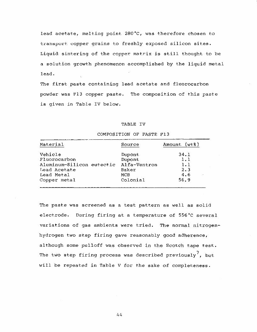
The f i r s t paste containing lead acetate and fluorocarbon
powder was F13 copper paste. The composition of t h i s paste
i s given i n Table I V below.
TABLE I V
COMPOSITION OF PASTE F13
Material Source Amount ( w t % )
Vehicle Dupont 34.1 Fluorocarbon Dupont 1.1 Aluminum-Silicon eutect ic Alfa-Ventron 1.1 Lead Acetate Baker 2 . 3 Lead Metal MCB 4.6 Copper metal Colonial 56.9
The paste was screened as a t e s t pattern as well as sol id
electrode. During f i r ing a t a temperature of 556°C several
variations of gas ambients were t r i e d . The normal nitrogen-
hydrogen two s tep f i r i n g gave reasonably good adherence,
although some pulloff was observed i n the Scotch tape tes t .
7 The two s tep f i r i n g process was described previously , but
w i l l be repeated i n Table V for the sake of completeness.
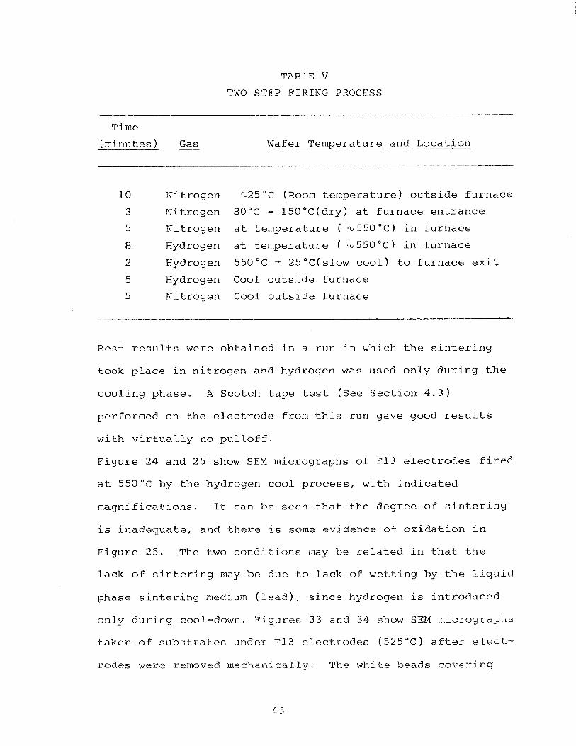
TABLE V
TWO STEP FIRING PROCESS
Time
( m i n u t e s ) Gas Wafer T e m p e r a t u r e a n d L o c a t i o n
1 0 N i t r o g e n %25"C ( ~ o o m t e m p e r a t u r e ) o u t s i d e f u r n a c e
3 N i t r o g e n 80°C - 1 5 0 ° C ( d r y ) a t f u r n a c e e n t r a n c e
5 N i t r o g e n a t t e m p e r a t u r e ( % 550 " c ) i n f u r n a c e
8 Hydrogen a t t e m p e r a t u r e ( ~ 5 5 0 " ~ ) i n f u r n a c e
2 Hydrogen 550°C + 2 5 " C ( s l o w c o o l ) t o f u r n a c e e x i t
5 Hydrogen Coo l o u t s i d e f u r n a c e
5 N i t r o g e n C o o l o u t s i d e f u r n a c e
R e s t r e s u l t s were o b t a i n e d i n a r u n i n which t h e s i n t e r i n g
t o o k place i n n i t r o g e n and h y d r o g e n w a s u s e d o n l y d u r i n g the
c o o l i n g phase. A S c o t c h tape t e s t (see S e c t i o n 4 . 3 )
p e r f o r m e d on t h e e l e c t r o d e f r o m t h i s r u n g a v e good r e s u l t s
w i t h v i r t u a l l y n o p u l l o f f .
F i g u r e 24 a n d 25 show SEM m i c r o g r a p h s o f F13 e l e c t r o d e s f i r e d
a t 550°C by t h e h y d r o g e n cool p r o c e s s , w i t h i n d i c a t e d
m a g n i f i c a t i o n s . I t c a n b e s e e n t h a t t h e d e g r e e o f s i n t e r i n g
i s i n a d e q u a t e , a n d t h e r e i s some e v i d e n c e o f o x i d a t i o n i n
F i g u r e 25. The two c o n d i t i o n s may be r e l a t e d i n t h a t t he
l a c k o f s i n t e r i n g may be d u e t o l a c k o f w e t t i n g by t h e l i q u i d
p h a s e s i n t e r i n g medium ( l e a d ) , s i n c e h y d r o g e n i s i n t r o d u c e d
o n l y d u r i n g cool-down. F i g u r e s 3 3 and 34 show SEM m i c r o g r a p ~ l ~
t a k e n o f s u b s t r a t e s u n d e r F13 e l e c t r o d e s ( 5 2 5 ° C ) a f t e r e l ec t -
r o d e s were removed m e c h a n i c a l l y . The w h i t e h e a d s c o v e r j n g
Figure 31 1800x F igure 32 9000x SEM micrographs of F13, copper f luorocarbon e l e c t r o d e .
F igure 33 l800x F igure 34 9000x SEM micrographs of s u b s t r a t e s under above e l e c t r o d e s ,
t h e su r face appear t o be d i e l e c t r i c i n na ture judging from
the presumed charging e f f e c t s of F i g u r e 34. Therefore we
be l i eve t h e ma te r i a l t o have r e s u l t e d from t h e lead a c e t a t e
and expect i t t o be lead oxide.
5 . 2 Sol-ar Ce l l Experiments
Screening experiment with F13, 16, 1 7 and F20 p a s t e was made
on 2 X 2 cin phosphorus d i f fused , l a s e r scr ibed and broken
s o l a r c e l l ma te r i a l . The back contac t only was provided w i t h
a screened e lec t rode of t h e above p a s t e s . The specimens were
f i r e d by t h e normal two s t e p procedure a t 5 7 5 " ~ and 6 2 5 " ~ .
The r e s u l t s were va r i ab le with most specimens f a i l i n g t h e
Scotch tape t e s t . One device (no t tape t e s t e d ) was t r a n s -
mitted t o t h e J e t Propulsion Lab f o r app l i ca t ion of f r o n t
contac ts ( ~ i - P d - ~ g ) and measurement.
The I V curve is shown i n Figure 35. The curve i s cha rac te r -
i s t i c of poor s e r i e s and shunt r e s i s t a n c e . An at tempt t o
e t ch the c e l l edge t o inc rease shunt r e s i s t a n c e r e s u l t e d i n
some improvement i n open c i r c u i t vol tage but s imultaneously
increased t h e s e r i e s r e s i s t a n c e , presumably a s the c e l l mask
( t a p e ) was removed. While t h e device e l ec t rode ( ~ 1 6 screened
p a s t e ) i s f a r from optimized, it i s an ind ica t ion t h a t t h e
fluorocarbon containing p a s t e i s v iab le f o r s o l a r c e l l
e l e c t r o d e s . The uncoated s o l a r c e l l had e f f i c i e n c y of 7 .0%
i n i t i a l l y (corresponding t o 9 . 6 % AM1 with AR c o a t i n g ) .
amps
e EB
- L O
*Ob
CELL ID: F-Lb @ C E L L ID: F-Lb Process : 525 F-Lb AEE Process : 525 F-LA AEE
C a f t e r edge e t c h 3 { a f t e r edge e t ch3
E f f e = 8 - 9 2 E f f * 7.0 5 C e l l Area= 4 sq. cm. C e l l Area= 4 sq. cm. F i l l F a c t o r = 8.59 F i l l F a c t o r = 0.b4I.1
F i g u r e 35
I V c u r v e s o f s o l a r c e l l s w i t h G-lb coppe r and f l u o r o c a r b o n back c o n t a c t -
1 * 0 v o l t s 4 8
6.0 FRONT CONTACT CONSIDERATIONS
The theory of ohmic contacts was reviewed particularly with
regard to the metal semiconductor contact parameters and
tunneling equations. Some errors were discovered in the
literature (see Appendix Ref. #6) which were corrected on the
basis of the original references (for example, Ref. #18,
ibid). A paper was prepared including the findings. This
was presented at the 4th E.C. Photovoltaic Solar Energy Con-
ference, May 1982 in Stresa, Italy by courtesy of Dr. William
Callaghan, since the author was unable to attend for health
reasons. A copy of the paper is attached in the appendix.
6.1 Theory
The front contact of modern solar cells is applied to nearly
degenera-te n type semiconductor surfaces with impurity
concentrations from 10 l9 atoms/cmm3 to 10 21 atom~/cm-~
with phosphorous being the donor conventionally in use. Due
to the high surface concentration and resulting high
conductivity in accordance with
(1) =Nql-l
-1 where o = conductivity (R cm)
-3 N = carrier concentration, cm
q = electronic charge, coulombs
2 mobility, cm /V - sec
it is relatively simple to provide a good ohmic contact to
the front surface of solar cells. This results from the fact
that the electron tunneling probability is a function of the
carrier concentration on both sides of the interface. When a
metal coats the surface of a semiconductor, the depletion
width within the semiconductor shrinks as a function of
carrier concentration, thereby enhancing the tunneling
probability. An enhanced tunneling probability provides for
ready carrier flow through the barrier constituted by the
contact potential between contact metal and semiconductor
surface.
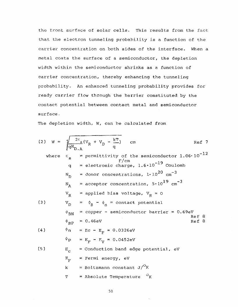
The depletion width, W, can be calculated from
Ref 7
-12 where cS = permittivity of the semiconductor 1.06.10 ~ / c m -19
q = electronic charge, 1.6010 Coulomb
N~ = donor concentrations, 1. lo2' cmm3
19 -3 N~ = acceptor concentration, 5.10 crn
v~ = applied bias voltage, VR = 0
v~ = $B - $n = contact potential
+BN = copper - semiconductor barrier = 0.69eV Ref 8
~ B P = 0.46eV Ref 8
Ec = Conduction band edge potential, eV
E~ = Fermi energy, eV
k = Boltzmann constant J/OK
T = Absolute Temperature V~
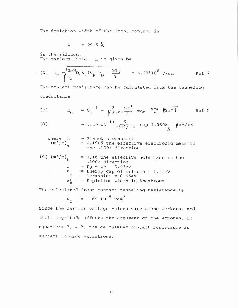
The depletion width of the front contact is
in the silicon. The maximum field m is given by
Ref 7
The contact resistance can be calculated from the tunneling
conductance
- -1 W Rc - Go = p F 4 ~ 47n.d I/- (h12 exp
where h (m*/mIe
-1 1 2 = 3.16.10 , l y exp 1.035W /- m /m4 R
= Planck's constant = 0.1905-the effective electronic mass in the <loo> direction
(9) (m*/mIh = 0.16 the effective hole mass in the <loo> direction
4 = Eg - 4B = 0.42eV E 9
= Energy gap of silicon = l.lleV Germanium = 0.65eV
Wg = Depletion width in Angstroms
The calculated front contact tunneling resistance is
Since the barrier voltage values vary among workers, and
their magnitude affects the argument of the exponent in
equations 7, & 8, the calculated contact resistance is
Ref 9
subject to wide variations.
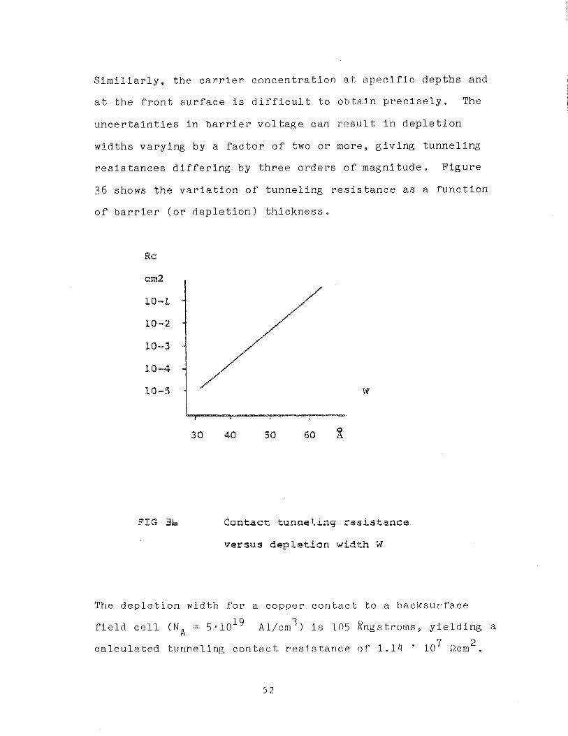
S i m i l i a r l y , t h e c a r r i e r c o n c e n t r a t i o n a t s p e c i f i c d e p t h s and
a t t h e f r o n t s u r f a c e i s d i f f i c u l t t o o b t a i n p r e c i s e l y . The
u n c e r t a i n t i e s i n b a r r i e r v o l t a g e can r e s u l t i n d e p l e t i o n
w i d t h s v a r y i n g by a f a c t o r o f two o r more, g i v i n g t u n n e l i n g
r e s i s t a n c e s d i f f e r i n g by t h r e e o r d e r s o f m a g n i t u d e . F i g u r e
36 shows t h e v a r i a t i o n o f t u n n e l i n g r e s i s t a n c e as a f u n c t i o n
o f b a r r i e r ( o r d e p l e t i o n ) t h i c k n e s s .
F I G 3b C o n t a c t tunnelsing rtsistance
versus dep le t ion w i d t h W
The d e p l e t i o n w id th f o r a c o p p e r c o n t a c t t o a b a c k s u r f a c e
3 f i e l d c e l l (NA = Al/crn ) i s 105 #ngs t roms , y i e l d i n g a
2 c a l c u l a t e d t u n n e l i n g c o n t a c t r e s i s t a n c e o f 1 . 1 4 * l o 7 ncm .
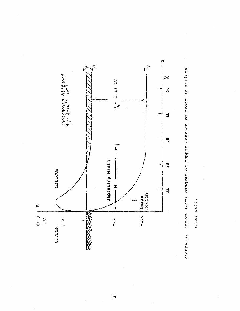
The e n e r g y band r e l a t i o n s h i p s f o r a c o p p e r c o n t a c t on a
s i l i c o n f r o n t s u r f a c e doped w i t h I a 1 0 2 0 phosphorus atoms/cm 3
a r e shown i n F i g u r e 37 u s i n g t h e v a l u e s c a l c u l a t e d above .
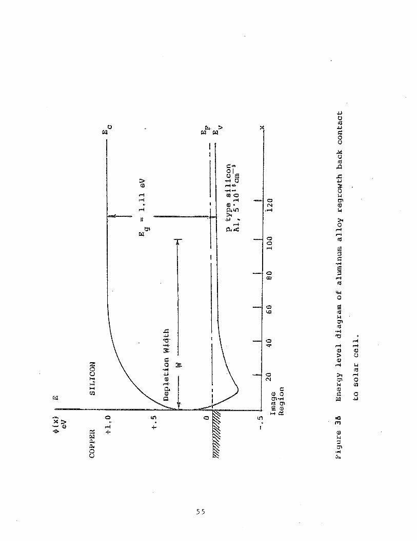
Fo r t h e s a k e o f c o m p l e t e n e s s an e n e r g y band d i ag ram i s
i n c l u d e d i n F i g u r e 38 d e p i c t i n g t h e back c o n t a c t r e l a t i o n -
s h i p s f o r a BSF c e l l , o r a coppe r c o n t a c t c o n t a i n i n g e u t e c t i c
aluminum-germanium (S080) a h e t e r o e p i t a x i a l s i t u a t i o n
e x i s t s , l e a d i n g t o a s m a l l e r band g a p on t h e s e m i c o n d u c t o r
s i d e o f t h e c o n t a c t (EG (germanium) = 0.65eV).
Fo r t h e c a s e o f a germanium-aluminum c o n t a c t a l l o y on t h e
c e l l b a c k s u r f a c e , t h e r e d e p o s i t i o n o f aluminum doped
germanium on t h e s i l i c o n l e a d s t o a n a r r o w e r d e p l e t i o n w i d t h 0
o f 23.2 Angstroms due t o a h i g h e r c a r r i e r c o n c e n t r a t i o n (NA =
3 1 . 3 ' l o 2 ' Al.cm ) and s m a l l e r b a r r i e r h e i g h t o f 0.42 eV.
The e f f e c t i v e mass o f t h e h o l e i s a l s o c o n s i d e r a b l y smaller m *
i n germanium ( ifi = 0 . 0 4 2 ) . T h i s l e a d s t o a t u n n e l i n g r e s i s t -
a n c e o f 7 .5 ohm-cm.
When t h e s e m i c o n d u c t o r s u r f a c e h a s a h i g h e r r e s i s t i v i t y , i t
may be n e c e s s a r y t o make s p e c i a l p r o v i s i o n s i n a p p l y i n g t h e
ohmic c o n t a c t by u t i l i z i n g a t e c h n i q u e t o dope t h e s u r f a c e o f
t h e s e m i c o n d u c t o r u n d e r t h e e l e c t r o d e metal . When f i r i n g
? t e m p e r a t u r e s a re s u f f i c i e n t l y h i g h ( - 800°C) t h i s may b e d o n e
by i n c l u d i n g a n e l e m e n t a l donor i m p u r i t y i n t h e metal and
a l l o w i n g i t t o d i f f u s e i n t o t h e s e m i c o n d u c t o r d u r i n g t h e
f i r i n g s t e p , by s o l i d s t a t e d i f f u s i o n , S i n c e o n l y t h e
s u r f a c e n e e d s t o be doped , t h e d o n o r a tom must become a s u b -
s t i t u t i o n a l i m p u r i t y i n t h e s i l i c o n l a t t i c e w i t h i n a few
lattice spaces oE the surface, W brief firing period will
~ r s a a l i y s t .~ f r i ce. -
at very low temperature ( 6 0 0 " ~ ) it may be difficult to
obtain a sufficient surface concentration of dopant atoms by
diffusion and therefore a different technique is employed. A
eutectic alloy of dopant and semiconductor material is made a
part o f the electrode paste with the object of getting some
of the cutectic to bridge semiconductor and metal. During
the firing step the eutectic melts, dissolving more silicon.
As the temperature is lowered again the dissolved silicon
precipitates on the surface, re-tai-ning donor solid solubility
concentrati-ons, and thereby facilitating ohmic contact.
Since the solid solubility of some elements in silicon is
small, the use of this method is beneficial only when the
front surface donor concentration is less than the donor
solid solubility.
6.2 Experiments -
Two pastes were prepared for the front contact experiment.
S O 7 1 is an undoped copper paste, which should provide the
desired contact on phosphorus diffused solar cells, by virtue
of the above arguments. A paste was also prepared to address
the second possibility, providing an epitaxial crystalline
layer, doped with antimony. This paste was fabricated by
producing an eutectic alloy of antimony-germanium, reducing
the resulting ingot to powder, and adding the material to the
paste (5 wt.%).
A number o f c o n t a c t r e s i s t a n c e measurements were made
u t i l i z i n g c o p p e r p a s t e F31 ( c o m p o s i t i o n copper 64.82 w t , %
l e a d 6.48 w t . % s i l v e r f l u o r i d e 0 , 7 0 w t , % w i t h o u t e u t e c t i c
a d d i t i o n ) and F32 (s imilar t o F31 p l u s 3 .1 w t . % aluminum-
s i l i c o n e u t e c t i c ) . P r i n t s were made w i t h t h e l i n e a r c o n t a c t
r e s i s t a n c e a r r a y p r e v i o u s l y r e p o r t e d , f i r e d i n ca rbon
monoxide a t 550°C, 600°C. 650°C. While t h e r e was some d a t a
s c a t t e r , F32 w i t h e u t e c t i c a d d i t i o n s g a v e t h e l o w e s t c o n t a c t
r e s i s t a n c e a t t h e h i g h e r t e m p e r a t u r e s ( 5 ohm cm2 a t
650°C).
A measurement on a 7001 s i l i c o n n i t r i d e c o a t e d phosphorus
2 d i f f u s e d wafe r g a v e a c o n t a c t r e s i s t a n c e o f 1*10-* ohm crn ,
u t i l i z i n g F25, a copper p a s t e w i t h 5 w t . % AgF f o r S i j N 4
l a y e r p e n e t r a t i o n . Subsequent a n a l y s i s showed t h a t t h e u s e
of t h e l i n e a r a r r a y w i t h o u t l i m i t i n g t h e l a t e r a l c u r r e n t f l u x
e x c u r s i o n s can l e a d t o measurement e r r o r s . T h i s can be
avo ided by c u t t i n g a b a r o f w i d t h e q u a l t o t h e o u t e r c u r r e n t
e l e c t r o d e s .
A d d i t i o n a l measurements c a r r i e d o u t by D r . Wi l l iam T a y l o r ,
Pho towa t t , I n t l . , s u g g e s t e d t h a t t h e PN j u n c t i o n s o f t h e s e
wafers were p e r f o r a t e d , o r s h u n t e d by t h e F25 e l e c t r o d i n g
p r o c e s s . New s c r e e n s were d e s i g n e d and f a b r i c a t e d i n o r d e r
t o a l l o w u t i l i z a t i o n o f c o n v e n i e n t and economical 2cm x 2cm
s o l a r c e l l b l a n k s . A d e s i g n was made f o r a u n i v e r s a l t e s t
p a t t e r n and s o l a r c e l l f r o n t and back e l e c t r o d e s . These
cou ld be used b o t h f o r b a s i c i n k p a r a m e t e r measurements and
s o l a r c e l l c o n t a c t e x p e r i m e n t a t i o n , The t e s t p a t t e r n a l l o w s
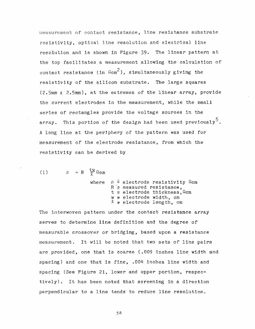
rneaslrrernent o f c o n t a c t r e s i s t a n c e , l i n e r e s i s t a n c e s u b s t r a t e
r e s i s t i v i t y , o p t i c a l l i n e r e s o l u t i o n and e l e c t r i c a l l i n e
r e s o l u t i o n and i s shown i n F i g u r e 39. The l i n e a r p a t t e r n a t
t h e t o p f a c i l i t a t e s a measurement a l l o w i n g t h e c a l c u l a t i o n o f
;ri c o n t a c t r e s i s t a n c e ( i n Qcm ), s i m u l t a n e o u s l y g i v i n g t h e
r e s i s t i v i t y o f t h e s i l i c o n s u b s t r a t e . The l a r g e s q u a r e s
(2.5mm x 2.5mm), a t t h e ex t r emes o f t h e l i n e a r a r r a y , p r o v i d e
t h e c u r r e n t e l e c t r o d e s i n t h e measurement, w h i l e t h e s m a l l
s e r i e s o f r e c t a n g l e s p r o v i d e t h e v o l t a g e s o u r c e s i n t h e
5 a r r a y . T h i s p o r t i o n o f t h e d e s i g n had been used p r e v i o u s l y . A l o n g l i n e a t t h e p e r i p h e r y o f t h e p a t t e r n was used f o r
measurement o f t h e e l e c t r o d e r e s i s t a n c e , from which t h e
r e s i s t i v i t y c a n b e d e r i v e d by
tw Qcm
where P = e l e c t r o d e r e s i s t i v i t y Qcm R r measured r e s i s t a n c e , t e l e c t r o d e t h i c k n e s s , n c m w E e l e c t r o d e w i d t h , cm 9, s e l e c t r o d e l e n g t h , cm
The in t e rwoven p a t t e r n under t h e c o n t a c t r e s i s t a n c e a r r a y
s e r v e s t o d e t e r m i n e l i n e d e f i n i t i o n and t h e d e g r e e o f
measurab le c r o s s o v e r o r b r i d g i n g , based upon a r e s i s t a n c e
measurement. I t w i l l be n o t e d t h a t two s e t s o f l i n e p a i r s
a r e p r o v i d e d , one t h a t i s c o a r s e ( .009 i n c h e s l i n e width a n d
s p a c i n g ) and one t h a t i s f i n e , .004 i n c h e s l i n e w i d t h and
s p a c i n g (See F i g u r e 21, lower and upper p o r t i o n , r e s p e c -
t i v e l y ) . I t h a s been n o t e d t h a t s c r e e n i n g i n a d i r e c t i o n
p e r p e n d i c u l a r t o a l i n e t e n d s t o r educe l i n e r e s o l u t i o n .
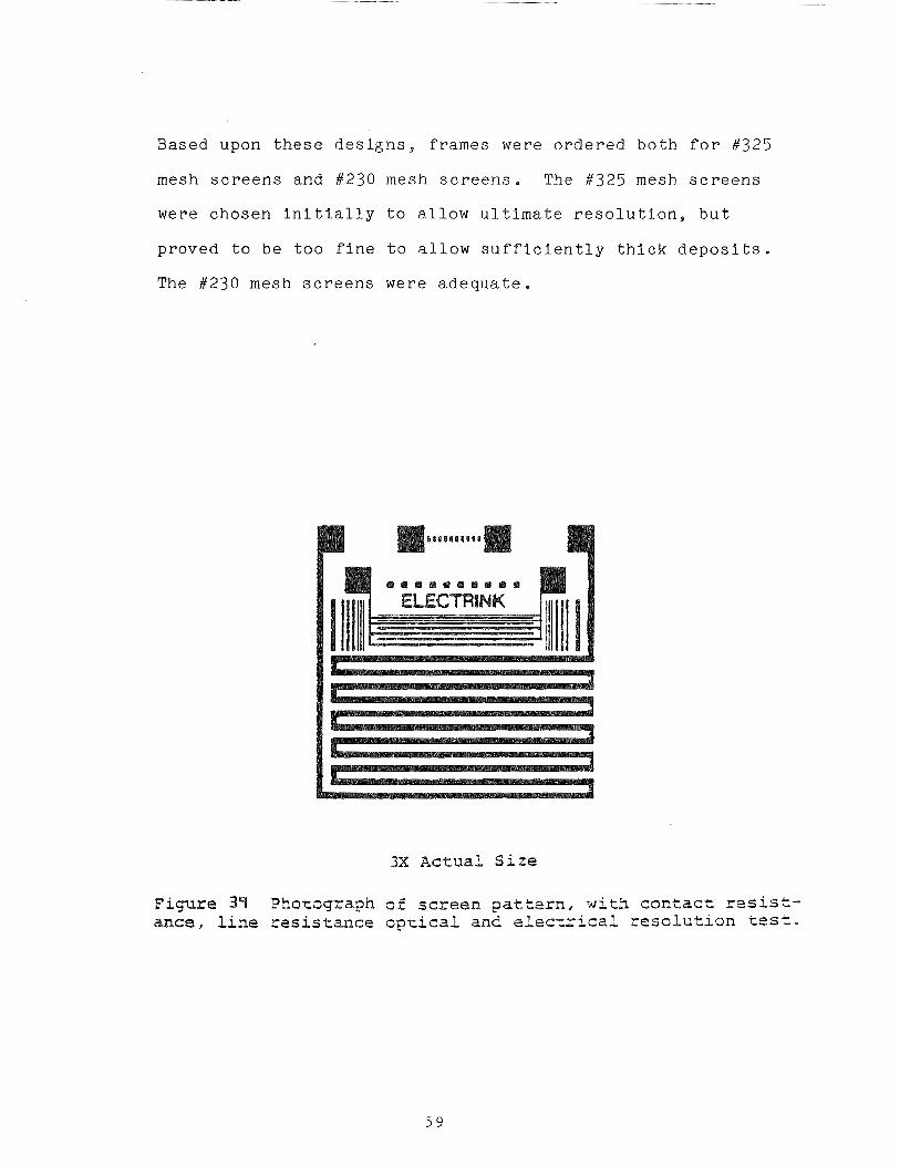
Based upon t h e s e d e s i g n s , f r a m e s were o r d e r e d b o t h f o r # 3 2 5
mesh s c r e e n s and #230 mesh s c r e e n s . The #325 mesh s c r e e n s
were c h o s e n i n i t i a l l y t o a l l o w u l t i m a t e r e s o l u t i o n , b u t
p r o v e d t o be t o o f i n e t o a l l o w s u f f i c i e n t l y t h i c k d e p o s i t s .
The # 2 3 0 mesh s c r e e n s were a d e q u a t e .
3X Actual Size
F i y r e 39 Photsgraph 02 s c r e e n p a t t e r n , with c o n t a c t r a s i s t - ance, l i n e rssistmce optical and electriczl r e s o l c t i o n tos=-
7.0 THEORETICAL CONSIDERATIONS OF REACTIONS
The firing process involves the heating in special
atmospheres, and at elevated temperatures, of a multi-
component metal powder ink. These conditions favor the
occurrence of numerous chemical reactions.
Such reactions are thought to be the cause of observed poor
reproducibility of some performance characteristics of the
ink despite care taken to control known parameters. One
means for gaining an insight to the possible reactions is the
analysis of reasonable combinations or disintegrations of
materials present and using principles of chemical thermo-
dynamics and kinetics, to evaluate (even if only qualita-
tively) the probability that such reactions actually take
place.
The heat of a reaction is a readily obtained measure of the
tendency of a reaction to proceed. Reactions which produce a
great deal of heat are much more likely to occur than those
which require the absorption of much heat. The development
of the enthalpy change of reaction heat arises from the
definition of the enthalpy change of a process viz.
AH- AE+ A(Pv),
and the first law of thermodynamics,
AE=Q-W= AH-~(pv).
In these equations p is the pressure, V is the volume, and AE
is the total energy change for a system change in which an
amount of heat, Q , is added to the system and an amount of
work W , i s removed from t h e system. In t he case of t he
react ions of i n t e r e s t the process i s one which takes p lace a t
constant pressure and involves only volume change work. This
leads t o :
A 'r = Q -W + A ( ~ v ) = Qp P
Which i s the enthalpy change o r "heat of reac t ion" fo r a
constant pressure process.
L e t us now consider t h e constant pressure combustion of
methane where
CH4 + 202 $ C02 + 2H20
The enthalpy change f o r t h i s reac t ion i s :
- h e r e -the subscripted values a r e the enthalp ies of the
indica ted molecules. This i s simply t he d i f fe rence between
the i n i t i a l and f i n a l system enthalp ies . The above r e l a t i o n
may a l s o be wr i t t en a s t he enthalpy equation,
Conservation of matter concepts allow u s t o use molecular
hea t s of formation f o r t he subscripted enthalp ies because
elemental enthalp ies cancel (and a r e given a value of z e ro
when they appear i n a r eac t i on ) when enthalpy changes a r e
computed. Tables of hea t s of formation a r e r ead i l y found
( ~ e f s . 10, 11 & 1 2 ) and t h i s f a c t makes the rough ca l cu l a t i on
of hea t s of reac t ion a f a i r l y simple matter i n most cases .
The hea t s of formation f o r t h e gaseous molecules of t h i s
example are :
A H e H = -17.4, AH, = 0.0, AH,, = -94.1, AH^ 0 - - - 5 7 . 8
4 2 2 2
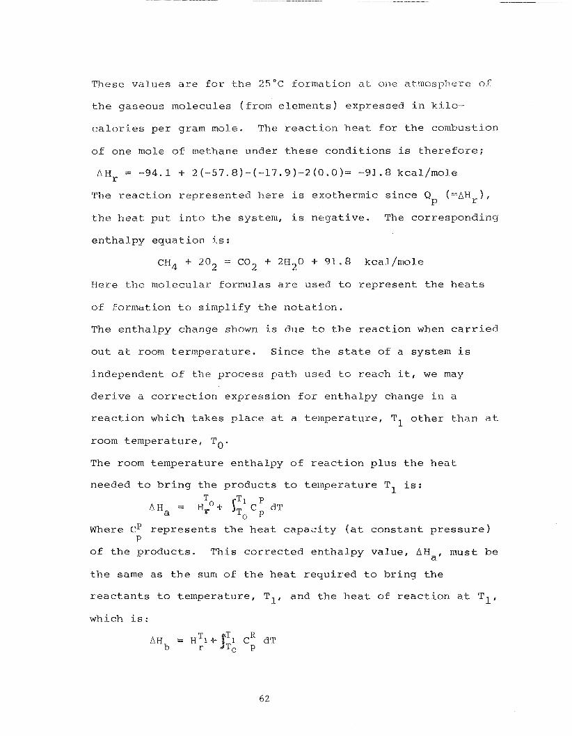
These values are f o r the 2 5 ° C formation ak one atrnosplzere of
the gaseous molecules (from elements) expressed in kilo-
calories per gram mole. The reaction heat for the combustion
of one mole of methane under these conditions is therefore;
The reaction represented here is exothermic since Q ('AH,). P
the heat put into the system, is negative. The corresponding
enthalpy equation is:
CH4 + 202 = C 0 2 + 2H20 + 91.8 kcal/mole
Here the molecular formulas are used to represent the heats
of formation to simplify the notation.
The enthalpy change shown is due to the reaction when carried
out at room termperature. Since the state of a system is
independent of the process path used to reach it, we may
derive a correction expression for enthalpy change in a
reaction which takes place at a temperature, TI other than at
room temperature, To.
The room temperature enthalpy of reaction plus the heat
needed to bring the products to temperature T1 is: T T l P
Ha = H y O t I C dT p
Where CP represents the heat capacity (at constant pressure) P
of the products. This corrected enthalpy value, AHa, must be
the same as the sum of the heat required to bring the
reactants to temperature, TI, and the heat of reaction at TI,
which is:
P Where C represents t h e h e a t capaci ty of t h e r e a c t a n t s . When
P
t h e s e a r e equated ( Ha= H b ) t h e des i red value f o r t h e
enthalpy of r eac t ion a t T I is obtained by rearrangement and
combination of terms. Thus,
The cor rec t ion term i n t h e above equation involves hea t
c a p a c i t i e s a t cons tant p ressu re which a r e , i n genera l ,
funct ions of temperature.
I t was implied e a r l i e r t h a t t h e l a r g e r t h e exothermic h e a t ,
t h e g r e a t e r the tendency f o r t h e r eac t ion , a s w r i t t e n , t o
proceed from l e f t t o r i g h t . We may i n f e r from t h e d i scuss ion
of t h e hea t of r eac t ion t h a t s t rong ly endothermic reac t ions
tend t o proceed f r o m r i g h t t o l e f t .
Two f a c t o r s which may modify o r even overr ide t h e above
cons idera t ions a re : 1. Reaction a c t i v a t i o n energy and 2 . Mass
a c t i o n e f f e c t s . Values f o r t h e former a r e obtained from
inves t iga t ions of t h e k i n e t i c s of the r eac t ion . These w i l l
not be d e t a i l e d here . The l a t t e r a r e based on t h e genera l
observat ion t h a t r e a c t i o n r a t e s increase with an i n c r e a s e i n
t h e amount o r concent ra t ion of r eac tan t s . When a r e a c t i o n
produces a gas and a condensed molecule s o t h a t t h e gas t e n d s
t o sepa ra te from t h e o t h e r products , t h e reverse o r r i g h t - t o -
l e f t r eac t ion i s i n h i b i t e d by t h e l o s s of t h e gas . This
r ep resen t s a ne t inc rease i n t h e l e f t - t o - r i g h t r eac t ion .
Because a c t i v a t i o n energy i s o f t e n an i n f l u e n t i a l f a c t o r i n
t h e observed vigor of a p a r t i c u l a r r eac t ion scheme, a v a i l a b l e
i n d i c a t i o n s of a c t u a l r eac t ion o r non-reaction t a k e
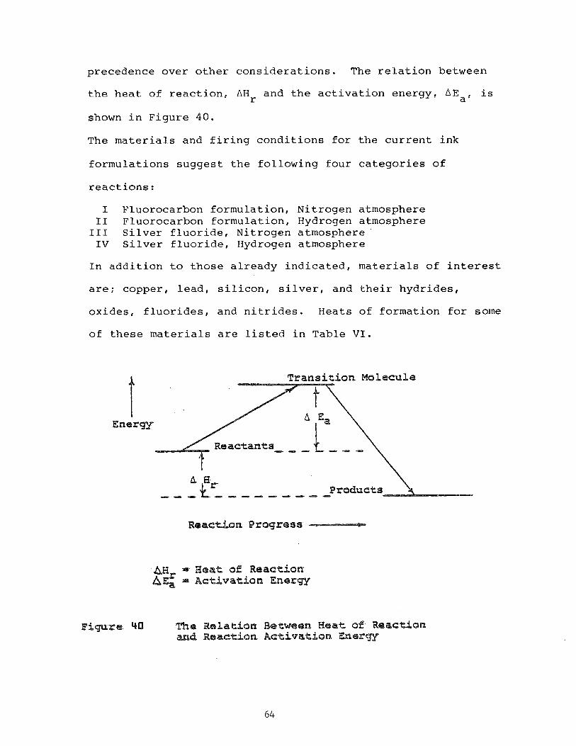
precedence over other considerations. The relation between
the heat of reaction. AHr and the activation energy. AEa, is
shown in Figure 40.
The materials and firing conditions for the current ink
formulations suggest the following four categories of
reactions:
I Fluorocarbon formulation, Nitrogen atmosphere I1 Fluorocarbon formulation, Hydrogen atmosphere I11 Silver fluoride, Nitrogen atmosphere '
IV Silver fluoride, Hydrogen atmosphere
In addition to those already indicated, materials of interest
are; copper, lead, silicon, silver, and their hydrides,
oxides, fluorides, and nitrides. Heats of formation for some
of these materials are listed in Table VI.
Energy
F i g u r e qQI
Transi t ion Molecule
A E3 Products - - C' - - d - - - - -
AHx = Heat of Reaction h E a = Activation Energy
T&te Relation B e t w e e n Heat of Reacdon and Reaction Activation =ergV
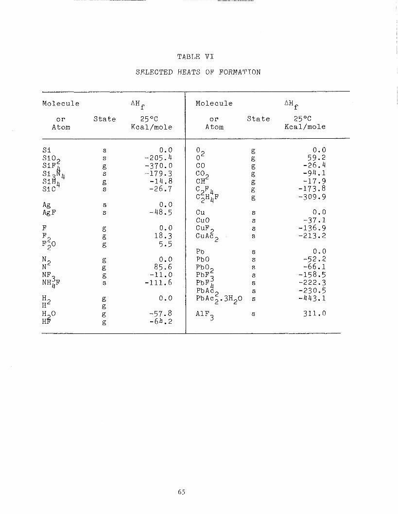
TABLE V I
SELECTED HEATS OF FORMATION
Molecu le AHp.
S i S i 0 2 S i F
S i C
Ag Ag F
F
NF3 NH4F
H2 H
Molecu le AHf
o r S t a t e 25 O C
Atom Kcal /mole
Cu S
cuo S
CuF2 s CuAc2 s
o r S t a t e 25OC Atom Kcal /mole
Pb s Pb 0 s Pb02 s PbF s PbF4 s PbAc2 s PbAc2.3H20 s
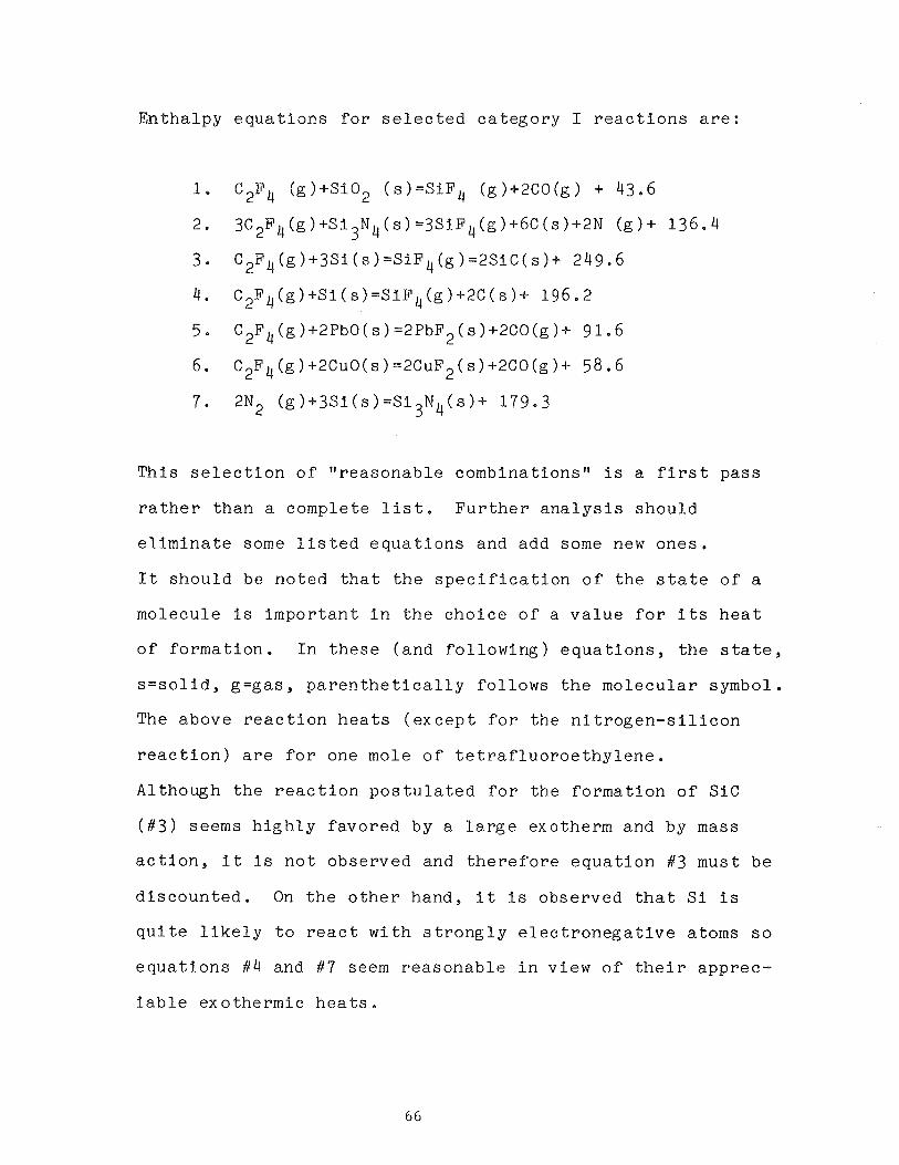
E n t h a l p y e q u a t i o n s f o r s e l e c t e d c a t e g o r y I r e a c t i o n s a r e :
T h i s s e l e c t i o n o f " r e a s o n a b l e c o m b i n a t i o n s u i s a f i r s t p a s s
r a t h e r t h a n a comple t e l i s t . F u r t h e r a n a l y s i s s h o u l d
e l i m i n a t e some l i s t e d e q u a t i o n s and add some new o n e s .
I t s h o u l d be n o t e d t h a t t h e s p e c i f i c a t i o n o f t h e s t a t e o f a
m o l e c u l e i s i m p o r t a n t i n t h e c h o i c e o f a v a l u e f o r i t s h e a t
o f f o r m a t i o n . I n t h e s e ( a n d f o l l o w i n g ) e q u a t i o n s , t h e s t a t e ,
s = s o l i d , g = g a s , p a r e n t h e t i c a l l y f o l l o w s t h e m o l e c u l a r symbol .
The above r e a c t i o n h e a t s ( e x c e p t f o r t h e n i t r o g e n - s i l i c o n
r e a c t i o n ) a r e f o r one mole o f t e t r a f l u o r o e t h y l e n e .
Al though t h e r e a c t i o n p o s t u l a t e d f o r t h e f o r m a t i o n o f SIC
( # 3 ) seems h i g h l y f a v o r e d by a l a r g e exotherm and by mass
a c t i o n , i t i s n o t o b s e r v e d and t h e r e f o r e e q u a t i o n #3 must b e
d i s c o u n t e d . On t h e o t h e r hand , i t i s o b s e r v e d t ha t S i i s
q u i t e l i k e l y t o r e a c t w i t h s t r o n g l y e l e c t r o n e g a t i v e a toms s o
e q u a t i o n s # 4 and #7 seem r e a s o n a b l e i n v i ew o f t h e i r a p p r e c -
i a b l e e x o t h e r m i c h e a t s .
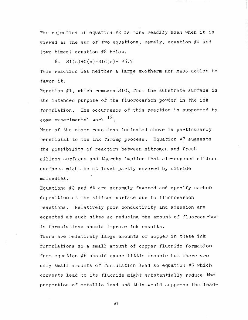
The r e j e c t i o n o f e q u a t i o n #3 i s more r e a d i l y s e e n when i t i s
viewed a s t h e sum o f two e q u a t i o n s , namely, e q u a t i o n #4 a n d
( two t i m e s ) e q u a t i o n #8 below,
T h i s r e a c t i o n h a s n e i t h e r a l a r g e exo the rm n o r mass a c t i o n t o
f a v o r i t .
R e a c t i o n #1, which removes S i 0 2 from t h e s u b s t r a t e s u r f a c e i s
t h e i n t e n d e d p u r p o s e o f t h e f l u o r o c a r b o n powder i n t h e i n k
f o r m u l a t i o n . The o c c u r r e n c e o f t h i s r e a c t i o n i s s u p p o r t e d by
12 some e x p e r i m e n t a l work
None o f t h e o t h e r r e a c t i o n s i n d i c a t e d above i s p a r t i c u l a r l y
b e n e f i c i a l t o t h e i n k f i r i n g p r o c e s s . E q u a t i o n #7 s u g g e s t s
t h e p o s s i b i l i t y o f r e a c t i o n between n i t r o g e n and f r e s h
s i l i c o n s u r f a c e s and t h e r e b y i m p l i e s t h a t a i r - e x p o s e d s i l i c o n
s u r f a c e s m i g h t b e a t l e a s t p a r t l y c o v e r e d by n i t r i d e
m o l e c u l e s .
E q u a t i o n s #2 and #4 a r e s t r o n g l y f a v o r e d and s p e c i f y c a r b o n
d e p o s i t i o n a t t h e s i l i c o n s u r f a c e due t o f l u o r o c a r b o n
r e a c t i o n s . R e l a t i v e l y poor c o n d u c t i v i t y and a d h e s i o n a r e
e x p e c t e d a t s u c h s i t e s s o r e d u c i n g t h e amount o f f l u o r o c a r b o n
i n f o r m u l a t i o n s s h o u l d improve i n k r e s u l t s . There a r e r e l a t i v e l y l a r g e amounts o f c o p p e r i n t h e s e i n k
f o r m u l a t i o n s s o a small amount o f c o p p e r f l u o r i d e f o r m a t i o n
from e q u a t i o n #6 s h o u l d c a u s e l i t t l e t r o u b l e b u t t h e r e a r e
o n l y s m a l l amounts o f f o r m u l a t i o n l e a d s o e q u a t i o n #5 w h i c h
c o n v e r t s l e a d t o i t s f l u o r i d e m i g h t s u b s t a n t i a l l y r e d u c e t h e
p r o p o r t i o n o f m e t a l l i c l e a d and t h i s would s u p p r e s s t h e l e a d -
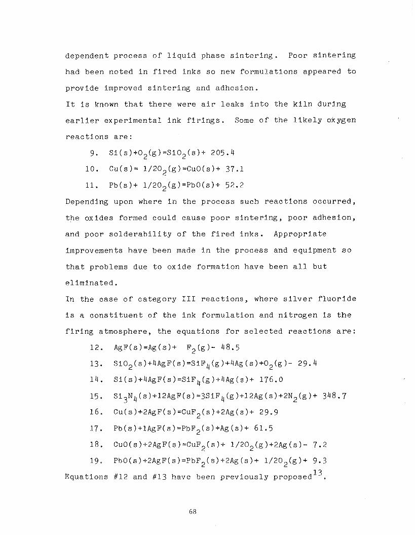
d e p e n d e n t p r o c e s s o f l i q u i d p h a s e s i n t e r i n g . Poor s i n t e r i n g
had been n o t e d i n f I r e d i n k s s o new f o r m u l a t i o n s a p p e a r e d t o
p r o v i d e improved s i n t e r i n g and a d h e s i o n .
I t i s known t h a t t h e r e were a i r l e a k s i n t o t h e k i l n d u r i n g
e a r l i e r e x p e r i m e n t a l i n k f i r i n g s . Some o f t h e l i k e l y oxygen
r e a c t i o n s a r e :
9. S i ( s ) + 0 2 ( g ) = S i 0 2 ( s ) + 205.4
1 0 . C u ( s ) = 1 / 2 0 2 ( g ) = C u O ( s ) + 37.1
11. P b ( s ) + 1 / 2 0 2 ( g ) = P b O ( s ) + 52.2
Depending upon where i n t h e p r o c e s s s u c h r e a c t i o n s o c c u r r e d ,
t h e o x i d e s formed c o u l d c a u s e p o o r s i n t e r i n g , p o o r a d h e s i o n ,
and p o o r s o l d e r a b i l i t y o f t h e f i r e d i n k s . A p p r o p r i a t e
improvements h a v e been made i n t h e p r o c e s s and equipment s o
t h a t p roblems due t o o x i d e f o r m a t i o n h a v e been a l l b u t
e l i m i n a t e d .
I n t h e c a s e o f c a t e g o r y I11 r e a c t i o n s , where s i l v e r f l u o r i d e
i s a c o n s t i t u e n t o f t h e i n k f o r m u l a t i o n and n i t r o g e n i s the
f i r i n g a t m o s p h e r e , t h e e q u a t i o n s f o r s e l e c t e d r e a c t i o n s a r e :
1 2 . A g F ( s ) = A g ( s ) + F 2 ( g ) - 48.5
13. Si02(s)+4AgF(s)=SiF4(g)+4Ag(s)+02(g)- 29.4
1 4 . Si(s)+4AgF(s)=SiF4(g)+4~g(s)+ 176.0
15. Si3N4(s)+12AgF(s)=3SiF4(g)+12Ag(s)+2N2(g)+ 348.7
16 . Cu(s)+2AgF(s)=CuF2(s)+2Ag(s)+ 29.9
17. ~b(s)+l~g~(s)=~b~~(s)+Ag(s)+ 61.5
1 8 . CuO(s )+2AgF(s )=CuF2(s )+ l / 2 0 2 ( g ) + 2 A g ( s ) - 7.2
19 . PbO(s)+2~gF(s)=PbF~(s)+2~g(s)+ 1 / 2 0 2 ( g ) + 9 .3
13 E q u a t i o n s #12 and #13 have been p r e v i o u s l y p roposed .
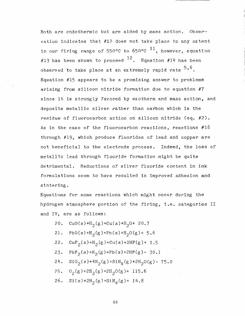
Both a r e endo the rmic b u t a r e a i d e d by mass a c t i o n . Obser -
v a t i o n i n d i c a t e s t h a t #12 does n o t t a k e p l a c e t o any ex t e n t
i n o u r f i r i n g r a n g e o f 55OoC t o 650°C 11, however, e q u a t i o n
#13 h a s been shown t o proceed 12. E q u a t i o n #14 h a s been
obse rved t o t a k e p l a c e a t an e x t r e m e l y r a p i d r a t e 5 , 6
E q u a t i o n #15 a p p e a r s t o be a p romis ing answer t o problems
a r i s i n g from s i l i c o n n i t r i d e f o r m a t i o n due t o e q u a t i o n #7
s i n c e i t i s s t r o n g l y f a v o r e d by exotherm and mass a c t i o n , and
d e p o s i t s m e t a l l i c s i l v e r r a t h e r t h a n ca rbon which i s t h e
r e s i d u e o f f l u o r o c a r b o n a c t i o n on s i l i c o n n i t r i d e ( e q . # 2 ) .
A s i n t h e c a s e o f t h e f l u o r o c a r b o n r e a c t i o n s , r e a c t i o n s #16
th rough #19, which produce f l u o r i d e s o f l e a d and copper a r e
n o t b e n e f i c i a l t o t h e e l e c t r o d e p r o c e s s . Indeed , t h e l o s s o f
m e t a l l i c l e a d th rough f l u o r i d e f o r m a t i o n m i g h t be q u i t e
d e t r i m e n t a l . Reduc t ions o f s i l v e r f l u o r i d e c o n t e n t i n i n k
f o r m u l a t i o n s seem t o have r e s u l t e d i n improved a d h e s i o n a n d
s i n t e r i n g . E q u a t i o n s f o r some r e a c t i o n s which migh t o c c u r d u r i n g t h e
hydrogen a tmosphere p o r t i o n o f t h e f i r i n g , i . e . c a t e g o r i e s I1
and I V , a r e as f o l l o w s :
20. ~ u 0 ( s ) + H ~ ( g ) = C u ( s ) + H ~ O + 20.7
21. Pbo(s)+~~(g)=-~b(s)+~~o(g)+ 5.6
22. CuF2(s)+H2(g)=Cu(s)+2HF(g)+ 1 . 5
23. PbF2(s)+H2(g)=Pb(s)+2HF(g)- 30.1
24. Si02(s)+4H2(g)+SiH4(g)+2H20(g)- 75.0
25. 0 2 ( g ) + 2 H 2 ( g ) = 2 H 2 0 ( g ) + 115.6
26. S i ( s ) + 2 H 2 ( g ) = S i H 4 ( g ) + 14 .8
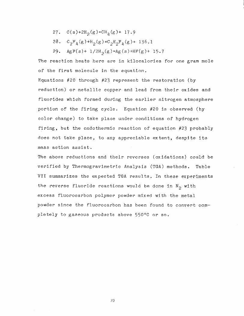
27. C ( s ) + 2 H 2 ( g ) = C H 4 ( g ) + 17 .9
28. C2F4(g)+H2(g)=C2H2F4(g)+ 1 3 6 - 1
29. AgF(s )+ 1/2H2(g)=Ag ( s ) + H F ( g ) + 15 .7
The r e a c t i o n h e a t s h e r e a r e i n k i l o c a l o r i e s f o r one gram mole
o f t h e f i r s t m o l e c u l e i n t h e e q u a t i o n .
E q u a t i o n s # 2 0 t h r o u g h #23 r e p r e s e n t t h e r e s t o r a t i o n ( b y
r e d u c t i o n ) o r m e t a l l i c c o p p e r and l e a d f rom t h e i r o x i d e s a n d
f l u o r i d e s which formed d u r i n g t h e e a r l i e r n i t r o g e n a t m o s p h e r e
p o r t i o n o f t h e f i r i n g c y c l e . E q u a t i o n #20 i s o b s e r v e d ( b y
c o l o r c h a n g e ) t o t a k e p l a c e unde r c o n d i t i o n s o f hyd rogen
f i r i n g , h u t t h e e n d o t h e r m i c r e a c t i o n o f e q u a t i o n #23 p r o b a b l y
d o e s n o t t a k e p l a c e , t o any a p p r e c i a b l e e x t e n t , d e s p i t e i t s
mass a c t i o n a s s i s t .
The above r e d u c t i o n s and t h e i r r e v e r s e s ( o x i d a t i o n s ) c o u l d b e
v e r i f i e d by T h e r m o g r a v i m e t r i c A n a l y s i s (TGA) methods . T a b l e
V I I summarizes t h e e x p e c t e d TGA r e s u l t s . I n these e x p e r i m e n t s
t h e r e v e r s e f l u o r i d e r e a c t i o n s would b e done i n N2 w i t h
e x c e s s f l u o r o c a r b o n po lymer powder mixed w i t h t h e m e t a l
powder s i n c e t h e f l u o r o c a r b o n h a s been found t o c o n v e r t com-
p l e t e l y t o g a s e o u s p r o d u c t s above 550°C o r s o .
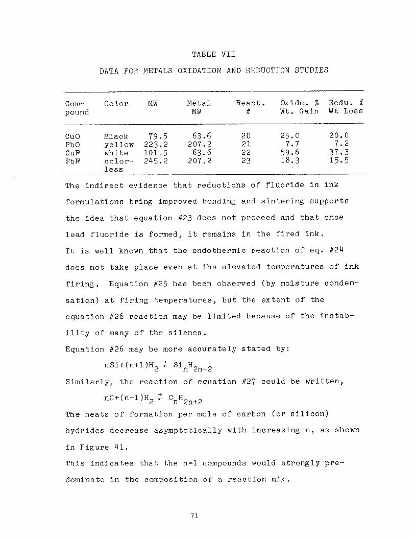
TABLE V I I
DATA FOR METALS OXIDATION AND REDUCTION STUDIES
Corn- C o l o r MW Meta l R e a c t . Oxide. % Redu. % pound MW # W t . Ga in W t Loss
CuO Black 79.5 63.6 20 25.0 20.0 Pb 0 y e l l o w 223.2 207.2 21 7.7 7.2 CuF w h i t e 101.5 63.6 22 59.6 37.3 PbF c o l o r - 245.2 207.2 23 18.3 15.5
less
The i n d i r e c t e v i d e n c e t h a t r e d u c t i o n s o f f l u o r i d e i n i n k
f o r m u l a t i o n s b r i n g improved bonding and s i n t e r i n g s u p p o r t s
t h e i d e a t h a t e q u a t i o n #23 d o e s n o t p r o c e e d and t h a t o n c e
l e a d f l u o r i d e i s formed, i t r e m a i n s i n t h e f i r e d i n k .
I t i s w e l l known t h a t t h e e n d o t h e r m i c r e a c t i o n o f e q . #24
d o e s n o t t a k e p l a c e even a t t h e e l e v a t e d t e m p e r a t u r e s o f i n k
f i r i n g . E q u a t i o n #25 h a s been o b s e r v e d ( b y m o i s t u r e conden-
s a t i o n ) a t f i r i n g t e m p e r a t u r e s , b u t t h e e x t e n t o f t h e
e q u a t i o n #26 r e a c t i o n may be l i m i t e d b e c a u s e o f t h e i n s t a b -
i l i t y o f many o f t h e s i l a n e s .
E q u a t i o n #26 may b e more a c c u r a t e l y s t a t e d by:
S i m i l a r l y , t h e r e a c t i o n o f e q u a t i o n #27 c o u l d b e w r i t t e n ,
The h e a t s o f f o r m a t i o n p e r mole o f c a r b o n ( o r s i l i c o n )
h y d r i d e s d e c r e a s e a s y m p t o t i c a l l y w i t h i n c r e a s i n g n , a s shown
i n F i g u r e 41.
T h i s i n d i c a t e s t h a t t h e n = l compounds would s t r o n g l y p r e -
domina te i n t h e c o m p o s i t i o n o f a r e a c t t o n mix.
The c l a s s i c p r o c e d u r e f o r t h e p r o d u c t i o n o f s i l a n e s u s i n g
magnesium s i l i c i d e i n H 2 and H C ~ ' ~ . r e s u l t s i n 40% SiH, 30%
Si2H6,15% S13H8, 10% Si4H10 and 5% h i g h e r s i l a n e s 17 . N o n - v o l a t i l e s i l i c o n h y d r i d e po lymers which i n c l u d e an
u n s a t u r a t e d bond h a v e a l s o been p repa red17 . These may a r i s e
from,
-t nS i + nH2 + (SiH2),
Condensed h y d r i d e po lymers o r homologues o f s i l i c o n ( s i l a n e s )
o r ca rbon ( a l k a n e s ) d e p o s i t e d on t h e s i l i c o n s u b s t r a t e would
be e x p e c t e d t o a f f e c t a d v e r s e l y t h e p h y s i c a l and e l e c t r i c a l
p r o p e r t i e s o f f i r e d i n k s .
On e x a m i n a t i o n o f t h e r e a c t i o n e n t h a l p i e s and mass a c t i o n
e f f e c t s i t a p p e a r s l i k e l y t h a t hydrogen d o e s r e a c t , d u r i n g
f i r i n g , w i t h r e s i d u a l t e t r a f l u o r o e t h y l e n e ( e q . # 2 8 ) i n
c a t e g o r y I1 o r w i t h s i l v e r f l u o r i d e ( e q . #29 ) i n c a t e g o r y I V .
The hydrogen a t m o s p h e r e p h a s e o f f i r i n g h a s been a s s o c i a t e d
w i t h f r e q u e n t random i n c i d e n t s o f v e r y p o o r i n k a d h e s i o n
u s i n g i n k s which p r e v i o u s l y g a v e e x c e l l e n t bond ing . I n some
c a s e s , i n k samples which were w e l l bonded ( b u t somewhat
o x i d i z e d ) d u r i n g t h e n i t r o g e n f i r i n g showed no bonding a f t e r
hydrogen f i r i n g . One p o s s i b l e e x p l a n a t i o n i s t h a t bonding
s i t e s on t h e s i l i c o n s u b s t r a t e a r e c h e m i c a l l y a t t a c k e d by t h e
HF g e n e r a t e d a c c o r d i n g t o e q u a t i o n s #22 and #29 i n hydrogen
f i r i n g .
A r e d u c t i o n o f t h e t e m p e r a t u r e o f t h e i n k sample d u r i n g
hydrogen f i r i n g g i v e s a n improvement i n i n k bond ing , which
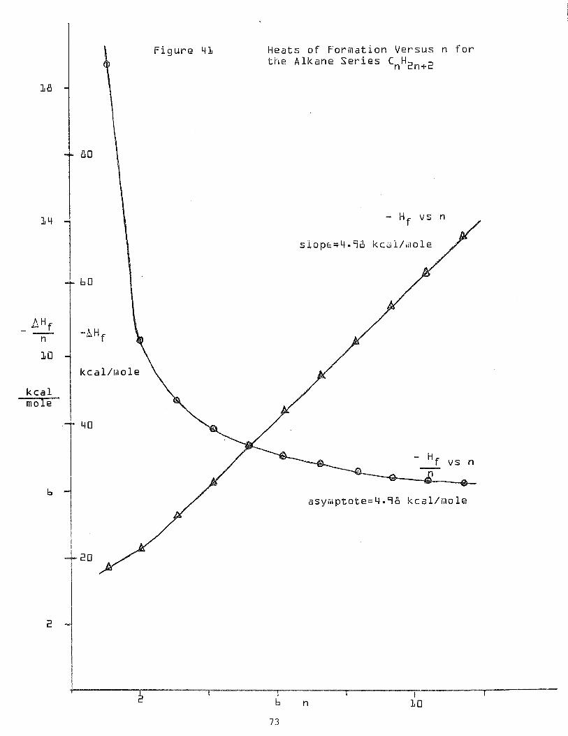
k c a l m o l e
F i g u r e 4 1 H e a t s o f F o r m a t i o n V e r s u s n f o r t h e A l k a n e S e r i e s CnHZnc2
c o u l d be a t t r i b u t e d t o a r e d u c t i o n i n t h e e x t e n t o f e q u a t i o n s
tY22 and #29,
Another h y p o t h e s i s i s t h e o c c u p a t i o n o f d a n g l i n g e l e c t r o n
bonds on s i l i c o n s u r f a c e s by hyd rogen o r p o s s i b l y t h e
d i s p l a c e m e n t o f m e t a l a toms by hyd rogen ( s e c t i o n 8 . 0 ) . These
p r e l i m i n a r y a p p l i c a t i o n s o f s i m p l e c h e m i c a l i d e a s have
p o i n t e d t o some f r u i t f u l d i r e c t i o n s f o r e x p e r i m e n t a l work
aimed a t improvement o f i n k m a t e r i a l s and p r o c e s s e s . I n
p a r t i c u l a r , p r o g r e s s i v e f l u o r i d e r e d u c t i o n s and m i l d e r
hyd rogen t r e a t m e n t s , which were s u g g e s t e d by the rmochemica l
and mass a c t i o n c o n s i d e r a t i o n s , p roved q u i t e b e n e f i c i a l t o
t h e m e c h a n i c a l p r o p e r t i e s o f t h e i n k s y s t e m .
I n c o n s i s t e n c y o f r e s u l t s s t i l l p l a g u e s t h e i n k f o r m u l a t i o n s
c o n t a i n i n g f l u o r o c a r b o n powder, and e a r l y s t u d i e s o f i n k
e l e c t r i c a l p e r f o r m a n c e i n d i c a t e a need f o r i n c r e a s e d
knowledge o f t h e c h e m i s t r y o f t h e s e i n k s y s t e m s .
To t h i s end , t h e work o f t h i s r e p o r t s h o u l d be expanded t o
i n c l u d e l i t e r a t u r e s e a r c h e s t o u n e a r t h more p o s s i b l e
r e a c t i o n s and p r o v i d e needed h e a t c a p a c i t i e s and a c t i v a t i o n
e n e r g i e s . E x p e r i m e n t a l work making u s e o f TGA and d i f f e r -
e n t i a l t h e r m a l a n a l y s i s (DTA) s h o u l d be i n c r e a s e d and i n
a d d i t i o n , t h e s i m p l e t h e o r e t i c a l t o o l s o f c h e m i c a l k i n e t i c s
and c h e m i c a l e q u i l i b r i u m s h o u l d be a p p l i e d t o t h e d e t e r m i n -
a t i o n o f t h e l i k e l y ex t e n t o f c a n d i d a t e r e a c t i o n s .
8.0 HYDROGEN CONCENTRATION PROFILING
Earlier experiences with hydrogen firing have shown that both
silver and copper lose their adhesion to silicon surfaces in
hydrogen ambients above a temperature of approximately 380°C.
In order to investigate this phenomenon a procedure was
sought which would allow determining the hydrogen concen-
tration profile in close proximity to the silicon surface.
Professor W.A. Lanford S.U.N.Y., Albany, N.Y., kindly
consented to examine a set of "unknown" samples produced in
our laboratory utilizing the technique of resonant nuclear
reaction profiling. Figure 42 illustrates the method. The
equation for the nuclear reaction is shown in the line near
the top of the figure. The subscript on the left of the
elemental symbol denotes the atomic number of the element,
the superscript on the right of the symbol signifies the
atomic weights. When a nitrogen nucleus of precisely the
correct energy 6.385 Mev is incident upon a hydrogen nucleus,
the described reaction takes place. The reaction products,
carbon and helium, recoil energetically after the reaction in
addition to a 4.45 Mev gamma quantum.
dE 15 The rate of energy loss(-) of the energetic N nucleus in dX
silicon has been established at 1.5 ~ev/pm. This allows an
accurate calibration of the depth of the reaction when the
incident beam energy is known. The reaction is a resonance
reaction when the incident beam energy is known. The
reaction is a resonance reaction since the cross-section, 0 ,
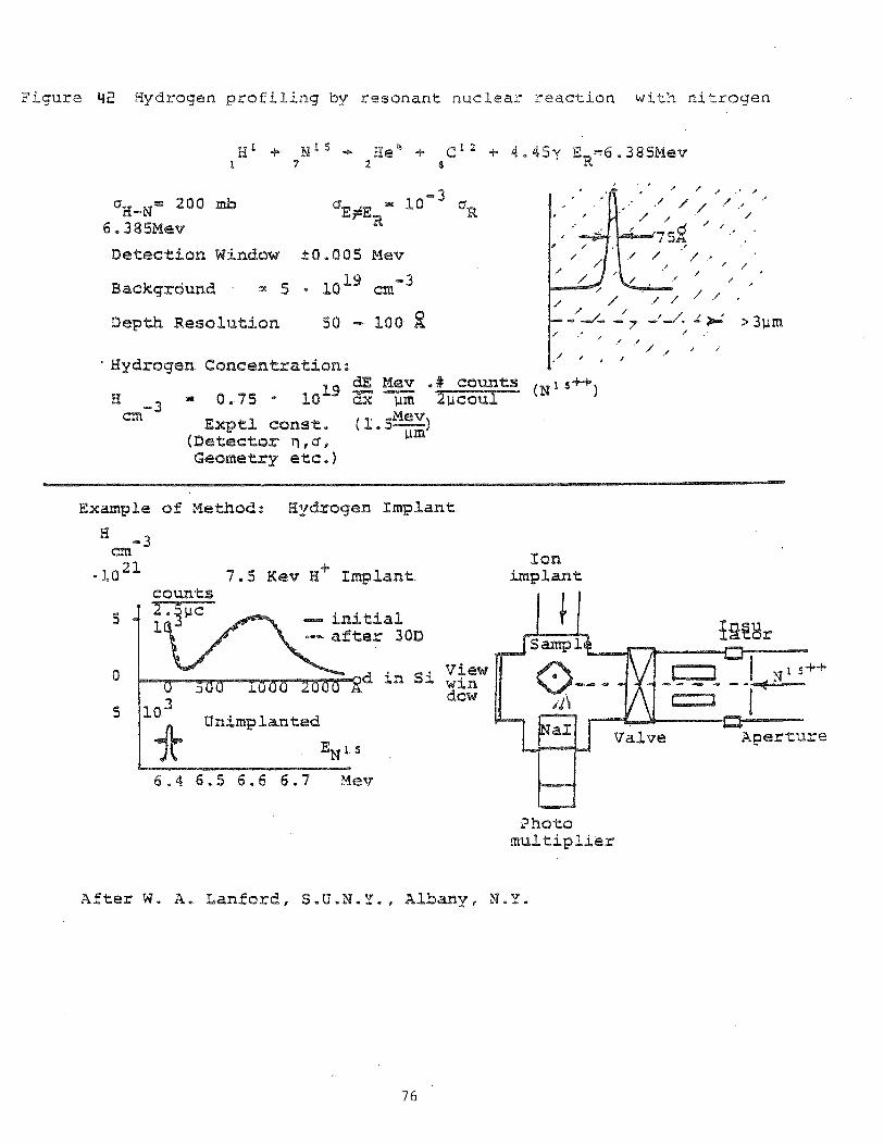
Figure 42 Hydrogen profiling by r e s o n a n t nuclear r e a c t i o n wit :? n i t r o g e n
Deteclion Window k0.005 Mev
Baekgrdund - - 5 - 10 19 cm-3
Depth Resolution ro -- LOO 2 :
, I i
' Hydrogen Concentrati~n: & Mev . (N "S++ - 0.75 * l o L 9 1 -3 m Mev Exptl const- (1-5--1
(Detector n , a, Pa
Geometry etc.)
Example sf Meaod: Bydrogen Implant
EI - 3 m Ion - 1021 7.5 Kev H* I w l a n t hplant
6 . 4 6 . 5 6 . 6 6 - 7 Mev
?hot0 paul t i p l i e r
After W. A . Lanford, S,U.N,Y., Albany, N - X .
a t t h e r e a c t i o n e n e r g y ER i s q u i t e l a r g e , 200 m i l l i b a r n s ,
whereas i t f a l l s t o 0=0,2mb o f f e n e r g y r e s o n a n c e ( o u t s i d e
t h e r e a c t i o n window). The r i g h t hand s i d e o f F i g u r e 42
i n d i c a t e s t h e s i l i c o n t h i c k n e s s e q u i v a l e n t o f t h e r e a c t i o n
window i s 75A, Which s p e c i f i e s t h e r e s o l u t i o n o f t h e method .
The e m p i r i c a l r e l a t i o n be tween hydrogen c o n c e n r a t i o n , number
o f c o u n t s and s i l i c o n t h i c k n e s s i s shown on t h e m i d d l e o f t h e
page i n f i g u r e 42.
The d i ag ram i n t h e l ower r i g h t o f t h e f i g u r e shows an
a p p l i c a t i o n t o a hydrogen i o n i m p l a n t a t i o n e x p e r i m e n t . The
hydrogen i o n i m p l a n t a t i o n beam e n t e r s t h e a p p a r a t u s f rom
above , imp inges on h e sample on t h e r o t a t a b l e c u b i c s a m p l e
h o l d e r . A 90° r o t a t i o n a l l o w s t h e sample t o be s t r u c k by t h e
N ~ ~ + beam. A s t h e r e a c t i o n s p roceed gamma q u a n t a a r e
c o l l e c t e d by t h e N a I c r y s t a l o f t h e s c i n t i l l a t i o n c o u n t e r .
The c u r v e s on t h e l e f t i l l u s t r a t e t h e e x p e r i m e n t a l r e s u l t s ,
i n c l u d i n g t h e i n s i g n i f i c a n t s h i f t i n hydrogen c o n c e n t r a t i o n
a f t e r a 30 d a y d w e l l t i m e .
The i n i t i a l e x p e r i m e n t u t i l i z e d s o l a r c e l l wafers w i t h a
s e r i e s of h e a t t r e a t m e n t s as f o l l o w s :
Samples 1 and 2 C o n t r o l s ( n o t r e a t m e n t )
3 and 4 60o0C 10 m i n u t e s , N 2 , f l o w
5 and 6 600°C 1 0 m i n u t e s , CO f l o w
7 and 8 600°C 1 0 m i n u t e s , H2 f l o w
9 and 10 600°C 10 m i n u t e s , F31 Cu, CO f l o w
11 and 1 2 600°C 1 0 m i n u t e s , F31 Cu, H2 f l o w
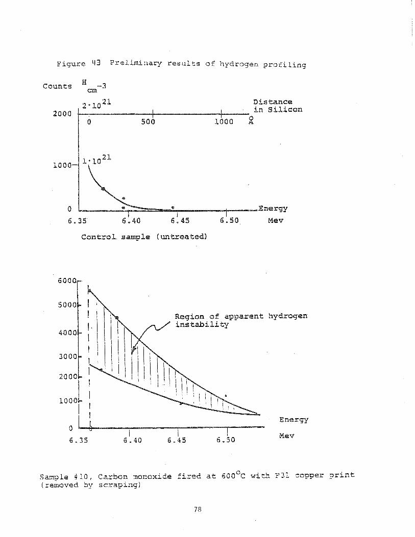
~ i ~ ~ ~ e L)3 F r s l i m i n a r y r e s u l t s of hydrogen p r o f i l i n g
Counts -3
Distance
2000 in Silicon
I 6.35 6.40 6 1 45 Mev
Control sample (untreated)
hydrogen
E n e r g
Mev
Sarnple *LO, Carbon rnonoxide f i r e d at 6 0 0 ~ ~ w i t h P 3 i copper print ( removed by scraping)
The samples 9 and 1 0 , s c r e e n e d w i t h F31, were s u b s e q u e n t l y
s c r a p e d w i t h a r a z o r b l a d e . The c o p p e r e l e c t r o d e was
removable w i t h some d i f f i c u l t y , Samples 11 and 1 2 were a l s o
s u b j e c t e d t o s c r a p i n g , b u t t h e e l e c t r o d e c o u l d e a s i l y b e
removed w i t h a t ongue d e p r e s s o r shaped wooden s t i c k . Whi le
t h e c o p p e r l a y e r s a p p e a r e d w e l l s i n t e r e d , none c o u l d p a s s t h e
S c o t c h t a p e t e s t .
S i n c e t h e n i t r o g e n beam i n c i d e n t upon t h e s ample i s
a p p r o x i m a t e l y 1 cm d i a m e t e r , a n a t t e m p t was made t o c l e a v e
wafers i n t o 4 1x1 cm s q u a r e s p r i o r t o s h i p m e n t . S i n c e w a f e r s
were c u t o f f a x i s , s c r i b e and b r e a k was u n s u c c e s s f u l ,
r e s u l t i n g i n oddshaped u n d e r s i z e d spec imens .
F i g u r e 43 shows two d a t a p l o t s from i n i t i a l r e s u l t s . The
c o n t r o l sample p l o t i s p r o v i d e d w i t h c o o r d i n a t e a x e s marked
w i t h p r a c t i c a l u n i t s . T h i s sample i s w e l l behaved. The
o t h e r p l o t i s anomalous showing a p o s s i b l e hydrogen
i n s t a b i l i t y . F u r t h e r work i s needed w i t h l a r g e r s amples t o
c l a r i f y t h e i n i t i a l r e s u l t s .
9 . 0 FIRING EXPERIMENTS
9 . 1 F u r n a c e C a l i b r a t i o n
Ev idence of drifting o f t h e t e m p e r a t u r e c o n t r o l chromel -
Alumel thermocouple l e d t o a r e c a l i b r a t i o n o f t h e f u r n a c e .
The p r o f i l e shown i n F i g u r e 4 4 r e s u l t e d from p r o b i n g t h e
f u r n a c e t u b e w i t h a P t - P t + 13% Rh the rmocoup le c o n n e c t e d
t o a d i g i t a l m i c r o v o l t meter. Only t h e e x i t p o r t i o n o f t h e
p r o f i l e e x t e n d i n g beyond t h e c e n t e r o f t h e f u r n a c e i s shown,
a s i t i s t h e r e g i o n o f m a j o r i n t e r e s t i n o u r e x p e r i m e n t a t i o n .
I t h a s been made a p a r t o f t h e e x p e r i m e n t a l p r o t o c o l t o g e t
t e m p e r a t u r e r e a d i n g s a t l e a s t a t t h e b e g i n n i n g and end o f
e a c h r u n w i t h t h e p l a t i n u m the rmocoup le and d i g i t a l m e t e r .
9 . 2 Gas Ambients
Dur ing f i r i n g t e s t s i t was found t h a t :
a ) n i t r o g e n f i r i n g r e s u l t e d i n s e v e r e l y o x i d i z e d c o p p e r
g r a i n s
b ) t h e p o s i t i o n o f s i l i c o n w a f e r s ( s t a n d i n g i n s l o t t e d b o a t
o r l y i n g f l a t ) had a b e a r i n g on t h e r e s u l t s
c ) t h e d u r a t i o n o f t h e s econd s t e p (hydrogen f l o w ) i n t h e two
s t e p f i r i n g was a f a c t o r i n t h e a d h e r e n c e o f t h e e l e c t r o d e
t o t h e s i l i c o n s u b s t r a t e .
S e v e r a l e x p l a n a t i o n s are p o s s i b l e f o r t h i s b e h a v i o r . Contam-
i n a t i o n o f t h e s o u r c e f l o w g a s e s was r u l e d o u t , s i n c e i t w a s
v e r i f i e d t h a t a l l n i t r o g e n p r o c u r e d , s i n c e f i r i n g f i r s t
commenced, was o i l pumped ( v s . w a t e r pumped), and n o o t h e r
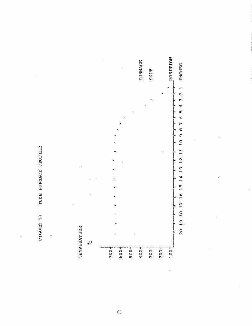
e v i d e n c e p o i n t e d i n t h a t d i r e c t i o n . However, back s t r e a m i n g ,
c o n v e c t i v e f l o w and t h e r e f o r e a i r c o n t a m i n a t i o n o f f u r n a c e
a tmosphe re i n t h e open e x i t q u a r t z t u b e was c o n s i d e r e d
l i k e l y . F u r t h e r , c o n t a m i n a t i o n o f f u r n a c e q u a r t z f u r n i t u r e
was a p o s s i b i l i t y and was t h e r e f o r e assumed. The f o l l o w i n g
s t e p s were t a k e n t o c o u n t e r t h e r e p o r t e d p rob lems .
1) Convec t ion and b a c k s t r e a m i n g were r educed by i n s e r t i o n o f
an a lumna l lwoolf l p lug i n t o t h e q u a r t z t u b e e x i t d u r i n g
f i r i n g . T h i s p l u g r e s t r i c t s t h e e x i t d i a m e t e r , b r e a k s up
t h e g a s s t r e a m i n t o a number o f s m a l l f i l a m e n t a r y s t r e a m s
and i n c r e a s e s t h e v e l o c i t y o f t h e s t r e a m s marked ly , t h e r e -
by r e d u c i n g b a c k d i f f u s i o n .
2 ) A l l q u a r t z f u r n i t u r e was t a k e n t o a p r o f e s s i o n a l g l a s s
shop f o r c l e a n i n g .
I t was found t h a t t h e h i g h e r t h e t e m p e r a t u r e o f t h e
hydrogen t r e a t m e n t , t h e more l i k e l y e l e c t r o d e s e p a r a t i o n
would o c c u r . A t t e m p e r a t u r e s below 3 8 0 ° C , t h e e f f e c t o f
hydrogen upon a d h e s i o n a p p e a r e d t o be min ima l . F o r t h i s
r e a s o n a f i r i n g p r o f i l e was d e v i s e d as shown i n F i g u r e 35.
While t h e r e was some c o n c e r n t h a t i n i t i a l o x i d a t i o n m i g h t
i m p a i r t h e f r i t m e t a l w e t t i n g p r o c e s s o f t h e c o p p e r *
g r a i n s , t h i s p roved t o b e a l e s s s i g n i f i c a n t f a c t o r f o r
t h e f o l l o w i n g r e a s o n : Dur ing t h e i n i t i a l f i r i n g p r o c e s s a
r e d u c i n g a tmosphe re i s produced i n t h e f u r n a c e by t h e
o r g a n i c c o n s t i t u a n t s o f t h e p a s t e v e h i c l e and b i n d e r .
T h i s m a t e r i a l i s removed and t r a n s p o r t e d away from t h e
f i r i n g s i t e . Only t h e n d o e s t h e c o p p e r g r a i n m a t r i x as
well as the lead frit metal become succeptible to
oxidation due to contamination, backstreaming and back-
diffusion of oxygen. While this can be reduced, as
discussed in the next section, the use of hydrogen during
the cooling phase of the firing cycle is helpful in main-
taining metallic surface properties and appearance.
The following cleaning procedure was used:
1) Bakeout at 570°C in air (burnout of organic chemicals,
convert metals to oxide, remove strains in quartz)
2) Soak in 30% hydrofluoric acid
3) Scrub with cheesecloth (in hydrofluoric acid)
4) Rinse in deionized water and dry
This cleaning procedure is routinely used by General Atomics
Corporation, San Diego.
A number of firing experiments were done after the furnace
quartz ware was returned to service. The exit baffle dif-
fuser plug allowed making pure nitrogen flow firing without
showing visible oxidation. However, neither sintering
activity nor adherence were significantly improved. Further,
the reproducibility of results with specific pastes either in
separate firings or one firing experiments is poor. Because
firings are done in a semi-closed system, it was felt that
relocation of the equipment might be beneficial. The
location of the firing equipment until June 1981, approxi-
amtely two miles from the Pacific Ocean coast, is within
marine layer weather influence. Of particular concern is the
possible major contamination with aerosol salt powders. Some
evidence of t h i s was seen i n t h e sodium yellow f l i c k e r of t h e
hydrogen e f f l u e n t of t h e e x i t flame c u r t a i n . I t was the re -
f o r e decided t o r e l o c a t e t h e f i r i n g f a c i l i t y t o t h e E lec t r ink
p l a n t approximately 9 miles from the P a c i f i c coas t and more
under d e s e r t weather inf luence .
9.3 Copper Pas te Electrode F i r i n g Experiments
Based upon t h e o r e t i c a l analyses and TGA/DTA experiments t h e
s i l v e r f l u o r i d e content of copper pas tes was sharply reduced.
Previous s i l v e r f l u o r i d e add i t ives t o copper pas tes were
approximately 5 weight percent . Copper p a s t e F20 was
compounded with 0.7 wt.8 s i l v e r f luor ide .
F i r i n g experiments were ca r r i ed out with t h i s p a s t e on eleven
s i l i c o n s u b s t r a t e s with sur faces ranging from l i g h t l y etched
t o a s lapped (#600 mesh s i l i c o n ca rb ide ) . The p r i n t s were
d r i ed on a h o t p l a t e a t 130°C f o r 5 minutes. During f i r i n g
t h e temperature was increased moderately i n a number of
s t e p s , i n a n i t rogen flow, up t o the peak temperature. The
f i r i n g temperature was then reduced by t r anspor t ing the
wafers t o cooler p o r t i o n s of t h e furnace. The temperature
was reduced t o 340°C before hydrogen was added t o t h e
ni t rogen stream (approximately 50% hydrogen). This r e s u l t e d
i n adherent e l ec t rodes , passing the Scotch tape t e s t , bu t
showing a somewhat undersintered s t r u c t u r e .
Three views a r e shown of t h i s e l ec t rode s t r u c t u r e ( ~ 2 0 ) .
Figure 46 i s an SEM photomicrograph a t 2000X giv ing an
average g ra in s i z e of approximately 0.5 P m . Well s i n t e r e d
structures will give grain diameters of the order of 3-4 m.
Also the amount of open area in the grain matrix and lack of
continuous paths (lack of coherence) is an indication of
undersintering. This can be seen better in Figure 47 and 48
with a magnification of 10,000X and 6,750X respectively.
Figure 48 is an edge-on view of a cleaved substrate with
electrode. The copper-silicon eutectic phase characterized
by large broad based spikes, discussed previously 18 is not
apparent on this view. Based on various experiments and
reports in the literature, it appears that hydrogen tends to
form a strong bond with silicon, displacing metal atoms at
the surface. This caused us to change the gas flow sequence
during firing so that hydrogen is introduced later, at a time
when the specimen temperature is less than 380°C. This
modified firing procedure is shown in Figure 45. The purpose
of the hydrogen is to reduce any copper or lead oxides that
may have formed in previous processing. The disadvantage of
this procedure is as follows: Preexisting oxides on the
copper grain surfaces and on the lead grains may discourage
or prevent the liquid lead from wetting the copper grains.
This will in turn reduce the extent of the sintering process
and result in a smaller grain size and a less coherent
structure. This is believed to be the explanation for the
observed microstructure in the above figures. Some
mitigation of this problem should occur because of the
reducing effect of the organic vehicle of the inks.
While the affinity for dangling electron bonds on silicon
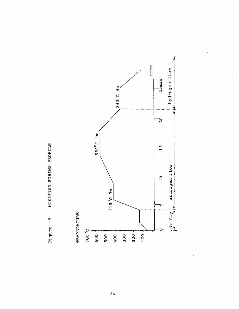
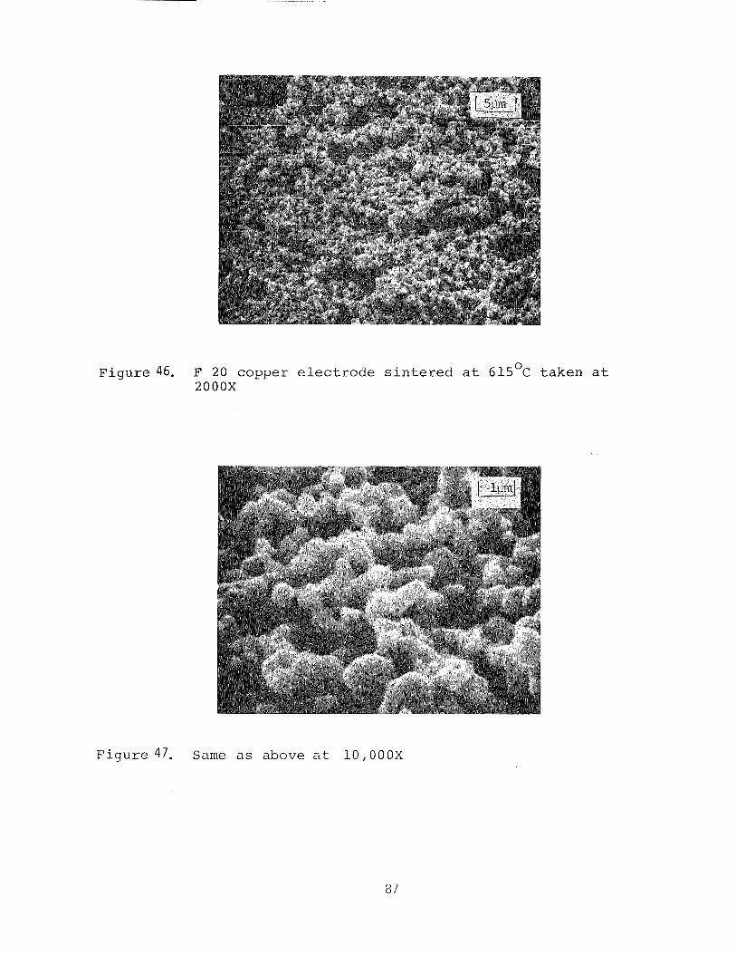
F i g u r e 46. F 20 copper e l e c t r o d e s i n t e r e d a t 6 1 5 O ~ t a k e n a t 2000X
F i g u r e 47. Same as above a t 10,000X
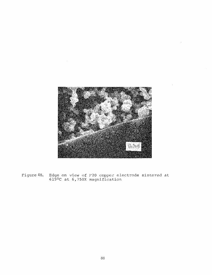
F i g u r e 4 8 . Edge o n view o f F20 coppe r e l e c t r o d e s i n t e r e d a t 615OC a t 6,750X m a g n i f i c a t i o n
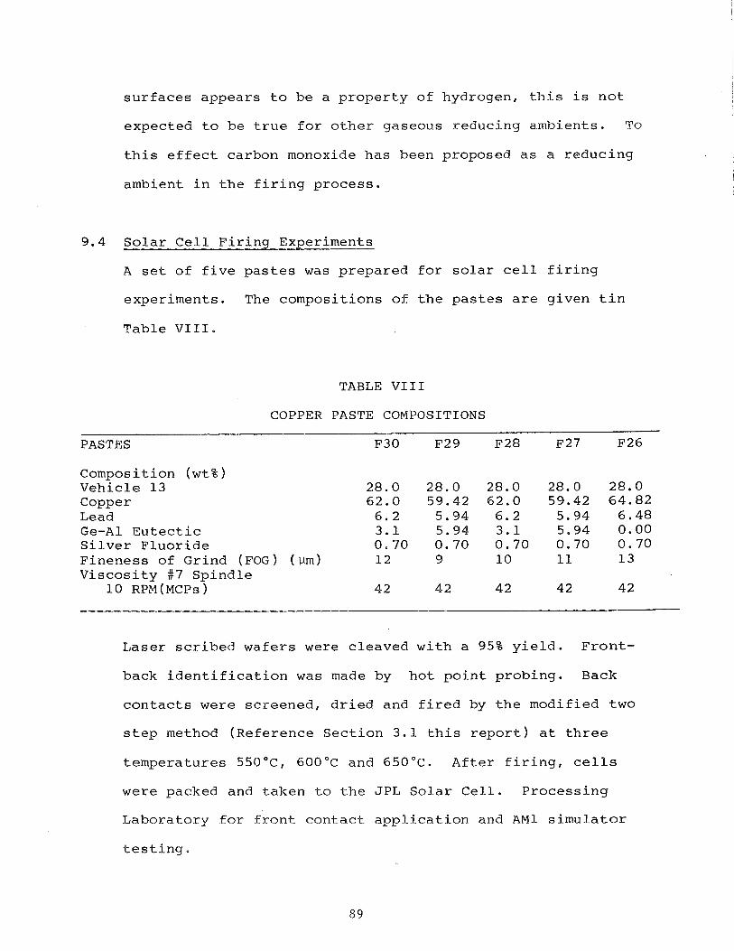
s u r f a c e s a p p e a r s t o b e a p r o p e r t y o f hydrogen, t h i s is n o t
expec ted t o b e t r u e f o r o t h e r gaseous reduc ing ambien t s . To
t h i s e f f e c t carbon monoxide h a s been proposed a s a r e d u c i n g
ambient i n t h e f i r i n g p r o c e s s .
9 .4 S o l a r C e l l F i r i n g Experiments
A se t o f f i v e p a s t e s was p r e p a r e d f o r s o l a r c e l l f i r i n g
exper iments . The compos i t ions o f t h e p a s t e s a r e g i v e n t i n
T a b l e V I I I .
TABLE V I I I
COPPER PASTE COMPOSITIONS
PASTES F30 F29 F28 F27 F26
Composit ion ( w t 8 ) V e h i c l e 13 28.0 28.0 28.0 28.0 28 .0 Copper 62 .0 59.42 62.0 59.42 64.82 Lead 6 . 2 5.94 6 .2 5.94 6 . 4 8 G e - A 1 E u t e c t i c 3 . 1 5.94 3 . 1 5.94 0 .00 S i l v e r F l u o r i d e 0 .70 0 .70 0 .70 0.70 0 .70 F i n e n e s s o f Gr ind ( F O G ) ( v m ) 12 9 10 11 1 3 V i s c o s i t y #7 S p i n d l e
1 0 RPM(MCPS) 42 42 42 42 42
L a s e r s c r i b e d w a f e r s were c l e a v e d w i t h a 95% y i e l d . F r o n t -
back i d e n t i f i c a t i o n was made by h o t p o i n t p r o b i n g . Back
c o n t a c t s were s c r e e n e d , d r i e d and f i r e d by t h e modi f i ed t w o
s t e p method ( ~ e f e r e n c e S e c t i o n 3 . 1 t h i s r e p o r t ) a t t h r e e
t e m p e r a t u r e s 550°C, 600°C and 6 5 0 " ~ . A f t e r f i r i n g , c e l l s
w e r e packed and t a k e n t o t h e J P L S o l a r C e l l . P r o c e s s i n g
L a b o r a t o r y f o r f r o n t c o n t a c t a p p l i c a t i o n and AM1 s i m u l a t o r
t e s t i n g ,
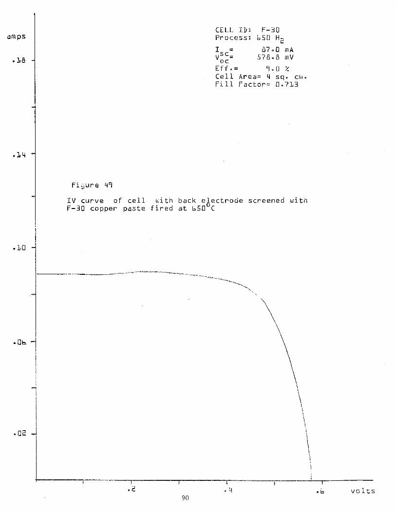
a m p s
. L B
.LLi
.LO
SO2
CELL ID: F-30 P r o c e s s : b 5 0 Hz
I -- 8'9.0 m A v"==
oc 578.8 m V E P f = = 79.B % C e l l Area= 4 sq. cr~i. F i l l F a c t o r = 0.7L3
I V c u r v e o f c e l l b i t n b a c k e l e c t r o d e s c r e e n e d w i t h F-30 c o p p e r p a s t e f i r e d a t b50°C
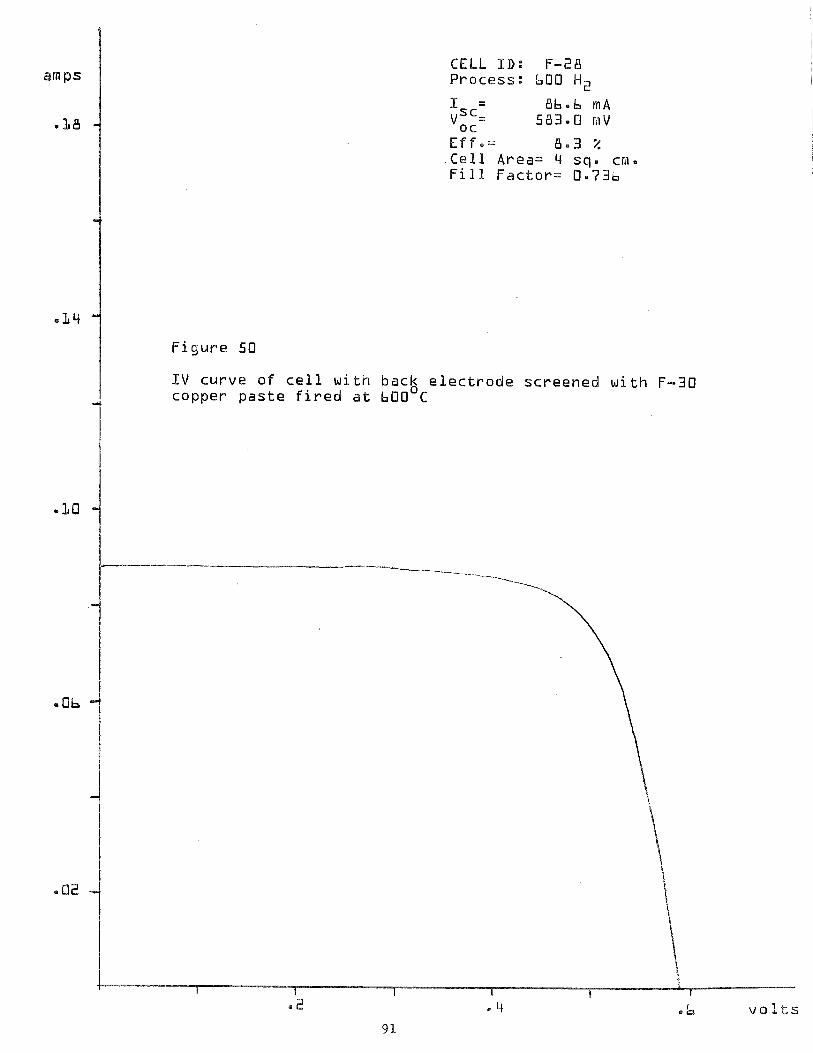
amps
l B
CELL I D : F-28 P rocess : 600 Hz
I = 86-6 m A vS6=
oc 583.0 nV
E f f e = 8 - 3 % C e l l Area= 4 sq. cn. F i l l F a c t o r = 0.736
I V c u r v e o f c e l l w i t h back e l e c t r o d e s c r e e n e d w i t h F-30 copper p a s t e f i r e d a t 600 C
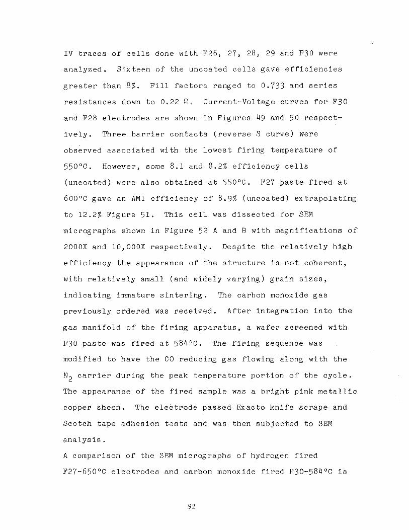
I V t r a c e s o f c e l l s done w i t h F26, 27, 28, 29 and F30 were
a n a l y z e d . S i x t e e n o f t h e u n c o a t e d c e l l s g a v e e f f i c i e n c i e s
g r e a t e r t h a n 8 % . F i l l f a c t o r s r anged t o 0 .733 and s e r i e s
r e s i s t a n c e s down t o 0.22 Q . C u r r e n t - V o l t a g e c u r v e s f o r F30
and F28 e l e c t r o d e s a r e shown i n F i g u r e s 49 and 50 r e s p e c t -
i v e l y . T h r e e b a r r i e r c o n t a c t s ( r e v e r s e S c u r v e ) were
o b s e r v e d a s s o c i a t e d w i t h t h e l o w e s t f i r i n g t e m p e r a t u r e o f
550°C. However, some 8 . 1 and 8 . 2 % e f f i c i e n c y c e l l s
( u n c o a t e d ) were a l s o o b t a i n e d a t 550°C. F27 p a s t e f i r e d a t
600°C g a v e a n A M 1 e f f i c i e n c y o f 8 .9% ( u n c o a t e d ) e x t r a p o l a t i n g
t o 12 .2% F i g u r e 51. T h i s c e l l was d i s s e c t e d f o r SEM
m i c r o g r a p h s shown i n F i g u r e 52 A and B w i t h m a g n i f i c a t i o n s o f
2000X and 10,000X r e s p e c t i v e l y . D e s p i t e t h e r e l a t i v e l y h i g h
e f f i c i e n c y t h e a p p e a r a n c e o f t h e s t r u c t u r e i s n o t c o h e r e n t ,
w i t h r e l a t i v e l y small ( and w i d e l y v a r y i n g ) g r a i n s i z e s ,
i n d i c a t i n g immature s i n t e r i n g . The ca rbon monoxide g a s
p r e v i o u s l y o r d e r e d was r e c e i v e d , A f t e r i n t e g r a t i o n i n t o t h e
g a s m a n i f o l d o f t h e f i r i n g a p p a r a t u s , a wafe r s c r e e n e d w i t h
F30 p a s t e was f i r e d a t 584OC. The f i r i n g sequence was
m o d i f i e d t o have t h e C O r e d u c i n g g a s f l o w i n g a l o n g w i t h t h e
N 2 c a r r i e r d u r i n g t h e peak t e m p e r a t u r e p o r t i o n o f t h e c y c l e .
The a p p e a r a n c e o f t h e f i r e d sample was a b r i g h t p i n k m e t a l l i c
coppe r s h e e n . The e l e c t r o d e p a s s e d Exac to k n i f e s c r a p e a n d
S c o t c h t a p e a d h e s i o n t e s t s and was t h e n s u b j e c t e d t o SEM
a n a l y s i s .
A compar i son o f t h e SEM m i c r o g r a p h s o f hydrogen f i r e d
F27-650°C e l e c t r o d e s and c a r b o n monoxide f i r e d F30-584OC i s
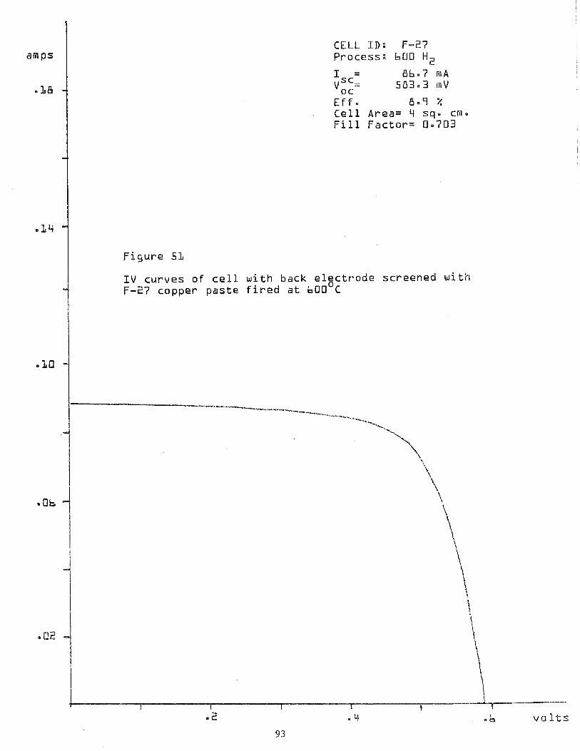
CELL I D : F-27 P r o c e s s : 600 H z
I = Bb-7 m A v::= 5 8 3 . 3 m V
E f f . 8.7 % C e l l A r e a = 4 sq. cm. F i l l F a c t o r = 0.703
F i g u r e 51
1 V . c u r v e s o f c e l l w i t h b a c k e l g c t r o d e s c r e e n e d w i t h F-27 c o p p e r p a s t e f i r e d a t 600 C
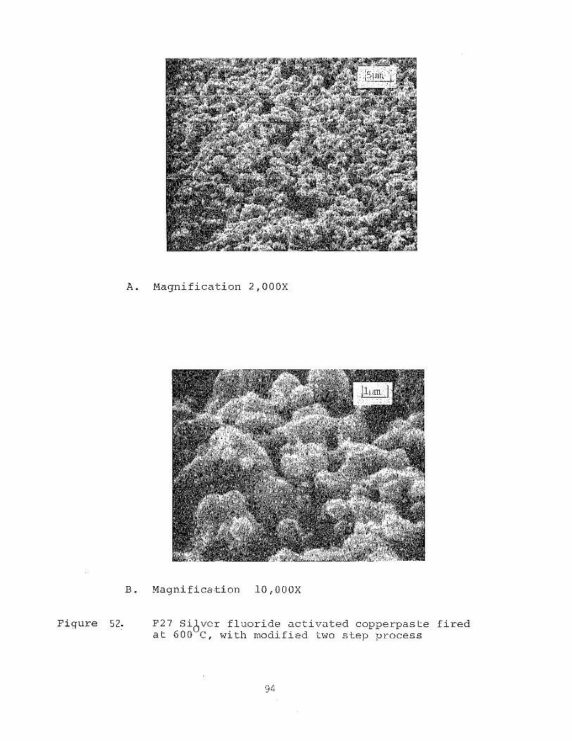
Figure
A . Magni f ica t ion 2,000X
Magni f ica t ion 10,000X
F27 S i ve r f l u o r i d e a c t i v a t e d copperpas te A a t 6 0 0 C , wi th modified two s t e p process
f i r
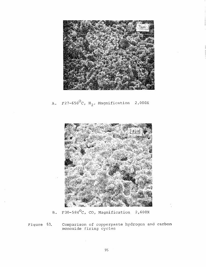
0 A. F27-650 C, H2, Magnification 2,000X
. ~ 3 0 - 5 8 4 ~ ~ , CO, Magnification 2,600X
Figure 53. Comparison of copperpaste hydrogen and carbon monoxide firing cycles
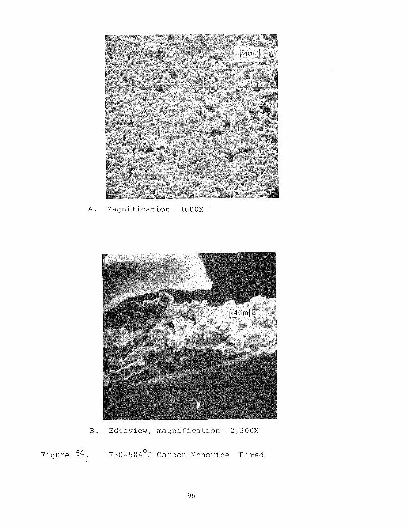
B . E d g e v i e w , m a g n i f i c a t i o n 2,300X
F i g u r e 5 4 . ~ 3 0 - 5 8 4 O C Ca rbon Monoxide F i r e d
o f i n t e r e s t . T h i s can be s e e n on F i g u r e 53 A and B, r e s p e c t -
i v e l y . A 1 though t h e m a g n i f i c a t i o n s a r e roughly comparable
and t h e hydrogen f i r e d sample was a t a h i g h e r t e m p e r a t u r e
(650°C v s 584°C) t h e degree o f s i n t e r i n g i n t h e carbon
monoxide f i r e d specim3n i s v a s t l y g r e a t e r . T h i s i s b e l i e v e d
t o be due t o t h e p r e v e n t i o n o f ox ide fo rmat ion e a r l y i n t h e
f i r i n g c y c l e wi th consequen t ly b e t t e r w e t t i n g ( a s d i s c u s s e d
i n S e c t i o n 9 . 3 ) .
F i g u r e 54 A and B show a more mic roscop ic view and an edge on
view, r e s p e c t i v e l y . The l O O O X micrograph a g a i n d e m o n s t r a t e s
t h e d r a m a t i c a l l y improved s i n t e r i n g . The c l e a v e d p o r t i o n o f
B shows t h e absence o f a s p i k e d e u t e c t i c phase b u t a p p e a r s t o
show good s u b s t r a t e w e t t i n g . The l a r g e amorphous-appearing
s t r u c t u r e above t h e micrograph i s a brushed-on c o a t i n g o f
g r a p h i t e t o p r e v e n t specimen c h a r g i n g . F i g u r e 55 shows
a n o t h e r SEM micrograph o f a r e g i o n o f t h e F30-CO p r i n t t h a t
was s c r a t c h e d w i t h a diamond s c r i b e . The rounded r e g i o n s
wi th and w i t h o u t t h e growth s t r i a t i o n s were s u b j e c t e d t o
energy d i s p e r s i v e x - ray a n a , l y s i s . The prominent l i n e s were
i d e n t i f i e d a s l e a d .
The problem o f hydrogen f i r i n g i n c o n j u n c t i o n w i t h e v i d e n c e
from t h e l i t e r a t u r e p r o v i d e s a r e a s o n a b l e b a s i s f o r hydrogen
s a t u r a t i o n o f d a n g l i n g bond e l e c t r o n s . T h i s d i s p l a c e s metal
atoms of e l e c t r o d e m a t e r i a l s . For t h i s r eason hydrogen i s a n
u n l i k e l y c a n d i d a t e f o r a r educ ing g a s f i r i n g ambient .
The ev idence o b t a i n e d from t h e carbon monoxide f i r i n g makes
i t appear w e l l s u i t e d t o t h e t a s k . However, p r e l i m i n a r y
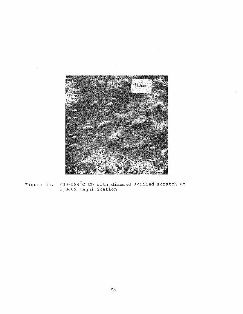
0 Figure 55. F30-584 C CO with diamond scribed scratch at 1,000X magnification
e x p e r i m e n t s w i t h f l u o r o c a r b o n p a s t e s f i r e d i n CO s t i l l show a
l a c k o f c o n s i s t e n t l y good a d h e s i o n . T h i s h a s l e d u s t o
c o n t i n u e d e x p e r i m e n t a t i o n w i t h s i l v e r f l u o r i d e a c t i v a t e d
i n k s .
Good e f f i c i e n c y and r e l a t i v e l y good a d h e s i o n h a v e been
o b t a i n e d f o r hydrogen f i r e d p a s t e s w i t h small ( < l w t % ) s i l v e r
f l u o r i d e a d d i t i v e s .
A s o l a r c e l l e x p e r i m e n t was c a r r i e d o u t w i t h c o p p e r p a s t e s
F l 9 and F20. Compos i t i ons are g i v e n i n T a b l e I X .
TABLE I X
COPPER PASTES F-19 A N D F-20
Material F l g w t % F20 w t %
V e h i c l e Copper Lead A1-Si E u t e c t i c S i l v e r F l u o r i d e Lead A c e t a t e F l u o r o c a r b o n
Copper p a s t e s were s c r e e n e d o n t o t h e b a c k s o f phosphorus
d i f f u s e d 2x2 cm s o l a r c e l l b l a n k s . S c r e e n e d w a f e r s were
d r i e d and s u b s e q u e n t l y f i r e d a t 615OC Peak Tempera tu re .
T i t a n i u m - p a l l a d i u m - s i l v e r c o n t a c t s were e v a p o r a t e d t h r o u g h a
mask o n t o t h e f r o n t o f t h e d e v i c e s . Two c o n t r o l c e l l s were
made o f t h e same m a t e r i a l w i t h Ti-Pd-Ag c o n t a c t s f r o n t a n d
b a c k , R e p r e s e n t a t i v e I V c u r v e s a r e shown i n F i g u r e s 56 a n d
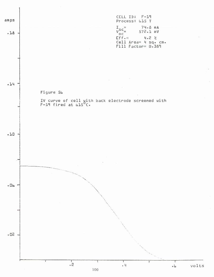
amps CELL ID: F-19 Process: bL5 T
I = 7q.8 m A v::= 572.1 m V
E f f - = q.2 % Cell Area= !! s q - cm- F i l l Factor= 0-389
Figure 56
I V curve of c e l l 8 i t h back e lec trode screened with F-17 f i r e d a t bL5 C -
-b v o l t s
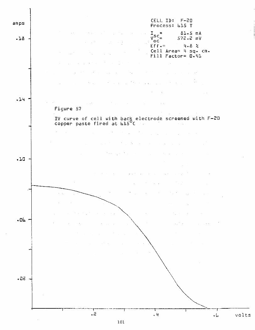
amps CELL ID: F-20 Process: b 1 5 T
I = 81.5 m A . L B v::= 572.2 m V
E f f e = 4-19 % C e l l Area= 4 sq. cm- F i l l F a c t o r = 0.41
.LLi
F i g u r e 57
I V curve o f c e l l w i t h back e l e c t r o d e screened w i t h F-20 copper p a s t e f i r e d a t bL5 C
* ob
.2 . b v o l t s
57. The c o n t r o l c e l l s gave normal IV c u r v e s w i t h A M 1
e f f i c i e n c i e s i n t h e 8% range ( w i t h o u t RR c o a t i n g ) .
The r e v e r s e S shaped c u r v e s a r e l i k e l y t o be due t o an
e l e c t r i c a l b a r r i e r i n s e r i e s wi th t h e ohmic c o n t a c t . T h i s
may be a consequence of a r e l a t i v e l y low f i r i n g t e m p e r a t u r e
(615OC), a l t h o u g h good c o n t a c t s have been made a t even Power
t e m p e r a t u r e s ( 5 5 0 ° C ) .
I t i s i n t e r e s t i n g t o n o t e t h a t s imilar c u r v e s were o b t a i n e d
a l t h o u g h t h e p a s t e s a r e , i n one c a s e , f l u o r o c a r b o n ( F l 9 ) and
i n t h e o t h e r , ( F 2 0 ) , s i l v e r f l u o r i d e a c t i v a t e d . The a p p l i -
c a t i o n o f t h e e v a p o r a t e d e l e c t r o d e s as w e l l a s t h e A M 1
s i m u l a t o r measurement and c u r v e t r a c i n g were done by t h e
S o l a r C e l l P r o c e s s i n g L a b o r a t o r y o f J e t P r o p u l s i o n
L a b o r a t o r y .
An e x p e r i m e n t was u n d e r t a k e n t o e x p l a i n t h e r e v e r s e S s h a p e d
c u r v e s o b t a i n e d from t h e I V t r a c e s o f s o l a r c e l l s d u r i n g t h i s
expe r imen t ( F i g u r e s 56 and 5 7 ) . An X-Y r e c o r d e r was u t i l i z e d
w i t h a s o l a r c e l l as shown i n F i g u r e 58 . The rough I V t r a c e s
r e s u l t e d from t h e c rude l o a d c i r c u i t u t i l i z i n g a s i n g l e 2 kR
v a r i a b l e r e s i s t o r . The i l l u m i n a t e d s o l a r c e l l w i th t h e
t r a n s i s t o r e m i t t e r s h o r t e d i s shown as c o n d i t i o n 1. The
t r a c e l a b e l e d 2 shows t h e s w i t c h open, p u t t i n g t h e germanium
e m i t t e r i n s e r i e s w i t h t h e s o l a r c e l l and y i e l d i n g a
f a c s i m i l e o f t h e r e v e r s e S shaped c u r v e .
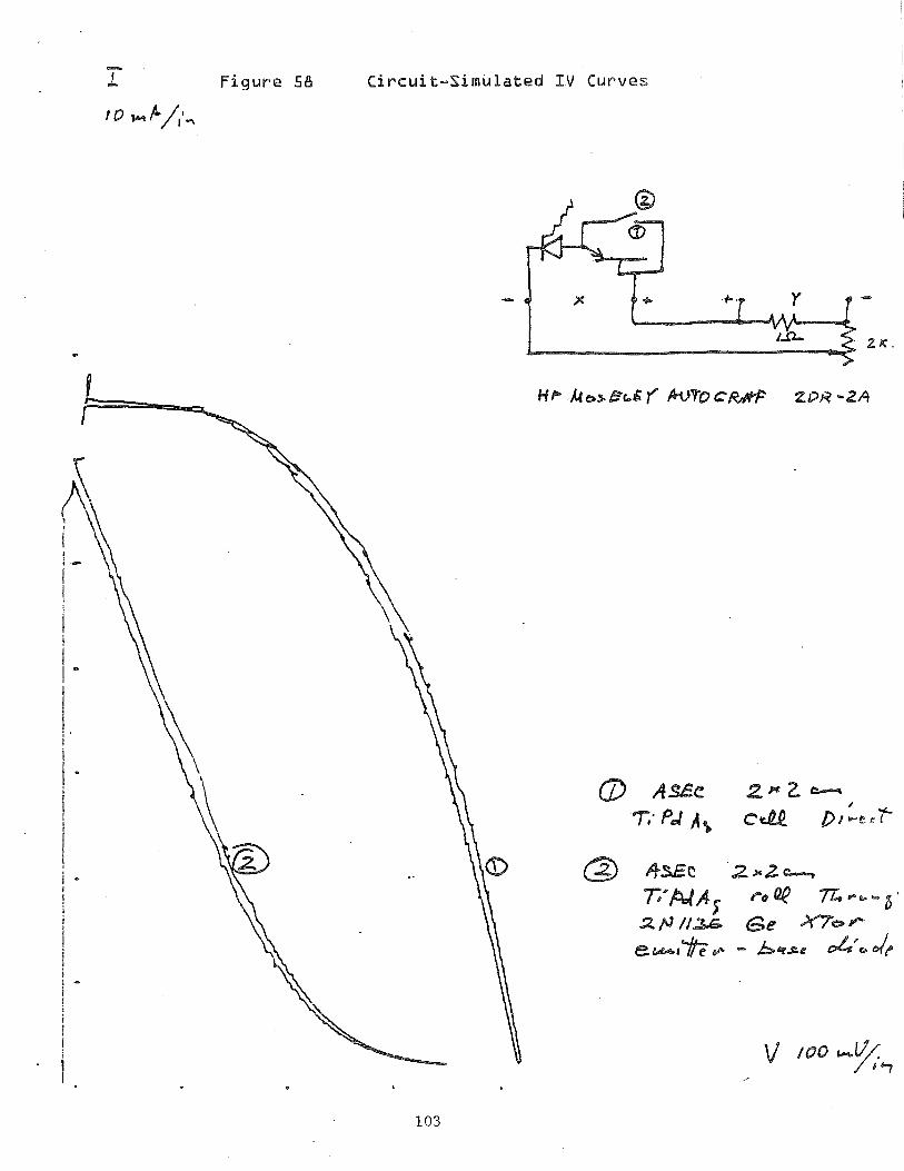
- L Figure 58 Circuit-Simulated I V Curves
f €3 b/,L,
10.0 COST ANALYSIS
While pastes manufactured to date do not satisfy all the
requirements with respect to adhesion, electrical properties
and resistance to environmental factors, a preliminary cost
study was undertaken.
The cost elements provided in this study should be looked
upon as constituting the upper limit in most cases. The
major constituent, copper metal powder, is presently obtained
from a high priced source in order to maintain close limits
on a variety of physical parameters. It is expected that
further experimentation and insight will allow the
utilization of a less expensive material, however, present
colculations are based upon the high copper price of $32/lb.
This material has not been made in volume production by the
manufacturer.
The sample pastes chosen for the cost analysis are F12
(silver fluoride) and F13 (fluorocarbon) compositions.
Material costs and component cost percentages are given in
Table X. The material costs are given in dollars per troy
ounce of paste.
The third and sixth column of numbers give the component cost
percentages of the total paste material costs. This nurnber
shows the cost drivers which are (in order of importance):
copper, solvent, resin and eutectic materials, with silver
fluoride being in 5th place.
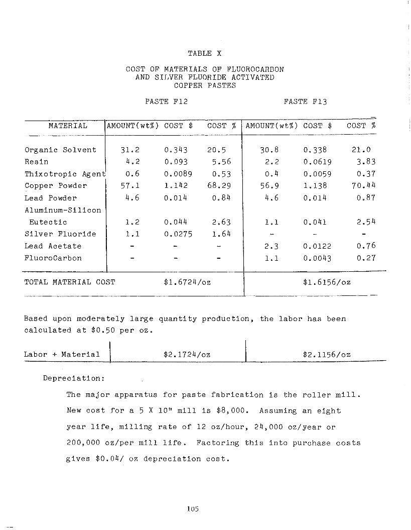
TABLE X
COST OF MATERIALS OF FLUOROCARBON AND SILVER FLUORIDE ACTIVATED
COPPER PASTES
PASTE F12 PASTE F13
Organ ic S o l v e n t
R e s i n
T h i x o t r o p i c Agent
Copper Powder
Lead Powder
Aluminum-Silicon
E u t e c t i c
S i l v e r F l u o r i d e
Lead A c e t a t e
F l u o r o c a r b o n
-
TOTAL MATERIAL COST $1.6724/0z $1.6156/0z
Based upon m o d e r a t e l y l a r g e q u a n t i t y p r o d u c t i o n , t h e l a b o r h a s been
c a l c u l a t e d a t $0.50 p e r o z .
AMOUNT(wt%) COST $ COST % MATERIAL
D e p r e c i a t i o n :
The m a j o r a p p a r a t u s f o r p a s t e f a b r i c a t i o n i s t h e r o l l e r m i l l .
N e w c o s t f o r a 5 X 10" m i l l i s $8,000. Assuming a n e i g h t
y e a r l i f e , m i l l i n g ra te o f 1 2 oz /hour , 24,000 o z / y e a r o r
200,000 o z / p e r m i l l l i f e . F a c t o r i n g t h i s i n t o p u r c h a s e c o s t s
g i v e s $0.04/ oz d e p r e c i a t i o n c o s t .
AMOUNT(wt%) COST $ COST %
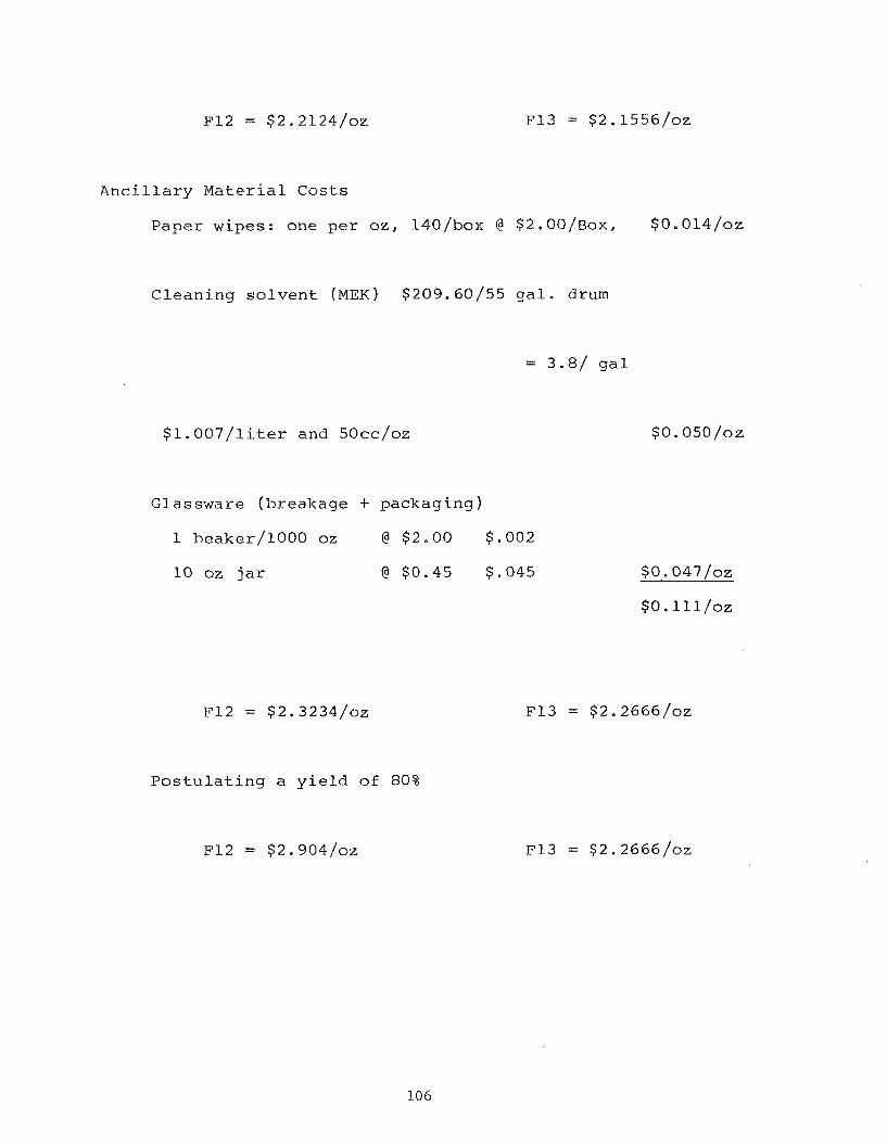
A n c i l l a r y M a t e r i a l C o s t s
P a p e r wipes : one p e r o z , 140/box @ $ ~ . O O / B O X , $0 .014/oz
C l e a n i n g s o l v e n t (MEK) $209.60/55 g a l . drum
= 3 . 8 / g a l
$ 1 . 0 0 7 / l i . t e r and 50cc /oz
G l a s s w a r e ( b r e a k a g e + p a c k a g i n g )
1 heake r /1000 oz @ $ 2 . 0 0 $.002
1 0 oz j a r @ $ 0 . 4 5 $.045
F12 = $2.3234/02
P o s t u l a t i n g a y i e l d of 80%
F12 = $2.904/oz
S O . 047 /oz
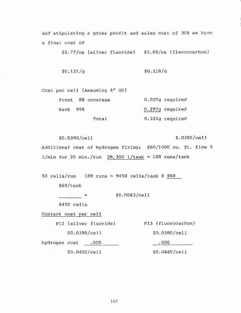
and stipulating a gross profit and sales cost of 30% we have
a final cost of
$3.77/oz (silver fluoride) $3.68/sz (fluoroearbonf
Cost per cell (~ssuming 4" OD)
Front 8% coverage
Back 95%
Total
0.025g required
0.2979 required
0.322g required
$0.0390/cell $. 0380/cell
Additional cost of hydrogen firing: $60/1000 cu. ft. flow 5
l/min for 30 min./run 28,300 l/tank = 189 runs/tank
50 cells/run 189 runs = 9450 cells/tank @ $60
- - $0.0063/cell
4450 cells
Contact cost per cell
F12 (silver fluoride)
hydrogen cost .006
$0.0450/cell
F13 ( fluorocarbon,)
$0.0380/cell
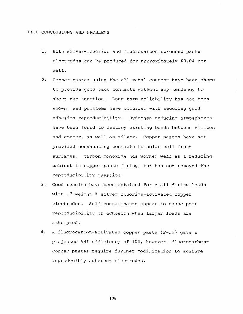
11.0 CONCLUSIONS AND PROBLEMS
1. Both silver-fluoride and fluorocarbon screened paste
electrodes can be produced for approximately $0.04 per
watt.
2. Copper pastes using the all metal concept have been shown
to provide good back contacts without any tendency to
short the junction. Long term reliability has not been
shown, and problems have occurred with securing good
adhesion reproducibility. Hydrogen reducing atmospheres
have been found to destroy existing bonds between silicon
and copper, as well as silver. Copper pastes have not
provided nonshunting contacts to solar cell front
surfaces. Carbon monoxide has worked well as a reducing
ambient in copper paste firing, but has not removed the
reproducibility question.
3. Good results have been obtained for small firing loads
with . 7 weight % silver fluoride-activated copper
electrodes. Self contaminants appear to cause poor
reproducibility of adhesion when larger loads are
attempted.
4. A fluorocarbon-activated copper paste (F-16) gave a
projected AM1 efficiency of lo%, however, fluorocarbon-
copper pastes require further modification to achieve
reproducibly adherent electrodes.
5. The effect of hydrogen upon adhesion has brought into
question the basic nature of the electrode bonding
mechanisms. Many observations support the hypothesis
that hydrogen, at firing temperatures, disrupts metal-
to-silicon bonds, replacing metal and causing separation
of electrodes.
12.0 RECOMMENDATIONS
A problem which must be solved is the lack of reproduci-
bility. This may be due in part to the variability in
certain raw materials such as silver fluoride, and to the
possibility of self contamination, possibly based upon the
number of wafers being fired.
A more complete understanding of the chemical processes,
outlined in Section 7, would be helpful in achieving better
control. This can be facilitated by further experiments with
thermogravimetric analysis (TGA) and differential thermal
analysis. (DTA)
The role of hydrogen on the silicon surface can only be
hypothesized at this point. Further experimentation and
analysis with the properties of silicon surfaces exposed to
various heat treatments in hydrogen ambients, would be not
only helpful to a narrow segment photovoltaic processing
technology, but to the whole semiconductor technology and
industry.
Another approach to the hydrogen problem is experimentation
with alternative reducing ambients, such as carbon monoxide
for example.
Finally the question whether copper electrodes can be used in
solar cell front surfaces must be further addressed.
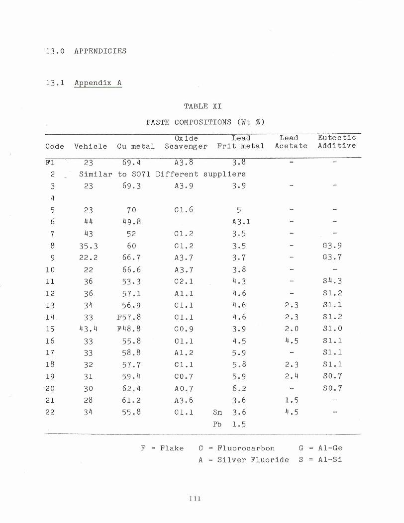
13.0 APPENDICIES
13.1 Appendix A
TABLE X I
PASTE COMPOSITIONS (Wt % )
Oxide Lead Lead E u t e c t i c Code V e h i c l e Cu metal Scavenger F r i t m e t a l A c e t a t e A d d i t i v e
FI 23 69.4 A3.8 3.8 - - 2 / S i m i l a r t o SO71 D i f f e r e n t s u p p l i e r s
3 23 69.3 A3.9 3.9
4
5 6
7 8
9
1 0
11
12
1 3
1 4
15 16
17
18
19
20
21
22
C1.2
C1.2
A397
A397
C2.1
A l . 1
C 1 . l
C 1 . l
co. 9
C 1 . l
A1.2
C 1 . l
C0.7
~ 0 . 7
A3.6
C 1 . l
s4.3 S1.2
S 1 . l
S1.2
S1.0
S 1 . l
S1.1
S 1 . l
SO. 7
SO. 7
F = F l a k e C = F l u o r o c a r b o n G = A 1 - G e
A = S i l v e r F l u o r i d e S = A 1 - S i
1 3 . 2 Appendix B
P a p e r p r e s e n t e d a t the 4 t h E.C. P h o t o v o l t a i c Ene rgy
C o n f e r e n c e , S t r e s a , I t a l y (May, 1 9 8 2 )
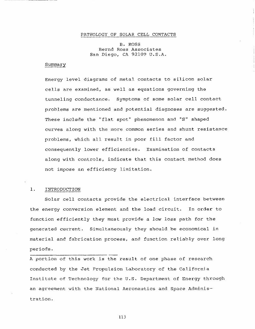
PATHOLOGY OF SOLAR CELL CONTACTS
B. ROSS Bernd Ross Associates
San Diego, CA 92109 U.S.A.
Sumrnarv
Energy level diagrams of metal contacts to silicon solar
cells are examined, as well as equations governing the
tunneling conductance. Symptoms of some solar cell contact
problems are mentioned and potential diagnoses are suggested.
These include the "flat spot" phenomenon and "S" shaped
curves along with the more common series and shunt resistance
problems, which all result in poor fill factor and
consequently lower efficiencies. Examination of contacts
along with controls, indicate that this contact method does
not impose an efficiency limitation.
1. INTRODUCTION
Solar cell contacts provide the electrical interface between
the energy conversion element and the load circuit. In order to
function efficiently they must provide a low loss path for the
generated current. Simultaneously they should be economical in
material and fabrication process, and function reliably over long
periods. -
A portion of this work is the result of one phase of research
conducted by the Jet Propulsion Laboratory of the California
Institute of Technology for the U.S. Department of Energy through
an agreement with the National Aeronautics and Space Adminis-
tration.
Several techniques are available to apply solar cell
1 2 3 contacts, including plating, alloying, vacuum evaporation, and
thick film screening.4". Despite this variety the final electr-
ical configuration is relatively simple, and is illustrated below.
2. FRONT CONTAC'I?
The front contact of modern solar cells is applied to nearly
degenerate n type semiconductor surfaces with impurity concent-
rations from 10'' atoms to lo2' atoms with phosporus being the
donor conventionally in use. The high surface concentration
allows better front contacts since the electron tunneling
probability is a function of the carrier concentration on both
sides of the interface. When a metal coats the surface of a semi--
conductor, the depletion width within the semiconductor shrinks as
a function of carrier concentration, enhancing the tunneling
probability. This iinproves carrier flow through the barrier
constituted by the contact potential between contact metal and
semiconductor surface.
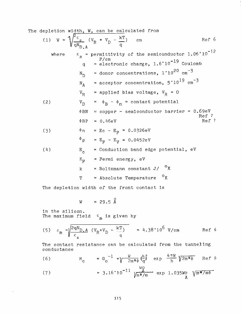
The d e p l e t i o n width , W , can be c a l c u l a t e d from C,
Ref 6
-12 where E m = p e r m i t t i v i t y o f t h e semiconductor 1 .06"10
D F/cm
q = e l e c t r o n i c cha rge , 1 . 6 ' 1 0 - ~ ~ Coulomb
N~ = donor c o n c e n t r a t i o n s , 1 * 1 O 2 O cm-3
N~ = a c c e p t o r c o n c e n t r a t i o n , 5 ' 1 0 ~ ~ cm-3
v~ = a p p l i e d b i a s v o l t a g e , VR = 0
v~ = @ B - @ n = c o n t a c t p o t e n t i a l
@ B N = copper - semiconductor b a r r i e r = 0.69eV Ref 7
@BP = 0.46eV Ref 7
@ n = Ec - EF = 0.0326eV
m p = E F - EV = 0.0452eV
Ec = Conduction band edge p o t e n t i a l , eV
E~ = Fermi energy , eV
k = Boltzrnann c o n s t a n t J/ O K
T 0 = Absolute Temperature K
The d e p l e t i o n wid th o f t h e f r o n t c o n t a c t i s
i n t h e s i l i c o n . The maximum f i e l d Em i s g i v e n by
Ref 6
The c o n t a c t r e s i s t a n c e can be c a l c u l a t e d from t h e t u n n e l i n g conductance
h 2 4nW -1 Ref 8 = G o Rc
= 3.16"lO -11 exp 1.035Wo A
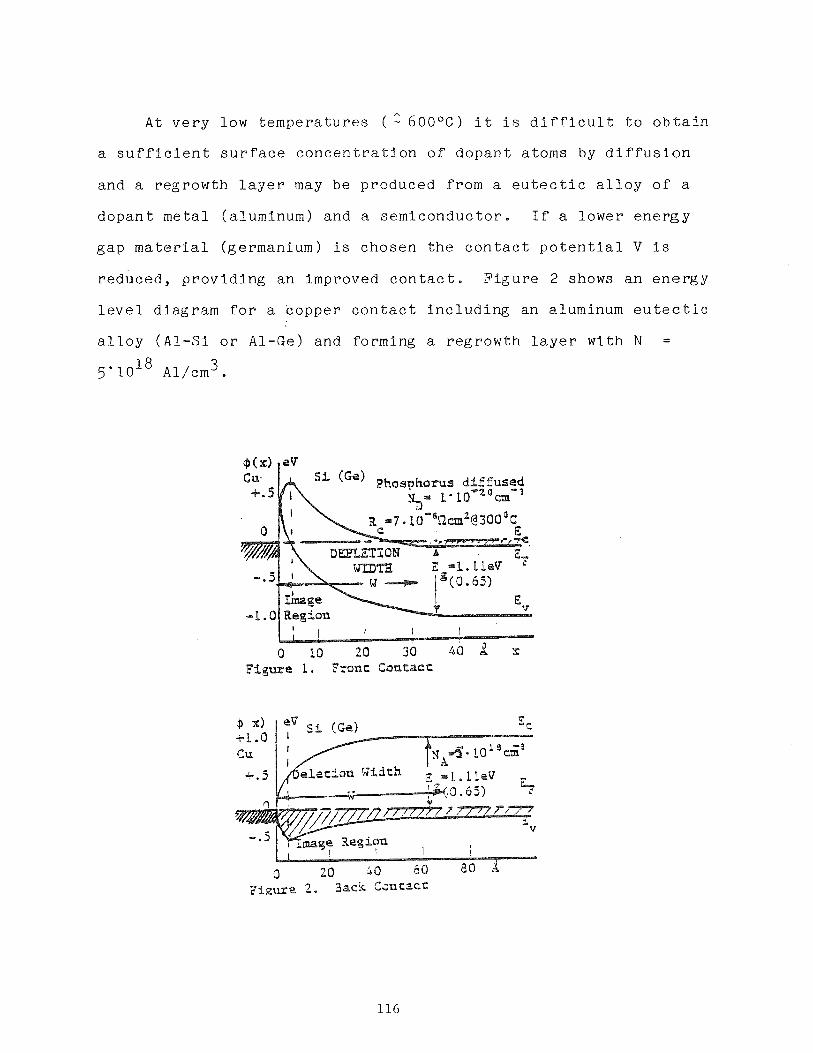
A
A t v e r y low t e m p e r a t u r e s ( - 6 0 0 ° c ) i t i s d i f f i c u l t t o o b t a i n
a s u f f i c i e n t s u r f a c e c o n c e n t r a t i o n o f d o p a n t a toms by d i f f u s i o n
and a r eg rowth l a y e r may be produced from a e u t e c t i c a l l o y o f a
d o p a n t m e t a l (a luminum) and a s e m i c o n d u c t o r . If a lower e n e r g y
g a p m a t e r i a l (germanium) i s chosen t h e c o n t a c t p o t e n t i a l V i s
r educed , p r o v i d i n g an improved c o n t a c t . F i g u r e 2 shows a n e n e r g y
l e v e l d iagram f o r a c o p p e r c o n t a c t i n c l u d i n g an aluminum e u t e c t i c
a l l o y (A l -S i o r A1-Ge) and forming a r eg rowth l a y e r w i th N =
3 5 . 1 0 ' ~ Al/crn .
C u +.5 hsi 1 ('@) P h o s p h o r ~ s d l 2 fused
&," 1e10r20cm-3
I lfnane -1.0 Region
Figure 1. Fronc Goatacc
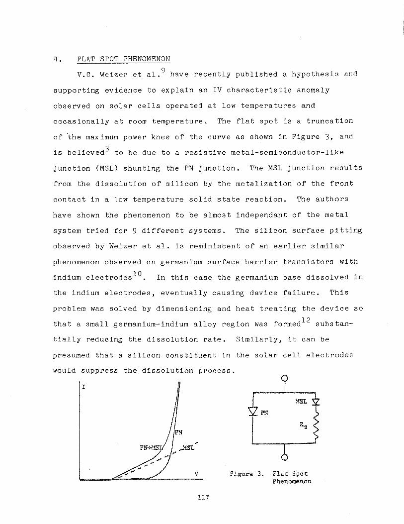
4 . FLAT SPOT PHENOMENON
V.G. Weizer e t a 1 .' have r e c e n t l y p u b l i s h e d a h y p o t h e s i s and
s u p p o r t i n g e v i d e n c e t o e x p l a i n a n I V c h a r a c t e r i s t i c anomaly
obse rved on s o l a r c e l l s o p e r a t e d a t low t e m p e r a t u r e s and
o c c a s i o n a l l y a t room t e m p e r a t u r e . The f l a t s p o t i s a t r u n c a t i o n
o f ' the maximum power knee o f t h e c u r v e a s shown i n F i g u r e 3, and
i s b e l i e v e d 3 t o be due t o a r e s i s t i v e m e t a l - s e m i c o n d u c t o r - l i k e
j u n c t i o n (MSL) s h u n t i n g t h e PN j u n c t i o n . The MSL j u n c t i o n r e s u l t s
from t h e d i s s o l u t i o n o f s i l i c o n by t h e m e t a l i z a t i o n o f t h e f r o n t
c o n t a c t i n a low t e m p e r a t u r e s o l i d s t a t e r e a c t i o n . The a u t h o r s
have shown t h e phenomenon t o be a l m o s t i n d e p e n d a n t o f t h e m e t a l
sy s t em t r i e d f o r 9 d i f f e r e n t s y s t e m s . The s i l i c o n s u r f a c e p i t t i n g
obse rved by Weizer e t a l . i s r e m i n i s c e n t o f an e a r l i e r similar
phenomenon obse rved on germanium s u r f a c e b a r r i e r t r a n s i s t o r s w i t h
ind ium e l e c t r o d e s l O . I n t h i s c a s e t h e germanium base d i s s o l v e d i n
t h e ind ium e l e c t r o d e s , e v e n t u a l l y c a u s i n g d e v i c e f a i l u r e . T h i s
p rob lem was s o l v e d by d imens ion ing and h e a t t r e a t i n g t h e d e v i c e s o
t h a t a s m a l l germanium-indium a l l o y r e g i o n was formed1* s u b s t a n -
t i a l l y r educ ing t h e d i s s o l u t i o n r a t e . S i m i l a r l y , i t c a n be
presumed t h a t a s i l i c o n c o n s t i t u e n t i n t h e s o l a r c e l l e l e c t r o d e s
would s u p p r e s s t h e d i s s o l u t i o n p r o c e s s .
Sigure 3. F l a t S p o t E" henomenon
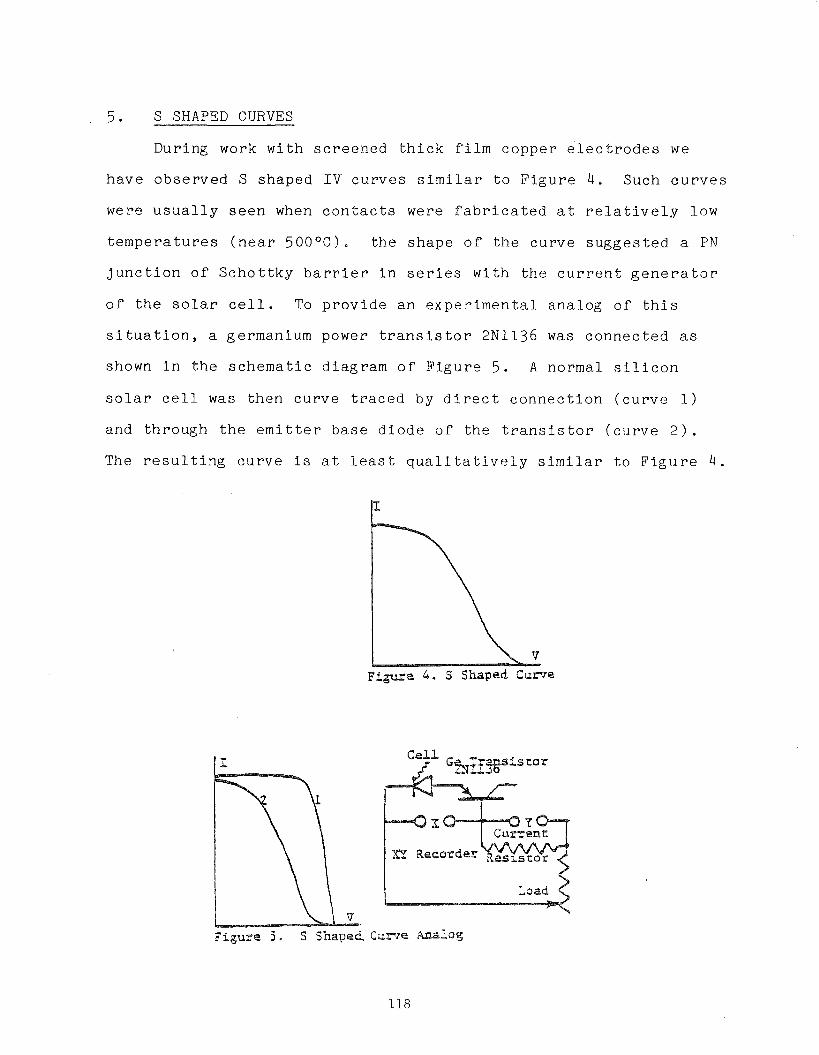
5 . S SHAPED CURVES
During work w i t h s c r e e n e d t h i c k f i l m coppe r e l e c t r o d e s we
have obse rved S shaped I V c u r v e s s i m i l a r t o F i g u r e 4, Such c u r v e s
were u s u a l l y s e e n when c o n t a c t s were f a b r i c a t e d a t r e l a t i v e l y low
t e m p e r a t u r e s ( n e a r 5 0 0 ° C ) . t h e shape o f t h e cu rve s u g g e s t e d a PN
j u n c t i o n o f S c h o t t k y b a r r i e r i n s e r i e s w i t h t h e c u r r e n t g e n e r a t o r
o f t h e s o l a r c e l l . To p r o v i d e a n e x p e r i m e n t a l ana log o f t h i s
s i t u a t i o n , a germanium power t r a n s i s t o r 2N1136 was connec t ed a s
shown i n t h e s c h e m a t i c d i ag ram o f F i g u r e 5 . A normal s i l i c o n
s o l a r c e l l was t h e n cu rve t r a c e d b y d i r e c t c o n n e c t i o n ( c u r v e 1 )
and th rough t h e e m i t t e r ba se d i o d e o f t h e t r a n s i s t o r ( c u r v e 2 ) .
The r e s u l t i n g c u r v e i s a t l e a s t q u a l i t a t i v e l y s i m i l a r t o F i g u r e 4 .
Figure 4 . S Shaped C u r v e
P i g u r e 3 . S Shaped
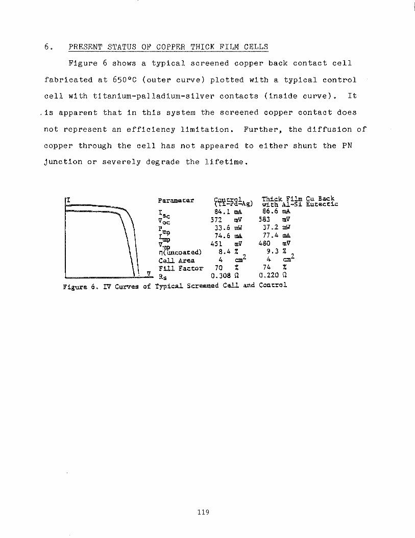
6 . PRESENT STATUS OF COPPER THICK FILM CELLS
F i g u r e 6 shows a t y p i c a l s c r e e n e d copper back c o n t a c t c e l l
f a b r i c a t e d a t 650°C ( o u t e r c u r v e ) p l o t t e d wi th a t y p i c a l c o n t r o l
c e l l w i t h t i t a n i u m - p a l l a d i u m - s i l v e r c o n t a c t s ( i n s i d e c u r v e ) . I t
. i s a p p a r e n t t h a t i n t h i s sys t em t h e s c r e e n e d copper c o n t a c t d o e s
n o t r e p r e s e n t an e f f i c i e n c y l i m i t a t i o n . F u r t h e r , t h e d i f f u s i o n o f
copper th rough t h e c e l l h a s n o t appea red t o e i t h e r s h u n t t h e PN
j u n c t i o n o r s e v e r e l y d e g r a d e t h e L i f e t i m e .
Figure 6 . IT Cumes of
c u &ea 4 cmL F l l l Factor 70 X 9 s 0.308 Q
Tgpical Screened C a l l and
Thick Film with a - S i 86 .6 mA
583 mV 37.2 stJ 77.4 ma
480 mV 9 . 3 X
2 4 cm 7 4 X
0.220 n
Cu Back Eu+eccic
where h = P l a n c k ' s c o n s t a n t
(mu/,), = 0.1905 t h e e f f e c t i v e e l e c t r o n i c mass i n t h e (100) d i r e c t i o n
( 8 ) ( m * / m l h = 0.16 t h e e f f e c t i v e h o l e mass i n t h e < l o o > d i r e c t i o n
E = Energy g a p o f s i l i c o n = l . l l e V €5
Germanium = 0.65eV
The c a l c u l a t e d f r o n t c o n t a c t t u n n e l i n g r e s i s t a n c e i s
= 1 . 6 9 . 1 0 ' ~ Rcm 2 R c
S i n c e t h e b a r r i e r v o l t a g e v a l u e s v a r y among w o r k e r s , and t h e i r
magn i tude a f f e c t s t h e a rgument o f the e x p o n e n t i n e q u a t i o n 6 and
7 , t h e c a l c u l a t e d c o n t a c t r e s i s t a n c e i s s u b j e c t t o wide v a r i a t i o n .
The e n e r g y band r e l a t i o n s h i p s f o r a c o p p e r c o n t a c t on a s i l i c o n
f r o n t s u r f a c e doped w i t h 1 . 1 0 ~ ' phosphorous a toms a r e shown i n
F i g u r e 1.
3. BACK CONTACT
When t h e s e m i c o n d u c t o r s u r f a c e h a s a h i g h e r r e s i s t i v i t y , a s
on t h e back c o n t a c t , i t i s n e c e s s a r y t o dope t h e s u r f a c e o f t h e
s e m i c o n d u c t o r u n d e r t h e e l e c t r o d e m e t a l . I n c a s e o f h i g h f i r i n g
t e m p e r a t u r e s ( -800°C) a n e l e m e n t a l d o n o r i m p u r i t y may b e i n c l u d e d
i n t h e m e t a l t o d i f f u s e i n t o t h e s e m i c o n d u c t o r d u r i n g t h e f i r i n g
s t e p . S i n c e o n l y t h e s u r f a c e n e e d s t o be doped, t h e d o n o r a t o m
must become a s u b s t i t u t i o n a l . i m p u r i t y i n t h e s i l i c o n l a t t i c e
w i t h i n a few l a t t i c e s p a c e s o f t h e s u r f a c e . A b r i e f f i r i n g p e r i o d
w i l l u s u a l l y s u f f i c e .
7 . CONCLUSION
We have p r e s e n t e d two c a s e s o f s e v e r e c o n t a c t problems s e e n
i n s o l a r c e l l s . While t h i s by no means e x h a u s t s t h e c a t a l o g o f
c o n t a c t ma lad ies , t h e examples were though t t o be o f i n t e r e s t .
Enegry l e v e l d iagrams f o r normal s o l a r c e l l c o n t a c t s were a l s o
r e p o r t e d .
The a u t h o r wishes t o e x p r e s s h i s g r a t i t u d e t o D r . I .
Weinberg, NASA Lewis Research Cen te r f o r p e r m i s s i o n t o r eproduce
F i g u r e 3 .
REFERENCES
P. Rappapor t , RCA Rev. 20, p.373 ( S e p t 1959) S . Matlow, US P a t e n t #2, 984, 775 (5-1961) P.A. I l e s , Conf. Rec. on IEEE P h o t o v o l t . Spec . Conf. , p . 1
(lqay 1972) E.L. Ralph, P roc . 1 1 t h IEEE P h o t o v o l t Spec . Conf. , p.315,
(1975) B . Ross and D.B. B i c k l e r , P roc . 3 rd E . C . P h o t o v o l t , S o l a r
Energy Conf. p.674, Cannes, F rance ( 0 c t . 1980) M.P. L e p s e l t e r and J.M. Andrews i n "Ohmic C o n t a c t s t o Semi-
c o n d u c t o r s ~ Ed.B. Schwar tz , Elec t rochem. Soc p.159, N e w York (1969)
E .H. Rhoder ick , "Metal Semiconductor C o n t a c t s , Claredon P r e s s , p .59, Oxford (1978)
J . G . Simmons, J o u r . Appl. Phys. p.34, 1793, ( June 1973) V.G. Weizer and J . D . Broder , P roc . 1 5 t h I E E E P h o t o v o l t .
Spec . Conf. , p.235, (May 1981) J . W . T i l e y and C . G . Thornton, Proc.IRE, 41,1706 ( ~ e c 1953) J . Roschen and C . G . Thornton, Jour .Appl .Phys. 29,923 ( J u n e
1958) A . D . Ri t tmann, G . C . Messenger, R.W.Williams and E.Zimmerman,
IRE Trans . on E1.Dev 5,49 (Apr 1958)
14.0 REFERENCES
B . Ross, P roceed ings o f t h e 1 4 t h IEEE P h o t o v o l t a i c S p e c i a l i s t s Confe rence , San Diego, C A p . 787
B . Ross, P roceed ings o f t h e 1 4 IEEE P h o t o v o l t a i c S p e c i a l i s t s Confe rence , San Diego, C A p . 1406
B . Ross, E x t e n s i o n F i n a l Repor t t f P r o d u c t i o n P r o c e s s and Equipment Development" DOE/JPL 955164 - 79/4 p . 72 (Dec. 1979)
B . Ross, Q u a r t e r l y R e p o r t #3 "Development o f an All-Metal Thick F i l m Cost E f f e c t i v e M e t a l i z a t i o n System f o r S o l a r C e l l s " DOE/JPL 955688 - 80/7, p . 18 ( S e p t . 1981)
Loc c i t , Re f . 3, p.10
I b i d , p . 72
M.P. L e p s e l t e r and J.M. Andrews i n Ohmic " C o n t a c t s t o Semiconductors" , B . Schwar tz , Ed., E lec t rochem. Soc . p . 159 New York (1969)
E.H. Roder i ck , "Metal Semiconductor C o n t a c t s t t , Clarendon P r e s s , p . 59, Oxford (1978)
J . G . Simmons, J o u r . Appl. Phys. , 34 1793 (Jun 1973)
Handbook o f Chemis t ry and P h y s i c s , 5 7 t h e d i t i o n , CRC P r e s s , C leve land , OH, (1976-77)
F.T.Wal1, Itchemical Thermodynamics", W.H. Freeman, San F r a n c i s c o , C A , p . 47 e t s e q . (1958)
B . Ross, and D . Mentley Q u a r t e r l y Repor t # 1 "Development o f Economical Improved Thick F i lm S o l a r C e l l C o n t a c t s f t , DOE/JPL 955-164-78/4 p . 9,10 ( J a n . 1979)
B . H . Mahan, t fE lemen ta ry Chemical Thermodynamics~ , W . A . Benjamin, New York, N . Y . , p. 27-36 (1963)
N .I. Sax , f tDangerous P r o p e r t i e s o f I n d u s t r i a l M a t e r i a l s t f , Van Nost rand-Reinhold , New York, p . 972. ( 1 9 7 9 )
L . B r e t h e r i c k , "Handbook o f R e a c t i v e Chemical H a z a r d s f 1 , B u t t e r w o r t h s , London, p . 197 . (1979)
A . S t o c k , "Hydr ides o f Boron and S i l i c o n f ' , C o r n e l l Univ, Press, I t h i c a , N , P , , (1933)
1 7 . T . M o e l l e r , " I n o r g a n i c C h e m i s t r y n , John Wiley , New York, (1952)
18 . B e Ross , Q u a r t e r l y R e p o r t No. 1 "Development o f a n A l l - Me ta l Thick F i lm Cos t E f f e c t i v e M e t a l i z a t i o n Sys tem f o r S o l a r C e l l s 1 I , DOE/JPL 955688-80/4, August 1980