Embed Size (px)
Citation preview

University of South Carolina University of South Carolina
Scholar Commons Scholar Commons
Theses and Dissertations
Summer 2019
Development of an Automated Fiber Placement Process for the Development of an Automated Fiber Placement Process for the
Fabrication of Thermoplastic Composite Laminates Fabrication of Thermoplastic Composite Laminates
Anthony M. Sabido
Follow this and additional works at: https://scholarcommons.sc.edu/etd
Part of the Aerospace Engineering Commons
Recommended Citation Recommended Citation Sabido, A. M.(2019). Development of an Automated Fiber Placement Process for the Fabrication of Thermoplastic Composite Laminates. (Master's thesis). Retrieved from https://scholarcommons.sc.edu/etd/5332
This Open Access Thesis is brought to you by Scholar Commons. It has been accepted for inclusion in Theses and Dissertations by an authorized administrator of Scholar Commons. For more information, please contact [email protected].

DEVELOPMENT OF AN AUTOMATED FIBER PLACEMENT PROCESS FOR THE
FABRICATION OF THERMOPLASTIC COMPOSITE LAMINATES
by
Anthony M. Sabido
Bachelor of Science
Florida State University, 2012
Submitted in Partial Fulfillment of the Requirements
For the Degree of Master of Science in
Aerospace Engineering
College of Engineering and Computing
University of South Carolina
2019
Accepted by:
Michel Van Tooren, Director of Thesis
Ramy Harik, Reader
Cheryl L. Addy, Vice Provost and Dean of the Graduate School

ii
© Copyright by Anthony M. Sabido, 2019
All Rights Reserved.

iii
ACKNOWLEDGEMENTS
I would like to thank Andrew Eulberg, Michael Keifer, Burton Rhodes, Susan
Rogers, Rachael Rudd, and Tyler Strampp for all of their assistance and expertise. I could
not have asked for better Team Wombat members to have helped me along the way. I
would also like to thank my advisors Dr. Michel Van Tooren and Dr. Ramy Harik.
Without their support and assistance, I would not have finished my graduate career at the
University of South Carolina. Lastly, I would like to thank my parents Jorge and Marisol
Sabido. Their love and support have always aided me in tackling any challenges in my
path.

iv
ABSTRACT
An automated fiber placement process is desired for manufacturing variable-
stiffness thermoplastic composite laminates. By developing such a composite laminate, it
is possible to take advantage of the tunable performance increases that are achievable by
spatially steering individual tows. In addition, using a thermoplastic polymer as the
matrix material has many advantages: a high toughness, ability to employ thermoplastic
joining processes that do not require adhesives, long storage life, and lacks the need to be
refrigerated. This process was experimentally developed, where the effect of various
process parameters on the quality of the laminate were evaluated. An experimental AFP
head was developed in order to monitor and record the compaction pressure, heating
temperature, tool temperature, and tow tension in-situ. By comparing the resulting layups
to traditional processes, a quantitative assessment is made on the ability to automatically
place thermoplastic composite tows for the manufacturing of constant stiffness composite
laminates. Lastly, the feasibility of utilizing this process for the fabrication of variable
stiffness thermoplastic composites is assessed.

v
TABLE OF CONTENTS
ACKNOWLEDGEMENTS ............................................................................................... iii
ABSTRACT ....................................................................................................................... iv
LIST OF TABLES ........................................................................................................... viii
LIST OF FIGURES ............................................................................................................ x
LIST OF SYMBOLS ........................................................................................................ xii
LIST OF ABBREVIATIONS .......................................................................................... xiv
CHAPTER 1 INTRODUCTION ........................................................................................ 1
CHAPTER 2 LITERATURE REVIEW ............................................................................. 4
2.1 EARLY DEVELOPMENTS ..................................................................... 4
2.2 MANUFACTURING CONSTRAINTS ................................................... 6
2.3 TOOL PATH DESIGN ........................................................................... 10
2.4 THERMOPLASTIC COMPOSITES ...................................................... 12
CHAPTER 3 RESEARCH OBJECTIVES ....................................................................... 15
3.1 MATERIAL SELECTION ..................................................................... 16
3.2 AUTOMATED FIBER PLACEMENT .................................................. 19
3.3 PROCESS EVALUATION..................................................................... 24

vi
CHAPTER 4 EXPERIMENTAL PROCEDURES ........................................................... 25
4.1 DESIGN OF EXPERIMENTS................................................................ 25
4.2 TENSILE TESTING ............................................................................... 36
4.3 DRYING OF CARBON/PEI TOWS ...................................................... 39
CHAPTER 5 PRELIMINARY EXPERIMENTAL SETUP ............................................ 41
5.1 OVERVIEW............................................................................................ 41
5.2 FIBER PLACEMENT HEAD ................................................................ 43
5.3 HEAT SOURCES ................................................................................... 45
5.4 FIBER TENSIONER .............................................................................. 47
5.5 HEATED TOOL ..................................................................................... 49
5.6 INTEGRATION WITH ARTICULATED ROBOT ARM ..................... 50
CHAPTER 6 RESULTS AND ANALYSIS..................................................................... 53
6.1 HEAT SOURCE COMPARISON .......................................................... 53
6.2 HEATING LIMITATIONS .................................................................... 58
6.3 COMPACTION PRESSURE .................................................................. 60
6.4 TOW TENSION ...................................................................................... 69
6.5 FEED RATE AND PLY NUMBER ....................................................... 69
6.6 LAMINATE MANUFACTURING CHALLENGES ............................. 71
6.7 FIBER STEERING ................................................................................. 74
CHAPTER 7 CONCLUSIONS ........................................................................................ 76

vii
CHAPTER 8 FUTURE WORK AND RECOMMENDATIONS .................................... 79
REFERENCES ................................................................................................................. 82
viii
LIST OF TABLES
Table 3.1 Typical Mechanical Properties for Cetex TC1000 (PEI), AS4,
145gsm, 32% RC ...............................................................................................................16
Table 3.2 Typical Material Properties for ULTEM™ Resin 1000 ....................................16
Table 3.3 Typical Material Properties for HexTow® AS4 6K Carbon Fiber ...................17
Table 3.4 Process Variables ...............................................................................................20
Table 3.5 Experiment Descriptions....................................................................................21
Table 4.1 Control Factors for Experiment 1 ......................................................................26
Table 4.2 Full Factorial Design for Experiment 1 .............................................................27
Table 4.3 Baseline Process Parameters for Experiment 2 .................................................28
Table 4.4 Control Factors for Experiment 2 ......................................................................29
Table 4.5 Orthogonal Array L9(34) for Experiment 2 .......................................................29
Table 4.6 Control Factors for Experiment 3 ......................................................................30
Table 4.7 Orthogonal Array L9(33) for Experiment 3 ........................................................31
Table 4.8 Control Factors for Experiment 4 ......................................................................32
Table 4.9 Control Factors for Experiment 5a (n = 3) ........................................................33
Table 4.10 Control Factors for Experiment 5b (n = 5) ......................................................33
Table 4.11 Control Factors for Experiment 5c (n = 7) ......................................................34
Table 4.12 Full Factorial Design for Experiment 5 ...........................................................34
Table 6.1 Material Temperatures Reached for h1 = 10 mm and h2 = 15 mm ....................53

ix
Table 6.2 Compaction pressure at each of the rollers (MPa) .............................................60
Table 6.3 Optimum Compaction Force vs. Number of Rollers .........................................61
Table 6.4 SLS Test Results for Experiment 4....................................................................67
Table 6.5 SLS Test Results for Control Specimens ...........................................................67
Table 6.6 Results for Experiment 5 ...................................................................................69
x
LIST OF FIGURES
Figure 1.1 Schematic of an ATL head (left) [1] and an AFP head (right) [2] .....................4
Figure 3.1 Experimental AFP Machine .............................................................................19
Figure 4.1 Feasible roller speeds for each layer during a 20-ply lay-up process with a
preheat temperature of 150 °C [3]. ....................................................................................35
Figure 4.2 Single Lap Shear Specimen with [0/0] Orientation ..........................................36
Figure 4.3 Control Specimens............................................................................................38
Figure 5.1 AFP Design Flow Chart ...................................................................................41
Figure 5.2 AFP Head with 4 Roller Setup .........................................................................42
Figure 5.3 AFP Head Cross-Section with Dimensions ......................................................43
Figure 5.4 Compaction Force vs. Roller Displacement .....................................................44
Figure 5.5 303D Hot Air Rework Station and Modified Heater Tip .................................45
Figure 5.6 T835 Solder Station ..........................................................................................46
Figure 5.7 Repositionable Spool with Drag Braking System ............................................47
Figure 5.8 Mechanical Tensioner with Fitted Force Gage ................................................48
Figure 5.9 Heated Tool and PID Controller Setup ............................................................49
Figure 5.10 EtherCAT Fieldbus System and Power Supply..............................................50
Figure 6.1 Average Material Temperature vs. HA Heater Temperature Setting ...............53
Figure 6.2 Material temperature as a function of time for h = 10mm ...............................54
Figure 6.3 IR heating over time with h = 5 mm, Tt = 150 °C ...........................................56

xi
Figure 6.4 Secondary and Primary Heater Positioning ......................................................58
Figure 6.5 Normal Stress for Primary Roller vs. Compaction Force (Nr = 4) ..................62
Figure 6.6 Normal Stress for Secondary Rollers vs. Compaction Force (Nr = 4) ............63
Figure 6.7 Shear Stress Distributions for Various Compaction Forces .............................64
Figure 6.8 Contact Width and Normal Stress vs. Roller Diameter ....................................65
Figure 6.9 Layup on 3 layers (n = 3) at f = 3 mm/s (left) and f = 2.5 mm/s (right) ...........69
Figure 6.10 In-situ consolidation challenges during the layup of the 3rd layer..................72
Figure 6.11 Fiber steering trials at a radius of 200 mm .....................................................74
Figure 8.1 Second prototype for a thermoplastic AFP machine ........................................79

xii
LIST OF SYMBOLS
H Heat Source being used for primary heating of the tow being placed.
h Distance of the heat source to the tool surface.
Tt Temperature of the tool being consolidated on by the automated fiber placement
head.
Th Temperature setting of the primary heater.
TAFP Temperature setting of the secondary heater used to increase the overall
temperature of the compaction roller and heated zone.
T Temperature reached by the consolidated material being heated.
Tavg Average temperature reached by the consolidated material being heated.
Tmax Maximum temperature reached by the consolidated material being heated.
tss Time until a steady state temperature is reached by the consolidated material
being heated.
f Feed rate reached by the tool, equivalent to the roller speed for robot mounted
automated fiber placement heads.
Ft Tow tension set by the unidirectional drag braking system on the spool.
Fc Compaction force caused by the compression of the automated fiber placement
head by the robot mounted tool.
Nr Total number of rollers used, consisting of 1 primary compaction roller and
several secondary rollers.
n Number of layers that have been consolidated on the tool.
L Length of overlap by 2 tows where they will be bonded together.
t Thickness of the tow being consolidated.

xiii
Fty Tensile strength of the tow.
τ Average shear strength
b The half width of the contact area between a cylindrical roller and a surface.
Kb A dependent variable used in Hertzian Contact Theory for the analysis of two
cylindrical rollers in contact with parallel axis.
ν Poisson’s ratio .
E Elastic modulus.
d Diameter of the cylinder(s) used in the Hertzian contact stress formulations.
xiv
LIST OF ABBREVIATIONS
AFP ....................................................................................... Automated Fiber Placement
AFS .......................................................................................... Automated Fiber Steering
ATL ..............................................................................................Automated Tape Layup
CA ...................................................................................................... Cellular Automata
DAO ............................................................................ Domain of Admissible Orientation
DOE .............................................................................................. Design of Experiments
FW ...................................................................................................... Filament Winding
HA ....................................................................................................................... Hot Air
IR ....................................................................................................................... Infrared
LP .............................................................................................. Lamination Parameters
NOL ....................................................................................... Naval Ordnance Laboratory
PEEK ..................................................................................................Polyetheretherketone
PEI ........................................................................................................... Polyetherimide
PEKK ............................................................................................... Polyetherketoneketone
PPS ............................................................................................... Polyphenylene Sulfide
VSC ................................................................................... Variable Stiffness Composites

1
CHAPTER 1 INTRODUCTION
While Hyer and Charette have explored the optimization of fiber directions
throughout the domain of a VSC as early as 1987 [4], research on manufacturing
processes for such a composite laminate is a comparatively young area of study. In the
context of this paper, composite materials consist of a fibrous load bearing material
embedded in a resin matrix. By developing constituent materials for a composite, it is
possible to design a material that has a resultant set of properties tailored for a specific
structural purpose. Early research focused on improving the constituent materials by
developing high stiffness fibers, such as carbon/graphite, and high performance polymer
resins. Laminate design typically consists of determining the optimum materials,
constituent volume fraction, and ply stacking sequence where the resulting properties are
anisotropic. By orienting the fibers spatially within each ply, we expand and optimize the
laminate design space. The fiber paths in VSC can be tailored to maximize one or several
objective functions, such as minimum compliance or maximum strength. This is a
challenging concept to implement due to computing, monetary, and manufacturing
constraints. By allowing the fiber direction and volume fractions to be treated as design
variables, the computational requirements to optimize the laminate design increase
substantially. In addition, manufacturing a laminate where the fibers are tailored is
extremely labor intensive. The equipment needed to design and fabricate these composite

2
materials increase the overall costs associated with implementing VSC into various
industries.
The use of thermoplastic polymers as a matrix material in VSC is essentially
nonexistent. In the aerospace industry, thermoset polymers are much more prevalent than
expensive thermoplastics. Thermoplastics (PPS, PEI, PEEK, PEKK, etc.) have several
characteristics that make them desirable for use in the aerospace composites. Due to the
cross-linking that occurs in curing thermosets, thermoplastic composites generally exhibit
greater impact resistance and damage tolerance. There is also a benefit in the handling
and storage of thermoplastics, when compared to thermosets. Thermosets, for example,
require storage under refrigeration and have a much shorter shelf life. Comparatively,
thermoplastics have a near infinite shelf life and do not require refrigeration.
Thermoplastics do absorb moisture during storage, however, negatively affecting the
material’s performance. Sharp, Holmes, and Woodall showed the moisture absorption for
AS4/APC-2 (Carbon/PEEK) specimens and identified a saturation of 0.20% after 130
days [5]. It is therefore often necessary to include an additional prep-processing step of
using a drying unit to remove the moisture. While thermoplastic composites being
manufactured using automated fiber placement certainly isn’t new, the introduction of
fiber steering introduces several challenges that have yet to be thoroughly addressed.
In order to achieve the goal of fiber steering thermoplastic composites, this research
aims to develop an AFP process for manufacturing thermoplastic composites and
determine the viability of steering thermoplastic composite tows. In order to accomplish
this, many of the challenges of using a thermoplastic composite material must be
addressed by developing a unique experimental tool. One of the main challenges includes

3
the relatively high stiffness of the tows (when compared to a thermosetting composite
tow). This makes steering quite difficult without the creation of various process induced
defects, such as bridging and tow wrinkling. In addition, providing an adequate amount
of heat necessary to efficiently bring the composite to its optimum processing
temperature is quite a challenge in an AFP process as it limits the materials that can be
used in the heated zone.
The past, current, and future research on the fabrication methods and associated
equipment used for manufacturing VSC will first be presented. Due to a variety of
manufacturing constraints, several types of defects are induced by the manufacturing
process. A review of these defects, their effects on the laminates, and the inclusion of
these defects into the design analysis will also be discussed. Finally, the research
objectives and experimental procedures will be detailed. The experimental setup will be
detailed, leading to a discussion of the experimental results and development of the AFP
process.

4
4
CHAPTER 2 LITERATURE REVIEW
One of the first investigations of the use of continuous fibers whose directions
vary across the domain was performed by Hyman et al in 1967 [6]. A specimen was
fabricated by hand, using unidirectional fibers and inserting a cylindrical rod through a
hole that was made by manually separating the fibers, all before adding the resin and
initiating the curing process. These specimens were tested to failure under uniaxial
tension then compared to a variety of different laminate designs. The authors identified a
need for more advanced fabrication techniques, as several specimens with steered fibers
showed very poor tensile strength.
Clearly, the fabrication of composite laminates with steered fibers is of great
importance. Influenced by automated manufacturing techniques such as ATL and FW,
the fabrication of VSC laminates is performed with a process called automated fiber
steering (AFP). In order to optimize this manufacturing process and the VSC design,
process parameters such as the minimum turn radius, tool path, and process variabilities
must be analyzed and incorporated into the design space.
2.1 EARLY DEVELOPMENTS
In order to improve the quality and cost-effectiveness of manufacturing laminated
composites, automation of the layup process has been adopted. For components used in
the aerospace industries, where a high level of quality is required, the use of processes

5
5
such as ATL and FW helps reduce layup errors and material waste [7]. These processes
led to the development and application of AFP, where narrow strips of fibers are
collocated onto a tool in order to build up a composite laminate. This process was applied
to the fabrication of VSC laminates, with one of the earliest tow placement systems used
being the Viper Fiber Placement System from Cincinnati Machines. As early as 2002,
Wu et al used this fiber placement system for the manufacturing of VSC laminates out of
AS4/977-3 graphite-epoxy pre-preg material [8].
Automated tape layup is a form of additive manufacturing, where unidirectional
pre-preg composite tape is placed onto a tool surface by a specialized automated
machine. The use of this type of process includes high layup rates, capability to
manufacture large parts, capability to handle high areal weight materials, and simplified
offline machine programming. The disadvantages of such a system include high initial
capital expenditure, and limited geometric complexity capabilities [8].
Figure 1.1 Schematic of an ATL head (left) [1] and an AFP head (right) [2]
6
6
Similar to ATL, AFP is a type of additive manufacturing with the significant
difference being the material being laid down. Where ATL typically uses unidirectional
tape of widths from 75 to 300 mm, AFP systems use unidirectional composite tows of
widths from 3.2 to 12.7 mm. Due to the small tow width, AFP machines deliver multiple
tows in parallel with each other simultaneously with some systems able to deliver up 32
tows [7].
One of the earliest fiber placement machines was developed by Goldsworthy in
1974, where he tackled the challenge of consolidating unidirectional composite tape onto
a curved surface [9]. The use of AFP systems for thermoplastic materials began in the
late 1980s, with Grove authoring one of the earliest publications that details the
development of a thermoplastic composite layup [2]. In 1995, Mondo investigated the
resulting interlaminar shear strength of thermoplastic composite structures manufactured
using AFP [1].
For more information on the historical developments regarding ATL and AFP,
please refer to the literature review published by Lukaszewicz et al [7]. The authors go
into great detail when reviewing both manufacturing systems, even detailing the
application of AFP to the manufacturing of VSC laminates. As the benefit of designing
VSC laminates involves orienting the fibers in the optimum direction, determining the
limitations of the manufacturing process and incorporating these constraints into the
design space is of critical importance.
2.2 MANUFACTURING CONSTRAINTS
Ideally, the design of VSC laminates will result in a laminated composite
structure whose fiber orientations maximize the components physical properties for the

7
7
given structural requirements. Several constraints associated with the manufacturing of
VSC laminates may cause the final laminate design to vary from the idealized solution,
however.
2.2.1 FIBER PLACEMENT TURN RADIUS
One such constraint is the minimum turn radius of the fiber. The minimum
curvature that the fiber path can follow depends on the material properties of the fiber,
the width of the tow, and of the tooling involved. One of the first steps to developing
realistic VSC laminate designs was taken by Gürdal and Olmedo, introducing a fiber path
definition where the fiber angle orientations vary linearly across the laminate [10].
Parnas et al first incorporated a curvature constraint into their design
methodology, where the radius of curvature for each point on the fiber path is constrained
to prevent fiber breakage. Later, Setoodeh et al used an algorithm based on the cellular
automata paradigm in order to address discontinuities in the fiber paths, constraining the
fiber angle distribution across the domain using strains and material properties [11].
While the proposed methodology resolved some of the manufacturing issues associated
with the design of a VSC laminate, they were unable to produce a design that can be
realistically fabricated.
Van Campen et al continued this research, converting a LP distribution of a VSC
laminate design into a realistic stacking sequence design in terms of fiber angles. In using
the CA framework, the authors were able to include a manufacturing constraint on the in-
plane curvature of the fibers [12]. In addition, this methodology allows for the inclusion
of additional constraints on the fiber angle distribution, allowing for the design of a
realistic VSC laminate whose fiber paths in each ply have been optimized.

8
8
2.2.2 PROCESS INDUCED DEFECTS
In 2002, Moon el al provided an evaluation of manufactured VSC laminates and
reported that the number of defects developed in the manufacturing process is a function
of the smallest steering radius [1]. When steering the tows, the outer fibers must travel a
farther distance than the inner fibers. Since the fibers are inextensible, the combination of
process parameters (compaction pressure, process temperature, etc.), turning radius, tow
width, and matrix material properties may cause several defects such as tow buckling or
pull up. In addition, the manufacturing of VSC laminates creates gaps and overlaps due to
process variabilities and the width of the tows with respect to the fiber paths. Ideally,
each tow would be placed in parallel with each other and have no overlaps or gaps as a
result. In order to address this problem, AFP machines must cut and restart individual
tows. This creates tow drop regions that may either cause gaps, overlaps, or a
combination of the two defects.
Blom et al studied the effect of tow drop areas on the resulting strength and
stiffness of the laminate with varying tow widths and number of plies. By staggering the
location of the tow drop areas, the authors were able to minimize the overall thickness
buildup in the laminate. In addition, it was found that increasing the tow width correlates
to a reduction in strength, as the size of the tow drop areas (gaps) increases. The location
of these tow drop areas also has an effect on the strength reduction, with the effects being
mitigated by tow drop staggering [1]. This work was extended by Blom et al, developing
a method for designing a VSC laminate for minimum thickness. It was shown that the
amount of gap and overlap affects the structural response, manufacturing time, and
surface quality of the finished product [13].

9
9
The location of these tow drop regions was the focus of the study by Fayazbakhsh
et al, where a procedure was developed for identifying tow drop regions from a VSC
structure design. In addition to identifying the location of gaps and overlaps, the area
percentages of these defects was also calculated in relation to the tow widths and
manufacturing parameters [14].
The effects of process induced defects on the mechanical properties of the
ultimate tensile strength of a VSC laminate was investigated experimentally by Croft et
al. Loading conditions and the part geometry change the effects of the defects, which add
more complexity to the analysis. In order to simulate the effects of the defects created,
theoretical configurations where used for: gaps, overlaps, half-gap/overlap, and twisted
tow [15].
It was found that tolerance-induced defects happen repeatedly in all layers and
they can be situated on top of each other, with the thickness variation being inversely
proportional to the thickness of the laminate. In addition, it was shown that tows have the
ability to move according to the previous layers and fill all possible gaps, regardless of
size [15]. The authors also identified that fiber waviness needs to be taken into
consideration when evaluating the effects of process induced defects on a laminate level.
The majority of the fiber waviness resulted from the pressure pushing other plies onto the
defects.
Fayazbakhsh later proposed a defect layer methodology to characterize the
changes in mechanical properties of each layer in a VSC laminate as a result of process
induced defects [16]. MATLAB subroutines were developed in order to identify the
location and these defects and calculate the defect area, ultimately maximizing the in-
10
1
0
plane stiffness and buckling load simultaneously of a laminate with embedded defects.
Two representative designs with an optimum fiber path were selected in order to
investigate the effects of gaps or overlaps, using a constant curvature fiber path presented
by Blom [11] for offsetting the subsequent fibers. Investigating a complete gap and
complete overlap strategy for manufacturing the VSC laminate, the authors observed that
the gaps deteriorate both in-plane stiffness and buckling load whereas overlaps improve
the overall structural performance.
Nik et al continued the work from Fayazbakhsh [16] and obtained a Pareto front
for the optimum design of VSC where buckling load and in-plane stiffness are
simultaneously optimized with the inclusion of gaps and overlaps. The authors
investigated how the parameters governing the formation of defects impact the set of
optimal solutions for a multi-objective optimization problem, where in-plane stiffness
and buckling load are simultaneously optimized. It was found that increasing the number
of tows and decreasing the tow width results in the minimization of gap and overlap area
percentages within the laminate [17].
2.3 TOOL PATH DESIGN
Just as the design space for VSC laminates increase to include manufacturing
defects, the design of the respective tool path must also progress in order to increase the
overall quality of the part. Understanding the limitation of the AFP tooling and its tool
path allows the design methodology to be updated to result in a laminate design that can
be manufactured and is fully optimized for a given set of conditions. In addition,
minimizing the overall process time is of critical concern. Reducing the overall cost of

11
1
1
manufacturing VSC structures helps increase the feasibility of implementing these parts
into various industries.
Shirinzadeh et al published an early study that described a process planning
techniques and formulations for the application of AFP to achieve fiber steering [18].
Debout et al presented a method to improve the kinematic behavior of a 7-axis AFP
machine by smoothing the tool path, reducing the manufacturing time while ensuring a
requested level of quality [19]. The authors detailed two methods in order to achieve this
objective:
1. Tool path smoothing achieved in the machine coordinate system using a filtering
method which reduces the error of the roller orientation caused by deformation of
the end effector during operation.
2. Determining an objective criterion to minimize manufacturing time for a given
tool path, using the redundancy of the machine to optimize the control of joint
coordinate values.
The application of both these methods, named Piecewise filtering method,
reduced the manufacturing time by 32.9%. Testing revealed that smoothing of the tool
axis orientation does not impact the quality of the part if the tool remains within a
specific area, the domain of admissible orientation (DAO). Inside the DAO, which is
determined by the manufacturing constraints, the tool orientation can be smoothed while
respecting the required quality [19].
Bruyneel and Zein presented a new approach for defining fiber placement
trajectories based on the Fast Marching Method, a numerical method used for the

12
1
2
simulation of moving interfaces. This algorithm for determining fiber trajectories over 3D
surfaces was demonstrated to be effective at minimizing gaps and overlaps [20].
The problem of generating accurate tool paths for placing composite tows on a
complex surface for the fabrication of a high quality laminate was also addressed by Yan
et al. A roller path planning method was proposed that ensures a specified amount of gaps
and overlaps. A set of surface curves is formulated to represent the tool path, taking into
account the distance between the roller and the mold and the surface change as a result of
completing a layer [21].
2.4 THERMOPLASTIC COMPOSITES
While a majority of the AFP, ATL, and FW manufacturing processes use pre-preg
composites with thermosetting resins, there are several researchers and manufacturers
that perform in-situ consolidation of thermoplastic composites. Tessnow published a
review of the design, development, and testing of a thermoplastic composite support
structure for the ducted tail rotor and vertical fin of a Bell helicopter [22]. This
component was manufactured using an AFP machine from Automated Dynamics out of
unidirectional carbon fiber with a PEEK matrix material (AS4/APC-2). Pasanen, Morris,
and Hethcock utilized AFP processes to manufacture a horizontal stabilizer (spars,
trailing edge, and ribs) from a similar material [23]. Langone, Pasanen, Mondo, and
Martin published their research into the optimization of in-situ consolidation of AS4/PPS
composite tape by fabricating and testing NOL ring specimens [24].
2.4.1 HEATING REQUIREMENTS
As previously mentioned in chapter 1, the use of thermoplastic composites over
thermosetting composites provide several advantages that may be desired for a particular

13
1
3
structure or component. The in-situ consolidation of these composites does come with a
unique set of challenges that must be addressed during the AFP process.
The amount of heat necessary to consolidate the material is quite high when
compared to the AFP of thermosetting composites. While pre-preg composite tows with a
thermosetting resin only need to be heated in order to resume the curing process and
make the resin tacky, thermoplastics require enough heat to bring the material to its
melting temperature. Semi-crystalline thermoplastics, such as PEEK and PPS, also
experience crystallization during the heating and cooling cycles in AFP that add an
additional material parameter that is dependent on the manufacturing process.
Automated Dynamics addressed the crystallization of APC-2 during their AFP
process, stating that crystallinity of up to 34% is achievable in a laminate [25]. While
increasing the crystallinity increases the melting temperature during the layup, increasing
the amount of heat necessary for in-situ consolidation, it also improves the resistance to
solvents and ability to resist creep. In Sonmez and Hahn’s work on modeling the ATL of
AS4/APC-2, the crystallinity through the thickness of the laminate was found and show
to be between 20% – 30% [3].
Heated gas heaters are common heat sources used for in-situ consolidation of
thermoplastic composites. This system uses an inert gas heated past the melting
temperature (for semi-crystalline thermoplastics) or an optimum process temperature
above the Vicat softening temperature (for fully amorphous thermoplastics). In order to
validate their model, Sonmez and Hahn used an AFP machine equipped with a heated gas
heater that was capable of heating their material to a temperature of 750°C [3]. Some of
14
1
4
Automated Dynamic’s AFP machines also utilize a heated gas process that heats nitrogen
to 975°C [25].
Laser heating is also used for various in-situ consolidation processes, such as
ATL, AFP, and FW. Sonmez and Hahn compared laser heating to heated gas for their
AFP analysis, showing the achievable roller speeds as a function of the roller radius for a
given heat input [3]. Automated Dynamics also published a review of their work on
implementing laser heating with their AFP machine, a heating solution that allows for
greater control of the heat input due to its high energy density and rapid response
[25][25][25], [26]. In their material selection and process analysis for thermoplastic fiber
placement, Sharp, Holmes and Woodall also developed a laser heating system to be used
with their Ingersoll fiber placement machine [5].

15
1
5
CHAPTER 3 RESEARCH OBJECTIVES
By developing a specialized process for using thermoplastic impregnated,
unidirectional carbon-fiber along with AFP, it would be possible to gain the benefits of
spatially varying the tows across the laminate while further reducing the associated
manufacturing costs. In order to successfully automate the manufacturing of variable
stiffness thermoplastic composites, the new process will have to be very specialized. The
equipment used in the manufacturing process will have to be developed from the ground
up to not only manufacture the composites but precisely measure and control all of the
process parameters in-situ. This research aims to develop an AFP process that can be
extended to research the fabrication of VSC thermoplastic laminates. By developing the
equipment and process needed, the viability of using AFS with thermoplastic composite
tows will be determined.
To achieve this task, a 6-axis robot arm was used for automated fiber-steering
while a stationary experimental fiber placement head was developed for dispensing the
individual tows. Upon developing this experimental setup, the influence of the various
process parameters on the quality of a resulting constant stiffness laminate was
investigated. The tows used for fiber placement consisted of thermoplastic impregnated
carbon-fiber. Two different systems of heating where compared and the effect of using

16
1
6
secondary rollers with a primary compaction roller on the in-situ consolidation process
was investigated.
Lastly, the experimental results from this research will be applied to the future
development of a truly automated system that can be used for manufacturing VSC
laminates. In order to complete the development of an AFS process, additional technical
challenges will have to be investigated and addressed. These challenges will be discussed
and potential solutions will be proposed for inspiring future research in the manufacturing
of variable stiffness thermoplastic composites.
3.1 MATERIAL SELECTION
The materials used in this AFP process are carbon-fiber tows with a PEI
thermoplastic matrix. This allows for the minimization of noise factors while still
developing the AFP process for a high performance thermoplastic that can be used in a
wide variety of components and industries. The tow width was kept constant at 1/8”
width and only a single tow will be placed at a time. This further reduced the number of
variables and possible noise. While the small tow width results in longer process times, it
allows for a smaller turning radius when fiber steering.
The material being used is sourced from TenCate Advanced Composites. It is a
carbon/PEI tape, slit to 1/8” tows by Web Industries, and consists of Hexcel HexTow®
AS4 unidirectional carbon fiber with Sabic ULTEM™ PEI resin as the matrix. Provided
by TenCate, the mechanical properties for the slit tape is listed in table 3.1.

17
1
7
Table 3.1 Typical Mechanical Properties for Cetex TC1000 (PEI), AS4, 145gsm, 32%
RC
Property Testing Standard Average Result
0° Tensile ASTM D 3039 Strength, MPa 2241
Modulus, GPa 127.6
0° Compression ASTM D 3410 Strength, MPa 930.8
Modulus, GPa 120.7
0° Flex ASTM D 790 Strength, MPa 1655
Modulus, GPa 124.1
90° Tensile ASTM D 3039 Strength, MPa 65.50
Modulus, GPa 8.963
90° Flex ASTM D 790 Strength, MPa 999.7
Due to the number of missing material properties for the slit tape being used, the material
properties for both the PEI resin and the carbon fiber are listed below in tables 3.2 and
3.3, respectively.
Table 3.2 Typical Material Properties for ULTEM™ Resin 1000
Mechanical Properties Testing Standard Average Result
Tensile Stress, Yield, Type 1, 5 mm/min ASTM D 638 1120 kgf/cm2
Tensile Strain, Yield, Type 1, 5 mm/min ASTM D 638 7 %
Tensile Strain, Break, Type 1, 5 mm/min ASTM D 638 60 %
Tensile Modulus, 5 mm/min ASTM D 638 36500 kgf/cm2
Flexural Stress, Yield, 2.6 mm/min, 100 mm span ASTM D 790 1680 kgf/cm2
Flexural Modulus, 2.6 mm/min, 100 mm span ASTM D 790 35800 kgf/cm2
Physical Properties Testing Standard Average Result
Specific Gravity ASTM D 792 1.27 -

18
1
8
Water Absorption, 24 hours ASTM D 570 0.25 %
Water Absorption, equilibrium, 23°C ASTM D 570 1.25 %
Melt Flow Rate, 337°C/6.6 kgf ASTM D 1238 9 g/10 min
Thermal Properties Testing Standard Average Result
Vicat Softening Temp, Rate K/h ASTM D 1525 218 °C
HDT, 0.45 MPa, 6.4 mm, unannealed ASTM D 648 210 °C
HDT, 1.82 MPa, 6.4 mm, unannealed ASTM D 648 201 °C
CTE, -20°C to 150°C, flow ASTM E 831 5.58E-05 1/°C
CTE, -20°C to 150°C, xflow ASTM E 831 5.4E-05 1/°C
Thermal Conductivity ASTM C 177 0.22 W/m-°C
Table 3.3 Typical Material Properties for HexTow® AS4 6K Carbon Fiber
Mechanical Properties Testing Standard Average Result
Tensile Strength - 640 MPa
Tensile Modulus - 33.5 GPa
Ultimate Elongation at Failure - 1.7 %
Physical Properties Testing Standard Average Result
Density - 1.79 g/cm3
Weight/Length - 0.427 g/m
Tow Cross-Sectional Area - 0.240 mm2
Filament Diameter - 7.1 Microns
Carbon Content - 94.0 %
Thermal Properties Testing Standard Average Result
Specific Heat - 0.27 cal/g-°C
Coefficient of Thermal Expansion - -0.63 ppm/°C
Thermal Conductivity - 6.83 W/m-°K

19
1
9
3.2 AUTOMATED FIBER PLACEMENT
In order to fabricate a VSC laminate out of thermoplastic composites, an
automated manufacturing process needs to be developed where the tows can be
compacted and steered in-situ. Currently, very few companies and research groups are
able to utilize an AFP process for the fabrication of constant stiffness thermoplastic
laminates. In order to achieve this goal, a scaled down experimental fiber placement
machine was developed where a single tow can be placed at a time.
This experimental setup allows for the characterization of a manufacturing
process for automated fiber placement. Each process parameter can be controlled and
monitored during the layup, allowing for research to be performed on the fiber placement
of thermoplastic fiber placement. This research can then be extended to the
manufacturing of a VSC component. It is important that this process, and the
experimental AFP machine, can be used to steer fibers and not just place tows for a
constant stiffness design.
3.2.1 MACHINE DEVELOPMENT
The experimental setup that was developed consists of a stationary fiber
placement head and a heated tool mounted on an articulated robotic arm. The fiber
placement head allows for various heat sources to be mounted and tested, as well as for a
variety of rollers to be used. This setup is designed to be very configurable, allowing a
variety of experiments to be performed on the same machine. The heated tool allows for
the substrate temperature to be controlled while the articulated robot arm that it is
mounted on allows for control of the feed rate, fiber direction, and layup orientation. In

20
2
0
addition, creating a scaled down AFP machine with a very configurable form-factor
allows for the process to be characterized with minimal initial costs.
Figure 3.1 Experimental AFP Machine
The design requirements for the experimental AFP machine consist of the
following:
- Ability to control and monitor the relevant process parameters
- Test and use multiple heat sources
- Heat the tow being consolidated well past its glass transition temperature, reaching a
maximum of 500 °C
- Provide in-situ consolidation of the Carbon/PEI tow
- Be modular to allow for process improvements and modifications
Articulated robot arm
Heated Tool
Heat Source
Compaction Roller
Secondary Rollers
Consolidated Material
Incoming material

21
2
1
Along with these requirements, the design of this experimental setup was
developed by identifying the process variables that affect the layup during automated
fiber placement. Table 3.4 displays the relevant signal, control, and noise variables for
the AFP process. The signal variables constitute the independent variables that can be
altered to affect the output of the process. The various parameters that have an effect of
the output but are not controllable throughout the process are listed as control variables.
The process variability is caused by variability in the machine operation, material quality,
environment, and human interaction. These are noise variable, which can be minimized
to improve the process efficiency and layup quality but not eliminated.
In order to identify the optimum set of process parameters that result in a layup of
excellent quality, every effort was made in the design and fabrication of the experimental
AFP machine to minimize noise, maximize control, and monitor the signal variables.
Table 3.4 Process Variables
Man Machine Materials Environment
Signal
Variables
Tool Design Compaction Force
Laminate Design Feed Rate
Tow Path
Tow Tension
Primary Heat Application
Tool Temperature
Secondary Heat Application
Control
Variables
Tool Preparation Substrate Cooling Substrate Material
Heat Source Tow Dimensions
Start and Stop Position Tow Material
Roller
Noise
Variables
Material Handling Positional Variability Tow Defects Temperature
Tool Compliance Tow Properties Moisture
AFP Head Compliance Moisture Content

22
2
2
By determining the optimum process window, identifying the key process
parameters, and necessary future research that must be performed, a more advanced AFP
machine can be developed in order to increase process throughput and expand the
research on VSC manufacturing.
3.2.2 PROCESS CHARACTERIZATION
In order to investigate the influence of each process parameter and develop an
optimum process window, several experiments where performed where relevant control
factors were varied. This allows for specific interactions to be investigated while
minimizing noise and redundant trials. These experiments are described in table 3.5 and
will be referenced again in section 4.1 when discussing the design of experiments.
Table 3.5 Experiment Descriptions
Experiment Description Control Factors Label
1 Vary the heat application at various distances
to the substrate for different heat sources
Heat source H
Distance to substrate h
Primary heater temperature Th
Tool Temperature Tt
2 Vary primary heater, secondary heater, and
tool temperatures to maximize feed rate
Feed rate f
Primary heater temperature Th
Secondary heater temperature TAFP
Tool temperature Tt
3 Vary tow tension and compaction force to
maximize feed rate
Feed rate f
Tow tension Ft
Compaction force Fc
4 Vary the number of rollers and tow tension to
maximize feed rate
Total number of rollers Nr
Feed rate f
Tow Tension Ft
5 Vary the feed rate according to the number of
plies
Feed Rate f
Ply number n

23
2
3
The heating temperature indicates the temperature setting of the primary heat
sourced used to bring the material up to an optimum consolidation temperature. It is very
difficult to acquire an accurate temperature achieved by the material itself; therefore,
thermocouples are used with the primary heat source in order to achieve a level of control
on the amount of heat being applied.
The tool being used for consolidation is heated to a constant temperature Tt. In
addition, the AFP head is also heated to a temperature TAFP in order to create a heated
zone that allows for control over the temperature gradient from the tool to the AFP head
during consolidation. This minimizes the effect that the environmental temperature has
while increasing control on the overall heat application. Additional signal variables that
will be monitored and controlled include the compaction force, tow tension, and feed
rate.
The motivation behind the 5 experiments comes from the ability to most easily
control the primary heater, compaction force, and feed rate. Overall, the success of each
experiment will be judged by the quality of the laminate and the process throughput. As a
result, it is critical that the effect each process parameters has on the feed rate be
investigated closely.
In addition, there are also several control variables that have been investigated to
see their effect on the process. The use of additional rollers and tool preparation has on
the overall efficiency and layup quality was investigated. Lastly, how the feed rate
changes as the number of plies increase is investigated.

24
2
4
3.3 PROCESS EVALUATION
In order to quantify the success of the various experiments and thoroughly
characterize the process, the resulting layup and AFP process must both be evaluated to a
set standard. Rather than provide a qualitative analysis of the process, however, this
research aims to provide a quantitative process analysis that may assist in determining
any potential industrial applications and identifying what areas of the manufacturing
process must be improved.
The layup is compared to a similar laminate produced with a hot press. A
laminate fabricated with a hot press provides a control sample of superior quality, as the
time, temperature, and pressure can be precisely controlled in a manner not achievable in
an AFP process. Tensile testing fabricated composite specimens provide a qualitative
assessment of the bond strength, while surface quality and tow position variability are
analyzed to further qualify the AFP process. Any process induced defects, such as
wrinkling, bridging, or tow twist will be identified. The positional variability of the fiber
placement will also be analyzed by measuring tow straightness and parallelism. Failure of
the AFP process will be determined by a weak bond, were the tow being placed is easily
removable from the substrate. The tow should be bonded across the entire area with little
to no gaps with the substrate caused by wrinkling and bridging of the tow or previously
compacted material. Lastly, the ability to fabricate a [0, 45, 90, -45]s laminate will be
used as a final proof of concept for the resultant manufacturing process.

25
CHAPTER 4 EXPERIMENTAL PROCEDURES
4.1 DESIGN OF EXPERIMENTS
In order to determine the influence each process parameter has on the quality of
the laminate and the overall process speed, a set of experiments was developed by
following the Taguchi methodology. This design of experiments (DOE) is a statistical
technique for determining the optimum set of process parameters in order to improve
process performance, minimize noise, and decrease the number of experimental trials
necessary to achieve statistically relevant results.
The experiments performed aim to maximize the material feed rate, bond
strength, and quality of the laminate. Mixes of two- and three-level partial factorial
experiments were performed. Initially, these experiments were qualified by whether
consolidation of the material was achieved and if no delamination was caused by the
process. This approach was adopted in order to understand the relationship between the
control factors and narrow to process window. In addition, the success of the in-situ
consolidation is judged via single lap shear tests. Failure of the test specimen as a result
of fiber fracture or in-plane shear failure of the joint at a stress near the shear strength of
the matrix material is considered a success in the consolidation of the material. Once this
was accomplished, more focused experiments were performed where the tow
straightness/parallelism is improved and waviness is minimized. These future

26
experiments should be coupled with a true sensitivity analysis in order to fully
characterize the process and allow for research into modeling the process to begin.
The results of these experiments are compared to the findings of various
publications on the in-situ consolidation of thermoplastic composites. Nejhad published
an investigation on the issues related to the in-situ consolidation of APC-2 composite
(PEEK thermoplastic matrix material) for tape laying and filament winding [27]. Sharp et
al also published an investigation on the issues related to in-situ consolidation of APC-2
composites, where AFP was employed to manufacture a cylindrical component [5].
Sonmez and Hahn later published their analysis of an in-situ consolidation process for
automated tape layup of same material [3]. The findings of their research analyze the
effects of many of the same process parameters this paper is investigating and provides a
good reference for analyzing the experimental results.
4.1.1 HEAT SOURCE INVESTIGATION
Before experimental trials on consolidating the tows in-situ can begin, an
investigation was performed on two different heat sources. The viability of hot air or
infrared heaters as a suitable heat source for the AFP of carbon/PEI tows was evaluated.
The heat source being employed needs to bring the material being consolidated to
a minimum temperature of 317 °C and heat a concentrated area in order to avoid
deforming or delaminating the surrounding material that has already been placed. There
are bounds on the amount of heat that can be applied, as thermal degradation can occur if
the PEI is held at elevated temperatures for too long. Both Carroccio et al [28] and Li
[29] report that PEI undergoes thermal degradation starting at around 400 °C. These two

27
heat sources were chosen because they allow for heating of the material well past its glass
transition temperature, can provide concentrated heating, and are very cost effective.
The heaters are tested at various distances from the heated tool, where a
thermocouple is used to measure the temperature increase of the material being heated
after a given amount of time. The distance to the material, temperature setting of the
heater, and tool temperature setting are control factors while the temperature increase in
the material is measured and recorded for each experiment. Table 4.1 below shows the
control factors and their settings.
Table 4.1 Control Factors for Experiment 1
Control Factor Label 1 2 3
Heater A H1 H2
Hot Air IR
Distance to the surface B
h1 h2
10 15
Heater Setting (°C) C Th1 Th2 Th3
450 400 350
Tool Temperature Setting (°C) D Tt1 Tt2 Tt3
140 120 100
The distance to the surface was tested for two additional settings (h = 20 mm, 25
mm); however, the results were universally poor as neither heat source could reasonably
heat. Due to the mixed number of levels when testing each of the control factors listed
above, it was most beneficial to perform a full factorial experimental design where every
combination of factor settings is tested.

28
The result of these experimentations show the discrepancy of the heater setting to
the temperature of the material (for the hot air heater), the influence of distance of the
heater to the steady state temperature reached by the material, and the maximum
temperature increase achievable by each heater. Table 4.2 shown below details the
experimental design in detail.
Table 4.2 Full Factorial Design for Experiment 1
Trial Number Control Factors
A B C D
1. 1 1 1 1
2. 1 1 2 1
3. 1 1 3 1
4. 1 1 1 2
5. 1 1 2 2
6. 1 1 3 2
7. 1 1 1 3
8. 1 1 2 3
9. 1 1 3 3
10. 1 2 1 1
11. 1 2 2 1
12. 1 2 3 1
13. 1 2 1 2
14. 1 2 2 2
15. 1 2 3 2
16. 1 2 1 3
17. 1 2 2 3
18. 1 2 3 3
19. 2 1 1 1
20. 2 1 2 1
21. 2 1 3 1
22. 2 1 1 2
23. 2 1 2 2
24. 2 1 3 2
25. 2 1 1 3
26. 2 1 2 3
27. 2 1 3 3
28. 2 2 1 1
29. 2 2 2 1
30. 2 2 3 1
31. 2 2 1 2
32. 2 2 2 2
33. 2 2 3 2
34. 2 2 1 3

29
35. 2 2 2 3
36. 2 2 3 3
4.1.2 FEED RATE AND HEAT APPLICATION CORRELATION
The second experiments performed investigate the correlation of heater
temperature settings and tool temperature to the feed rate. From preliminary trials that
were performed, as well as experiment 1, it was determined that following process
parameters with the hot air heater (table 4.3) provided acceptable consolidation of the
material:
Table 4.3 Baseline Process Parameters for Experiment 2
f
(mm/s)
Th
(°C)
TAFP
(°C)
Tt
(°C)
Fc
(N)
Ft
(N) n Mr Nr
0.5 480 480 150 314 5 2
304
Stainless
Steel
4
For this experiment, the roller material was stainless steel while the total number
of rollers used remained 4. In addition, the compaction force was held at 314 N and a
minimum tow tension of 5 N was used. Lastly, the number of plies been compacted on
was kept at 2. The list of control factors being varied is shown below in table 4.4, where
their settings are listed explicitly for each of the 3 levels.

30
Table 4.4 Control Factors for Experiment 2
Control Factor Label 1 2 3
Feed rate (mm/s) A f1 f2 f3
0.3 0.4 0.5
Primary heater temperature (°C) B Th1 Th2 Th3
480 460 440
Secondary heater temperature (°C) C TAFP1 TAFP2 TAFP3
480 460 440
Tool temperature (°C) D Tt1 Tt2 Tt3
150 140 130
The runs performed were organized using a 3-element orthogonal array of four
levels. Unlike the full factorial design for experiment 1, each trial for experiment 2 was
performed 3 times, resulting in a total of 27 runs. The experimental design is shown
below in table 4.5.
Table 4.5 Orthogonal Array L9(34) for Experiment 2
Trial Number Control Factors
A B C D
1. 1 1 1 1
2. 1 2 2 2
3. 1 3 3 3
4. 2 1 2 3
5. 2 2 3 1
6. 2 3 1 2
7. 3 1 3 2
8. 3 2 1 3
9. 3 3 2 1

31
4.1.3 COMPACTION FORCE AND TOW TENSION INVESTIGATION
The second experiment investigates the impact that tow tension and compaction
pressure have on the consolidation of the material. Like the last experiment, the number
of plies and rollers, as well as the roller material was held constant. In addition, the
number of plies being consolidated on remained 2. The feed rate, compaction force, and
tow tension was varied between 3 different levels while the primary heater, secondary
heater, and tool were set to 480 °C, 480 °C, and 150 °C respectively.
This experiment aims to identify the affect that compaction force and tow tension
have on the process. This is especially important because with the roller size and roller
are set, therefore the only way that compaction pressure can be controlled is by altering
the compaction force. In addition, the high temperatures needed bring the material to its
optimum processing temperature eliminate many roller materials that may allow for a
large contact width. As a result, being able to control the contact force throughout the
manufacturing process is critical. Table 4.6 below list the control factors and their
settings at 3 different levels.
Table 4.6 Control Factors for Experiment 3
Control Factor Label 1 2 3
Feed rate (mm/s) A f1 f2 f3
0.3 0.4 0.5
Compaction force (N) B Fc1 Fc2 Fc3
314 220 157
Tow tension (N) C Ft1 Ft2 Ft3
5 10 15

32
These control factors were tested using a 9-run, 3-element orthogonal array of 3
levels. The 9 trials were performed 3 times, resulting in a total of 27 runs. The
experimental design is shown below in table 4.7.
Table 4.7 Orthogonal Array L9(33) for Experiment 3
Trial Number Control Factors
A B C
1. 1 1 1
2. 1 2 2
3. 1 3 3
4. 2 1 2
5. 2 2 3
6. 2 3 1
7. 3 1 3
8. 3 2 1
9. 3 3 2
4.1.4 ADDITIONAL ROLLER INVESTIGATION
The manufacture specifications for the composite tows being tested recommend
an initial cure temperature of 317 °C. At these temperatures, the possible materials that
can be used to fabricate an acceptable roller are quite narrow when compared to
consolidating thermo-setting composite tows. The roller material must be able to
maintain its surface quality at those elevated temperatures throughout the entire layup, as
well as withstand the pressures during compaction.
Stainless steel is an excellent material to fabricate a compaction roller out of;
however, the material stiffness creates a very small contact width when compared to
some of the polymer rollers used for the layup of thermos-setting composite tows. Even
at very large diameters, this causes the dwell time to be extremely small when only using

33
1 roller. By increasing the number of rollers, however, it may be possible to increase the
dwell time and improve the in-situ consolidation by introducing more tension in the tows
being compacted.
Increasing the total number of rollers reduces the overall pressure on the material
and alters the amount of tow tension that should be used. While a sufficient amount of
pressure must be applied to the material, too much has detrimental effects and may cause
delamination [3]. Due to this, it is very interesting to investigate the interaction between
the total number of rollers, compaction force, and tow tension for maximizing feed rate.
Table 4.8 below lists the control factors and their settings for 3 different levels. Similar to
experiment 3, both the primary and secondary heaters were set to 480 °C and the tool
temperature was set to 150 °C.
Table 4.8 Control Factors for Experiment 4
Control Factors Label 1 2 3
Total number of rollers A Nr1 Nr2 Nr3
2 3 4
Feed rate (mm/s) B f1 f2 f3
0.3 0.4 0.5
Compaction force (N) C Fc1 Fc2 Fc3
314 220 157
Tow tension (N) D Ft1 Ft2 Ft3
5 10 15
As experiment 4 consists of 4 control factors being varied at 3 different settings,
resulting in the same degrees of freedom as experiment 2, the same orthogonal array is
used for this experiment. Table 4.5 can be used to reference the design of this experiment.

34
4.1.5 FEED RATE AND PLY NUMBER INVESTIGATION
After investigating the effects compaction force has on the process, it is a natural
progression to look into how the process varies after multiple plies have been laid. In
order to do this, 2 separate full factorial designs were used where the feed rate and
compaction force was varied. The settings for these control factors are listed below in
tables 4.9, 4.10, and 4.11 for a total number of plies being laid-up on of n = 3, n = 5 and
n = 7, respectively.
Table 4.9 Control Factors for Experiment 5a (n = 3)
Control Factors Label 1 2 3
Feed rate (mm/s) A f1 f2 f3
1.0 2.5 2.0
Compaction force (N) B Fc1 Fc2 Fc3
314 220 157
Table 4.10 Control Factors for Experiment 5b (n = 5)
Control Factors Label 1 2 3
Feed rate (mm/s) A f1 f2 f3
2.5 2.5 3.0
Compaction force (N) B Fc1 Fc2 Fc3
314 220 157

35
Table 4.11 Control Factors for Experiment 5c (n = 7)
Control Factors Label 1 2 3
Feed rate (mm/s) A f1 f2 f3
3.0 3.5 4.0
Compaction force (N) B Fc1 Fc2 Fc3
314 220 157
These control factors are tested using a full-factorial experimental design. Due to
the small number of controls factors and reasonable number of levels, it is possible to
perform a run for every combination of control factors and settings. The experiment
design is shown in table 4.12. These trials were performed for each of the experiments,
resulting in a total of 27 runs.
Table 4.12 Full Factorial Design for Experiment 5
Trial Number Control Factors
A B
1. 1 1
2. 1 2
3. 1 3
4. 2 1
5. 2 2
6. 2 3
7. 3 1
8. 3 2
9. 3 3
There is an assumption being made that the feed rate will increase with the
number of plies. This result has been reported by Sonmez and Hahn [3]. It was found that
the maximum feed rate increased with the number of layers, due to the majority of the

36
consolidation occurring during placement of the subsequent layer. The exception to this
was the last layer, where slow speeds were needed. The results of experiments 5a, 5b, and
5c will be compared with the trends shown in figure 4.1.
Figure 4.1 Feasible roller speeds for each layer during a 20-ply lay-up process with a
preheat temperature of 150 °C [3].
4.2 TENSILE TESTING
The 2nd layer in-situ consolidation process is tested against a control by
employing the ASTM D1002 single lap shear test. This test method allows for an analysis
of the bond strength, where shear failure at the interface of the 2 plies indicate
insufficient consolidation. The material is aligned along the fiber direction and
37
consolidated to create a [0/0] test specimen. The results of these tests influence the design
of experiments 2 through 5 by correlating pressure application, feed rate, and heat flow to
the consolidation of the 1st and 2nd layer of the composite.
4.2.1 TEST SPECIFICATIONS
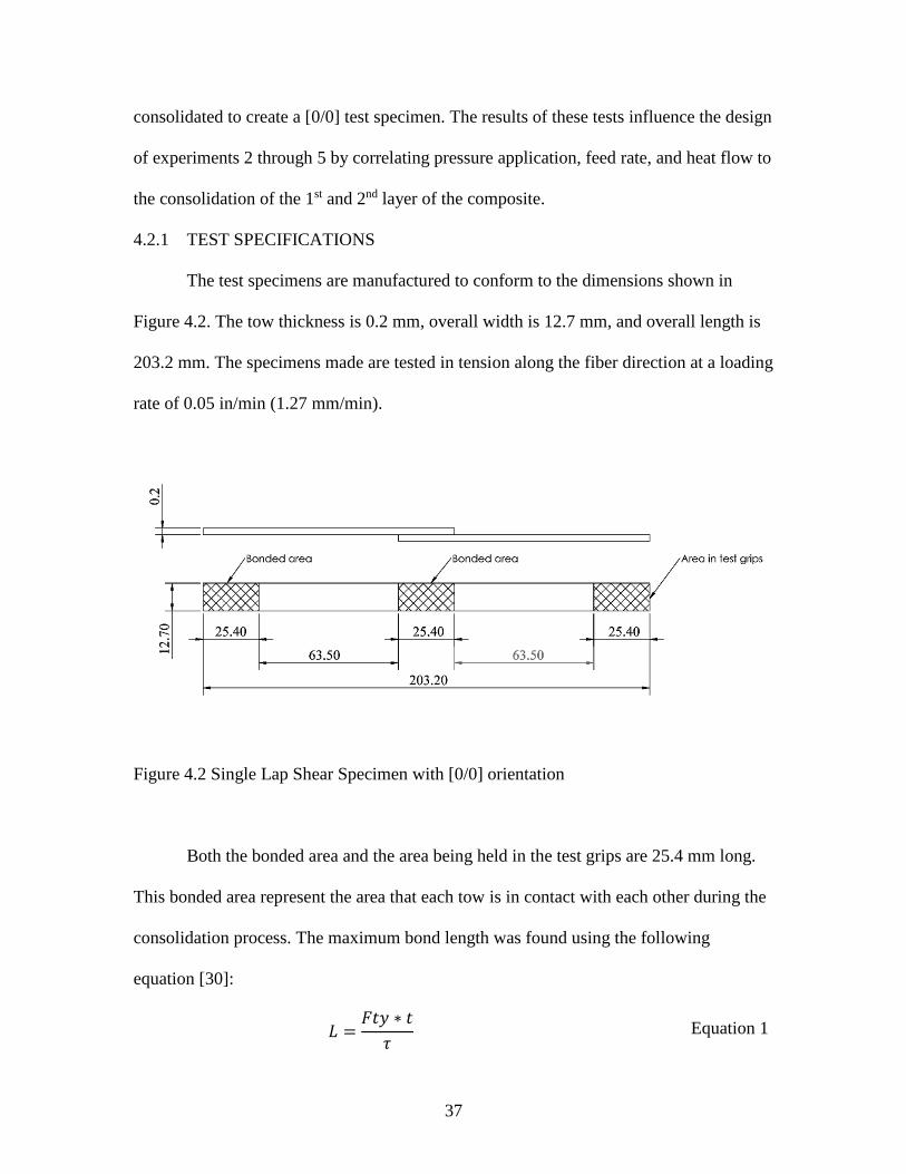
The test specimens are manufactured to conform to the dimensions shown in
Figure 4.2. The tow thickness is 0.2 mm, overall width is 12.7 mm, and overall length is
203.2 mm. The specimens made are tested in tension along the fiber direction at a loading
rate of 0.05 in/min (1.27 mm/min).
Figure 4.2 Single Lap Shear Specimen with [0/0] orientation
Both the bonded area and the area being held in the test grips are 25.4 mm long.
This bonded area represent the area that each tow is in contact with each other during the
consolidation process. The maximum bond length was found using the following
equation [30]:
𝐿 =𝐹𝑡𝑦 ∗ 𝑡
𝜏 Equation 1

38
Where:
L = length of overlap (m), t = thickness of tow (m), Fty = yield stress of the tow (Pa), τ =
150% of the average shear strength (Pa)
The average shear strength at the bonded area was assumed to be equal to that of
ULTEM™ PEI, which has a shear strength of τ = 103.42 MPa. The maximum
permissible length was found to be 28.9 mm. As a result, 25.4 mm (1 in) was chosen as
the appropriate amount of overlap. This equation is usually applied in order to ensure that
the yield stress of the specimen being tested is not exceeded and that the strength of the
bond is actually tested. For these experiments, however, failure due to fiber fracture will
still be considered as acceptable results. Failure of the in-situ consolidation process will
be determined from in-plane shear failure of the bond area at a stress lower than the shear
strength of the PEI thermoplastic resin.
4.2.2 CONTROL SPECIMENS
The control specimens are made using a hot plate where the pressure and
temperature are precisely controlled to make a [0/0] laminate with only a 25.4 mm
bonded area. Multiple specimens were cut from this specimen then tested using the same
single lap shear specifications discussed in the previous section. Figure 4.3 below shows
the laminate made with the hot press.

39
Figure 4.3 Control Specimens
The laminate was fabricated by heating it to 600 °F (315 °C) at a force of 0.3 ton
(2.998 kN). The material was held at that temperature for 3 minutes then cooled at a rate
of 20 °F a minute.
4.3 DRYING OF CARBON/PEI TOWS
All of the material used in this automated fiber placement process was dried prior
to use. The amount of water that is absorbed by the PEI matrix material may cause quite a
bit of problems during consolidation. Research performed by Li [29] report that PEI
begins undergoing thermal degradation at around 460 °C due to scission of the imide
group of the polymer chain from trace water being present. As a result, it is very
important to dry the material to ensure that the thermoplastic is thermally stable.
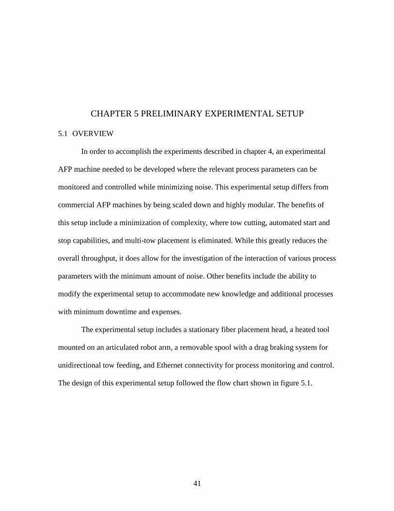
Scrap Material Scrap Material Bonded Area

40
The drying process was performed according to the specifications recommended
by SABIC. The composite tape was dried at a temperature of 140 °C for 6 hours. In
addition, excess material was taken out of the experimental setup and dried again every 2
weeks to ensure that a moisture content of 0.02% is never exceeded.
41
CHAPTER 5 PRELIMINARY EXPERIMENTAL SETUP
5.1 OVERVIEW
In order to accomplish the experiments described in chapter 4, an experimental
AFP machine needed to be developed where the relevant process parameters can be
monitored and controlled while minimizing noise. This experimental setup differs from
commercial AFP machines by being scaled down and highly modular. The benefits of
this setup include a minimization of complexity, where tow cutting, automated start and
stop capabilities, and multi-tow placement is eliminated. While this greatly reduces the
overall throughput, it does allow for the investigation of the interaction of various process
parameters with the minimum amount of noise. Other benefits include the ability to
modify the experimental setup to accommodate new knowledge and additional processes
with minimum downtime and expenses.
The experimental setup includes a stationary fiber placement head, a heated tool
mounted on an articulated robot arm, a removable spool with a drag braking system for
unidirectional tow feeding, and Ethernet connectivity for process monitoring and control.
The design of this experimental setup followed the flow chart shown in figure 5.1.

42
Figure 5.1 AFP Design Flow Chart
The design requirements influence the mechanical, electrical, and software design
of the experimental AFP machine. These designs are all interdependent and influence the
process variables that will be controlled and monitored. The signal variables must be able
to be controlled in-situ while relevant data such as compaction force, tool temperature,
and heating temperature are recorded.
While this experimental setup is not fully automated, this research will influence
the design of a second iteration of an AFP machine for thermoplastic fiber steering. The
next experimental setup should include feedback control, automated start and stop, and

43
multi-tow feeding capabilities in order to improve the process throughput. This will allow
for research to be performed for production scale components.
5.2 FIBER PLACEMENT HEAD
The AFP head consists of a compaction roller, secondary rollers, a primary heat
source, and a secondary heat source. This head allows for the TC1000 tow to be
consolidated under pressure and tension. In addition, this fiber placement head allows for
the addition secondary rollers. Figure 5.2 shows the AFP head with a 4 roller setup and
with 2 hot air heaters.
Figure 5.2 AFP Head with 4 Roller Setup

44
The compaction roller is made of 304 stainless steel, allowing for a polished roller
surface that resists wear and does not adhere to the tow being placed. The secondary
rollers are made of 7075-T6 aluminum, as the primary purpose is to introduce additional
tension into the tow being placed rather than compacting the material under heat. This
allows for a less than perfect surface quality. The dimensions and position of these rollers
are shown in figure 5.3.
Figure 5.3 AFP Head Cross-Section with Dimensions
The rollers and heat sources are spring mounted on linear guides to allow for
control of the compaction force while accommodating for dimensional variance in the
tool surface and position. In addition, a compression load cell is fitted in line with the

45
rollers and the springs in order to provide constant monitoring of the compaction force.
Figure 5.4 below displays the compaction force as a function of compaction roller
displacement. The position of the heated tool, and subsequently the displacement of the
compaction roller, is controlled by positioning the articulated robot arm.
Figure 5.4 Compaction Force vs. Roller Displacement
5.3 HEAT SOURCES
Two different heat methods are being tested: hot air and infrared. Heated gas and
infrared heating are two widely used methods for the heating of thermoplastics in FW and
ATL. The two heaters chosen allowed for the concepts to be tested against each other in a
y = 31.397x
0
50
100
150
200
250
300
0 1 2 3 4 5 6 7 8 9 10
Fo
rce
(N)
Displacement (mm)
Compaction Force

46
cost effective manner. These heaters needed to be able to heat a concentrated area of the
material to a minimum of 317 °C.
The hot air heater consists of a modified HA welder typically used for soldering
electronics. This system allowed for heating of air to a temperature of 480 °C with
additional control of the flow rate. This heater was modified with a heater tip that allows
for a more concentrated heating of the tow being placed, as well as being wired into the
electrical system to allow for automated control during fiber placement. Figure 5.5 shows
the heater being used and the modified tip.
Figure 5.5 303D Hot Air Rework Station and Modified Heater Tip
The infrared heater being tested consists of a handheld infrared welder modified
with a double convex lens. The lens is a 35 mm diameter lens with a 70 mm focal length.
This setup allows for a relatively low cost, 600W IR heater to be used for concentrated

47
heating of the material (not the surrounding air) up to 480 °C very quickly. Figure 5.6
shows the IR heater being tested, with the only modification being the lens.
Figure 5.6 T835 Solder Station
5.4 FIBER TENSIONER
The TC1000 tow being placed is kept in tension using a spool with a friction
based drag brake system. This spool is removable and allows for simple changing of the
material if needed. In addition, the mounting of this spool allows for quick repositioning,
allowing for multiple rows of material to be wound on the same spool and used without
needing to remove the spool. Figure 5.7 shows this system in detail.

48
Figure 5.7 Repositionable Spool with Drag Braking System
In addition to the drag braking system, a spring based tensioner is placed in-line
with the tow before the AFP head. This mechanical tensioner allows for measuring of the
tow tension with either a caliper (using the known spring constant) or a digital force gage.
These two systems together, allow for unidirectional tensioning of the tow that can be
adjusted for various trials. Figure 5.8 below shows this mechanical tensioner fitted with a
force gage.
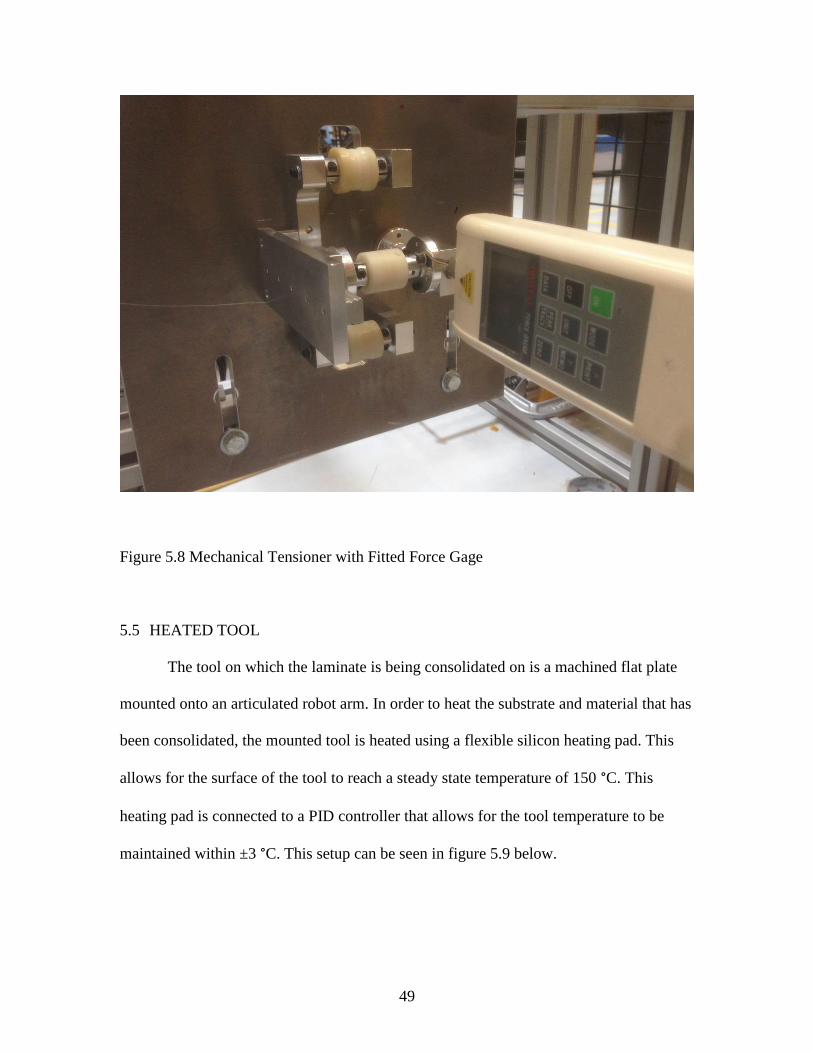
49
Figure 5.8 Mechanical Tensioner with Fitted Force Gage
5.5 HEATED TOOL
The tool on which the laminate is being consolidated on is a machined flat plate
mounted onto an articulated robot arm. In order to heat the substrate and material that has
been consolidated, the mounted tool is heated using a flexible silicon heating pad. This
allows for the surface of the tool to reach a steady state temperature of 150 °C. This
heating pad is connected to a PID controller that allows for the tool temperature to be
maintained within ±3 °C. This setup can be seen in figure 5.9 below.

50
Figure 5.9 Heated Tool and PID Controller Setup
Sonmez and Hahn [3] reported a direct increase in compaction roller speeds with
the pre-heating temperature. While it is possible to cause delamination by heating the
material too much, it is generally desirable to preheat the tool to the highest possible
temperature.
5.6 INTEGRATION WITH ARTICULATED ROBOT ARM
With the AFP head being fixed in place, the tool is moved relative to the head via
6-DOF articulated robot arm. The heated tool is mounted on a KUKA KR60 which is
programmed to move the tool through the appropriate tool path. By programming the
position, velocity, and tool path of the KR60, the feed rate and compaction force
throughout the tow path can be controlled.
Control of the heat sources and data collection is possible by communicating with
the KR60 via an EtherCAT fieldbus system. A digital output terminal allows for any of
the heat sources to be turned on/off by the KR60 controller, while a thermocouple
terminal allows for data to be collected from up to 8 thermocouples. In addition, an

51
analog input terminal allows for infrared temperature sensors (such as the OMEGA®
OS136 Sensor) or compression load cells (OMEGA® LC305) to be connected to the
system. Figure 5.10 shows this EtherCAT fieldbus system as it is connected on the
experimental setup.
Figure 5.10 EtherCAT Fieldbus System and Power Supply
The heat sources are turned on/off throughout the AFP process, however, control
of the temperature must be set beforehand. The sensor readings are recorded throughout
the entire process and can be stored and written to a text file allowing for post-process

52
analysis. Lastly, additional sensors and equipment can be added to this system, such as
solenoids for pneumatic actuation or stepper motors for automated tow feeding.

53
CHAPTER 6 RESULTS AND ANALYSIS
6.1 HEAT SOURCE COMPARISON
Before completing the development of the AFP experimental setup, two different
off-the-shelf welders were tested and compared: a hot air welder and a handheld infrared
welder. The ability of each heater to bring the tow to its recommended processing
temperature (317 °C) and size of their effective heating areas were analyzed.
6.1.1 HOT AIR HEATER
With a 1/8” inner diameter tip fitted, the hot air welder worked very well for
heating a single tow with minimal heating of the surrounding area. When analyzing the
effect of tool temperature on the resulting temperature of the material being heated, there
was a dramatic effect when increasing the tool from 100 °C to 120 °C. The difference in
the average temperature of the material when increasing from 120 °C to 140 °C, however,
is negligible. This can be seen in figure 6.1, where the average temperatures reached by
the material are plotted against the heater temperature setting.

54
Figure 6.1 Average Material Temperatures vs. HA Heater Temperature Setting
Figure 6.1 also shows the dramatic affect that the distance of the heater tip to the
material plays on the resulting material temperature. Table 6.1 below displays the average
and maximum temperatures reached by the material at both distances tested, where Th =
450 °C and Tt = 140 °C. In addition, the length of time until the material reached a steady
state temperature is also listed.
Table 6.l Material Temperatures Reached for h1 = 10 mm and h2 = 15 mm
Distance to Tool Surface, h mm 10 15
Average Temperature, Tavg °C 244.9 206
Max Temperature, Tmax °C 247 210
Time to Steady State, tss s 60 50
120
140
160
180
200
220
240
260
320 340 360 380 400 420 440 460
T (
°C)
Th (°C)
Average Temperature vs. Hot Air Heater Setting
h=10mm, Tt=100C
h=15mm, Tt=100C
h=10mm, Tt=120C
h=15mm, Tt=120C
h=10mm, Tt=140C
h=15mm, Tt=140C

55
When analyzing how the heater setting affects the resulting material temperature,
in was seen that the distance h affects the difference in temperature reached by the
material. A 50 °C change in the heater temperature setting results in roughly a 23.5 °C
change in the material temperate when h = 10 mm. This difference markedly decreases
when the distance increases to h = 15 mm. Most importantly, there was a dramatic
difference in the hot air heater temperature setting to the temperature of the material and
failed to bring the tow to its Tg of 317 °C for these settings. These results can be seen in
figure 6.2, where material temperatures reached are plotted for various primary heater
settings as a function of time.
Figure 6.2 Material temperature as a function of time for h = 10mm
0
50
100
150
200
250
300
0 20 40 60 80 100
T (
°C)
t (s)
Material Temperatures Reached, h = 10 mm
Th=350C
Th=400C
Th=450C
Avg Temp (Th=350C)
Avg Temp (Th=400C)
Avg Temp (Th=450C)

56
Decreasing the heater tip position to the material solved this problem, however.
By bringing the heater tip to roughly 5 mm from the surface of the material, temperatures
up to 420 °C were achievable at a tool temperature of Tt = 150 °C. With these
adjustments, the hot air heating setup allowed for the correct amount of heating of the
tow being placed and little of the surrounding material. This system does not leave much
room for adjustment of the temperature; however, building on this concept and using a
purpose built hot gas system will solve this. In addition, switching from air to an inert gas
as the working fluid for heating is another modification that will allow for greater heating
with less thermal degradation. For those reasons, this type of heating system is widely
used in ATL [3] [2] and AFP [22] [31].
6.1.2 INFRARED HEATER
With the same experiments performed using the IR heater (experiment 1, trials 19
– 36), it became immediately clear that the most important parameter influencing the
material temperature reached is distance to the tool. At the distances tested, the IR heater
with the double convex lens failed to bring the material up to the pre-set heater
temperature. By bringing the heater to a distance of roughly 5 mm, however, the material
heated up extremely quickly. This can be seen in figure 6.3, where the temperature
reached by the material is plotted against time for a distance of h = 5 mm and a tool
temperature of Tt = 150 °C.

57
Figure 6.3 IR heating over time with h = 5 mm, Tt = 150 °C
The time taken to reach a steady state temperature reached is very quick, reaching
the set temperature of 450 °C in roughly 5 seconds. Once it reaches the appropriate
temperature, he programming set by this heater cuts power and causes the temperature to
drop roughly 8 degrees before it begins heating it back to the pre-set temperature. This is
a problem that can be corrected with a purpose built IR heater with variable light
intensity.
While the ability to heat the material to very high temperatures extremely quickly
makes this system much more powerful than the HA system that was tested, the heated
area was far to concentrated to be used effectively. In addition, this system requires that
the heater is very close to the material and is exactly perpendicular to the tool surface.
This means that the heater must be between two compaction rollers or compliant shoes.
While these problems made this heating system a bit too unwieldy for the rest of the
0
50
100
150
200
250
300
350
400
450
500
0 5 10 15 20 25 30 35
T (
°C)
time (s)
IR Heating at h = 5 mm, Tt = 150 °C

58
experiments, designing a new AFP head and IR heating system made to work
synergistically may yield great benefits. Higher material throughput may be achieved at a
fraction of the cost of a laser heating system with a higher amount of control than a hot
gas system.
6.2 HEATING LIMITATIONS
6.2.1 PRIMARY HEAT APPLICATION
The results of experiment 2 showed a clear result when it came to identifying the
affect heating the material being fed has on the maximum feed rate that is achievable.
With a HA system, the maximum temperature that the system can reach (480 °C) is the
minimum temperature that was feasible for this experimental setup. The feed rates
necessary for consolidation of the material is still too low to warrant reducing the primary
heater temperature. While the feed rates do improve significantly at higher number of
layers, there is still little reason to lower the heater temperature as no noticeable
degradation was observed. The relationship between the number of layers and the feed
rate will be discussed in a later section.
There are some constraints that must be taken into account, however. While
increasing the applied should directly improve the feed rate, thermal degradation of the
thermoplastic may occur as a result. Li [29] reported significant thermal degradation of
PEI near 535 °C. It is important to note that this was found using a heating rate of 10
°C/min, resulting in a total time of 13.5 minutes where the material was between 400 °C
to 535 °C. During the AFP process, this overall soak time is significantly less and may
allow for elevated temperatures to be used in the process. This concept was discussed by

59
August et al in there publication detailing the AFP process developed by Automated
Dynamics® [25].
6.2.2 SECONDARY HEAT APPLICATION
By using a stainless steel compaction roller, a significant amount of the heat
applied to the tow being placed is absorbed and dissipated by the roller. In addition, using
a larger diameter roller to increase the feed rate would magnify this problem. In order to
combat this problem, it was necessary to use a secondary HA heater that allowed for
heating of the compaction roller and heat affected zone. The placement of the secondary
heater, along with the heat shield setup, can be seen in figure 6.4.
Figure 6.4 Secondary and Primary Heater Positioning

60
This secondary heated was able to increase the temperature of the main and
secondary rollers to roughly 150 °C by setting the temperature to a maximum setting of
480 °C. Improving the heat shielding and better managing the heat flow will greatly
decrease the heat losses. By increasing the overall temperature of the heat affected zone,
more of the applied heat from the primary heater is absorbed by the material and promote
polymer diffusion. In addition, the temperature gradient from the tool to the secondary
rollers is minimized, allowing for a reduced cooling rate while the material is being
compacted. Decreasing this temperature gradient is critical for eliminating delamination
due to rapid cooling under a sudden release of compaction pressure and tension.
6.2.3 TOOL TEMPERATURE
As mentioned in section 6.1.1, heating the tool allows for increasing the
maximum temperature reached by the material being placed. As a result, the overall feed
rate is improved by increasing the tool temperature. The same result was reported by
Sonmez and Hahn [3], where linear increases in roller speeds were achieved with
increasing pre-heating temperatures. For the laminate layup, the tool temperature was
kept at 150 °C. This was limited by the silicon heating pad, which became unreliable
beyond 155 °C. With this combination of tool temperature, primary, and secondary heater
settings, a temperature of roughly 500 °C was achieved at the nip region.
6.3 COMPACTION PRESSURE
6.3.1 INFLUENCE OF COMPACTION FORCE
Upon performing experiments 3 and 4, no correlation could be found between the
compaction forces, number of rollers, and tow tension with feed rate. Altering the
compaction pressure does indeed affect the degree of bond. The compaction pressure is a

61
function of compaction force, roller diameter, and number of rollers. Table 6.2 shows the
maximum pressure at each of rollers for the 3 different compaction forces tested.
Table 6.2 Compaction pressure at each of the rollers (MPa)
Number of Rollers, Nr 4 3 2
Roller Primary Secondary Primary Secondary Primary Secondary
Compaction Force (N)
F = 314 52.321 106.819 61.907 126.390 79.922 163.169
F = 220 43.795 89.412 51.819 105.793 66.898 136.579
F = 157 36.997 75.532 43.775 89.371 56.514 115.378
These pressures were found by measuring the compaction force and using the
calculation for maximum pressure shown in Equation 2 below:
𝑃𝑚𝑎𝑥 =2𝐹𝑐
𝜋𝑏𝑙
Equation 2
This equation is used for calculation of Hertzian contact stresses, where b is the
half width of the theoretical contact width of the roller to the material. It was found that if
the compaction pressure was too low, consolidation did not occur regardless of the feed
rate or the applied heat. In addition, increasing the compaction pressure too much
negatively affect the bond as well. While 314 N was found to be the ideal compaction
pressure based on the control factor settings chosen, no detrimental effects were seen
from a range of 300 N to 320 N. Limitation in the experimental setup did not allow for
increasing the load beyond 320 N.
As the numbers of rollers are decreased, the compaction force must also be
decreased in order to consolidate the material being placed. Table 6.3 plots the decrease
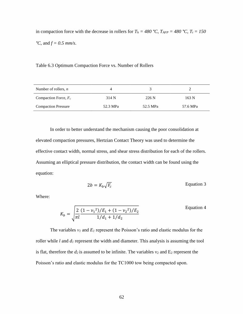
62
in compaction force with the decrease in rollers for Th = 480 °C, TAFP = 480 °C, Tt = 150
°C, and f = 0.5 mm/s.
Table 6.3 Optimum Compaction Force vs. Number of Rollers
Number of rollers, n 4 3 2
Compaction Force, Fc 314 N 226 N 163 N
Compaction Pressure 52.3 MPa 52.5 MPa 57.6 MPa
In order to better understand the mechanism causing the poor consolidation at
elevated compaction pressures, Hertzian Contact Theory was used to determine the
effective contact width, normal stress, and shear stress distribution for each of the rollers.
Assuming an elliptical pressure distribution, the contact width can be found using the
equation:
2𝑏 = 𝐾𝑏√𝐹𝑐 Equation 3
Where:
𝐾𝑏 = √2
𝜋𝑙
(1 − 𝜈12) 𝐸1⁄ + (1 − 𝜈2
2) 𝐸2⁄
1 𝑑1⁄ + 1 𝑑2⁄
Equation 4
The variables ν1 and E1 represent the Poisson’s ratio and elastic modulus for the
roller while l and d1 represent the width and diameter. This analysis is assuming the tool
is flat, therefore the d2 is assumed to be infinite. The variables ν2 and E2 represent the
Poisson’s ratio and elastic modulus for the TC1000 tow being compacted upon.

63
The normal stress at the surface of the tow, where the roller and the material come
into contact, is found using the following equation for the maximum pressure at the
central line of contact:
𝜎𝑧 = −𝑃𝑚𝑎𝑥 = −2𝐹𝑐
𝜋𝑏𝑙
Equation 5
Hertzian Contact Theory assumes an elliptical pressure distribution caused by the
roller pressing on the surface of the tool. With the maximum normal stress and contact
width known for the roller being using in this experimental setup, this assumption allows
us to plot the pressure distribution. Figure 6.5 displays the pressure distribution for the
primary roller at various compaction forces for a setup with 3 secondary rollers. Figure
6.6 displays the same analysis for the secondary rollers.
Figure 6.5 Normal Stress for Primary Roller vs. Compaction Force (Nr = 4)
-52.321
-43.795
-36.997
-60
-50
-40
-30
-20
-10
0
-0.05 -0.03 -0.01 0.01 0.03 0.05
Str
ess
(MP
a)
Distance from Roller Contact (mm)
Hertzian Normal Stress Distribution for Primary Roller
Fc = 314 N
Fc = 220 N
Fc = 157 N

64
Figure 6.6 Normal Stress for Secondary Rollers vs. Compaction Force (Nr = 4)
While increasing the compaction force increases the contact width, allowing for a
longer dwell time where the composite will be heated and under pressure, it also
increases an already high normal stress. For a 4 roller setup, a compaction force of 314 N
was found to result in acceptable consolidation of the material. This high pressure helps
promote autohesion and reduce the formation of voids, however, the small contact width
results in a very high stress concentration that should be avoided. This is caused by the
relatively small roller size and the high stiffness of stainless steel.
In addition to looking at the normal stress at the surface of the tow, the shear
stress through the depth of the material was also analyzed using the following expression:
𝜏𝑚𝑎𝑥 = {𝜏13 = (𝜎𝑧 − 𝜎𝑥) 2 𝑓𝑜𝑟 0 ≤ 𝜁𝑏 ≤ 0.436 ⁄
𝜏13 = (𝜎𝑧 − 𝜎𝑦) 2 𝑓𝑜𝑟 0.436 ≤ 𝜁𝑏⁄ Equation 6
Where:
𝜁𝑏 =𝑧
𝑏 Equation 7
-106.819
-89.412
-75.532
-120
-100
-80
-60
-40
-20
0
-0.03 -0.02 -0.01 0.01 0.02 0.03
Str
ess
(MP
a)
Distance from Roller Contact (mm)
Hertzian Normal Stress Distribution for Secondary Rollers
Fc = 314 N
Fc = 220 N
Fc = 157 N

65
And:
Z = distance below the material’s surface
The maximum shear stress through the thickness of the material was plotted
against for the three different compaction forces. This analysis is shown in figure 6.7 for
a roller setup of Nr = 4.
Figure 6.7 Shear Stress Distributions for Various Compaction Forces
While the shear stresses do increase for compaction forces as high as 314 N, this
occurs at a depth between 0.3 mm and 0.4 mm and is relatively low when compared to
the very high normal stress distribution. It must be noted that this analysis is performed
with no heating of the roller or material being compacted. At the elevated temperatures
-15.591
-13.140
-10.936
-18.00
-16.00
-14.00
-12.00
-10.00
-8.00
-6.00
-4.00
-2.00
0.00
0 0.01 0.02 0.03 0.04 0.05 0.06 0.07 0.08 0.09 0.1 0.11
Str
ess
(MP
a)
Z, Distance below surface (mm)
Hertzian Shear Stress Distribution for Nr = 4
Tmax_zx (F = 314 N)
Tmax_zy (F = 314 N)
Tmax_zx (F = 220 N)
Tmax_zy (F = 220 N)
Tmax_zx (F = 157 N)
Tmax_zy (F = 157 N)

66
needed to consolidate the tow, these high stress concentrations pose a problem that must
be managed with careful control of the compaction force.
6.3.2 ROLLER DIAMETER
While this experimental setup used a single compaction roller with a diameter of
70 mm, it appears that increasing the roller size will allow for higher feed rates. In order
to analyze the effect of increasing the roller diameter, the contact width and normal stress
was plotted against the roller diameter. This is shown in figure 6.8 for a stainless steel
roller where Nr = 4.
Figure 6.8 Contact Widths and Normal Stress vs. Roller Diameter
By increasing the contact width from 70 mm to 140 mm, the contact width
increases from 0.08 mm to 0.12 mm. The maximum normal stress at the center of the
roller decreases from -52.32 MPa to -37.00 MPa. While these changes do not appear to
0
0.01
0.02
0.03
0.04
0.05
0.06
0.07
-70
-60
-50
-40
-30
-20
-10
0
40 60 80 100 120 140 160
Wid
th (
mm
)
Str
ess
(MP
a)
Diameter (mm)
Contact Width and Normal Stress vs. Roller Diameter
Stainless Steel Roller
Stress (sigmaZ)
1/2 Contact Width

67
be very significant, they will indeed improve consolidation as the normal stresses become
less concentrated. A more in-depth analysis should be performed in order to fully
determine the potential increases in feed rate and process throughput.
6.3.3 INFLUENCE OF ADDITIONAL ROLLERS ON TOW TENSION
It has already been discussed how adding the additional rollers reduces the overall
compaction pressure on the material. While this alone does not actually translate to an
improvement in consolidation, adding additional rollers along with a primary compaction
roller does indeed improve consolidation and improve feed rate. The mechanism behind
this improvement is the increase in tow tension post compaction from the primary roller.
Without the secondary rollers, unreasonable feed rates below 0.2 mm are needed
for achieving very mediocre in-situ consolidation at n = 2 with the primary and
secondary heaters set to 480 °C. The lowest tow tension is needed (Ft = 5 N), as the bond
strength is weak and increasing the tow tension will add in-plane shear stresses that cause
delamination. Adding addition rollers increases the tension to the tow post compaction,
effectively increasing the dwell time and improving consolidation. In addition, increasing
the length of the heated zone by adding more secondary rollers allows for the
consolidated tow to cool down without a sudden release of tension and pressure. The use
of a compaction shoe or track system rather than secondary rollers may provide the same
benefits with a greater distribution of pressure.
The ideal compaction forces for the second layer consolidation were found and
single lap shear specimens were manufactured, tested, and compared with the control
specimens described in section 4.4.2. The results of these tests are listed below in table
6.4.
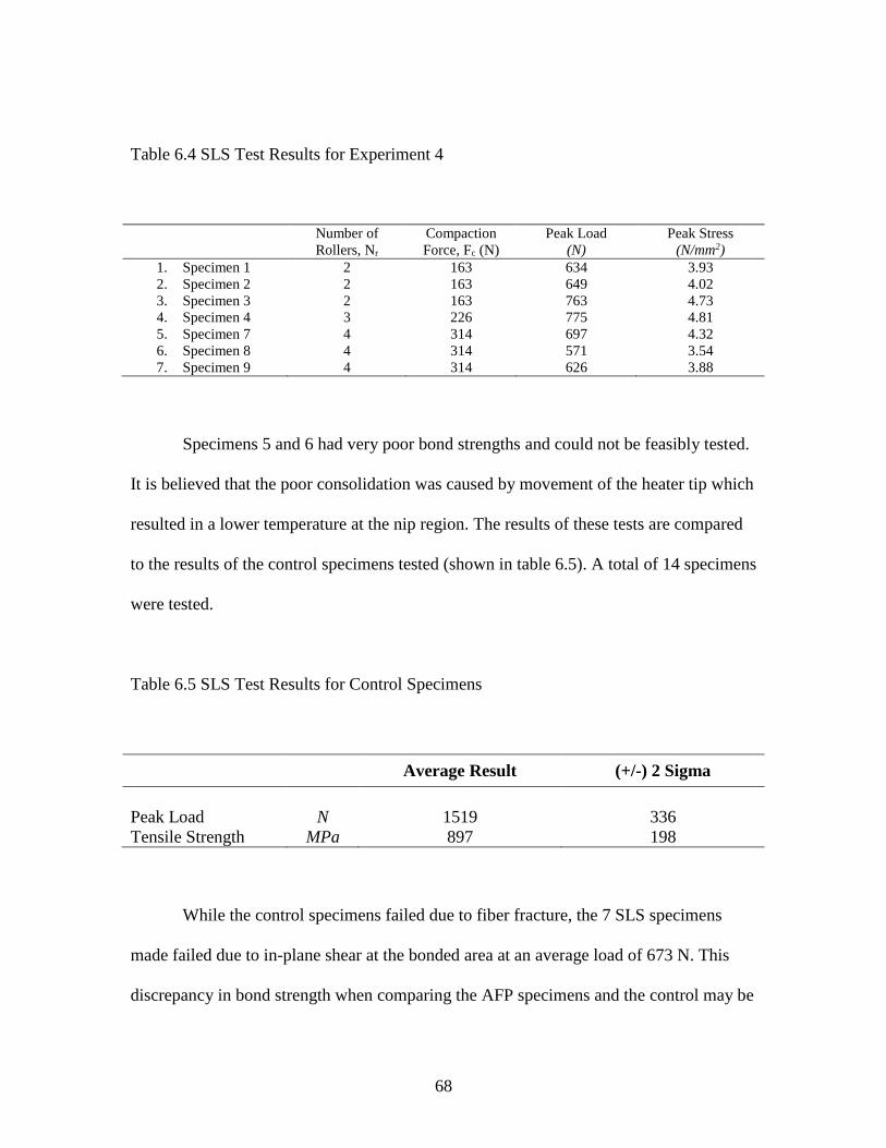
68
Table 6.4 SLS Test Results for Experiment 4
Number of
Rollers, Nr
Compaction
Force, Fc (N)
Peak Load
(N)
Peak Stress
(N/mm2)
1. Specimen 1 2 163 634 3.93
2. Specimen 2 2 163 649 4.02
3. Specimen 3 2 163 763 4.73
4. Specimen 4 3 226 775 4.81
5. Specimen 7 4 314 697 4.32
6. Specimen 8 4 314 571 3.54
7. Specimen 9 4 314 626 3.88
Specimens 5 and 6 had very poor bond strengths and could not be feasibly tested.
It is believed that the poor consolidation was caused by movement of the heater tip which
resulted in a lower temperature at the nip region. The results of these tests are compared
to the results of the control specimens tested (shown in table 6.5). A total of 14 specimens
were tested.
Table 6.5 SLS Test Results for Control Specimens
Average Result (+/-) 2 Sigma
Peak Load N 1519 336
Tensile Strength MPa 897 198
While the control specimens failed due to fiber fracture, the 7 SLS specimens
made failed due to in-plane shear at the bonded area at an average load of 673 N. This
discrepancy in bond strength when comparing the AFP specimens and the control may be

69
explained by some results reported by Sonmez and Hahn, where it was stated that
additional consolidation occurs with subsequent passes during the next layer [3].
6.4 TOW TENSION
It was mentioned in section 6.3.3 that minimal tow tension was needed without
the use of the secondary rollers. With the use of these rollers, however, tow tension was
not found to influence the bond. This is due to the amount of compaction pressure used in
the experimentations, where increasing the tow tension to 15 N was not detrimental. A
problem does occur when starting the tow, as high tow tension causes delamination while
the tow is not under pressure from both the primary and secondary rollers. It is
recommended that tow tension is kept at a minimum when restarting tow placement, then
increased after a short time in order to improve tow straightness. It is possible that tow
tension can be maximized as a function of compaction pressure, but more experiments
with a higher resolution is needed.
6.5 FEED RATE AND PLY NUMBER
It was found that the feed rate does indeed increase with the number of layers that
have been consolidated. As it has been previously mentioned, feed rates of 0.5 mm/s was
found to be optimal with n = 2. This increases up to 3.5 mm/s when performing laying-
up on 7 layers (n = 7). This result is also reported by Sonmez and Hahn [3]. It should be
noted that they recommend slowing the speed for the last layer in order to achieve a
greater bond strength; however, this was not investigated in this report. The list of feed
rates achieved can be seen in table 6.6 below.

70
Table 6.6 Results for Experiment 5
Number of layers, n 3 5 7
Feed rate, f mm/s 2.5 3.0 3.5
Figure 6.9 shows an example of two layups at different speeds. As previously
mentioned, the compaction pressure of 52 – 57 MPa was necessary to achieve in-situ
consolidation. It is possible that the compaction pressure can be lowered when increasing
the number of layers, but more experimentation and a true sensitivity analysis is needed.
Figure 6.9 Layup on 3 layers (n = 3) at f = 3 mm/s (left) and f = 2.5 mm/s (right)

71
6.6 LAMINATE MANUFACTURING CHALLENGES
With the current experimental setup, layup of the 8 layer laminate was not ideal.
While process characterization was performed, identifying a window of operation that
allows for the layup of the 8 layers, there are several challenges that must be addressed
before a truly automated in-situ consolidation process can be used.
6.6.1 SUBSTRATE AND FIRST TWO LAYERS
When the process settings for experiment 2 were given in section 4.1.2, the
number of layers upon which in-situ consolidation would take place was set to n = 2.
When experimenting with this material, it became clear that in-situ consolidation of the
TC1000 tow was not possible during the first 2 layers. With the current tool, AFP head,
and heat source, a minimum of 2 layers is needed to begin in-situ consolidation.
One of the largest problems stems from the fact that large amounts of heat
supplied at a very low feed rate is needed during the first few layers. In order to
consolidate the material on the first layer, a suitable substrate is needed where the first
layer of tows can be bonded to. This substrate must be able to temporarily bond to the
tows, allowing for the laminate to be removed when the entire layup is complete. The use
of raw PEI as a substrate can be used as a suitable substrate, acting as a surface that can
be bonded to and become part of the structure. While this works well for the layup of the
first layup, the needed heat and long dwell time the first layer is exposed to during the
layup of the second layer causes the PEI substrate to severely degrade and cause
irreparable damage.
During their analysis of ATL of APC-2, Sonmez and Hahn [3] reported some
interesting findings that may explain the excessive dwell times needed at the lower
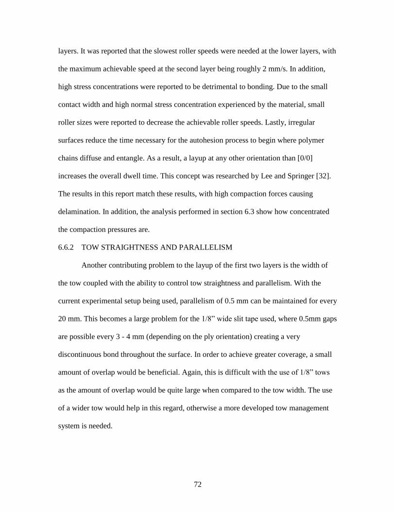
72
layers. It was reported that the slowest roller speeds were needed at the lower layers, with
the maximum achievable speed at the second layer being roughly 2 mm/s. In addition,
high stress concentrations were reported to be detrimental to bonding. Due to the small
contact width and high normal stress concentration experienced by the material, small
roller sizes were reported to decrease the achievable roller speeds. Lastly, irregular
surfaces reduce the time necessary for the autohesion process to begin where polymer
chains diffuse and entangle. As a result, a layup at any other orientation than [0/0]
increases the overall dwell time. This concept was researched by Lee and Springer [32].
The results in this report match these results, with high compaction forces causing
delamination. In addition, the analysis performed in section 6.3 show how concentrated
the compaction pressures are.
6.6.2 TOW STRAIGHTNESS AND PARALLELISM
Another contributing problem to the layup of the first two layers is the width of
the tow coupled with the ability to control tow straightness and parallelism. With the
current experimental setup being used, parallelism of 0.5 mm can be maintained for every
20 mm. This becomes a large problem for the 1/8” wide slit tape used, where 0.5mm gaps
are possible every 3 - 4 mm (depending on the ply orientation) creating a very
discontinuous bond throughout the surface. In order to achieve greater coverage, a small
amount of overlap would be beneficial. Again, this is difficult with the use of 1/8” tows
as the amount of overlap would be quite large when compared to the tow width. The use
of a wider tow would help in this regard, otherwise a more developed tow management
system is needed.

73
6.6.3 HEATING AT THE NIP REGION
The final problem that must be addressed is in the amount of heat being applied at
the nip region. With the current experimental setup, the temperature and flow rate of the
heated air can be preset, but these parameters cannot be controlled in-situ. After the
system is warmed up, the heated area at the nip is wide enough to consolidate up to 3
tows at once (0.375”). Since the current system is designed to feed and consolidate 1 tow,
this amount of heat causes the surrounding tows to warp and possibly delaminate. This
problem, coupled with challenges maintaining tow parallelism, makes in-situ
consolidation of the first 2 layers extremely difficult. Figure 6.10 below shows an
example these problems being coupled. The small gaps are caused by the varying tow
position, the missing tows are a result of excessive heat while not under pressure causing
delamination, and the waviness in the previous layer is the result of not using a substrate.
Figure 6.10 In-situ consolidation challenges during the layup of the 3rd layer

74
6.6.4 POTENTIAL SOLUTIONS
The most obvious solution to some of these challenges comes from improving the
precision of the heat application, allowing for the exact amount of material being
compacted to be heated. While hot air/gas heaters are by nature less precise than a laser
heating system or an IR heater similar to what was tested in this report, there are several
modifications that can be made in order to correct the problems that currently exist.
Switching from this modified heater to a purpose built HA heater that can be controlled
in-situ will greatly improve the precision. In addition, using a wider roller will also
mitigate the problems associated with the width of the heated region at the nip region.
Using a wider tow will also help in this regard, as more of the tow will be bonded
when it is first placed. As previously mentioned, using a wider tow will also aid in the
layup of the first 2 layers while also greatly increasing the process throughput. Increasing
the tow width used will limit any steering that will be done, however.
6.7 FIBER STEERING
With the fabrication of a working experimental AFP machine and the interaction
of the process parameters investigated, fiber steering was attempted. As identifying the
limits of fiber steering with thermoplastic composites is beyond the scope of this
research, these trials were only performed in order to determine whether the current setup
and process could be applied to the fabrication of VSC. Fiber steering at a radius of 200
mm was achieved with the 1/8” carbon/PEI slit tape and can be seen below in figure 6.11.
75
Figure 6.11 Fiber steering trials at a radius of 200 mm

76
CHAPTER 7 CONCLUSIONS
In order to investigate the interaction of process parameters necessary for in-situ
consolidation of thermoplastic composites with a PEI matrix material, an experimental
AFP machine was developed. In order to develop this experimental setup, different
heating systems were compared and analyzed. Various experiments were then performed
in order to determine the influence compaction pressure, heat application, tool
temperature, and tow tension have on the lay-up. In addition, the change of these
parameters as the number of layers consolidate increases was also investigated. The
results from these experiments help characterize the process, and are as follows:
- Both the HA and IR heating systems can be used for in-situ consolidation of
carbon/PEI slit tape in an AFP process. The HA system provides simple and effective
heating that is easily controlled, however, careful positioning of the tip is needed and
the heated region at the nip is significantly greater than the IR system.
- An IR heating system can be used, however, the size and position of the lens limits
the design of the AFP head. If this constraint can be addressed, however, heating of
the material can be performed with greater precision, at faster feed rates, and at a
fraction of the cost of a laser heating system.
77
- The current feed rates achieved (f = 0.5 – 3.5 mm/s) indicate that heating of the
material at the nip region below 480 °C is not advisable. While material degradation
for PEI has been reported to begin at around 500 °C, no detrimental effects were seen
for temperatures between 480 – 520 °C at the nip region. It is possible that high
heating can allow for higher feed rates.
- Maintaining the appropriate compaction pressure is critical to the consolidation of the
tow, with a range of 52 – 58 MPa found to be acceptable. Increasing the compaction
pressure results in highly concentrated normal stresses that has detrimental effects. A
consolidation pressure that is too low does not promote diffusion of the polymer
chains at manufacturing speeds.
- The addition of secondary rollers is very beneficial to the in-situ consolidation of the
material due to an increase in tow tension between the primary and secondary roller.
While the distance between both rollers is desired to be as small as possible,
increasing the heated length by the addition of multiple secondary rollers may aid the
process by allowing the material to cool under pressure and tension.
- Tow tension must be kept at a minimum (≤ 5 N) when starting the fiber placement.
When the secondary roller comes in contact with the tow, however, tow tension can
be increased in order to improve tow straightness. With the use of secondary rollers,
tow tension did not affect the bond strength at the range tested in this report.
- The achievable feed rates did indeed increase as a function of layer number. During
the lay-up of the 8th layer, feed rates of 3.5 mm/s were achieved.
- The second iteration of this experimental setup, where further automation of the
process will be implemented, should address the heat application at the nip region and

78
better manage the tow placement in order to manufacture a laminate. The use of
wider tows is also recommended, in only for the first and last 2 layers.
- Layup of the first 2 layers was not possible. While use of wider tows will yield
beneficial results, research into the substrate used and method it is applied should be
performed.
- Fiber steering is possible at a radius of 200 mm when using a 1/8” tow; however,
more experiments are needed to fully investigate this process.
With this information, the development of a second experimental setup where tow
cutting and automated tow feeding is incorporated. If the recommended changes are
adopted, large improvements in process throughput will be seen and large scale
thermoplastic composite laminates can be fabricated. Lastly, research into the fabrication
of thermoplastic variable stiffness composites can begin.

79
CHAPTER 8 FUTURE WORK AND RECOMMENDATIONS
Since a sensitivity analysis has yet to be performed, the first recommendation is
that the control factors be narrowed and more concise experiments are performed. This
will allow for a much greater understanding on how each process parameter can be
altered in-situ or whether or not this level of control is actually needed for certain control
factors. In order to perform this analysis, it is recommended that a laminate be
manufactured for each trial from which a test specimen can be cut. The SLS specimens
used in this report only identify the bond strength between 2 plies and the additional
consolidation that occurs as a result of placement of subsequent plies is not taken into
account.
As previously mentioned, the fabrication of a second experimental setup that is
truly automated is required for further research. While this setup still has utility in
performing additional experiments at different control factor settings, the lack of control
gained by addressing the problems previously described will unnecessarily hinder
progress. The development of this experimental setup was started, with the orientation of
the rollers and heaters influenced by the current setup. A rendering of this second
iteration of a thermoplastic AFP machine can be seen in figure 8.1 below.

80
Figure 8.1 Second prototype for a thermoplastic AFP machine
Rather than using linear compression springs, this prototype utilizes a pneumatic
actuator for continuously maintain a preset compaction force. In addition, tow cutting and
automated tow feeding is incorporated. This design does not allow for larger compaction
rollers to be used, however, and allowing for various roller diameters to be used may aid
in future experimentations.
Investigation into the effect of roller diameter may be beneficial. This depends
entirely on the tooling requirements, as using a roller that is too large will limit the
laminate shapes that can be manufactured. By identifying the potential feed rate
improvements, a true design optimization can be performed.

81
Investigation into addition heat sources may be beneficial. As seen in the current
thermoplastic AFP industry, laser heating may yield large improvements in process
throughput. Due to the costs associated with such a heating system, there may be cause to
develop an AFP machine to utilize a purpose built IR heater with a double convex lens.
With the current machine setup, switching to a heated gas system is feasible with
minimal changes to the design. In addition, the heater orientation lends itself to swapping
the HA heater wand with a laser heater if that option is investigated at a later date.
Performing fiber steering experiments are now possible and research into the
minimum turn radius for various tow widths would be beneficial. This research will allow
for a gap in VSC design research to be bridged by identifying manufacturing constraints.
Tow straightness, surface variations at each layer, minimum turn radius, and identifying
when process induced defects occur will improve the variable stiffness laminate designs.
Lastly, research into the use of additional thermoplastic matrix materials is
possible. While PEEK is a commonly used thermoplastic used in various in-situ
consolidation processes, slit tape with other thermoplastic matrix materials such as PPS
and PEKK is also possible
82
REFERENCES
[1] R. Moon, C. Johnson, and R. Hale, “Nondestructive evaluation and mechanical
testing of steered fiber composites,” in 47 th International SAMPE Symposium and
Exhibition 2002, 2002, pp. 1550–1563.
[2] K. A. P. J.A. Mondo, “Performance of In-Situ consolidated Thermoplastic
Composite Structure,” International SAMPE Technical Conference, vol. 27, no.
361–370, 1995.
[3] F. O. Sonmez and H. T. Hahn, “Analysis of the on-line consolidation process in
thermoplastic composite tape placement,” Journal of Thermoplastic Composite
Materials, vol. 10, no. 6, pp. 543–572, 1997.
[4] M. Hyer and R. Charette, “Innovative design of composite structures: use of
curvilinear fiber format to improve structural efficiency,” 1987.
[5] R. Sharp, S. Holmes, and C. Woodall, “Material Selection/fabrication issues for
thermoplastic fiber placement,” Journal of Thermoplastic Composite Materials, vol.
8, no. 1, pp. 2–14, 1995.
[6] A. Deturk, R. Diaz, G. Digiovanni, and B. Hyman, “Exploratory tests on fiber-
reinforced plates with circular holes under tension.,” AIAA Journal, vol. 7, no. 9, pp.
1820–1821, 1969.
[7] H.-J. L. Dirk, C. Ward, and K. D. Potter, “The engineering aspects of automated
prepreg layup: History, present and future,” Composites Part B: Engineering, vol.
43, no. 3, pp. 997–1009, 2012.
[8] K. C. Wu, Z. Gürdal, and J. H. Starnes, “Structural response of compression-loaded,
tow-placed, variable stiffness panels,” in Proceedings of the 43rd
Aiaa/Asme/Asce/Ahs/Asc structures, structural dynamics and materials conference,
Denver, Co, 2002, pp. 2002–1512.
[9] W. Goldsworthy, E. Hardesty, and H. Karlson, “Geodesic path length compensator
for composite-tape placement head,” 1974.
[10] Z. Gurdal and R. Olmedo, “In-plane response of laminates with spatially varying
fiber orientations-variable stiffness concept,” AIAA journal, vol. 31, no. 4, pp. 751–
758, 1993.

83
[11] A. W. Blom, C. S. Lopes, P. J. Kromwijk, Z. Gurdal, and P. P. Camanho, “A
theoretical model to study the influence of tow-drop areas on the stiffness and
strength of variable-stiffness laminates,” Journal of composite materials, 2009.
[12] J. M. Van Campen, C. Kassapoglou, and Z. Gürdal, “Generating realistic laminate
fiber angle distributions for optimal variable stiffness laminates,” Composites Part
B: Engineering, vol. 43, no. 2, pp. 354–360, 2012.
[13] G. Thuwis, M. Abdalla, and Z. Gürdal, “Optimization of a variable-stiffness skin for
morphing high-lift devices,” Smart materials and structures, vol. 19, no. 12, 2010.
[14] K. Fayazbakhsh, D. Pasini, and L. Lessard, “The effect of manufacturing
parameters on the tow drop regions of a variable stiffness composite cone made out
of Automated Fiber Placement,” 42nd ISTC. Salt Lake, City, UT, 2010.
[15] K. Croft, L. Lessard, D. Pasini, M. Hojjati, J. Chen, and A. Yousefpour,
“Experimental study of the effect of automated fiber placement induced defects on
performance of composite laminates,” Composites Part A: Applied Science and
Manufacturing, vol. 42, no. 5, pp. 484–491, 2011.
[16] K. Fayazbakhsh, M. A. Nik, D. Pasini, and L. Lessard, “Defect layer method to
capture effect of gaps and overlaps in variable stiffness laminates made by
automated fiber placement,” Composite Structures, vol. 97, pp. 245–251, 2013.
[17] M. A. Nik, K. Fayazbakhsh, D. Pasini, and L. Lessard, “Optimization of variable
stiffness composites with embedded defects induced by automated fiber placement,”
Composite Structures, vol. 107, pp. 160–166, 2014.
[18] B. Shirinzadeh, G. Alici, C. W. Foong, and G. Cassidy, “Fabrication process of
open surfaces by robotic fibre placement,” Robotics and Computer-Integrated
Manufacturing, vol. 20, no. 1, pp. 17–28, 2004.
[19] P. Debout, H. Chanal, and E. Duc, “Tool path smoothing of a redundant machine:
Application to Automated Fiber Placement,” Computer-Aided Design, vol. 43, no.
2, pp. 122–132, 2011.
[20] M. Bruyneel and S. Zein, “A modified Fast Marching Method for defining fiber
placement trajectories over meshes,” Computers \& Structures, vol. 125, pp. 45–52,
2013.
[21] L. Yan, Z. C. Chen, Y. Shi, and R. Mo, “An accurate approach to roller path
generation for robotic fibre placement of free-form surface composites,” Robotics
and Computer-Integrated Manufacturing, vol. 30, no. 3, pp. 277–286, 2014.

84
[22] K. Tessnow, “Development of a Complex Fiber Placed Carbon/PEEK Airframe
Component,” in ANNUAL FORUM PROCEEDINGS-AMERICAN HELICOPTER
SOCIETY, 1999, vol. 55, no. 1, pp. 341–355.
[23] M. Pasanen, R. Morris, and J. Hethcock, “Manufacturing process development of a
thermoplastic matrix composite horizontal stabilizer,” in AHS International, 58 th
Annual Forum Proceedings-, 2002, vol. 1, pp. 430–439.
[24] R. J. Langone, M. Pasanen, J. Mondo, and J. Martin, “Continued development of
automated, in-situ processing for thermoplastic composite structures and
components,” Evolving technologies for the competitive edge, pp. 56–64, 1997.
[25] Z. August, G. Ostrander, J. Michasiow, and D. Hauber, “Recent developments in
automated fiber placement of thermoplastic composites,” SAMPE J, vol. 50, no. 2,
pp. 30–37, 2014.
[26] Z. A. D. H. Robert Becker P.E., “Development of Laser Heating to be used in the
Processing of Thermoplastic Composites,” 2012.
[27] M. G. Nejhad, “Issues related to processability during the manufacture of
thermoplastic composites using on-line consolidation techniques,” Journal of
Thermoplastic Composite Materials, vol. 6, no. 2, pp. 130–146, 1993.
[28] S. Carroccio, C. Puglisi, and G. Montaudo, “Thermal degradation mechanisms of
polyetherimide investigated by direct pyrolysis mass spectrometry,”
Macromolecular Chemistry and Physics, vol. 200, no. 10, pp. 2345–2355, 1999.
[29] L.-H. Perng, “Thermal decomposition characteristics of poly (ether imide) by
TG/MS,” Journal of Polymer Research, vol. 7, no. 3, pp. 185–193, 2000.
[30] A. Internationl, “Standard test method for apparent shear strength of single-lap-joint
adhesively bonded metal specimens by tension loading (metal-to-metal),” ASTM
D1002-10, ASTM International, West Conshohocken, PA, USA, 2010.
[31] M. Favaloro and D. Hauber, “Process and Design Considerations for the Automated
Fiber Placement Process,” in ADC Acquisition Company, presented at the SAMPE
2007 fall technical conference, Cincinnati, OH, 2007.
[32] W. I. Lee and G. S. Springer, “A model of the manufacturing process of
thermoplastic matrix composites,” Journal of composite materials, vol. 21, no. 11,
pp. 1017–1055, 1987


![ASSESSMENT OF AUTOMATED FIBER PLACEMENT FOR THE ... · software Vericut Composite Programming (VCP) [4]. The general process can be described in several steps. First, computer-aided](https://img.pdfslide.net/doc/110x75/5f254d842de00130f160ea97/assessment-of-automated-fiber-placement-for-the-software-vericut-composite-programming.jpg)