Embed Size (px)
Citation preview
Zixin Zhao, Shuxiang Guo & Nan Xiao
International Journal of Robotics and Automation (IJRA), Volume (3) : Issue (2) : 2012 61
Development of an FHMA-based Underwater Acoustic Communications System for Multiple Underwater Vehicles
Zixin Zhao [email protected]
Department of Intelligent Mechanical Systems Engineering, Kagawa University, Takamatsu, Japan
Shuxiang Guo
[email protected] Tianjin University of Technology, Tianjin, China Harbin Engineering University, Harbin, China
Nan Xiao [email protected] Department of Intelligent Mechanical Systems Engineering, Kagawa University, Takamatsu, Japan
Abstract
This paper describes the design of an underwater acoustic communications system for multiple underwater vehicles, based on frequency-hopping multiple-access (FHMA) and tamed spread-spectrum communications. The system makes used of the tamed spread-spectrum method, frequency hopping, 4FSK, and a rake receiver. In order to make the system more practical, the underwater channel and the effect of the number of users on the bit error ratio (BER) are also taken into account. Since the necessary proving experiments are not easily conducted in the ocean, a platform is developed that uses the sound card of a computer, combined with a sound box and microphone, to transduce energy for acoustic communications. Simulated and experimental results indicate that this system could provide reliable underwater communications between multiple underwater vehicles. Keywords: Underwater Acoustic Communications, Multiple Underwater Vehicles, FHMA, Tamed Spread-spectrum, Sound Card.
1. INTRODUCTION There is increasing interest in exploring and making use of the ocean and its resources. It is well known that maritime visibility is often poor, and environmental conditions are harsh, making it difficult for people to carry out important underwater tasks, including exploration and harnessing of energy sources, installation and servicing of equipment, and photography and monitoring of objects. However, unmanned underwater vehicles can carry out many of these tasks.
Underwater vehicles can be divided into two types, based on operating method: remotely operated vehicles (ROV) and autonomous underwater vehicles (AUV). Since some key techniques pertaining to control, sensors, and artificial intelligence are not yet fully developed for AUVs, they can only perform a few simple tasks under given conditions. Therefore, focus must be directed at ROVs. ROVs can be controlled with or without a cable. The former configuration requires a long enough cable, which is inconvenient and greatly increases the cost. At present, wireless underwater communications provide a better means of ROV control for executing difficult tasks. Since these tasks are growing more complicated, precise, and diverse, a single underwater vehicle can hardly satisfy all requirements. In this connection, multiple underwater vehicle systems are one of the most important developmental directions. Thus, it is necessary to devise an underwater communications system that ensures the effective control and cooperation of multiple underwater vehicles.
Zixin Zhao, Shuxiang Guo & Nan Xiao
International Journal of Robotics and Automation (IJRA), Volume (3) : Issue (2) : 2012 62
Wireless underwater communications can be accomplished by the transmission of underwater acoustic (UWA) waves. Acoustic waves are not the only means of wireless underwater transmission of signals. However, the attenuation of radio waves transmitted through the ocean is a serious issue, and limits the effective range to short distances. Optical waves are less affected by attenuation, but the scattering of optical signals necessitates high precision in aiming a narrow laser beam. Since laser technology is still underdeveloped for practical use in this area, acoustic waves currently offer the best solution for underwater communications [1]. But compared with radio communications, the available frequency bandwidth for underwater acoustic communications is reduced by several orders of magnitude. Moreover, the low speed of sound results in a large time delay among multipath signals, due to multipath propagation. Acoustic communications systems are hampered not only by noise, but also by time variability and reverberation. Nevertheless, although there are still some important unsolved problems in underwater acoustic communications, it is a rapidly growing research field, once used exclusively by the military, but now being extended into the commercial arena. 1.1. Related Work Reliability is a fundamental problem in communications systems. Existing research on ensuring the reliability of underwater acoustic communications has mainly focused on four aspects: simulation and measurement of the channel [2, 3], the use of a signal processor in the receiver (and related algorithms) [4 – 6], diversity reception techniques [7, 8], and coding techniques (compression coding and error correction coding) [9 – 11]. Previous investigations have contributed greatly to the establishment of reliable underwater acoustic communications systems, but none of them has considered communications among multiusers.
In order to implement communications among multiusers, multiple access based on a spread-spectrum technique is necessary. However, the limited frequency bandwidth of the underwater acoustic channel results in a low data transfer rate [12, 13]. In [14], an underwater acoustic communications system with a low signal-to-noise ratio (SNR) was introduced, using direct-sequence spread-spectrum signals. Increasing the rate of underwater acoustic communications was the focus of [15] and [16], but the application of these techniques to multiuser systems has not yet been reported. In [17], a novel multichannel detection technique, based on the use of adaptive multichannel receivers, was proposed to implement a high data rate in multiuser underwater acoustic communications. However, the overall communications quality of this system, such as the bit error ratio (BER), was not determined, and the near–far effect was not taken into account.
1.2. Motivation This paper introduces an underwater acoustic communications system for multiple underwater vehicles. Frequency-hopping multiple-access (FHMA) and tamed spread-spectrum communications are adopted to handle the trade-off between the data rate and the limited frequency bandwidth. As a result, the data rate is increased while maintaining the communications quality at a high level. Since the necessary proving experiments are not easily conducted in the ocean, a computer-based acoustic communications platform is developed. The sound card of the computer, combined with a sound box and microphone, is used to transduce the energy for acoustic communications in the air (replacing the acoustic transducer and hydrophone employed in the ocean), and will provide reference values for underwater acoustic communications experiments. 1.3. Structure of the Paper This paper is organized as follows. Section 2 contains an analysis of the underwater acoustic channel, which is an important factor in an underwater communications system. Section 3 explains the communications procedure, including the working principle, components, and structure of the system. Simulation results are discussed in Section 4, and the hardware platform for the experiment is described in Section 5. Finally, conclusions and directions for future research are presented in Section 6.
Zixin Zhao, Shuxiang Guo & Nan Xiao
International Journal of Robotics and Automation (IJRA), Volume (3) : Issue (2) : 2012 63
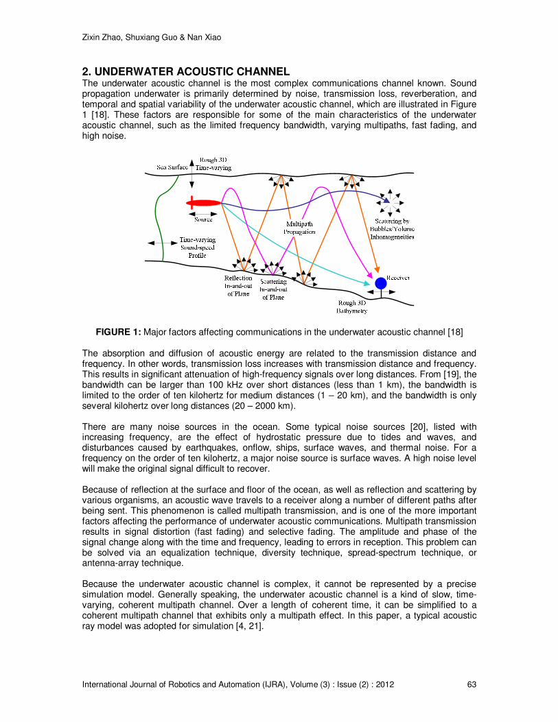
2. UNDERWATER ACOUSTIC CHANNEL The underwater acoustic channel is the most complex communications channel known. Sound propagation underwater is primarily determined by noise, transmission loss, reverberation, and temporal and spatial variability of the underwater acoustic channel, which are illustrated in Figure 1 [18]. These factors are responsible for some of the main characteristics of the underwater acoustic channel, such as the limited frequency bandwidth, varying multipaths, fast fading, and high noise.
FIGURE 1: Major factors affecting communications in the underwater acoustic channel [18]
The absorption and diffusion of acoustic energy are related to the transmission distance and frequency. In other words, transmission loss increases with transmission distance and frequency. This results in significant attenuation of high-frequency signals over long distances. From [19], the bandwidth can be larger than 100 kHz over short distances (less than 1 km), the bandwidth is limited to the order of ten kilohertz for medium distances (1 – 20 km), and the bandwidth is only several kilohertz over long distances (20 – 2000 km).
There are many noise sources in the ocean. Some typical noise sources [20], listed with increasing frequency, are the effect of hydrostatic pressure due to tides and waves, and disturbances caused by earthquakes, onflow, ships, surface waves, and thermal noise. For a frequency on the order of ten kilohertz, a major noise source is surface waves. A high noise level will make the original signal difficult to recover.
Because of reflection at the surface and floor of the ocean, as well as reflection and scattering by various organisms, an acoustic wave travels to a receiver along a number of different paths after being sent. This phenomenon is called multipath transmission, and is one of the more important factors affecting the performance of underwater acoustic communications. Multipath transmission results in signal distortion (fast fading) and selective fading. The amplitude and phase of the signal change along with the time and frequency, leading to errors in reception. This problem can be solved via an equalization technique, diversity technique, spread-spectrum technique, or antenna-array technique.
Because the underwater acoustic channel is complex, it cannot be represented by a precise simulation model. Generally speaking, the underwater acoustic channel is a kind of slow, time-varying, coherent multipath channel. Over a length of coherent time, it can be simplified to a coherent multipath channel that exhibits only a multipath effect. In this paper, a typical acoustic ray model was adopted for simulation [4, 21].
Zixin Zhao, Shuxiang Guo & Nan Xiao
International Journal of Robotics and Automation (IJRA), Volume (3) : Issue (2) : 2012 64
3. COMMUNICATIONS PROCEDURE In this section, the working principle and structure of the communications system are explained in detail, including the tamed spread-spectrum method, FHMA system, and receiving techniques.
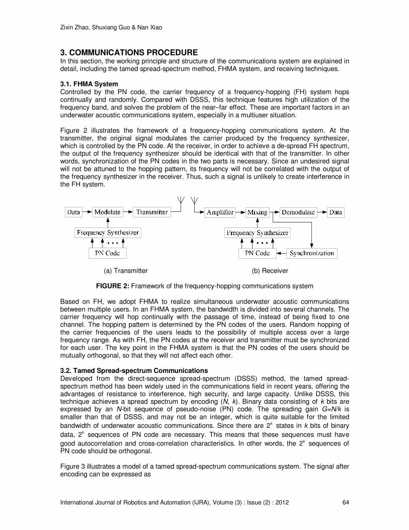
3.1. FHMA System Controlled by the PN code, the carrier frequency of a frequency-hopping (FH) system hops continually and randomly. Compared with DSSS, this technique features high utilization of the frequency band, and solves the problem of the near–far effect. These are important factors in an underwater acoustic communications system, especially in a multiuser situation. Figure 2 illustrates the framework of a frequency-hopping communications system. At the transmitter, the original signal modulates the carrier produced by the frequency synthesizer, which is controlled by the PN code. At the receiver, in order to achieve a de-spread FH spectrum, the output of the frequency synthesizer should be identical with that of the transmitter. In other words, synchronization of the PN codes in the two parts is necessary. Since an undesired signal will not be attuned to the hopping pattern, its frequency will not be correlated with the output of the frequency synthesizer in the receiver. Thus, such a signal is unlikely to create interference in the FH system.
• • •
• • •
(a) Transmitter (b) Receiver
FIGURE 2: Framework of the frequency-hopping communications system Based on FH, we adopt FHMA to realize simultaneous underwater acoustic communications between multiple users. In an FHMA system, the bandwidth is divided into several channels. The carrier frequency will hop continually with the passage of time, instead of being fixed to one channel. The hopping pattern is determined by the PN codes of the users. Random hopping of the carrier frequencies of the users leads to the possibility of multiple access over a large frequency range. As with FH, the PN codes at the receiver and transmitter must be synchronized for each user. The key point in the FHMA system is that the PN codes of the users should be mutually orthogonal, so that they will not affect each other.
3.2. Tamed Spread-spectrum Communications Developed from the direct-sequence spread-spectrum (DSSS) method, the tamed spread-spectrum method has been widely used in the communications field in recent years, offering the advantages of resistance to interference, high security, and large capacity. Unlike DSSS, this technique achieves a spread spectrum by encoding (N, k). Binary data consisting of k bits are expressed by an N-bit sequence of pseudo-noise (PN) code. The spreading gain G=N/k is smaller than that of DSSS, and may not be an integer, which is quite suitable for the limited
bandwidth of underwater acoustic communications. Since there are 2k states in k bits of binary
data, 2k sequences of PN code are necessary. This means that these sequences must have
good autocorrelation and cross-correlation characteristics. In other words, the 2k sequences of PN code should be orthogonal.
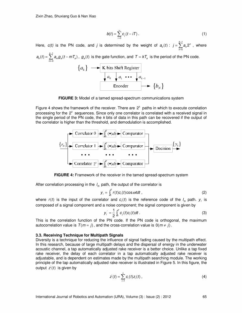
Figure 3 illustrates a model of a tamed spread-spectrum communications system. The signal after encoding can be expressed as
Zixin Zhao, Shuxiang Guo & Nan Xiao
International Journal of Robotics and Automation (IJRA), Volume (3) : Issue (2) : 2012 65
∞
=
= −∑0
( ) ( )ji
b t c t iT . (1)
Here, c(t) is the PN code, and j is determined by the weight of ( )ka t : −
=
= ∑1
0
2k
n
nn
j a , where
−
=
= −∑1
0
( ) ( )k
k m a am
a t a g t mT , ( )ag t is the gate function, and = aT kT is the period of the PN code.
{ }ka
0a
1a 1ka −
{ }Nb
• • •
FIGURE 3: Model of a tamed spread-spectrum communications system
Figure 4 shows the framework of the receiver. There are 2k paths in which to execute correlation
processing for the 2k sequences. Since only one correlator is correlated with a received signal in the single period of the PN code, the k bits of data in this path can be recovered if the output of the correlator is higher than the threshold, and demodulation is accomplished.
2k
• • •
{ }ky{ }Nr
0( )
T
dt•∫
0( )
T
dt•∫
0( )
T
dt•∫
• • • • • •
FIGURE 4: Framework of the receiver in the tamed spread-spectrum system
After correlation processing in the thl path, the output of the correlator is
ω= ∫0 ( ) ( )cosT
l ly r t c t tdt , (2)
where ( )r t is the input of the correlator and ( )lc t is the reference code of the thl path. ly is
composed of a signal component and a noise component; the signal component is given by
= ∫'
0
1( ) ( )
2
T
l j ly c t c t dt . (3)
This is the correlation function of the PN code. If the PN code is orthogonal, the maximum
autocorrelation value is =( )T m j , and the cross-correlation value is ≠0( )m j .
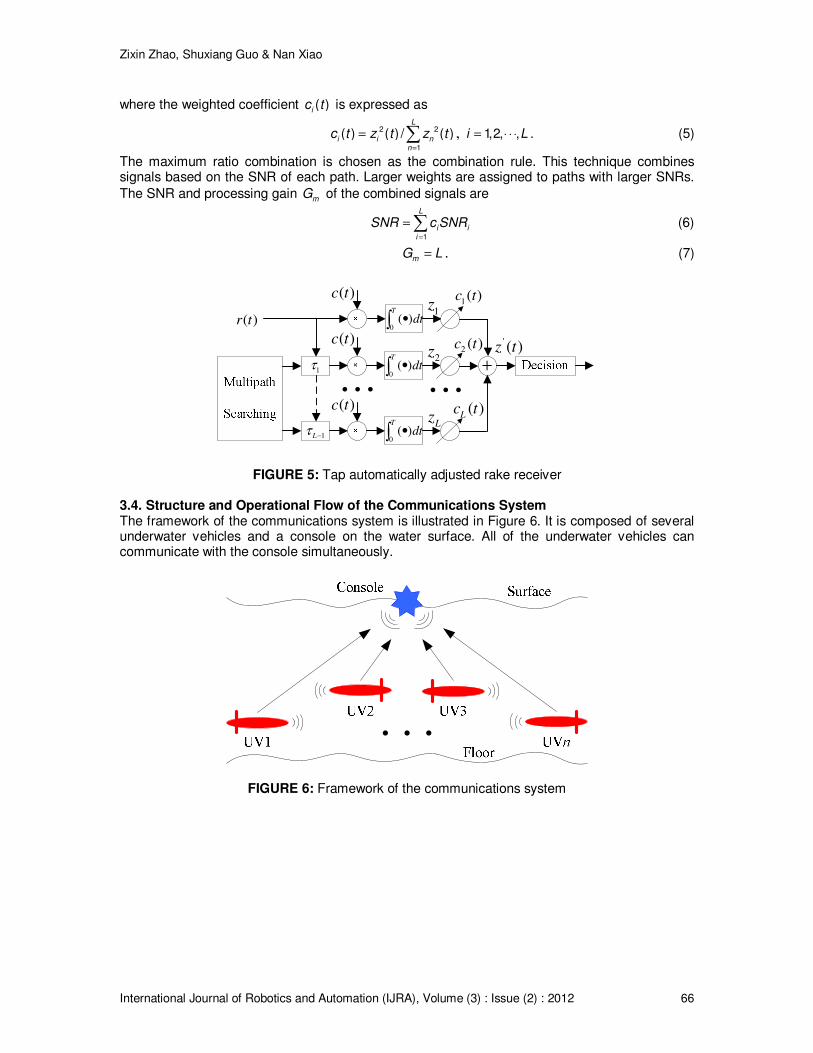
3.3. Receiving Technique for Multipath Signals Diversity is a technique for reducing the influence of signal fading caused by the multipath effect. In this research, because of large multipath delays and the dispersal of energy in the underwater acoustic channel, a tap automatically adjusted rake receiver is a better choice. Unlike a tap fixed rake receiver, the delay of each correlator in a tap automatically adjusted rake receiver is adjustable, and is dependent on estimates made by the multipath searching module. The working principle of the tap automatically adjusted rake receiver is illustrated in Figure 5. In this figure, the
output ' ( )z t is given by
=
=∑'
1
( ) ( ) ( )L
i ii
z t c t z t , (4)
Zixin Zhao, Shuxiang Guo & Nan Xiao
International Journal of Robotics and Automation (IJRA), Volume (3) : Issue (2) : 2012 66
where the weighted coefficient ( )ic t is expressed as
=
= ∑2 2
1
( ) ( ) / ( )L
i i nn
c t z t z t , = ⋅ ⋅ ⋅1,2, ,i L . (5)
The maximum ratio combination is chosen as the combination rule. This technique combines signals based on the SNR of each path. Larger weights are assigned to paths with larger SNRs.
The SNR and processing gain mG of the combined signals are
=
=∑1
L
i ii
SNR c SNR (6)
=mG L . (7)
+1τ
1Lτ −
( )r t0
( )T
dt•∫
0( )
T
dt•∫
0( )
T
dt•∫
( )c t
( )c t
( )c t
1( )c t
2( )c t
( )Lc t
1z
2z
Lz
'( )z t
• • • • • •
FIGURE 5: Tap automatically adjusted rake receiver 3.4. Structure and Operational Flow of the Communications System The framework of the communications system is illustrated in Figure 6. It is composed of several underwater vehicles and a console on the water surface. All of the underwater vehicles can communicate with the console simultaneously.
•••
FIGURE 6: Framework of the communications system
Zixin Zhao, Shuxiang Guo & Nan Xiao
International Journal of Robotics and Automation (IJRA), Volume (3) : Issue (2) : 2012 67
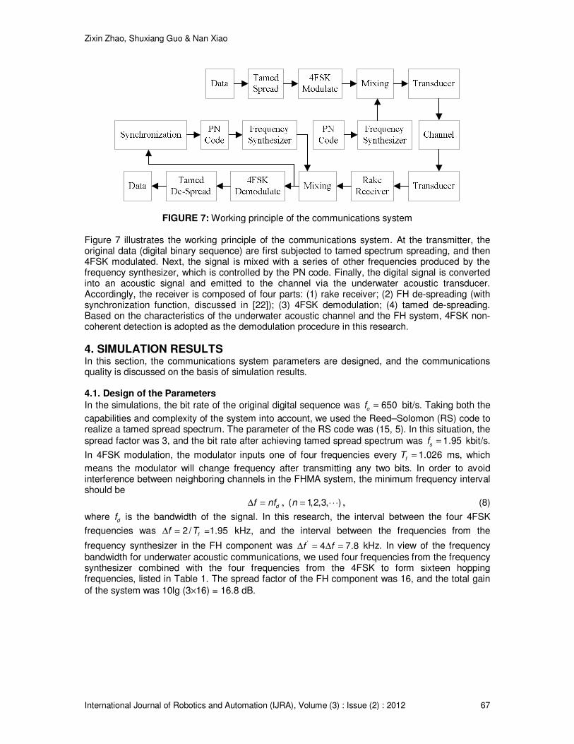
FIGURE 7: Working principle of the communications system Figure 7 illustrates the working principle of the communications system. At the transmitter, the original data (digital binary sequence) are first subjected to tamed spectrum spreading, and then 4FSK modulated. Next, the signal is mixed with a series of other frequencies produced by the frequency synthesizer, which is controlled by the PN code. Finally, the digital signal is converted into an acoustic signal and emitted to the channel via the underwater acoustic transducer. Accordingly, the receiver is composed of four parts: (1) rake receiver; (2) FH de-spreading (with synchronization function, discussed in [22]); (3) 4FSK demodulation; (4) tamed de-spreading. Based on the characteristics of the underwater acoustic channel and the FH system, 4FSK non-coherent detection is adopted as the demodulation procedure in this research.
4. SIMULATION RESULTS In this section, the communications system parameters are designed, and the communications quality is discussed on the basis of simulation results.
4.1. Design of the Parameters
In the simulations, the bit rate of the original digital sequence was = 650of bit/s. Taking both the
capabilities and complexity of the system into account, we used the Reed–Solomon (RS) code to realize a tamed spread spectrum. The parameter of the RS code was (15, 5). In this situation, the
spread factor was 3, and the bit rate after achieving tamed spread spectrum was = 1.95sf kbit/s.
In 4FSK modulation, the modulator inputs one of four frequencies every = 1.026fT ms, which
means the modulator will change frequency after transmitting any two bits. In order to avoid interference between neighboring channels in the FHMA system, the minimum frequency interval should be
∆ = df nf , = ⋅ ⋅ ⋅( 1,2,3, )n , (8)
where df is the bandwidth of the signal. In this research, the interval between the four 4FSK
frequencies was ∆ = 2/ =1.95ff T kHz, and the interval between the frequencies from the
frequency synthesizer in the FH component was ∆ = ∆ =' 4 7.8f f kHz. In view of the frequency
bandwidth for underwater acoustic communications, we used four frequencies from the frequency synthesizer combined with the four frequencies from the 4FSK to form sixteen hopping frequencies, listed in Table 1. The spread factor of the FH component was 16, and the total gain
of the system was 10lg (3×16) = 16.8 dB.
Zixin Zhao, Shuxiang Guo & Nan Xiao
International Journal of Robotics and Automation (IJRA), Volume (3) : Issue (2) : 2012 68
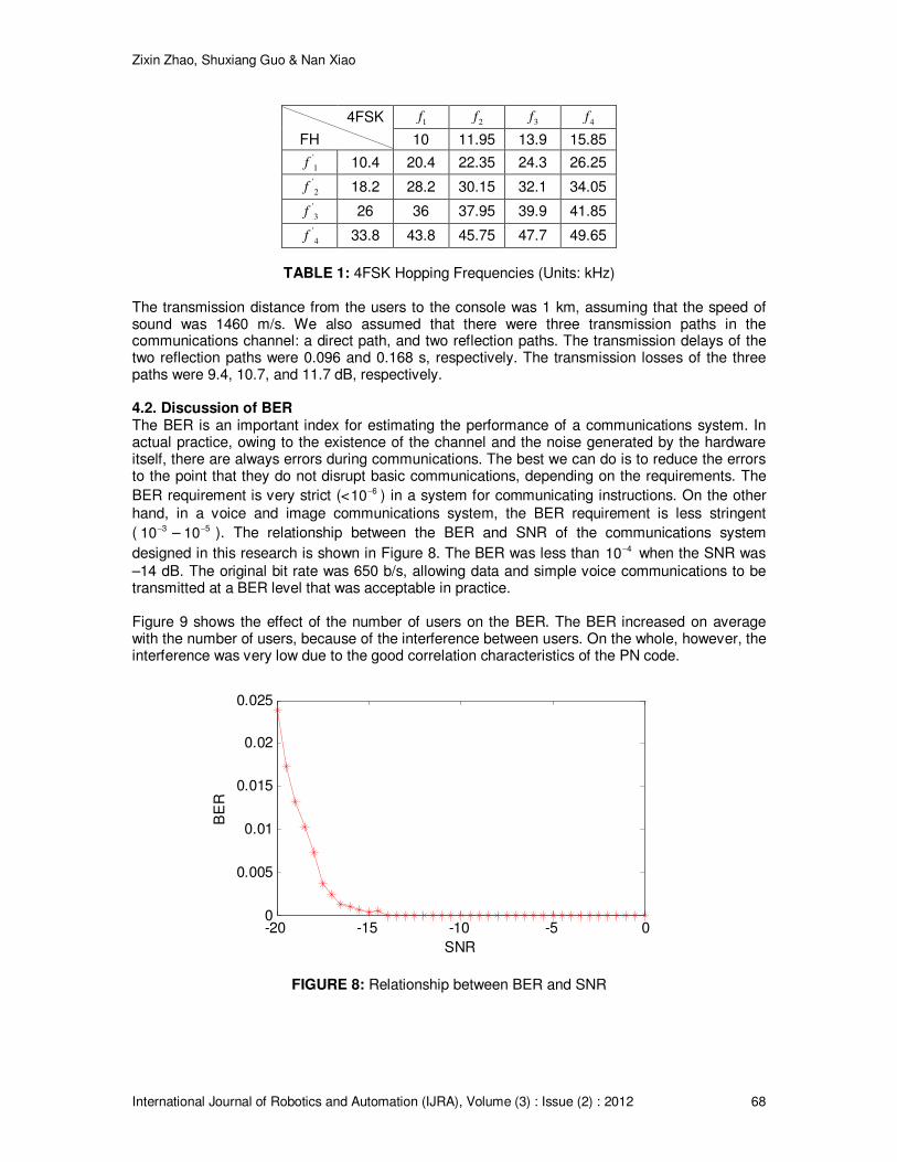
4FSK 1f
2f
3f
4f
FH 10 11.95 13.9 15.85 '
1f 10.4 20.4 22.35 24.3 26.25
'
2f 18.2 28.2 30.15 32.1 34.05
'
3f 26 36 37.95 39.9 41.85
'
4f 33.8 43.8 45.75 47.7 49.65
TABLE 1: 4FSK Hopping Frequencies (Units: kHz)
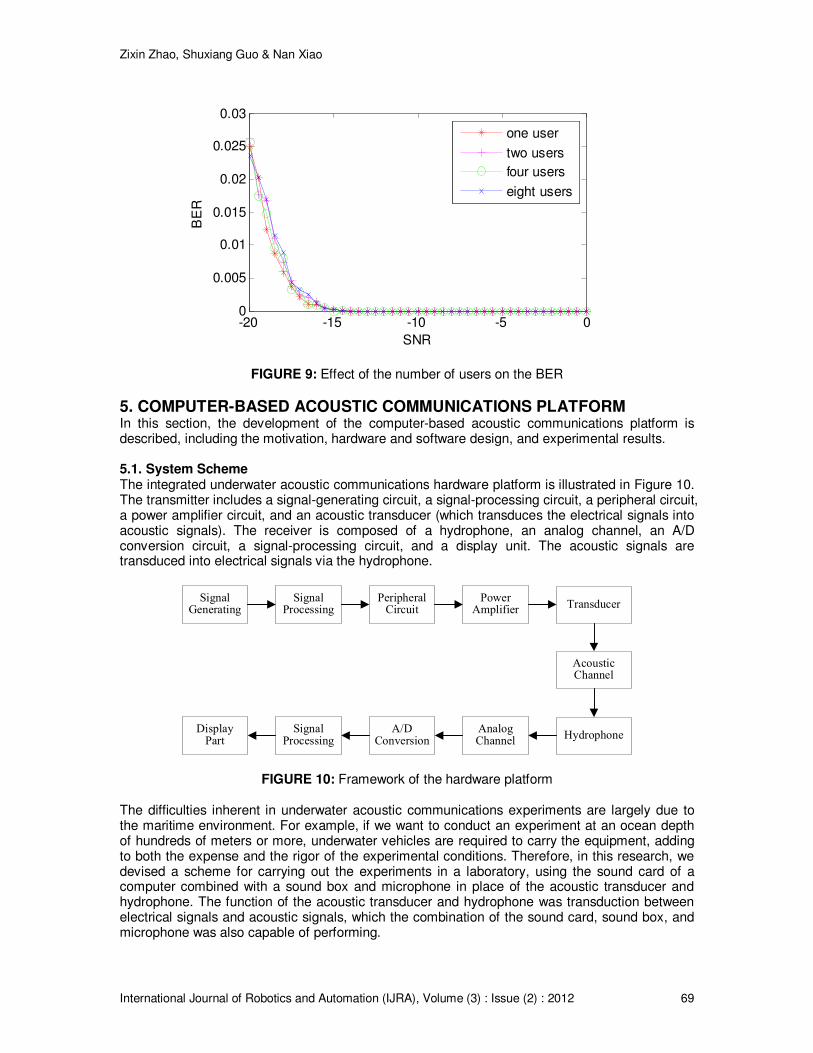
The transmission distance from the users to the console was 1 km, assuming that the speed of sound was 1460 m/s. We also assumed that there were three transmission paths in the communications channel: a direct path, and two reflection paths. The transmission delays of the two reflection paths were 0.096 and 0.168 s, respectively. The transmission losses of the three paths were 9.4, 10.7, and 11.7 dB, respectively. 4.2. Discussion of BER The BER is an important index for estimating the performance of a communications system. In actual practice, owing to the existence of the channel and the noise generated by the hardware itself, there are always errors during communications. The best we can do is to reduce the errors to the point that they do not disrupt basic communications, depending on the requirements. The
BER requirement is very strict (< −610 ) in a system for communicating instructions. On the other
hand, in a voice and image communications system, the BER requirement is less stringent
( −310 – −510 ). The relationship between the BER and SNR of the communications system
designed in this research is shown in Figure 8. The BER was less than −410 when the SNR was
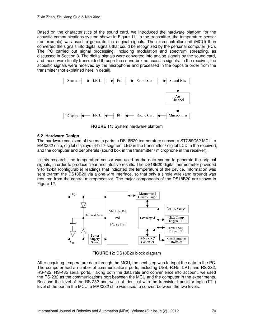
–14 dB. The original bit rate was 650 b/s, allowing data and simple voice communications to be transmitted at a BER level that was acceptable in practice. Figure 9 shows the effect of the number of users on the BER. The BER increased on average with the number of users, because of the interference between users. On the whole, however, the interference was very low due to the good correlation characteristics of the PN code.
-20 -15 -10 -5 00
0.005
0.01
0.015
0.02
0.025
SNR
BE
R
FIGURE 8: Relationship between BER and SNR
Zixin Zhao, Shuxiang Guo & Nan Xiao
International Journal of Robotics and Automation (IJRA), Volume (3) : Issue (2) : 2012 69
-20 -15 -10 -5 00
0.005
0.01
0.015
0.02
0.025
0.03
SNR
BE
R
one user
two users
four users
eight users
FIGURE 9: Effect of the number of users on the BER
5. COMPUTER-BASED ACOUSTIC COMMUNICATIONS PLATFORM In this section, the development of the computer-based acoustic communications platform is described, including the motivation, hardware and software design, and experimental results.
5.1. System Scheme The integrated underwater acoustic communications hardware platform is illustrated in Figure 10. The transmitter includes a signal-generating circuit, a signal-processing circuit, a peripheral circuit, a power amplifier circuit, and an acoustic transducer (which transduces the electrical signals into acoustic signals). The receiver is composed of a hydrophone, an analog channel, an A/D conversion circuit, a signal-processing circuit, and a display unit. The acoustic signals are transduced into electrical signals via the hydrophone.
SignalProcessing
PeripheralCircuit
PowerAmplifier
Transducer
Hydrophone
AcousticChannel
AnalogChannel
A/DConversion
DisplayPart
SignalGenerating
SignalProcessing
FIGURE 10: Framework of the hardware platform The difficulties inherent in underwater acoustic communications experiments are largely due to the maritime environment. For example, if we want to conduct an experiment at an ocean depth of hundreds of meters or more, underwater vehicles are required to carry the equipment, adding to both the expense and the rigor of the experimental conditions. Therefore, in this research, we devised a scheme for carrying out the experiments in a laboratory, using the sound card of a computer combined with a sound box and microphone in place of the acoustic transducer and hydrophone. The function of the acoustic transducer and hydrophone was transduction between electrical signals and acoustic signals, which the combination of the sound card, sound box, and microphone was also capable of performing.
Zixin Zhao, Shuxiang Guo & Nan Xiao
International Journal of Robotics and Automation (IJRA), Volume (3) : Issue (2) : 2012 70
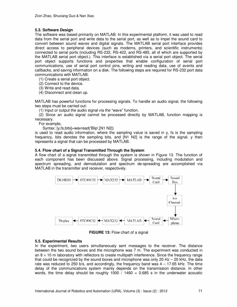
Based on the characteristics of the sound card, we introduced the hardware platform for the acoustic communications system shown in Figure 11. In the transmitter, the temperature sensor (for example) was used to generate the original signals. The microcontroller unit (MCU) then converted the signals into digital signals that could be recognized by the personal computer (PC). The PC carried out signal processing, including modulation and spectrum spreading, as discussed in Section 3. The digital signals were converted into analog signals by the sound card, and these were finally transmitted through the sound box as acoustic signals. In the receiver, the acoustic signals were received by the microphone and processed in the opposite order from the transmitter (not explained here in detail).
FIGURE 11: System hardware platform
5.2. Hardware Design The hardware consisted of five main parts: a DS18B20 temperature sensor, a STC89C52 MCU, a MAX232 chip, digital displays (4-bit 7-segment LED in the transmitter / digital LCD in the receiver), and the computer and peripherals (sound box in the transmitter / microphone in the receiver).
In this research, the temperature sensor was used as the data source to generate the original signals, in order to produce clear and intuitive results. The DS18B20 digital thermometer provided 9 to 12-bit (configurable) readings that indicated the temperature of the device. Information was sent to/from the DS18B20 via a one-wire interface, so that only a single wire (and ground) was required from the central microprocessor. The major components of the DS18B20 are shown in Figure 12.
FIGURE 12: DS18B20 block diagram After acquiring temperature data through the MCU, the next step was to input the data to the PC. The computer had a number of communications ports, including USB, RJ45, LPT, and RS-232, RS-422, RS-485 serial ports. Taking both the data rate and convenience into account, we used the RS-232 as the communications port between the MCU and the computer in the experiments. Because the level of the RS-232 port was not identical with the transistor-transistor logic (TTL) level of the port in the MCU, a MAX232 chip was used to convert between the two levels.
Zixin Zhao, Shuxiang Guo & Nan Xiao
International Journal of Robotics and Automation (IJRA), Volume (3) : Issue (2) : 2012 71
5.3. Software Design The software was based primarily on MATLAB. In this experimental platform, it was used to read data from the serial port and write data to the serial port, as well as to impel the sound card to convert between sound waves and digital signals. The MATLAB serial port interface provides direct access to peripheral devices (such as modems, printers, and scientific instruments) connected to serial ports (including RS-232, RS-422, and RS-485, all of which are supported by the MATLAB serial port object.). This interface is established via a serial port object. The serial port object supports functions and properties that enable configuration of serial port communications, use of serial port control pins, writing and reading data, use of events and callbacks, and saving information on a disk. The following steps are required for RS-232 port data communications with MATLAB:
(1) Create a serial port object. (2) Connect to the device. (3) Write and read data. (4) Disconnect and clean up.
MATLAB has powerful functions for processing signals. To handle an audio signal, the following two steps must be carried out:
(1) Input or output the audio signal via the “wave” function. (2) Since an audio signal cannot be processed directly by MATLAB, function mapping is
necessary. For example,
Syntax: [y,fs,bits]=wavread('Blip',[N1 N2]) is used to read audio information, where the sampling value is saved in y, fs is the sampling frequency, bits denotes the sampling bits, and [N1 N2] is the range of the signal. y then represents a signal that can be processed by MATLAB.
5.4. Flow chart of a Signal Transmitted Through the System A flow chart of a signal transmitted through the system is shown in Figure 13. The function of each component has been discussed above. Signal processing, including modulation and spectrum spreading, and demodulation and spectrum de-spreading are accomplished via MATLAB in the transmitter and receiver, respectively.
FIGURE 13: Flow chart of a signal 5.5. Experimental Results In the experiment, two users simultaneously sent messages to the receiver. The distance between the two sound boxes and the microphone was 7 m. The experiment was conducted in
an 8 × 10 m laboratory with reflectors to create multipath interference. Since the frequency range that could be recognized by the sound boxes and microphone was only 20 Hz – 20 kHz, the data rate was reduced to 250 b/s, and accordingly, the frequency band was 4 – 17.65 kHz. The time delay of the communications system mainly depends on the transmission distance. In other words, the time delay should be roughly 1000 / 1460 = 0.685 s in the underwater acoustic
Zixin Zhao, Shuxiang Guo & Nan Xiao
International Journal of Robotics and Automation (IJRA), Volume (3) : Issue (2) : 2012 72
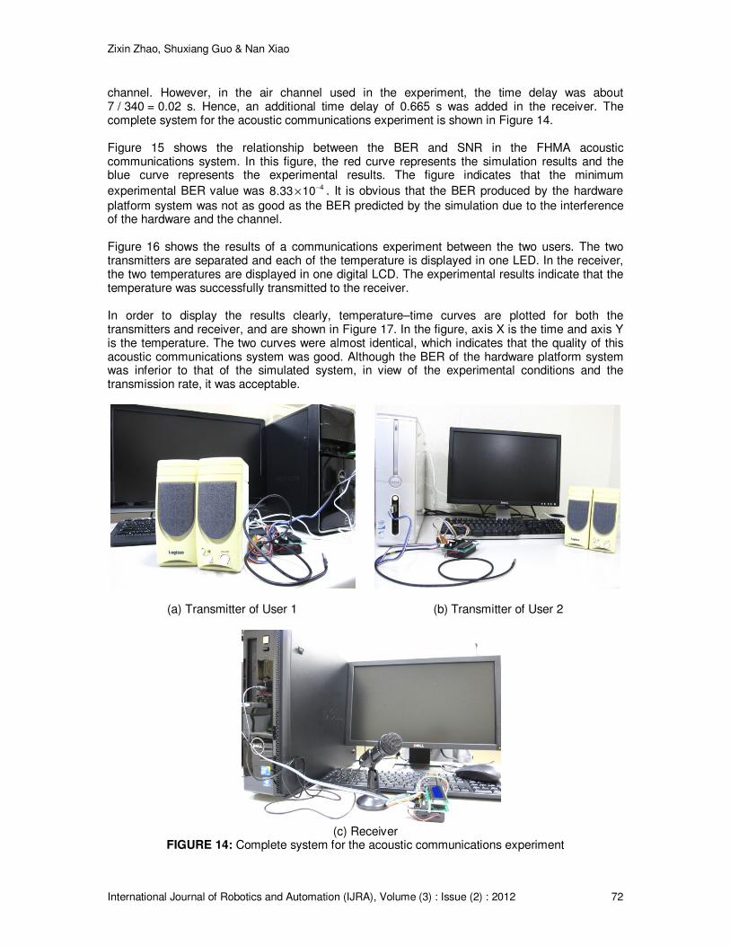
channel. However, in the air channel used in the experiment, the time delay was about 7 / 340 = 0.02 s. Hence, an additional time delay of 0.665 s was added in the receiver. The complete system for the acoustic communications experiment is shown in Figure 14.
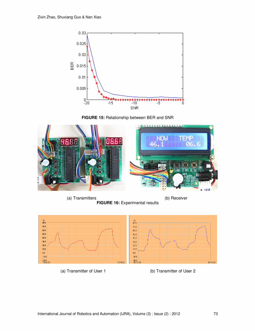
Figure 15 shows the relationship between the BER and SNR in the FHMA acoustic communications system. In this figure, the red curve represents the simulation results and the blue curve represents the experimental results. The figure indicates that the minimum
experimental BER value was −
×48.33 10 . It is obvious that the BER produced by the hardware
platform system was not as good as the BER predicted by the simulation due to the interference of the hardware and the channel.
Figure 16 shows the results of a communications experiment between the two users. The two transmitters are separated and each of the temperature is displayed in one LED. In the receiver, the two temperatures are displayed in one digital LCD. The experimental results indicate that the temperature was successfully transmitted to the receiver.
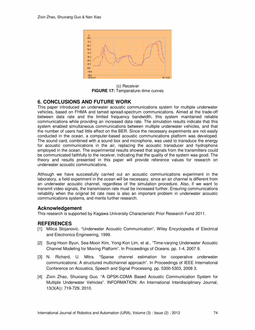
In order to display the results clearly, temperature–time curves are plotted for both the transmitters and receiver, and are shown in Figure 17. In the figure, axis X is the time and axis Y is the temperature. The two curves were almost identical, which indicates that the quality of this acoustic communications system was good. Although the BER of the hardware platform system was inferior to that of the simulated system, in view of the experimental conditions and the transmission rate, it was acceptable.
(a) Transmitter of User 1 (b) Transmitter of User 2
(c) Receiver
FIGURE 14: Complete system for the acoustic communications experiment
Zixin Zhao, Shuxiang Guo & Nan Xiao
International Journal of Robotics and Automation (IJRA), Volume (3) : Issue (2) : 2012 73
FIGURE 15: Relationship between BER and SNR
(a) Transmitters (b) Receiver FIGURE 16: Experimental results
(a) Transmitter of User 1 (b) Transmitter of User 2
Zixin Zhao, Shuxiang Guo & Nan Xiao
International Journal of Robotics and Automation (IJRA), Volume (3) : Issue (2) : 2012 74
(c) Receiver FIGURE 17: Temperature–time curves
6. CONCLUSIONS AND FUTURE WORK This paper introduced an underwater acoustic communications system for multiple underwater vehicles, based on FHMA and tamed spread-spectrum communications. Aimed at the trade-off between data rate and the limited frequency bandwidth, this system maintained reliable communications while providing an increased data rate. The simulation results indicate that this system enabled simultaneous communications between multiple underwater vehicles, and that the number of users had little effect on the BER. Since the necessary experiments are not easily conducted in the ocean, a computer-based acoustic communications platform was developed. The sound card, combined with a sound box and microphone, was used to transduce the energy for acoustic communications in the air, replacing the acoustic transducer and hydrophone employed in the ocean. The experimental results showed that signals from the transmitters could be communicated faithfully to the receiver, indicating that the quality of the system was good. The theory and results presented in this paper will provide reference values for research on underwater acoustic communications.
Although we have successfully carried out an acoustic communications experiment in the laboratory, a field experiment in the ocean will be necessary, since an air channel is different from an underwater acoustic channel, regardless of the simulation procedure. Also, if we want to transmit video signals, the transmission rate must be increased further. Ensuring communications reliability when the original bit rate rises is also an important problem in underwater acoustic communications systems, and merits further research.
Acknowledgement This research is supported by Kagawa University Characteristic Prior Research Fund 2011.
REFERENCES [1] Milica Stojanovic. “Underwater Acoustic Communication”, Wiley Encyclopedia of Electrical
and Electronics Engineering, 1999.
[2] Sung-Hoon Byun, Sea-Moon Kim, Yong-Kon Lim, et al.. “Time-varying Underwater Acoustic
Channel Modeling for Moving Platform”. In Proceedings of Oceans. pp. 1-4, 2007 9.
[3] N. Richard, U. Mitra. “Sparse channel estimation for cooperative underwater
communications: A structured multichannel approach”. In Proceedings of IEEE International
Conference on Acoustics, Speech and Signal Processing. pp. 5300-5303, 2008 3.
[4] Zixin Zhao, Shuxiang Guo. “A QPSK-CDMA Based Acoustic Communication System for
Multiple Underwater Vehicles”. INFORMATION: An International Interdisciplinary Journal,
13(3(A)): 719-729, 2010.
Zixin Zhao, Shuxiang Guo & Nan Xiao
International Journal of Robotics and Automation (IJRA), Volume (3) : Issue (2) : 2012 75
[5] S. Roy, T. Duman, L. Ghazikhanian, et al.. “Enhanced Underwater Acoustic Communication
Performance Using Space-Time Coding and Processing”. In Proceedings of MTTS/IEEE
TECHNO-OCEAN, OCEANS. pp. 26-33, 2004 11.
[6] Aijun Song, M. Badiey. “Generalized Equalization for Underwater Acoustic Communications”.
In Proceedings of MTS/IEEE OCEANS. pp. 1522-1527, 2005 9.
[7] Han Jung-Woo, Ju Hyung-Jun, Kim Ki-Man, et al.. “A Study on the Cooperative Diversity
Technique with Amplify and Forward for Underwater Wireless Communication”. In
Proceedings of MTS/IEEE Kobe Techno-Ocean, OCEANS. pp. 1-3, 2008 4.
[8] Kun-Chou Lee, Lan-Ting Wang, Jyun-Gu Ou. “Underwater Acoustic Imaging by Diversity
Techniques”. In Proceedings of Oceans. pp. 1-3, 2007 9.
[9] Trubuil Joel, Goalic Andre, Beuzelin Nicolas. “A LOW BIT-RATE SPEECH UNDERWATER
ACOUSTIC PHONE USING CHANNEL CODING FOR QUALITY IMPROVEMENT”. In
Proceedings of IEEE Military Communications Conference. pp. 1-7, 2007 10.
[10] A. Goalie, J. Trubuil, N. Beuzelin. “Channel Coding for Underwater Acoustic Communication
System”. In Proceedings of OCEANS. pp. 1-4, 2006 9.
[11] Shuxiang Guo, Zixin Zhao. “An Acoustic Communication System for Multiple Underwater
Vehicles Based on DS-CDMA”. In Proceedings of IEEE International Conference on
Information and Automation. pp. 318-323, 2009 6.
[12] Chengbing He, Jianguo Huang. “Underwater Acoustic Spread Spectrum Communication
Based on M Family N group Parallel Transmission”. In Proceedings of Asia Pacific OCEANS.
pp. 1-4, 2007 5.
[13] Xiao-yan Wang, Zhi-feng Zhu, Shi-liang Fang. “Noncooperative Detection and Parameter
Estimation of Underwater Acoustic DSSS-BPSK Signal”. In Proceedings of 14th International
Conference on Mechatronics and Machine Vision in Practice. pp. 52-56, 2007 12.
[14] Yang, T.C., Wen-Bin Yang. “Low signal-to-noise-ratio underwater acoustic communications
using direct-sequence spread-spectrum signals”. In Proceedings of Europe OCEANS. pp. 1-
6, 2007 6.
[15] Sung-Jun Hwang, Schniter, P.. “Efficient Multicarrier Communication for Highly Spread
Underwater Acoustic Channels”. IEEE Journal on Selected Areas in Communications, 26(9):
1674-1683, 2008.
[16] Roy, S., Duman, T.M., McDonald, V., Proakis, J.G.. “High-Rate Communication for
Underwater Acoustic Channels Using Multiple Transmitters and Space–Time Coding:
Receiver Structures and Experimental Results”. IEEE Journal of Oceanic Engineering, 32(3):
663-688, 2007.
[17] Stojanovic, M., Freitag, L.. “Multichannel Detection for Wideband Underwater Acoustic
CDMA Communications”. IEEE Journal of Oceanic Engineering, 31(3): 685-695, 2006.
[18] Kurtulus BEKTAS. “FULL-DUPLEX UNDERWATER NETWORKING USING CDMA”. NAVAL
POSTGRADUATE SCHOOL, MONTEREY, CALIFORNIA, USA, 2004.
[19] R. J. Vaccaro. “The Past, Present, and Future of Underwater Acoustic Processing”. IEEE
SIGNAL PROCESSING MAGAZINE, pp. 21-51, 1998 7.
Zixin Zhao, Shuxiang Guo & Nan Xiao
International Journal of Robotics and Automation (IJRA), Volume (3) : Issue (2) : 2012 76
[20] Robert J. Urick. “Principles of Underwater Sound (3rd Edition)”, Peninsula Pub., 1996.
[21] John G. Proakis. “Digital Communications (4th Edition)”, MeGraw-Hill Science, 2000.
[22] Zixin Zhao, Shuxiang Guo. “Design of an Acoustic Communication System Based on FHMA
for Multiple Underwater Vehicles”. Journal of Wireless Engineering and Technology, 1(1):
27-35, 2010.