Embed Size (px)
Citation preview

Development of an Intelligent Proximity Detection System for Continuous Mining Machines
Christopher Jobes, PhD, PEMechanical Engineer
Jacob Carr, MSSafety Engineer
Electrical & Mechanical Systems Safety
Proximity Warning Systems for Mining EquipmentCharleston, WVSeptember 15, 2010

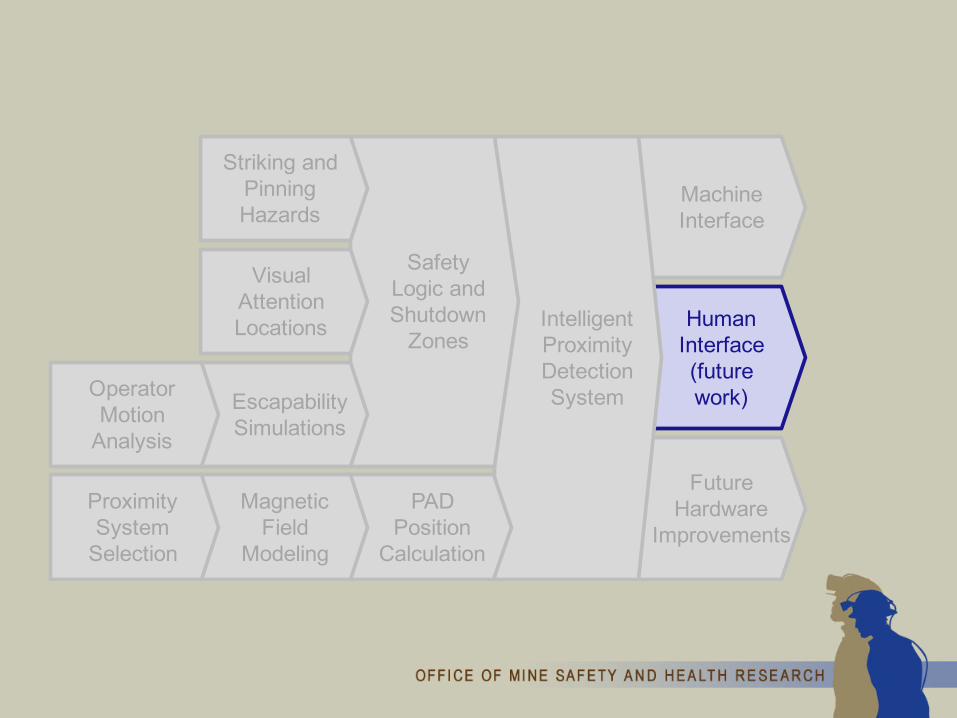
Presentation Outline
Future Hardware
Improvements
Human Interface(future work)
Machine Interface
Intelligent Proximity Detection System
Safety Logic and Shutdown
Zones
PAD Position
Calculation
Visual Attention Locations
Magnetic Field
Modeling
Operator Motion
Analysis
EscapabilitySimulations
Proximity System
Selection
Striking and Pinning Hazards

Striking and Pinning Hazards• Operator injuries involving continuous mining
machines averaged 248 annually for the past 5 years• Contributing Factor - Complex Work Environment
o Radio remote control allows freedom of movemento Large moving equipment in confined environmento Dynamic work area

Striking and Pinning HazardsWeight: >100,000 lbMax Speed: ~85 fpmPivot Rate: ~19°/s6 fps at corner of rear
bumper

Future Hardware
Improvements
Human Interface(future work)
Machine Interface
Intelligent Proximity Detection System
Safety Logic and Shutdown
Zones
PAD Position
Calculation
Visual Attention Locations
Magnetic Field
Modeling
Operator Motion
Analysis
EscapabilitySimulations
Proximity System
Selection
Striking and Pinning Hazards
Operator Visual Attention Locations (VALs)
Objective - to analyze the effect of operator cues on work positions:
• Structured interviews• Ranking to evaluate cue significance• Computer simulation to evaluate operator view
by position• Assessment of operator view in multiple
postures

Operator Visual Attention Locations (VALs)Typical Positions During Complete Cutting Cycle
Operator Position1 11%2 13%3 9%4 16%5 15%6 17%7 14%8 2%9 2%
10 1%

Operator Visual Attention Locations (VALs)Visual Areas Defined as a Matrix of Points

Operator Visual Attention Locations (VALs)Simulated Scanning to Determine Visibility
• Visibility - best positions are closer to the machine
• Safety - best positions are farther from mining equipment

Future Hardware
Improvements
Human Interface(future work)
Machine Interface
Intelligent Proximity Detection System
Safety Logic and Shutdown
Zones
PAD Position
Calculation
Visual Attention Locations
Magnetic Field
Modeling
Operator Motion
Analysis
EscapabilitySimulations
Proximity System
Selection
Striking and Pinning Hazards

Operator Motion Analysis ResearchAll Position Related Injuries 2004 - 2008
Position Related Accidents by ZoneA) Tail Left 3%B) Tail Right 11%C) Center Right 6%D) Center Left 2%E) Drum Left 1%F) Drum Right 2%G) Rib Right 12%H) Rib Left 2%I) Unknown (Supported Roof) 45%J) Unknown (Unsupported Roof) 1%K) Front 1%L) Rear 14%

Operator Motion Analysis ResearchMotion Data Capture
• 3 postures • 3 facing directions• 8 escape directions

Future Hardware
Improvements
Human Interface(future work)
Machine Interface
Intelligent Proximity Detection System
Safety Logic and Shutdown
Zones
PAD Position
Calculation
Visual Attention Locations
Magnetic Field
Modeling
Operator Motion
Analysis
EscapabilitySimulations
Proximity System
Selection
Striking and Pinning Hazards

Operator Escapability Computer SimulationsSimulation of Machine Movement with Motion Data

Operator Escapability Computer SimulationsSimulation Results
• Initial assumption - CM speed would be the most significant factor in struck-by accidents
• Finding - Statistical analysis indicated locationwas the most important factor
• Data showed that a position farther than 3 ft from a moving machine part could significantly reduce the likelihood of an operator being struck by the CM

Future Hardware
Improvements
Human Interface(future work)
Machine Interface
Intelligent Proximity Detection System
Safety Logic and Shutdown
Zones
PAD Position
Calculation
Visual Attention Locations
Magnetic Field
Modeling
Operator Motion
Analysis
EscapabilitySimulations
Proximity System
Selection
Striking and Pinning Hazards

Proximity Detection Method Selection
• Systems relying on GPS or vision were either not possible or practical
• NIOSH has previously developed an active proximity warning system called HASARD (Hazardous Area Signaling and Ranging Device) for warning workers as they approach known dangerous areas around heavy mining equipment and other dangerous work zones
• Commercially available proximity detection hardware based on this research was selected in conjunction with a modified controller to yield the information needed for the Intelligent Proximity Detection System

Current Proximity Detection Technology
Ferrite-Cored Magnetic Field
Generator
Personal Alarm Device
(PAD)
Increasing Magnetic Flux Density
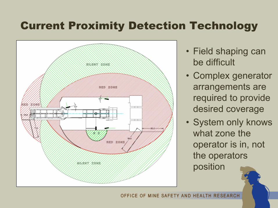
Current Proximity Detection Technology
• Field shaping can be difficult
• Complex generator arrangements are required to provide desired coverage
• System only knows what zone the operator is in, not the operators position

Future Hardware
Improvements
Human Interface(future work)
Machine Interface
Intelligent Proximity Detection System
Safety Logic and Shutdown
Zones
PAD Position
Calculation
Visual Attention Locations
Magnetic Field
Modeling
Operator Motion
Analysis
EscapabilitySimulations
Proximity System
Selection
Striking and Pinning Hazards

Magnetic Field Modeling( ) ba +⋅⋅= θρ 2cos

Magnetic Field Modeling

Future Hardware
Improvements
Human Interface(future work)
Machine Interface
Intelligent Proximity Detection System
Safety Logic and Shutdown
Zones
PAD Position
Calculation
Visual Attention Locations
Magnetic Field
Modeling
Operator Motion
Analysis
EscapabilitySimulations
Proximity System
Selection
Striking and Pinning Hazards

Triangulation Techniques
• Determining the exact location of the PAD isn’t easy due to the magnetic field shapes
• Two novel triangulation techniques were developed to deal with the irregularities in the field shapes

Triangulation TechniquesThree Generators Yielding 2D Position
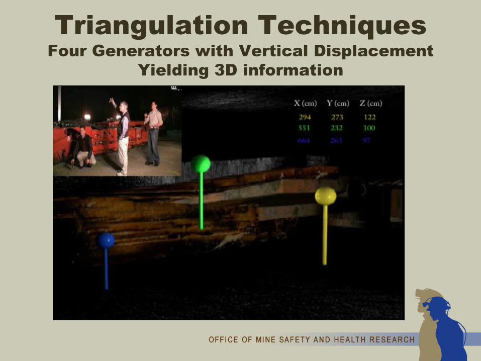
Triangulation TechniquesFour Generators with Vertical Displacement
Yielding 3D information
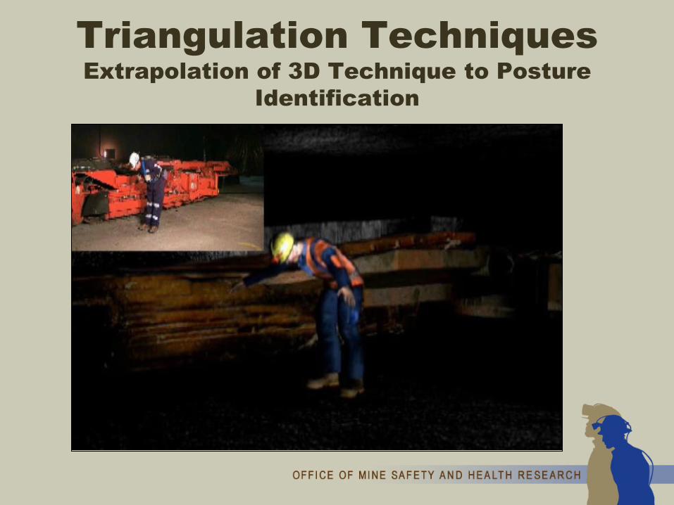
Triangulation TechniquesExtrapolation of 3D Technique to Posture
Identification

Future Hardware
Improvements
Human Interface(future work)
Machine Interface
Intelligent Proximity Detection System
Safety Logic and Shutdown
Zones
PAD Position
Calculation
Visual Attention Locations
Magnetic Field
Modeling
Operator Motion
Analysis
EscapabilitySimulations
Proximity System
Selection
Striking and Pinning Hazards

Intelligent Proximity Detection
• Installed and tested on a Joy 14CM
• The intelligent proximity detection system determines triangulated position of miners near the machine

Intelligent Proximity Detection
• Situation-specific alarms are issued
• Specific machine functions are blocked
• The warning and shutdown zones are dynamic and programmable

Future Hardware
Improvements
Human Interface(future work)
Machine Interface
Intelligent Proximity Detection System
Safety Logic and Shutdown
Zones
PAD Position
Calculation
Visual Attention Locations
Magnetic Field
Modeling
Operator Motion
Analysis
EscapabilitySimulations
Proximity System
Selection
Striking and Pinning Hazards

Machine Control Interface:Normal Operation
Remote Control DemuxOperator
input
Left track forward
Right track reverse
Conveyor left
Conveyor right..
17 functions in total
.
.
Actuator Controls

Machine Control Interface:Intelligent Proximity Detection
Remote Control DemuxOperator
input..
Left track forward
Right track reverse
Conveyor left
Conveyor right..
17 functions in total
Actuator Controls
.
...
Relays
Onboard Controller
Relay Controls

Machine Control Interface:Prototype Hardware as Installed
• Onboard controller runs intelligent proximity software
• Proximity relays block machine functions
• Visual warning system relays will control LED warning lights
• Wireless link communicates data to a Host PC

Machine Control Interface:Hardware as Installed
• The Host PC is used for programming and viewing data in real-time
• ALL system calculations are performed by the onboard controller

Machine Control Interface:Software
• Algorithms tested first in simulation then installed on the Joy 14CM
• Real-time display allows for on-the-fly testing and modification

Testing System as Installed on Joy 14CM
• Data collected with PAD on a 1-meter grid around the CM
• Various PAD heights
• Various machine poses

Testing System as Installed on Joy 14CM
• Triangulation requires signal from at least 2 generators
• Generators are concentrated near the tail, resulting in good accuracy in that area

Testing System as Installed on Joy 14CM
Proximity system should perform properly regardless of:• Pad elevation
– Low (16”)– Mid (44”)– High (48”)
• Conveyor elevation– Down– Up
• Conveyor swing– Left– Center– Right
Testing System as Installed on Joy 14CM
Proximity system should perform properly regardless of:• Cutter head position
– Down– Up
• Trailing cable– On floor– Draped over tail
• Hydraulic pump / conveyor / cutter motors– On– Off
Testing System as Installed on Joy 14CM
Proximity system should perform properly regardless of:• Presence of other metallic objects
– Shuttle cars– Mine infrastructure
• Interference from RF signals– Communication

Testing System as Installed on Joy 14CM
• Real-time position tracking
• Dynamic safety zones

Testing System as Installed on Joy 14CM
• Forward tram is allowed
• Reverse tram is not allowed within 3 feet

Testing System as Installed on Joy 14CM
• Tail swing left is allowed
• Tail swing right is not allowed within 3 feet

Testing System as Installed on Joy 14CM
• Pivot right is allowed
• Pivot left is not allowed within 3 feet
Future Hardware
Improvements
Human Interface(future work)
Machine Interface
Intelligent Proximity Detection System
Safety Logic and Shutdown
Zones
PAD Position
Calculation
Visual Attention Locations
Magnetic Field
Modeling
Operator Motion
Analysis
EscapabilitySimulations
Proximity System
Selection
Striking and Pinning Hazards

Human Interface:Alarm System
• Several methods of providing alarms (audible and visual) to the operator will be tested– NIOSH-developed LED Visual
Warning System
• The alarms need to clearly convey meaning to the operator – for example:– Person detected near left rib– Reverse tram disabled

Future Hardware
Improvements
Human Interface(future work)
Machine Interface
Intelligent Proximity Detection System
Safety Logic and Shutdown
Zones
PAD Position
Calculation
Visual Attention Locations
Magnetic Field
Modeling
Operator Motion
Analysis
EscapabilitySimulations
Proximity System
Selection
Striking and Pinning Hazards

Current Four-Generator System

Future Work:Expansion of System to Six Generators

Future Work:Further Laboratory Evaluation
• Future tests will include:– Triangulation accuracy– System reliability– Simulated mining tasks
• We are exploring partnerships to introduce this improvement to proximity detection technology to the mines
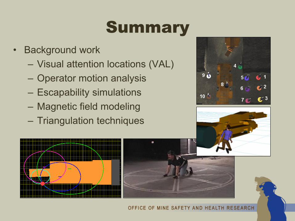
Summary• Background work
– Visual attention locations (VAL)– Operator motion analysis– Escapability simulations– Magnetic field modeling– Triangulation techniques

Summary• Intelligent proximity detection system
– Real-time tracking (2D or 3D position) of multiple people
– Programmable, dynamic warning and shutdown zones

Thank you for your attention

Disclaimer: The findings and conclusions in this presentation are those of the authors and do not necessarily represent the views of NIOSH. Mention of company names or products does not constitute endorsement by the Centers for Disease Control and Prevention

Presented by: Christopher Jobes, PhD, PEJacob Carr, MS
Contact info: [email protected](412) [email protected](412) 386-6877
The Office of Mine Safety and Health Research is a division of the National Institute for Occupational Safety and Health (NIOSH) www.cdc.gov/niosh/mining
NIOSH is a division of the Centers for Disease Control and Prevention within the Department of Health and Human Services www.hhs.gov


![dangerous ['deind ʒ ərəs] Don’t _______! It’s dangerous!](https://img.pdfslide.net/doc/110x75/56649d1b5503460f949f0dc4/dangerous-deind-rs-dont-its-dangerous.jpg)