Embed Size (px)
Citation preview

Country Papers II
Development of drainage in Turkey over the last 25 years and its prospects for the future S. Sener Village Affairs Research Institute, Menemen, Izmir, Turkey
1 Physiography and land use
The total area of Turkey is 780 580 km2 of which 23 500 km2 is situated in Europe. The land under cultivation at present is 27 699 O10 ha. Pasture and grazing land covers 21 745 690 ha and forests 15 135 090 ha. An account of the land use pattern in Turkey is given in Table 1.
Table 1 Land use pattern in Turkey (TOPRAKSU 1978)
Type of land use Area
ha Yo
I Cultivated agricultural land 22 607 340 2 990 880 2 100 790
Dryland farming Irrigated area Vineyard and orchards
27 699 O1 O 2 Pasture and grazing land 2 1 745 690 3 Forests and shrubs
Forests 15 135090 Bushes and shrubs 8 333 380
23 468 470 4 Settlements 569 400 5 Unproductive land 3212 I80 6 Lakes 1 102390
77 797 140
35.6 28.0
30.2 0.7 4.1 I .4
100.0 -
Turkey has a population of 50 million. About 55 per cent of the population lives in rural areas and 61 per cent of the labour is employed in agriculture. Physiographically, Turkey can be divided into four regions with different characteristics.
Coastal lands In the north and in the south high mountain ranges stretch parallel to the coast, form- ing small terraces and bottom lands with the exception of some large alluvial deltas formed by the rivers. The alluvial soils comprise the largest and most important group
236

Country Papers II
of arable soils. Elevations vary from sea level to 150 m. Salinity and drainage constitute the main problems in the coastal lands.
Central Anatolian Plateau A high plateau located in the central part of the country, is divided by rivers into many irregular areas. This region has different landscapes, such as mountains, bench lands, closed basins and some narrow alluvial plains. The elevation varies from 800 to 1500 m. Most of this plateau is suited for agricultural use, especially for grain pro- duction.
Mountain lands This area shows a very rough relief and has steep slopes with elevations generally between 1500 and 4000 m. Vegetal cover changes from weedy, mostly barren rocky surface to dense forests.
Basin lands of Thrace The whole European part of the country except the Istrance Mountain Ranges consists of basin lands. It is an open and divided plain having an undulating topography in the center. Most of these basin lands are suitable for agriculture.
2 Climate and rainfall
Turkey has in general a semi-arid climate with extreme temperatures. Almost the whole Anatolian plateau has hot, dry, dusty summers and cold, windy, damp winters, but in the Eastern Anatolian region the summers are cool and short and the winters are severe and long. The Mediterranean climate with short, wet winters and long, warm, sunny summers, prevails in the southern and western part of the country.
The average annual rainfall is 670 mm, but varies from a minimum of 220 mm to a maximum of 2420 mm. There is a great variation in space and time. Meteorological data show that over 90% of Turkey has not enough soil water during the crop growing season, and for good agricultural production irrigation is essential in most parts of the country.
3 Drainage and salinity problems with regard to soil conditions
The soils of Turkey vary considerably in fertility. The soils of the Central Anatolian Plateau reflect the semi-arid steppe condition of the region. Here low rainfall coupled with sparse plant cover of short grasses has resulted in the formation of limestone as parent material. The character of the terrain handicaps the development of deep natural soils in this highland area and most of the soils are thin and easily erodable. Overgrazing and deforestation of the sloping lands have led to an intensification of the soil erosion problem.
237

Country Papers 11
More productive soils, comprising of clay and lime underlain by deep sand-silt and clay strata are found in the coastal and lowland regions of Turkey. These areas cover nearly one-seventh of the total cropland of Turkey. The capabilities of these alluvial soils for crop production range from low, due to frequent flooding or low natural fertility, to very high. They have greater potential for increased agricultural production than any other group of soils.
According to the General Improved Soil Map of Turkey which is prepared by TO- PRAKSU (1966-1971), 2 775 110 ha of cultivated land has drainage problems, which is 3.6 per cent of the total area of 77 797 140 ha.
On the other hand 1 518 720 ha of cultivated land (2.0% of the total area) has salinity or alkalinity (sodium) problems. These soil types are classified into five cate- gories according to the extent of the problem: Light saline soils Saline soils Alkali (sodic) soils Light saline and alkali soils: O . 150.35% soluble salts, ESP > 15; Saline and alkali soils
: 0.15-0.35% soluble salts, ESP < 15; : Soluble salts > 0.35%, ESP < 15; : Soluble salts < O . 15%, ESP > 15;
: Soluble salts >0.35%, ESP > 15.
Dominant salts accumulated in the soils are chlorides (NaCI, CaCl,, MgCl,), sulphates (Na, SO4, MgSO,), nitrates (NaNO,, KNO,), carbonates and bicarbonates (Na, CO3, NaHCO,), and boron salts in certain areas. Sodium salts occur most frequently, but calcium and magnesium compounds are common too.
4 The main areas where surface or subsurface drainage has been installed in the past 25 years
Although very simple individual surface and subsurface drainage systems have been found in Anatolia since Roman and Ottoman time, only extensive and planned work on this subject has been started since 1950 on a project basis. In those years'and a few years ago, some big irrigation projects such as Seyhan, Cumra, Menemen and Alpu were completed and irrigated agriculture was started in these rather flat alluvial and hydromorfic alluvial soils. As soon as irrigation started crop yields doubled. But the following years irrigated agriculture brought new problems to the farmers such as high watertables, salinity and alkalinity. On the other hand new dams and irrigation schemes came under construction whereby sufficient drainage had to be provided.
In the 1960's an intensive land reclamation and drainage program was initiated by the government with the assistance of international organizations, such as the Inter- national Development Agency (IDA), European Investment Bank (EIB) and Interna- tional Bank for Reconstruction and Development (IBRD). As a result of this pro- gramme surface and subsurface drainage works have been started in 21 big irrigation projects (Table 2 and Figure 1). Surface and subsurface drainage works are mostly completed in these projects. However, in the coastal plains the lowlands below 2.00 m elevation which require pumping for drainwater disposal are for economic reason still in a future drainage project phase.
238

Table 2 The most important land development and drainage projects in the last 25 years in Turkey
Name of the project Total area Land levelling Subsurface drainage Surface Land Land (ha) drainage reclama- consolidation
area cut or f i l l area lateral length (ha) tion (ha) (ha) (ha) (m3/ha) (ha) ("1
Seyhan (Adana) Gediz (Manisa) Akçay (Nazilli) Berdan I , I1 (Tarsus) Uluirmak (Nigde) Köpriicay (Antalya) Igdir (Kars) Ercis (Van) Kazova (Tokat) Alpu (Eskisehir) M. Kemalpasa (Bursa) Silifke (Mersin) Cumra (Konya) Nusaybin (Mardin) Sarimsakli (Kayseri) Ceyhan (Adana) Carsamba (Samsun) Bafra (Samsun) Kartalkaya (K.Maras) Erzincan Bigadiç (Balikesir)
181 300 I IO495
I8 O50 27 706 21 095 24215 67 473
2 300 22 950 23 200 16 250 6 O05 5 800 8 600
12405 I07 996 50 O00 30 O00 23 368 I O 520 3 403
139 100 69 620 13 150 I7 520 17 750 18000 66 O00
1600 I5 O00 I7 940 I3 200 3 300 4 500 6 500 8 900
97 200 20 O00 15 O00 18 527 10099 2 492
750 665 700 452 700 577 700 700 560 700 700 572 700 800 830 639 600 600 700 685 647
47 300 45 400
3517 11 160 11 860 7526 .
36 093 I O00 3 860 9 300 6861 2 350 1 O00 1 800 1350 6 O50
33 173 I O 122 2 100 5 O00 2 500
I O0 I O0 I O0 I O0 75 87
125 1 O0 1 O0 1 O0 75
1 O0 125 1 O0 1 O0 138 I25 I25 1 O0 1 O0 115
139 100 69 620
5 265
I8 O00 66 O00
I5 O00
-
-
-
-
- 3 300 - -
8 900 97 200 20 O00 15 O00 6 O00 2 O00 1 500
-
32 350 1863 3 374 4415
840 36 093
2 100 -
-
-
-
2 500 -
-
2 O00
10000
8 O00
-
-
-
- 69 620 -
- 1400
14000
-
1 o O00 - - 4 500 -
- - - - - .... Total 773 131 575 398 - 249 322 - 466 885 103 535 99 520 .-
h) w \D

R subsurface drainage (ready) P subsurface drainage (planne A dam in operation A dam under Construction
drained marsh
flood protected Mediterranean sea planned irrigation dam designed
Figure 1 Dams and irrigation/drainage projects in operation, under construction, and planned in Turkey
Besides those 21 big projects there have been many separate drainage projects all over the country. According to the 1986 statistics of Köy Hizmetleri (Village Affairs) General Directorate, land development, installation of surface and subsurface drain- age systems and application of soil amendment was carried out by this organization in 1985 on 752 470 ha. Subsurface drainage was installed on 427 220 ha. Approximately 20 O00 ha has been proposed for subsurface drainage installation in 1986.
Gediz River Valley Drainage Project (near Izmir) The Gediz River Valley Drainage Planning Office was founded in 1963. Thereafter intensive subsurface drainage installation began with financial support of the Europe- an Investment Bank in 1964. In approximately 46000 ha subsurface drainage systems have been installed since that time. Another 24 O00 ha still requires subsurface drainage or rehabilitation works (such as installing plastic drain pipes instead of broken or clogged tile drains). Land consolidation projects and drainage projects will be applied together in most of these areas.
5
According to the State Hydraulic Works (DSI), the governmental authority dealing with the construction of dams and big irrigation projects, by the end of 1986 100 dams and hydroelectric power plants were in operation. Only 9 dams are for domestic water supply, 4 for hydroelectric power and 1 for flood control purpose. The other 86 dams were constructed mostly for irrigation purposes.
Future irrigation and drainage projects
240

Country Papers I1
I On the other hand 66 dams are under construction; among these the Ataturk Dam on the Firat River (Euphrates) which has 48 700 x lo6 m3 water storage capacity and will irrigate 870000 ha of dryland in south-eastem Turkey and will produce 8900 x lo6 kWh hydroelectric power each year. With this capacity it will be one of the most important dams in the world. When these 66 dams are completed 1509 150 ha new land will be irrigated. There are also 30 dams in final design and it is expected that 228 280 ha will be irrigated from these dams; 3 1 dams are in project phase and planned to irrigate 364 200 ha.
Today the total irrigated area is about 3.5 million ha. So when all these projects are completed, the total area irrigated will be doubled by the end of this century. All this irrigated land will require somehow surface or subsurface drainage.
Subsurface drainage installations are still going on in most of the former drainage projects such as Gediz, Carsamba and Bafra projects. The projects in Table 3 are the most important irrigation and drainage projects of Turkey in the near future. All these plains will receive irrigation water and electric power for pumping from the Ata- turk Dam which will be completed in 1989. Irrigation in Urfa-Harran Plain will start in 1991.
I
Table 3 Future irrigation and drainage projects of Turkey
Name of the project
Urga-Harran Plains Gravity Irrigation Lower Mardin-Ceylanpinar Plains Gravity Irrigation Upper Mardin Plain Pumping Irrigation Siverek-Hilvan Plains Pumping Irrigation
Suruc-Basiki and Birecik Plains Pumping Irrigation
Area (ha)
142 O00 158 O00 190 O00 180 O00
55 O00 145 O00
Bozova Plain Pumping Irrigation
Total 870 O00
6 Drainage criteria in relation to various types of land use
6.1 Surface drainage criteria
Open drainage canal capacities for disposal of surface run-off are calculated according to one of the following run-off prediction methods: 1 The curve number method of the US Soil Conservation Service, for watersheds
2 The SCS standardized hydrograph method, for watersheds bigger than 800 ha; 3 The rational equation method, for flood control structures.
up to 800 ha;
After calculation of surface run-off, Manning’s flow equation is used and open drain- age canal dimensions are determined.
24 1

Country Papers 11
6.2 Subsurface drainage criteria
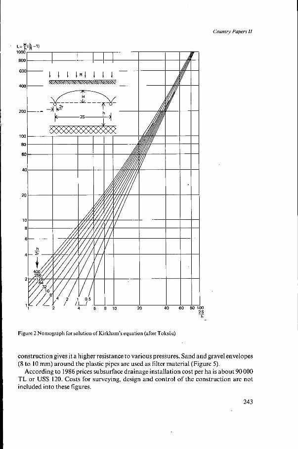
A detailed groundwater table map and barrier map is prepared during the survey of the drainage area. Augerholes are drilled in gridpoints 400 m apart up to 3.0 m depth. Hydraulic conductivity values (K) are determined by means of these augerholes. The average of 4 to 6 values in neighbourhood holes are used for calculating drain spacings. The drainage coefficient is assumed 2 "/day for irrigated areas. After collecting these data the Toksöz and Kirkham nomograph in Figure 2 is used for calculating the drain spacing.
The following is an example of drain spacing calculation in Manisa- Saruhanli- Nuriye project in 1985. Given: Average hydraulic conductivity (K) of 6 auger holes
K = 0.56mIday h = 8.00 m (depth to barrier) H = 0.60m 2r = O. 10 m (drain pipe diameter)
R = 2 "/day (drainage coefficient)
Solution:
0.60 0.56 h 8.00 8.00 (,,oo2 1) = 21.5 and- = - = 80 H K h R 2r 0.10
L = -(-- 1) = __ --
Using the nomograph in Figure 2 gives
2s - = 8.5 and S = 8 x 8.5 = 68.0 m, h
which is the calculated drain spacing for that particular area.
The groundwater table is kept generally 0.90 to 1.50 m below ground level depending on the rootzone of the major crops and taking into account the salinity of the ground- water. For this reason lateral drains are laid at a depth varying from 1.50 to 2.10 m, but in most cases at 1.80 m below the surface.
7 Drainage construction
The trencher is the most common and convenient machine for installing subsurface drainage systems. Former trenchers made in U.S.A. are replaced by German or Dutch made trenchers which are lighter and faster (Figure 3).
Excavators are used in constructing or cleaning of open drainage canals (Figure 4).
The flexible perforated PVC pipes are used for agricultural drainage applications. They are manufactured in Turkey as 50-200 m coils with a diameter range of 50 mm to 200 mm. Its flexible quality enables easy installation into the trenches and its spiral
242
Country Papers I I
3 80 100
h E
Figure 2 Nomograph for solution of Kirkham’s equation (after Toksöz)
construction gives it a higher resistance to various pressures. Sand and gravel envelopes (8 to 10 mm) around the plastic pipes are used as filter material (Figure 5) .
According to 1986 prices subsurface drainage installation cost per ha is about 90 O00 TL or US$ 120. Costs for surveying, design and control of the construction are not included into these figures.
243


Country Papers II
9 Problems and bottlenecks in drainage systems
Although regular maintenance and cleaning of silt and weed control in open (main) drainage canals are periodically carried out by DSI, stabilization of canal embank- ments, siltation and weed problems are not completely solved for open drainage canals. Weeds and siltation minimize the original design capacities of open drains. As a result, subsurface drainage systems cannot discharge as free flow into these canals. Sometimes submerged flow occurs from drainage laterals and sometimes they are completely clogged because of siltation. This situation is rather common in the lowlands where there is not enough slope for open drainage canals.
Also the management and maintenance work of subsurface drainage systems is not very regular. Farmers, farmer’s cooperatives or related governmental agencies (KÖy Hizmetleri) carry out cleaning and repair of installed subsurface drainage systems in case clogging or a visible damage occurs to the pipes or to the old siltation boxes. Clearly there must be a better coordination between the related governmental agencies, DSI, KÖy Hizmetleri and farmers on the management and the maintenance of the drainage systems after installation.
References
Akgiil, H. and I. Akyiirek. 1979. Toprak Asinimi (Erosion) T.C. Köyisleri ve Kooperatifler Bakanligi,
Batur, K. and S. Sener. 1984. Söke Ovasi Drenaj ve Toprak Islahi Sorunlari, T.C. Tarim Orman ve Köyisleri
DSI 1980. Giineydogu Anadolu Projesi. T.C. Enerji ve Tabii Kaynaklar Bakanligi DSI Genel Miidiirliigii,
DSI 1986. Dams and Hydroelectric Power Plants in Turkey, DSI Matbaasi, Ankara. Framji, K.K. and I.K. Mahajan. 1969. Irrigation and Drainage in the World, Vol. 11. Turkey, pp. 1092-1 109.
ILRI 1974. Drainage Principles and Applications, International Institute for Land Reclamation and Im-
Köy Hizmetleri. 1986. KÖy Hizmetleri Calismalari, 1985 Revize Programi ve KÖy Hizmetleri Atlasi. T.C.
Luthin, J.N. 1966. Drainage Engineering, John Wiley and Sons, Inc. New York. Oakes, H. 1954. Soils of Turkey. Printed by Dogus Ltd. Sirketi Matbaasi Ankara, Turkey. TOPRAKSU 1969. Drenaj, Teknik Standartlar Serisi No: 4 T.C. Köy Isleri Bakanligi, Ankara. TOPRAKSU 1975. Topraksu Istatistik Biilteni, Yayin No. 305-225 T.C. Köyisleri Bakanligi Yayini, An-
TOPRAKSU 1978. Tiirkiye Arazi Varligi, Kullanma Siniflar, Sorunlar. T.C. Köyisleri ve Kooperatifler
TOPRAKSU I98 1. Topraksu Istatistik Biilteni, T.C. Köy Isleri ve Kooperatifler Bakanligi TOPRAKSU
USDA 1973. Drainage of Agricultural Land, Soil Conservation Service, U.S. Dept. ofAgriculture Published
Toprasku Genel Miidiirliigu Yayini, Ankara.
Bakanligi Menemen Köy Hizmetleri Arastirma Enstitiisii Raporu.
Ankara.
K I D , New Delhi.
provement, P.O. Box 45, Wageningen, The Netherlands.
Tarim Orman ve Köyisleri Bakanligi, Ankara.
kara.
Bakanligi TOPRAKSU Genel Miidiirliigii Yayini, Ankara.
Genel Miidiirliigii Yayini Ankara.
by Water Information Center, Inc. New York.
246

Country Papers I I
Development of drainage in the Middle Awash Valley in Ethiopia T. Woudeneh Water Resources Development Authority, Addis Ababa, Ethiopia
1 Introduction
Drainage development in Ethiopia is relatively recent. Only few areas benefit from agricultural drainage at present. In the highlands where most of the rainfed agriculture is located, the introduction of proper drainage systems could increase agricultural production. No attempt has been made to reclaim lands that suffer from lack of drain- age for agricultural production.
In the lowlands where most of agricultural development is uneconomical without irrigation, the importance of drainage has been realized. In the earlier irrigated agricul- tural developments no provision was made for drainage. Most of these areas are now suffering from waterlogging or salinity due to absence of proper drainage systems. In the more recent developments, surface drainage systems are implemented together with the irrigation system.
The potential for drainage development is high in the rainfed and irrigated agricul- tural sectors. In the irrigation subsector alone some 2 million ha of land has been identified for possible large scale irrigated agricultural development in the coming decades. Most of these areas cannot be economically productive without drainage.
At present irrigation development has concentrated along the Awash River Basin. Of the net potential irrigable lands in the basin about 67 O00 ha have been developed. The major crops are cotton, sugarcane, banana, maize and some horticultural crops.
In the Middle Awash Valley alone some 17800 ha is under irrigation (Figure 1). The soils of the area consist mostly of alluvial sediments. The sediments are often characterized by high contents of silt, the texture ranging from clay to silty clay loam, silt loam with some sandy loam, loamy sand and fine sand. The Middle Awash Valley is located in an area with a semi-arid climate and a bi-annual rainfall pattern. The mean annual rainfall is 560 mm. Mean monthly temperatures range from 22.5"C in December to 38.5"C in June. The annual potential evaporation is estimated at 2400 mm. The Awash River has a pronounced seasonal regime and flooding is a frequent event during August and September. Extensive catchments to the east and west of the river drain towards the Awash river and are characterized by short duration flood peaks resulting from storm rainfall.
Irrigation development has concentrated in the Middle Awash Valley as a result of the high yields achieved. An average of 35 quintalslha of seed cotton on the recently developed Amibara Scheme has been achieved. These yields cannot be sustained with- out proper drainage provision. As a result of this awareness, the study and implementa- tion of drainage projects has commenced in this region.
247

Country Papers I1
O 10 2p km
-road
-railway
-river
Figure I Location of Middle Awash Development project in Ethiopia
2 Drainage requirements
In the Middle Awash Valley drainage for an irrigation unit which usually has a size of about 10 O00 ha requires two systems, an internal and an external drainage system.
The internal system drains off excess water to a disposal point at the project bound- ary. This system provides: drainage of excess surface water from rainfall and irrigation, excess canal water and groundwater.
For drainage of excess surface water well designed land levelling of irrigated plots
248

Country Papers I1
is essential. Field ditches that transport water to higher order drains are constructed at the end of each field, that has an average size of 20 ha.
Irrigation canals are provided with tail escape structures so that any excess or un- wanted canal flow can directly be discharged into a drainage canal. This system in- creases the flexibility in the operation of the irrigation system.
Groundwater drainage for salinity control is the most important and probably the most expensive and difficult part of the drainage system. Irrigation and drainage stu- dies have indicated that land brought under irrigation will suffer from a rising ground- water table and salinization after implementation of irrigation projects. Piezometers and observation wells in the Amibara area have shown that the groundwater rises at an average rate of about 1 m each year so that salinity will start to appear within ten years after the introduction of irrigation. To control this occurrence deep subsur- face or open drains should be constructed before the groundwater reaches the rootzone and soil salinity starts to affect yields. In this respect measures should be taken before the groundwater comes within 2 m below ground level.
The external drainage system collects excess water both from the internal system and from outside the irrigation unit boundary for conveyance to the final disposal point. The land suitable for irrigation development suffers from two sources of flood- ing as a result of the topography of the area. The irrigated land reflects the recent geomorphological history of the Middle Awash Valley, where an extensive alluvial plain has been built-up by deposits from the Awash River. The irrigated'areas lie on both riverbanks and are in general bounded by escarpments which gently slope towards the land suitable for cultivation. Because of this topographic condition the irrigated lands must be protected against flooding by rivenvater or from local run-off.
Earth banks with an average height of about 2 m are constructed parallel to the river to protect the irrigated areas from river flooding. Where appropriate, flood chan- nels are provided to drain flood water in order to prevent stagnation and recharge to the groundwater of the irrigated area.
The irrigated areas are bounded on one side by an escarpment that rapidly generates floods of high magnitudes. Earth dikes with parallel drainage channels are constructed for protection against this run-off.
3 Progress of drainage construction and future prospects
Large scale irrigated agricultural development in the Middle Awash Valley started about 15 years ago. At the initial stage of development, drainage was not considered essential and some of the earlier developed farms lack proper drainage systems. At present most of these farms are suffering from waterlogging and soil salinity. In the more recently developed farms proper surface drainage and flood protection is pro- vided and proper planning for subsurface drainage implementation is incorporated.
At present, besides the Gewane area, some 15 O00 ha are under irrigated agricultural production, mainly cotton but also banana, citrus, tobacco. A surface drainage system is only provided for about 7200 ha. Implementation of large scale subsurface drainage has not yet started. The recent Amibara Master Drainage Plan Study indicated that
249

Country Papers I1
in 1985 some 2500 ha of the irrigated land needed immediate drainage implementation and that by 1990 subsurface drainage will be needed on some 5000 ha. An irrigable area of about 39650 ha has been studied to feasibility level in all aspects including soils for land classification, irrigability and drainability classifications and outline de- sign of all components. Detail design for subsurface drainage covers about 5000 ha, while surface drainage design covers about 24 200 ha. Construction of surface drainage has been implemented on about 48% of the area under irrigation while subsurface drainage only covers a pilot area of 30 ha. There is a considerable potential for future drainage work as shown in Table 1. This programme is based on the premises that: - Sustained irrigated development without drainage cannot be economically produc-
- Surface drainage should be constructed together with the irrigation system; - Groundwater will rise to within the rootzone and that salinity and waterlogging
will start to affect the yields about 10 years after irrigation implementation.
tive;
According to this programme, all areas that are currently under irrigation need surface drainage immediately and subsurface drainage in 1995, when construction starting in 1986. The areas that would be brought under irrigation in 1990 should have surface drainage completed at the same time with irrigation implementation and subsurface drainage in 2000. The potential in 2000 as given in Table 1 is that 39 650 ha will need surface drainage and about 28 800 will need subsurface drainage.
The implementation of drainage work as indicated in Table 1 will be governed by the following important factors: - Priority of irrigation development; - Availability of technical know-how for study, design and implementation; - Availability of financial resources; - Organizational capability for irrigation and drainage projects implementation; - Availability of drainage construction materials.
4 Drainage criteria
The formulation of drainage criteria was influenced by: - The efficiency of the irrigation system; - The drainage requirement for removing excess irrigation, rainfall, run-off and river
- The crop tolerance to waterlogging and salinity; - The soil, ranging from heavy clay to sand; - Topography: the slope of land adjacent to irrigated areas and its steepness or the
presence of constructions along the river affect the width of flood channels and the dike heights necessary for flood protection and routing;
- Vegetation: the degree of vegetative cover along the river and on the areas adjacent to the irrigated areas influence the provision of flood protection structures.
A summary of drainage criteria used in the design of Melka Sadi Amibara System
flooding;
250
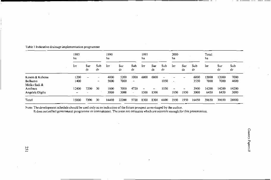
Table 1 Indicative drainage implementation programme
I985 1990 1995 2000 Total ha ha ha ha ha
Irr Sur Sub Irr Sur Sub Irr Sur Sub Irr Sur Sub Irr Sur Sub dr dr dr dr dr dr dr dr dr dr
Kesem & Kebena 1200 - - 4000 5200 1000 6800 6800 - - - 6000 12000 12000 7000 Bolhamo 1400 - - 5600 7000 - - - 1050 - - 3550 7000 7000 4600 Melka Sadi & Amibara 12400 7200 30 1800 7000 4720 - - 5550 - - 3900 14200 14200 14200 Angelele Digilu - - - 3000 3000 - 1500 1500 - 1950 1950 3000 6450 6450 3000
Total 15000 7200 30 14400 22200 5720 8300 8300 6600 1950 1950 16450 39650 39650 28800
Note: The development schedule should be used only as an indication of the future prospect as envisaged by the author. It does not reflect government programme or commitment. The areas are estimates which are accurate enough for this presentation.

Country Papers I1
(5000 ha) is given in Annex A. Some important considerations in the formulation of the criteria are briefly outlined below.
A major consideration in designing surface drainage is the tolerance of the crop to waterlogging. Well established plants will tolerate a 'wet-foot' condition for up to 24 hours and any rainfall excess falling on fields that have just been irrigated will have to be drained within 24 hours. Based on this assumption run-off coefficients were calculated using rainfall data from the area. Observations have shown that drain- age systems based on the above assumption have, on the average, worked well.
With regard to excess canal water, practical operational considerations have indicat- ed that for field and tertiary drains full canal rejections should be accommodated. For secondary, primary or main drains a factor of O. 15 l/s/ha, estimated from rejection flows, was applied. The channel capacity is based on the assumption of the design rainfall excess and the irrigation excess not occurring at the same time. Even though at times such an event has occurred, it did not cause major damage.
The Middle Awash Valley is subjected to annual flooding by the Awash River. A design flood with a 20 years return period was used for determining dike heights. For the protection of farms from adjacent run-off, a rainfall analysis to determine the run-off coefficient was made and a 10 years return period flood was used for the dike heights.
The drainage criteria for subsurface drainage were based on the rate at which the watertable must be lowered after an instantaneous rise resulting from irrigation. The subsurface drain should satisfy the requirement of cotton, the major cash crop. The rate of drawdown, drainable excess and drainage depth is determined for this crop. Criteria for cotton are assumed satisfactory for other crops. The drainable excess was estimated for a field irrigation efficiency with 25% percolation. This gives a drainable excess of about 2.5 "/day. This value was confirmed by pilot drainage trials conduct- ed on 30 ha and by the observed rate of groundwater rise. The drain depth is deter- mined by the balance between the salinization during the fallow season and the leach- ing during the irrigation season to a level not detrimental to crop growth. Taking into account the soil hydrological characteristics, a drain depth of about 2 m below ground surface was found satisfactory. The drain spacing was then optimized for a series of drawdown criteria ranging from a slow rate of recession as one extreme for wide spacing and a rapid rate of recession as the opposite extreme for narrow spacing. The subsurface drainage design parameters for cotton on soils of different drainability classes are summarized in Table 2.
252

Country Papers II
Table 2 Subsurface drainage design parameters for cotton
Soil drainability K D U hm ho ht class (m/day) (m) (ml (m) (4
Ia 2.0 o. 1 .O9 .o 1 1.79 1 .O7 . I O 1.70 0.98 .40 1.40 0.68 .80 1 .o0 0.28
1 .o0 0.80 0.08 1 .o5 0.75 0.03
Ib 2.0 0.7 .O9 1 .O5 0.75 0.03 IC 2.0 1.7 .O9 1 .o5 0.75 0.03 Id 2.0 3.2 .O9 1 .O5 0.75 0.03 IIa 1.4 o. 1 .O7 1 .o5 0.75 0.03 IIb I .4 0.7 .O7 , 1.05 0.75 0.03 I k I .4 1.7 .O7 1.05 0.75 0.03 IId 1.4 3.2 .O7 1 .O5 0.75 0.03
Note: hm = minimum permissible depth of watertable below ground surface ho = initial watertable height above drain ht = final watertable height above drain D = depth from drains to impermeable layer K = saturated hydraulic conductivity u = drainable pore space
The same set of values for hm, ho, and ht as given for class Ia has been used to generate drain spacings for each soil drainability class. Soil drainability class I = coarse texture/silt loam, sandy loam, loam etc. Soil drainability class I1 = other textural class except clay Sub-class a: impermeable layer: less than 2.00 m
b: impermeable layer: 2.00-3.00 m c: impermeable layer: 3.00-4.00 m d: impermeable layer: more than 4.00 m
5 Method of construction
A major surface drainage construction project has been implemented on an area of about 7000 ha in the Amibara Irrigation Project and construction was carried out by contractors engaged through competitive bidding.
The flood protection embankments are designed as a trapezoidal section with minimum of 3 m top width, 2: 1 side slopes and average height of around 2 m.
Drainage channels with capacities above 400 l/s are excavated using a backacting hydraulic excavator. Drains of less than 400 I/s capacity are constructed by labourers using shovels and pickaxe or by grader machine.
All excess water is returned to the Awash river. The outfall structures are designed to prevent back flow at high river stages and also to discharge excess drain water
253

Country Papers 11
at the same time. For this purpose the outfall structures are provided with one-way gates and rejection spillways.
Subsurface drainage has been constructed on a pilot project of 30 ha. There is no experience in this respect in the country. Large scale subsurface drainage on 5000 ha will be undertaken soon. It is expected that the implementation will be completed in 1990. The installation of drain pipes both for lateral and collector drains will be carried out by drainage trenching machines. Comparative analysis has shown that the use of such machines will make the construction faster and cheaper than other methods such as use of labour. The perforated pipes are to be produced on the site by a pipe making plant. The comparative estimates made with other means of provid- ing pipes show this to be economically attractive and technically feasible. Deep open drainage channels would be excavated by hydraulic backacting equipment and trimmed by hand. The use of motorized scrapers might be appropriate for the construc- tion of flood embankments and associated drain channels.
6 Drainage development cost
Actual costs for pipe drainage are not available as this kind of work has not yet been executed on a large scale in Ethiopia. The surface drainage work has been executed between 1979 to 1983 on the Ambira Irrigation Project. Unit rates based on 1978 tenders were applied for costing. These rates were updated to 1985 prices in the Master Drainage Study and then used for estimating drainage development cost on an area of 14 200 ha over a period of 15 years. Some cost unit rates are summarized in Table 3.
Table 3 Cost per unit rate (1985 prices)
Description Unit Cost unit rate* (Birr)
Excavation for structures m3 11.9 Excavation for drains and place in embankments m3 3.6 Compact fill in embankments m3 2.5 Reinforced concrete m3 284 Reinforced steel kg 2.9 Masonry m3 165 Reinforced concrete pipe - 600 mm m 284 Reinforced concrete pipe - 150 mm m 426 Supply and installation 60 mm PVC field laterals and surrounds m 4.6 Supply and installation PVC collector pipe - 150 mm 10.8 Supply and installation PVC collector pipe - 225 mm 19.6 Supply and installation PVC collector pipe - 300 mm 33.0
m m m
* Includes 10% allowance for minor items 1 US$ = Birr 2.07
254

Country Papers 11
The drainage implementation cost for 14 200 ha at 1985 prices is estimated to be US$ 3 100/ha. This includes construction of flood protection works, land improvement, construction of associated structures and provision for housing and for supervising operation and maintenance.
7 Project organization and management
The Water Resources Development Authority (WRDA), under the National Water Resources Commission, is the national body responsible for the development and utili- zation of surface water resources in the country. The power and duties of the Authority include study of water resources, implementation of water resources projects and ad- ministration of their operation and maintenance.
By virtue of this power the Authority has undertaken the study, design and imple- mentation of irrigation and drainage projects and after implementation operates and maintains these projects. For project implementation the Authority establishes project executing offices with specific mandates. These executing offices usually carry out feas- ibility studies of projects or their implementation.
Once the implementation of projects are completed, they are handed over to other institutions responsible for production operation. The Authority has a department which is responsible for operation of major water structures, their maintenance, the administration of water utilization and the levying of charges for operation and main- tenance costs and the repayment of loans obtained for project development.
The Authority usually engages the services of specialized consulting firms or experts for project preparation, design and supervision. The Authority has executed the following projects in the Middle Awash Valley:
- Irrigation feasibility study 39 O00 ha - Design for irrigation 11 O00 ha - Irrigation implementation l0000ha - Drainage study and outline design 14000ha - Detailed drainage design 5 O00 ha
8 Maintenance of drainage systems
At present maintenance is limited to surface drainage and flood protection systems along with other irrigation structures. The maintenance is organized, based on the facilities and equipment required to carry out specific aspects.
The main consideration is whether a maintenance activity can be executed economi- cally and technically by machine or labour. In this respect, maintenance activities that mainly require labour are the responsibility of production operating entities and those that require machines and skilled manpower are the responsibility of the Water Re- sources Development Authority. The maintenance responsibility is divided as follows:
-255

Country Papers I1
- Production Operation Entities are responsible for maintenance of tertiary and field drains, less than about 400 l/s. They employ labourers for maintenance activities;
- WRDA is responsible for all high-order drains, drains mutually used by more than one entity even if the capacity is small, flood protection dikes etc. WRDA has a maintenance organization in the Middle Awash Valley equipped with machines such as excavators, dozers, graders, dump trucks and appropriate skilled manpower to manage the maintenance work and to operate and maintain the machines.
The most important maintenance requirement is the removal of weeds and desilting of channels. The weeding and desilting work has to be done at least once a year and in some cases twice.
Repair to gates, structures, etc. are also done annually. So far the maintenance acti- vities on the existing development are effective and satisfactory.
9 Conclusion
Agricultural drainage has recently started in Ethiopia. The Middle Awash Valley is one of the priority areas for drainage construction. Surface drainage has been imple- mented with irrigation development. A Master Plan for subsurface drainage construc- tion has been prepared. The awareness exists that without proper drainage sustained irrigated agricultural development cannot be maintained in places like the Middle Awash Valley.
’ In order to achieve the target for drainage implementation in the region, particular attention should be given to the following points: - Commitment and planning of irrigation and drainage projects including financial
- Build-up of organizational and technical capability and capacity through training
- Constant and accurate recording, monitoring and evaluation of irrigation practices
- Continuous research activity on the unique irrigation and drainage problems of
- Build-up of construction capability and capacity; - Preparing drainage materials.
requirements;
and assistance to undertake drainage projects;
and timely observation of the occurrence of drainage problems;
the region;
256

Country Papers II
Annex A
Design criteria'
Criterion Assigned Design consideration value
1 Flood dikes
1.1 Awash River Flood Protection Dike
River dike to withstand return period flood of
Minimum freeboard
Dike top width
Side slopes
Cross fall to dike top (towards river)
Topsoil stripping under embankment (minimum)
Compaction to embankment (Proctor density)
Minimum reserve between dike and adjacent rivenvay
20 years
0.5 m
3.0 m
I in2
I in 30
0.15111
95%
100 m
1.2 Eastern catchment flood dike and drain
Dike to withstand return period flood of I O year
Minimum freeboard
Dike top width
Side slopes
0.5 m
3.0 m
1 in2
Minimum reserve between dike and drain
Minimum reserve between dike and toe of adjacent foothills 150m
Topsoil stripping under embankment (minimum) 0.15 m
Compaction to embankment (Proctor
Minimum width of flood channel
Minimum depth of flood channel (cut and fill balance) 0.5 m
50 m
density) 95%
20 m
Optimized cost/benefit
Contingency/safety factor
Vehicular access
Stability
Surface drainage
Elimination of preferential seepage path/ stability
Stability/seepage
Flood reserve for attenuation, safety re- serve against high velocity/erosion of dike
Qualitative assessment of appropriate period
Contingency/safety factbr
Vehicular access
Stability
Limit velocity/erosion adjacent to dike
Flood reserve
Elimination of preferential seepage path/ stability
Stability/seepage
Provision of preferential flow path
Provision of preferential flow path
I ) Water Resources Development Authority 'Master Drainage Plan for Melka Sadi and Amibara Area, Vol. 7 Annex D; Engineering,' Halcrow, July 1985.
257
Country Papers II
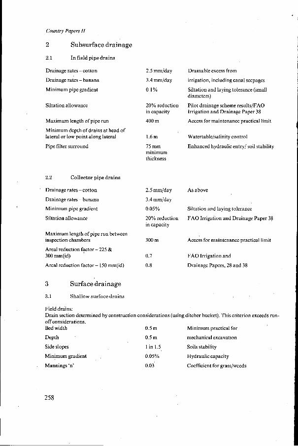
2 Subsurface drainage
2.1 In field pipe drains
Drainage rates - cotton
Drainage rates - banana
Minimum pipe gradient
Siltation allowance
Maximum length of pipe run
Minimum depth of drains at head of lateral or low point along lateral
Pipe filter surround
2.2 Collector pipe drains
Drainage rates - cotton
Drainage rates - banana
Minimum pipe gradient
Siltation allowance
Maximum length of pipe run between inspection chambers
Areal reduction factor - 225 & 300 "(id)
Areal reduction factor - 150 "(id)
2.5 "/day Drainable excess from
3.4 "/day
o. 1 %
irrigation, including canal seepages
Siltation and laying tolerance (small diameters)
Pilot drainage scheme results/FAO Irrigation and Drainage Paper 38
Access for maintenance practical limit
20% reduction in capacity
400 m I
1.6m Watertable/salinity control
75 mm minimum thickness
Enhanced hydraulic entry/ soil stability
2.5 "/day
3.4 "/day
0.05%
20% reduction in capacity
300 m
0.7
0.8
As above
Siltation and laying tolerance
FAO Irrigation and Drainage Paper 38
~ c c A for maintenance practical limit
FAO Irrigation and
Drainage Papers, 28 and 38
3 Surface drainage
3.1 Shallow surface drains
Field drains: Drain section determined by construction considerations (using ditcher bucket). This criterion exceeds run- off considerations. Bed width 0.5 m Minimum practical for
Depth 0.5 m mechanical excavation
Side slopes 1 in 1.5 Soils stability
Minimum gradient 0.05% Hydraulic capacity
Mannings 'n' 0.03 Coefficient for grass/weeds
258

Country Papers II
Tertiary drains: Drainage coefficient
Bed width
Minimum gradient
Mannings ‘n’
1.2 I/sec/ha or 1 in 5 year rainfall/run-off estimate , tertiary canal rejection flow (100% design)
0.75 m Nominal standards for
0.05% velocity roughness and
0.03 contingency allowance (in freeboard)
Minimum freeboard 0.25 m
Secondary drains: Drainage coefficient
Mannings ‘n’
Minimum freeboard
Main drain: Drainage coefficient
Mannings ‘n’
Minimum freeboard
1.2 l/sec/ha or secondary canal rejection flow (100% design)
0.025
0.25 m
As tertiary drains, roughness coefficient based on maintained flow section
1 .O I/sec/ha or sum ofcanal estimate rejection flow (100% design)
0.025 Maintained flow section
0.50 m Contingency
I in 5 year 24 hour rainfall/run-off
3.2 Deep surface drains (conveying subsurface drainage flows)
Normal flow discharge coefficient
Mannings ‘n’ secondary and main drain
Normal flow level, below centre-line of subsurface pipe outlets
Maximum drain depth without berm
Side slopes
Berm width (where required)
Design flood flow, sum of
design normal flow and surface
storm run-off (or rejection)
flows for secondary main drains
Minimum freeboard Main drain
Secondary drain
0.35 I/sec/ha
0.025
0.15m
3.5 m
1 in 1.5
4.0 m
0.35 I/sec/
ha + l .O l /
sec/ha =
1.35 I/sec/ha
0.5 m
0.25 m
Combined rejection and subsurface drain- age flows
Maintained flow section
Operational contingency allowance/ facilitate inspection
Stability/access for maintenance
Soil stability
Minimum access for maintenance
Superimposing flood
run-off on normal
operating condition
Contingency allowances
259

Country Papers II
3.3 Desirable velocities i n open drains
Minimum (for normal flow)
Maximum (for peak flow)
4 Drainage structures
Maximum culvert headloss at normal flow
Minimum pipe velocity
Maximum pipe velocity
Factor of safety on seepage (exit gradients)
Angle of internal friction of backfill
Cohesion of backfill
Safe bearing capacity of foundations
Assumed nominal concrete strenght at 28 days
Filter gradings (for rip-rap)
0.4 m/sec
0.8 m/sec
0.05 m
Not less than drain velocity
3.0 mlsec
5.0
30"
O
100 kN/m2
20 N/mm2
Designed to USBR recom- mendations
Prevention of bilharzia snail
Scour velocity
Cost minimization
Silt prevention
Energy dissipation
Soil stability
Standard strength class
Stability/ permeability of underlying soil
260