Embed Size (px)
Citation preview

Development Of Enabling Technologies For
A Pressurized Dry Feed Oxy-coal Reactor
Project Review
DE-FE0029157
Bradley Adams ([email protected])Andrew Fry ([email protected])Dale Tree ([email protected])
Transformative Power Generation Virtual Project Review MeetingSeptember 28, 2020
1

2
Project Overview
▪ Objective: Develop technologies and data that will enable design and operation of a pressurized oxy-coal combustor
▪ $1.4M program ($1.1M DOE, $0.3M cost-share)
▪ 5-yr program (10/1/16 – 9/30/21)
▪ Team
• Brigham Young University (Adams, Fry, Tree, students)
• Reaction Engineering International (REI)
• CPFD Software
2

3
Technology Deliverables
▪ 100 kWth 20-bar pressurized oxy-coal reactor
▪ Scalable pressurized dry coal feed system
▪ Scalable O2-CO2-coal burners/firing systems for diffusion flame and flameless combustion
▪ Measurement data
▪ Mechanistic process model to guide reactor scale-up and plant integration
4
POC System Overview
Ash Tank
Molten slag collection
Coal Feed
CO2 + Coal
OPTO 22
Control System
Burner
Gas Feed
O2, CO2, NG

5
Coal Feed Design Concept
▪ Modeled with Barracuda CFD software
▪ Fluidize coal in hopper for transport; add dilution CO2 as needed
• Sufficient coal flow and CO2–to-coal ratio
• Decoupling of fluidization and dilution flows
• Flow sufficiently steady for burner operation
• Sensitive to gas inlet design
▪ Piping system has roping
Design Concept
6
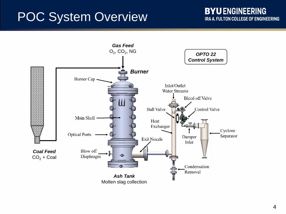
Fluidized Bed Design
Barracuda CFD Modeling
of design concept ▪ CO2 fluidizes coal in hopper
▪ Mixture transported to horizontal pipe
▪ Dilution CO2 added in pipe
Inlet A Outlet C Outlet E Inlet B Outlet D
CO2
Fluidization Flow (g/s)
CO2 Flow Through Vent
(g/s)
CO2 Flow Exiting Hopper
(g/s)
CO2 Dilution Flow (g/s)
Coal Flow at Exit (g/s)
Exit CO2 to Coal Ratio
0.384 0.034 0.350 3.350 5.757 0.64
0.500 0.150 0.350 3.234 5.712 0.63
0.850 0.500 0.350 3.350 4.933 0.75
0.384 0.034 0.350 6.700 5.985 1.18
0.734 0.034 0.700 3.000 10.588 0.35
1.200 0.500 0.700 3.000 11.130 0.33
Fluidizing
CO2
Dilution
CO2
To Reactor
CO2 + Coal
Vent CO2
Fluidized Coal

7
Bench-Scale Test Feeder
Dilution
gas inlet
Fluidization
gas inlet
To load
cell
Flow exit
and filter
To
load
cell
Coal cell
Fluidization
gas vent
Bench-Scale Feed SystemTesting Validates Concept
0
0.2
0.4
0.6
0.8
1
1.2
1.4
0 50 100 150 200 250
Coal
in H
oppe
r (k
g)
Opto Data Points (~ seconds)
Coa
l in
Hop
pe
r (k
g)
Time (s)

8
Full-Scale Coal Feeder
▪ ~13.6 kg/hr, 6 hrs
▪ Hydrostatic Testing to 34 bar
▪ Load-cells calibrated
Fluidizing CO2
Dilution CO2
To Reactor
Distributor Plate
Vent CO2
Coal Load Valve
Load CellsFeeder Controls

9
Flame Types
▪ Diffusion flame
• Coal concentrated in center
• Currently installed
▪ Flameless combustion
• Coal distributed at inlet
• Future design
▪ Design approach
• Previous oxy-coal burner design and testing experience
• CFD modeling of reactor combustion and heat flux
Diffusion Flameless

10
Burner Concepts
• Baseline Design
• Coal conveyed with CO2
in primary (~1:1)
• Mixed O2 and CO2 in secondary annulus
• Mixed O2 and CO2 in tertiary lances
• CO2 for temperature and momentum control
Simulations from Reaction Engineering International
Case 1 Case 2 Case 3Case 1 Case 2 Case 3
CO2/Coal Ratio 1.8:1 8.0:1 4.2:1
%O2 Non-Coal Feed 20 20 10.4
Coal Vel. (m/s) 5.3 0.51 5.0
Inner O2 Vel. (m/s) 1.03 0.5 5.2
Outer O2 Vel. (m/s) 10.5 0.54 5.3

11
Burner Design
Connections From MFCs to BurnerBurner Installed
Burner Testing

12
PCHT Model
▪ Fast-running physics-based model
▪ Design screening, scale-up, plant integration
▪ Jet mixing, particle transport, reactions, radiative heat transfer
▪ Use adaptive dimensionality
• Use 3D only where necessary
• Biggest challenge is radiation
▪ Compare to reactor test data
▪ Model reactor scale-up, compare to CFD results

13
Radiation Calculation Speed-up
Schematic of intensity rays for fully
3D vs 3D/axi-symmetric Single
Weighted Ray (SWR) technique Median difference in incident wall flux
< 1% for all meshes
Moving from fully 3D to 3D/axi-symmetric/1D dimensionality reduces
computational time with minimal loss in accuracy
274% speed-up
273% speed-up
270% speed-up

14
POC Reactor Design
Four Refractory-Lined
Sections
1) Top Section - Dome cap,
houses Burner
2) Burner - Transports
primary, secondary and
tertiary flows into reactor
3) Main Section - 1.8 m
combustion zone with
optical access ports and
embedded wall TC
4) Bottom Section - Slag
collection and exhaust
nozzle for flue gases
Total reactor weight ~ 6 tons
Port 1
Port 2
Port 3
Port 4
Port 5

15
POC Reactor15
Main Shell
Heat Exchanger
Emergency
Pressure Relief
Valve
Cooling Spray

16
Reactor Optical Access
• Sapphire window assemblies have been machined and installed to allow optical measurements to
be taken with reactor pressures at 20 bar
• These have been hydrostatic tested to 34 bar
• Integrated into assembly design
• Purge system
• Mounts for optical devices (radiometer, laser, passive FTIR)

17
Heat Flux
Narrow Angle Radiometer (NAR)Multi-depth Thermocouples
• Five Sets (along reactor axis) are installed
and operating nominally
• Provide both inside refractory surface
temperature and total heat flux
• System is ready for testing
• Prototype is completed along with extensive calibration and
uncertainty analysis on a black body radiator
• 4 more devices are under construction
• Electronics complete
• Mechanical components expected next week
• One of these will be evaluated against Chalmers and
University of Utah NARs (published results)

18
Temperature and Soot
Optical Pyrometer / Passive FTIRTwo-color Laser Extinction
(Soot and Ash)
• A table has been designed and fabricated to mount
the laser on one side of the rector and integrating
sphere on the opposite side of the reactor
• Curtain holders have been installed to protect users
from stray laser light
• System is ready for testing – awaiting pressurized
flame conditions
• A holder has been designed and fabricated for
outside mounting of optical collection probe
• Purge system has been installed
• System is ready for testing
• If purging does not work, a design and fabrication for
internal installation will be necessary

19
Reactor Status
▪ Completed:• Main reactor with diffusion burner system
▪ Pressurized air, NG, O2 and CO2
• Pressurized coal feed system
• Flue gas cooling / clean-up system
• Control system
• HAZOP review and updates
• Pressure burst test
• Refractory cure
▪ Immediate Next Steps:• Pressurized natural gas combustion tests
• Pressurized coal combustion tests

20
Shakedown Test Results
0
10
20
30
40
50
60
70
80
90
100
1 6 20 29 35 42 48 54 60 66 72 78 84 90 99
Firi
ng
Rat
e (
KW
)
Time (minutes)
0
200
400
600
800
1000
1200
0
1
2
3
4
5
6
1 6 20 29 35 42 48 54 60 66 72 78 84 90 99
CO
(P
PM
)
O2
(% V
ol)
Time (minutes)
O2 CO
• The purpose of these tests is to
verify that the equipment as
installed was capable of:
• Spanning the range of
expected operating
conditions
• Stabilize a natural gas flame
at atmospheric pressure
• Identify any problems with
equipment configuration
• Data presented on this slide are
concerned with firing rate and flame
stability
• Data presented on the next slide
demonstrate the functionality of the
multi-depth thermocouples
Equivalence ratio near 1/ analyzer

21
Shakedown Test Results
Wetted Refractory Surface Temperature
(Calculated)
0
200
400
600
800
1000
1200
1400
0 5 10 15 20 25 30 35 40 45Te
mp
era
ture
(K
)
Time (minutes)
Port 1 Port 2 Port 3 Port 4 Port 5
0
200
400
600
800
1000
1200
1400
0 5 10 15 20 25 30 35 40 45
Tem
pe
ratu
re (
K)
Time (minutes)
Port 1 Port 2 Port 3 Port 4 Port 5
Inner B Thermocouple Temperature
Outer B Thermocouple Temperature
0
200
400
600
800
1000
1200
1400
0 5 10 15 20 25 30 35 40 45
Tem
pe
ratu
re (
K)
Time (minutes)
Port 1 Port 2 Port 3 Port 4 Port 5

22
Safety – HAZOP & Inspection
• A Hazard and Operability Study was performed in June of 2019
• Participants in the study included:
• College of Engineering Safety Personnel
• College of Engineering Lab Managers
• BYU Risk Management
• Project Professors and Graduate Students
• Invited Engineers from Industry with Similar Processes
• 76 Action Items were generated in this study that included:
• Hardware Reconfigurations
• Interlock Installation
• Control Logic Modifications
• Standard Operating Procedure Modifications
• All action items have been addressed and tested
• State Pressure Vessel Inspection has been passed and Operating Permit
Obtained

23
Summary
• A 100 kWth 20-bar pressurized oxy-coal reactor has been
installed at BYU with corresponding systems
• Pressurized dry pulverized coal feed system
• O2-CO2-coal burner firing system
• Extensive safety study and certifications have been performed
and passed
• System shakedown testing has been performed
• Diagnostic equipment has been developed and installed
• heat flux, radiation, gas temperature, solids measurement
• We are ready to begin pressurized oxy-coal combustion
experiments

24
Milestones24
Year 1 - Milestone and Related TaskScheduled
CompletionActual
CompletionPercent
Completed
Update Project Management Plan (Task 1.1) 12/31/16 12/6/16 100%
DOE-NETL Kickoff Meeting (Task 1.2) 3/31/17 01/27/17 100%
Diffusion Flame Burner Design (Task 4.1) 9/30/17 9/30/17 100%
Year 2/3 - Milestone and Related TaskScheduled
CompletionActual
CompletionPercent
Completed
Reactor Component Construction (Task 2.0) 6/30/18 7/15/18 100%
Coal Feed System Construction (Task 3.2) 12/31/19* 6/30/20 100%
Reactor Assembly and Acceptance (Task 5.1) 12/31/19* 8/31/20 100%
Year 4/5 - Milestone and Related TaskScheduled
CompletionActual
CompletionPercent
Completed
Diffusion Flame Tests (5.2) 6/30/21* 20%
Flameless Combustion Test (5.3) 9/30/21* 0%
Reactor Test Data Modeling (6.2) 9/30/21* 0%
* Adjusted schedule after project extension
I’m guessing on Tasks 3.2 and 5.1. Update them as you wish.

25
Acknowledgment/Disclaimer
Acknowledgment: "This material is based upon work supported by the Department of Energy
under Award Number DE-FE0029157.“ Program Manager Steve Markovich.
Disclaimer: "This report was prepared as an account of work sponsored by an agency of the United
States Government. Neither the United States Government nor any agency thereof, nor any of their
employees, makes any warranty, express or implied, or assumes any legal liability or responsibility for
the accuracy, completeness, or usefulness of any information, apparatus, product, or process
disclosed, or represents that its use would not infringe privately owned rights. Reference herein to any
specific commercial product, process, or service by trade name, trademark, manufacturer, or otherwise
does not necessarily constitute or imply its endorsement, recommendation, or favoring by the United
States Government or any agency thereof. The views and opinions of authors expressed herein do not
necessarily state or reflect those of the United States Government or any agency thereof."