Embed Size (px)
Citation preview

Development of Handling Qualities Requirements for a Personal Aerial Vehicle
Dr Philip Perfect, [email protected]
Dr Michael Jump, [email protected]
Dr Mark D. White, [email protected]
The University of Liverpool (UK)
ABSTRACT
This paper describes progress that has been made in the European Commission funded project myCopter
on the development of handling qualities requirements for future Personal Aerial Vehicles (PAVs). A generic
PAV dynamics model has been developed to permit the simulation of a range of tasks that are
representative of a typical PAV commuting role. The model has been configured to provide a number of
different response types – with a constant control deflection commanding a constant angular rate, a
constant attitude or a constant translational rate. Results from simulation trials with test pilots have shown
that, of the response types investigated, the translational rate response is most suited for PAV pilots flying
low speed tasks. Ongoing work will identify whether the response types selected with the test pilots remain
valid for pilots with reduced levels of training – more akin to those expected for future PAV operations.
NOTATION
ACAH Attitude Command, Attitude Hold
AGL Above Ground Level
ARC Acceleration Rate Command
DH Direction Hold
EC European Commission
FCMC Flight Control Mechanical Characteristics
FP Framework Programme
GPDM Generic PAV Dynamics Model
HH Height Hold
HQs Handling Qualities
HQR Handling Qualities Rating
HUD Head Up Display
MTE Mission Task Element
PATS Personal Aerial Transportation System
PAV Personal Aerial Vehicle
PPL Private Pilot’s License
RCAH Rate Command, Attitude Hold
TC Turn Coordination
TP Test Pilot
TRC Translational Rate Command
UoL University of Liverpool
VRC Inertial Vertical Rate Command
C Sideslip Angle Command
C Flight Path Angle Command
Klat Lateral control to roll attitude gearing
XA Lateral control input
XB Longitudinal control input
XC Collective control input
XP Pedal control input
cmd Commanded bank angle
lat Natural frequency of the lateral response
lat Damping ratio of the lateral response
1. INTRODUCTION
Road networks in and around urban areas are
becoming increasingly congested[1,2]
, leading to
greater environmental and financial costs[3]
. The
‘Out of the Box’ project[4]
was funded by the
European Commission (EC) to identify new
concepts for the future of air transport in the second
half of the 21st Century. Amongst the proposed new
concepts was the development of a Personal Aerial
Transportation System (PATS), which would take
commuting traffic into the third dimension and hence
help to alleviate many of the road traffic congestion
problems faced by today’s cities.

The EC Framework Programme (FP) 7 funded
project myCopter aims to develop enabling
technologies to support the future implementation of
a PATS. Within the PATS concept of operations
being used by the myCopter project, commuters will
travel by air over relatively short distances of
between 20 and 60 miles in a Personal Aerial
Vehicle (PAV). For further details on the
background to the project, the reader is referred to
previous project publications[5],[6],[7]
.
While the form and function of any future PAV is
undecided, a reference outline specification for such
a vehicle has been generated to inform the
myCopter research. This specification states that
the vehicle will be small and light, with seating
capacity for one or two (including the pilot) plus a
small amount of baggage; will require vertical takeoff
and landing capability; and would cruise at relatively
low speeds (60-100kts) and altitudes (500ft AGL). A
typical scenario in which the PAV might operate
would be a commute from a home in a low
population density environment (rural or suburban),
to a place of work in a city centre, and vice versa.
Particularly during peak times in the centre of the
major cities, it is envisaged that the density of PAVs
would exceed that found in current civil aviation by
several orders of magnitude, creating challenges
related to detection and avoidance of other PAV
traffic.
1.1. The myCopter Project
The myCopter project is seeking to address a
number of the technical and socio-economic
challenges related to the PATS concept[6]
. These
challenges include:
How much, and what type of, training should the
PAV pilot receive?
What should the handling characteristics of the PAV
be when it is being flown manually?
What are the requirements for the interface between
the PAV pilot and the PAV?
What level of computer assistance is required for the
PAV to operate safely in regions of very high traffic
density? Particular topics include:
o Autonomous flight
o Landing point detection/PAV localisation
o Collision detection and avoidance
How would a PATS come to be accepted by potential
end-users?
For a PATS to become widely accepted, it is
imperative that the cost-of-entry is reduced
significantly in comparison to existing private
aviation. In addition to the costs of running the
aircraft itself, the cost of undertaking the necessary
training required to acquire and maintain the PPL is
very significant. Hence, it is seen as being highly
desirable to be able to reduce the amount of training
required by a PAV pilot (to a level that might be
termed ‘minimal training’). One method of achieving
this is to allow the PAV to operate autonomously,
while an alternative is to confer on the PAV Handling
Qualities (HQs) such that the necessary level of skill
required to operate the vehicle safely is significantly
reduced when compared to a traditional fixed- or
rotary-wing vehicle.
Handling Qualities requirements for conventional air
vehicles have been under continuous development
for many years, particularly in the US military. The
results of this research have been formalised in a
number of publically-available standards[8,9,10]
. For a
PAV, however, these HQ requirements are not
necessarily appropriate. Not only do the standards
pertain principally to military aircraft while the PAV
fulfils a civilian role, but the standards assume that
the pilots who will be operating the aircraft are fully
trained in the conventional sense. For a PAV, where
the emphasis is on reducing the training burden, it is
envisaged that the vehicle must be significantly
“easier” to fly than a conventional aircraft.
As part of the myCopter project, the University of
Liverpool (UoL) is seeking to establish HQ
requirements for future PAVs flown by minimally-
trained pilots. The requirements contained in the
existing standards[8],[9],[10]
are being taken as a
starting point, and their validity to the PAV role
examined. Where necessary, new criteria will be
developed that are specific to the PAV. In addition
to the HQ requirements, the types and level of
training required for the operation of PAVs are also
being examined.
In the first instance, this process involves the
determination of the vehicle response types that are
required to allow pilots of differing levels of training
to successfully complete tasks that would form part
of the PAV’s ‘mission’. Subsequently, the research
will be extended to determine the qualities that are
required of each of the identified response types.

1.2. Paper Overview
This paper reports on the progress to date with the
development of PAV HQ criteria. This includes the
assessment of a wide range of vehicle response
types with test pilots, and the extension of testing to
pilots with lower levels of training. The paper begins
with a discussion of the methodology that has been
adopted for this process, followed by descriptions of
the generic PAV simulation that is being used in the
research and the tasks that are being flown. Results
from the simulation trials with test pilots are then
presented, and the paper is drawn to a close with a
discussion of the results, a description of the
upcoming work and some concluding remarks.
2. HANDLING QUALITIES ASSESSMENT
METHODOLOGY FOR PAVS
Traditional HQ evaluations involve test pilots (TPs),
and it is common practice to employ the Cooper-
Harper Handling Qualities Rating (HQR) Scale[11]
to
allow the TP to make subjective judgements
regarding the ease and precision with which a
prescribed task can be flown. However, effective
use of the HQR scale is limited to those practitioners
who have been trained specifically in its use. For
the purposes of the research being described in this
paper, evaluations exclusively using TPs cannot
comprehensively identify those characteristics that
are suitable for a minimally-trained PAV pilot. It is
instead a requirement that pilots of this low level of
training are used to verify the quality of a given
response type through demonstrating their ability to
complete tasks.
In addition, the HQR scale was constructed on the
basis that the outcome of a handling investigation
would be an aircraft that would be flown by a well
trained pilot. These factors mean that the HQR
scale cannot be the sole tool used to determine the
HQs suitable for a PAV. However, in much the
same way that better HQRs indicate a conventional
rotorcraft that will be easier for a pilot to fly, it may
still be anticipated that better HQRs would be
indicative of a vehicle that is more suitable for a PAV
pilot. Other rating systems exist, such as the NASA
Task Load Index (TLX)[12]
or Bedford Workload
Rating Scale[13]
, which allow an evaluator to make
judgements on some aspects of the handling
characteristics of a vehicle without the extensive
training necessary to award HQRs. They do not,
however, provide direct measurement of the HQs of
a vehicle.
An alternative methodology is under development in
the myCopter project to facilitate the determination
of the HQ requirements for a future PAV. In this
methodology, traditional assessments of the
vehicle’s HQs by TPs will play a part, but the
performance of pilots with reduced levels of flight
training will also form a key component of the
assessment.
The stages of the HQ assessment process for PAVs
may be summarised as follows:
i. Test pilots award HQRs in the conventional
sense to quantify the basic handling
characteristics of the vehicle
ii. Pilots with varying levels of training repeat the
tasks and comment on their difficulty, through
use of scales such as the NASA TLX
iii. The control activity used during each task and
the precision of task performance achieved are
compared across the different pilots. Indications
of inadequate HQs are provided by large
differences between the results for the pilots with
reduced levels of training and the test pilots
This process makes it possible to assess the level to
which pilots with differing training backgrounds can
adapt to and fly each task successfully and
accurately. It is expected that for HQs which are
suitable for a PAV, the difference in precision and
workload will be minimal across all pilots – no matter
the level of training and experience, a trainee will be
able to fly the vehicle with the same level of
performance and repeatability as the test pilots. In
contrast, assessment of those HQ characteristics
that are unsuitable for a minimally trained operator
will result in much larger differences between the
pilots.
Within a cohort of pilot test subjects, even those with
similar training backgrounds, there will exist a
significant variation in their levels of skill and
aptitude towards flying PAV tasks. This is even
more so the case when we examine those ‘pilots’
with little or no formal aviation training. In this
category will fall test subjects who show excellent
coordination and considerable experience of ‘flying’,
for example in video games. At the same time, this
category also includes test subjects with no

experience of video games, or indeed other hand-
eye coordination tasks such as driving a car.
It is therefore necessary to look beyond simple
categorisation of test subjects via their training
backgrounds. Instead, a process of measuring the
natural aptitude of each test subject towards flying
has been adopted. Here, the ability of each test
subject to perform fundamental exercises, such as
spatial recognition, memory recall, decision making
and coordination are assessed and the subject is
awarded a ‘score’. The higher the score, the more
naturally suited to the flying tasks that test subject
should be. This is a similar process to that used by
many airlines and Air Forces across the world to
select their pilots[14]
.
The resultant output from the HQ assessment
process will be charts of change in performance and
workload against aptitude (measured relative to the
TPs) for each response type/handling characteristic
under investigation. Using these charts, decisions
may be made regarding permissible performance
differences between the TPs and other subjects, and
hence the level of aptitude required to accomplish
the tasks with each handling characteristic.
The final stage in the process is therefore to study
the amount of training required to bring an
acceptable proportion of the test subject cohort to
the target skill level, the results from which will allow
a correlation between required training and
allowable HQs to be made.
This paper reports on progress made to date in the
first stage of the HQ assessment process – that of
assessing HQ characteristics with TPs. In a
traditional HQ evaluation, a vehicle response is
considered to be acceptable if Level 1 HQs are
demonstrated (i.e. the HQRs awarded fall in the
range 1-3). This of course assumes that the pilots
who will fly the vehicle in service are well trained.
For the PAV, with the requirement that its pilots must
have a minimal amount of training, it is expected that
the vehicle must exhibit much better handling
qualities than may be expected of a traditional
rotorcraft. The target has been set for the PAV to
ideally reach HQR=1 (“Excellent handling
characteristics; Pilot compensation not a factor for
desired performance”[8]
) for all tasks prior to
performing assessments with the other categories of
pilot. An important component of the ongoing
research will be to evaluate whether this is an
acceptable standard for the PAV, or whether a new,
more stringent, requirement must be introduced.
Additionally, the research will seek to validate the
methodology described in this section as a suitable
method for the assessment of PAV HQs.
3. GENERIC PAV SIMULATION
As noted above, the myCopter PAV is a concept for
the future. This means that flight simulation must
play a key role in developing an understanding of
the required HQs for it. As no actual vehicle exists,
it is not possible to construct a traditional physics-
based flight dynamics model. Instead, a ‘Generic
PAV Dynamics Model’ (GPDM) has been developed
at UoL within the myCopter project. Rather than
modelling the aerodynamic forces and moments
produced by each component of the vehicle, the
GPDM directly computes the angular response
(pitch, roll, yaw) to the pilot’s control input using low-
order transfer functions (see Eq. 1 for roll
dynamics)[17]
(1)
The rotational dynamics provide the pilot with control
over the model in three axes. Changing the
structure of the transfer function model allows either
a rate or an attitude response type to be configured
(see below). Additional response types can be
provided by implementing outer loop controllers
around these basic inner loop responses. A fourth
axis of control is provided by a controllable ‘lift’ force
acting in the body vertical axis. The rotation of this
force generates the horizontal accelerations used to
manoeuvre the vehicle. The lift force is combined
with the output from the angular dynamics modelling
(i.e. the Euler angles) and is used as input to a set of
standard rigid body equations of motion[15,16]
which
calculate the translational (surge, sway and heave)
dynamics of the model.
This structure provides a number of key advantages
for the PAV HQ work:
Easy to configure the model to confer different HQs
& response types

Possible to configure the model by specifying the
desired HQs[17]
Outer control loops for highly-augmented flight can
be implemented quickly
The GPDM has been implemented in two different
software environments; MATLAB/Simulink and
FLIGHTLAB[18]
. The first allows the model to be
easily shared amongst the myCopter project
partners, while the latter enables the model to be
fully integrated into the UoL flight simulators,
HELIFLIGHT[19]
and HELIFLIGHT-R[20]
, for pilot-in-
the-loop simulation.
To date, the GPDM has been configured to offer a
wide range of response types. These include:
Pitch:
o Rate Command, Attitude Hold (RCAH) – a
constant deflection of the pilot’s control creates
a constant pitch rate;
o Attitude Command, Attitude Hold (ACAH) – a
constant deflection of the pilot’s control creates
a constant pitch attitude;
o Translational Rate Command (TRC) – a
constant deflection of the pilot’s control creates
a constant vehicle velocity;
o Acceleration Rate Command (ARC) – a
constant deflection of the pilot’s control creates
a constant rate of change of the vehicle’s
velocity;
Roll:
o RCAH – as above;
o ACAH – as above;
o TRC – as above;
Yaw:
o Rate Command (RC) – a constant deflection of
the pilot’s control creates a constant yaw rate;
o Sideslip Command (C) – a constant deflection
of the pilot’s control creates a constant sideslip
angle;
o Turn Coordination (TC) – the vehicle will
automatically maintain zero sideslip during
turning manoeuvres unless the pilot applies a
pedal control input;
o Direction Hold (DH) – a pilot-selectable function
to maintain a constant heading through any
vehicle manoeuvring;
Heave:
o Body Vertical Rate Command (RC) – a
constant deflection of the pilot’s control creates
a constant rate in the vehicle’s body heave axis;
o Inertial Vertical Rate Command (VRC) – a
constant deflection of the pilot’s control creates
a constant rate in the inertial vertical axis;
o Flight Path Angle Command (C) – a constant
deflection of the pilot’s control creates a
constant vertical flight path angle change;
o Height Hold (HH) – a pilot-selectable function to
maintain a constant height through any vehicle
manoeuvring;
The US Military Rotorcraft Handling Qualities design
specification, ADS33-E-PRF[8]
requires a rotorcraft
to exhibit certain response types under different
visual conditions. For a good visual environment, a
rate response type in each axis is acceptable for
Level 1 handling, while only in a very poor visual
environment is a TRC response type required for
Level 1 HQs. It is anticipated that, for a PAV, the
required basic level of augmentation will be
significantly higher than this under all visual
conditions due to the limited nature of the training
received by future PAV pilots. The work being
described in this paper is seeking to determine
which of the existing HQ criteria, such as those of
ADS-33E-PRF, remain applicable to PAV
operations. Where the existing criteria are found not
to apply to the PAV, the research will examine what
the new response type requirements should be.
Each of the response types is best suited to certain
types of task in certain parts of the flight envelope,
depending on the relative levels of agility and
precision required in a task. This has lead to the
development of a version of the GPDM where the
expected ‘optimum’ response type is automatically
provided to the pilot depending on the flight
condition. For example, in hover and low speed
flight (<15kts), the model will provide TRC for pitch
and roll, RC+DH in yaw and VRC+HH in heave. In
cruising flight, this transitions to ARC in pitch, ACAH
in roll, C+TC in yaw and C+HH in heave. This
system will be referred to as the ‘Hybrid’ response
type in the remainder of the paper.
For pilot-in-the-loop simulations, the GPDM has
been implemented on simulators at a number of the
myCopter project partners: HELIFLIGHT-R[20]
at
UoL, the Cybermotion simulator[21]
at the Max Planck
Institute for Biological Cybernetics (MPI-BC), and at
the German Aerospace Research Centre (DLR).
HELIFLIGHT-R
(Figure 1) is being used as the
primary research tool for the HQs components of the
myCopter project. It was commissioned in the
School of Engineering at UoL during the summer of

2008. The key features of the simulator are as
follows:
12ft visual dome with 3 LCoS HD projectors on gimballed mounts to provide up to 210x70 deg field of view (FoV);
Interchangeable crew stations with front pilot and co-pilot seats and a rear engineer seat;
Moog FCS ECoL 8000 Q&C-Line electric control loading system four-axis control loading;
Moog MB/E/6dof/24/1800kg electric motion system
Instructor-Operator Station in separate control room
Reconfigurable instrument panel displays (left and right primary flight displays, backup analogue displays and Head Up Display (HUD));
FLIGHTLAB multi-body dynamics modelling is the primary software tool, but HELIFLIGHT-R is flexible and any simulation package can be interfaced with the simulator hardware;
Figure 1: HELIFLIGHT-R Simulator at UoL
In addition to the vehicle flight dynamics, other
factors that can influence the perceived HQs of a
vehicle are also being investigated, including display
symbology (Head Up/Head Down displays) and
inceptor type and feel characteristics. A set of basic
head-up symbology used during the TP trials is
shown in Figure 2. The symbology was developed
to be more akin to that found in current automotive,
rather than aerospace, applications[22]
, with simplicity
of the information displayed at the centre of the
concept – the driver/pilot is not required to interpret
large amounts of data to extract the one parameter
that is relevant at that particular point.
Figure 2: Basic HUD, showing commanded velocity (in red) and actual velocity, heading and altitude values,
horizon reference and markings for boresight and flight path vector
4. PAV TASKS
The handling qualities of the PAV model are being
investigated using a series of tasks that have been
developed from a reference PAV commuting
scenario. The PAV begins its flight in a rural or
suburban region (small number of ground obstacles;
low traffic density) and flies to the centre of a city
business district (large number of ground obstacles;
high traffic density)[6]
. From this basic scenario, a
series of Mission Task Elements (MTEs) have been
developed, with a subset of these being selected for
the purposes of the current investigation. The focus
in the present work is on hover and low speed tasks,
and the transition between hover and forward flight.
Operations close to ground obstacles are typically
critical for the determination of a vehicle’s HQs. A
future phase of work will investigate HQ
requirements for forward flight tasks. Where
possible, the MTEs have been developed from those
contained within ADS-33E-PRF[8]
, with suitable
adaptations to the performance requirements to
reflect the civilian nature of the PAV role. The MTEs
are described in more detail in the following
Sections.

4.1. Steady Hover
The Steady Hover MTE investigates the ability of the
PAV to capture and maintain a fixed ground-
referenced position with precision. It examines the
stability and controllability of the vehicle when
operating in confined areas. The manoeuvre
consists of the vehicle approaching the target hover
point at an angle of approximately 45, capturing the
target position smoothly, and then maintaining that
position for a further 30 seconds. The test course
used to assess Steady Hover performance is shown
in Figure 3. The performance standards used for
the award of HQRs are shown in Table 1.
Figure 3: Steady Hover Test Course
Table 1: Steady Hover Performance Requirements
Parameter Desired Adequate
Attain stable hover within X seconds of reaching the target position
5 8
Maintain position within X feet of the target position
3 6
Maintain heading within X 5 10
Maintain height within X ft 2 4
4.2. Vertical Reposition
The Vertical Reposition MTE allows the heave axis
HQs of the PAV to be assessed, and identifies any
inter-axis coupling between heave and the other
axes of control. The task requires the PAV to climb
or descend through a height change of 30ft within a
fixed period of time whilst maintaining a fixed
position relative to the ground. The test course used
for this MTE is shown in Figure 4, and the
performance standards in Table 2.
Figure 4: Vertical Reposition Test Course
Table 2: Vertical Reposition Performance Requirements
Parameter Desired Adequate
Maintain position within X feet of the target position
5 10
Maintain heading within X 5 10
Capture height within X ft 2 4
Complete the task within X seconds
10 15
4.3. Landing
The Landing MTE assesses the HQs of the PAV
when the pilot is forced into a tight compensatory
tracking task – achieving the precise touchdown
point. The manoeuvre consists of the PAV being
positioned above a target landing point, before a
vertical descent to the touchdown. The test course
used for the Landing MTE is shown in Figure 5, and
the performance requirements associated with the
task are shown in Table 3.
Figure 5: Landing MTE Test Course

Table 3: Landing Performance Requirements
Parameter Desired Adequate
Accomplish a smooth touchdown with no objectionable oscillations
N/A
Complete landing from 10ft within X seconds
10 N/A
Touch down within X ft longitudinally of target point
1 3
Touch down within X ft laterally of target point
0.5 3
Touch down with heading
within X of target heading 5 10
4.4. Decelerating Descent
The Decelerating Descent MTE represents the
transition from cruising flight to hover at a landing
point. The task investigates flight path control,
coordination of the pitch and heave axes, and, in the
case of the ‘Hybrid’ response type, the “smoothness”
of the transition between the forward flight modes
and the hover modes. The task begins with the PAV
in forward flight at 60kts, at a height of 500ft. At the
correct position (indicated by passing over a line
marked on the ground), the pilot initiates a descent
along a 6 glideslope to a marked hover point.
Simultaneously, the pilot should begin to decelerate
the PAV in such a way that both the height change
and speed change are completed together, at the
marked hover point. The course used for the
Decelerating Descent MTE is illustrated in Figure 6,
and the performance requirements are listed in
Table 4.
Figure 6: Decelerating Descent Test Course
Table 4: Decelerating Descent Performance Requirements
Parameter Desired Adequate
Maintain lateral position within
X ft 20 50
Maintain heading within X 10 15
Stabilise at the target height
within X ft 5 10
Stabilise hover within X ft longitudinally of the marked position
10 20
4.5. Aborted Departure
The Aborted Departure MTE represents an
emergency scenario where an obstacle appears
ahead of the PAV during a normal departure. Due
to the emergency nature of this task, the
requirement is for the PAV to manoeuvre
aggressively. The vehicle is initially accelerated to a
speed of 40kts, at which point the pilot is requested
to abort and return the vehicle to a hover as rapidly
as possible. The test course used to fly the Aborted
Departure MTE is shown in Figure 7, and the
performance requirements are listed in Table 5.
Figure 7: Aborted Departure MTE Test Course
Table 5: Aborted Departure Performance Requirements
Parameter Desired Adequate
Maintain lateral position within
X ft 10 20
Maintain heading within X 10 15
Maintain height within X ft 10 20
Complete task within X sec 25 30

5. RESULTS
A total of four simulation trials involving five test
pilots have been conducted to date, examining a
range of PAV response types. The configurations
assessed are shown in Table 6, which lists the
response type in each axis together with the vehicle
speed range (in knots) over which those response
types are active.
Table 6: GPDM Configurations
Config. V Pitch Roll Yaw Heave
RCAH All RCAH RCAH RC RC
ACAH v1 All ACAH ACAH RC RC
ACAH v2 15 ACAH ACAH RC+DH RC+HH
>15 ACAH ACAH C+TC RC+HH
Hybrid 15 TRC TRC RC+DH VRC+HH
>15 ARC ACAH C+TC C+HH
For the first phase of the PAV HQs work, the
objective has been to identify the response types
that are required to permit minimally-trained PAV
pilots to successful fly the vehicle. For this reason,
the HQs were configured to offer an optimum
response to the pilot’s controls. In the cases of the
RCAH and ACAH pitch and roll response types,
together with the RC responses in yaw and heave,
this was achieved by exceeding the ‘Level 1’
predictive requirements contained in ADS-33E-
PRF[8]
. For the remaining response types, the HQs
were tuned during the initial piloted simulation trials.
For each case where a response type is noted as
being of the same type in Table 6 above, the HQs of
that response were configured to be the same.
5.1. Example Responses
A selection of the responses that were used during
the TP simulation campaign are shown below in
Figure 8, Figure 9, Figure 10 and Figure 11. The
figures show that, in each case, the response types
defined in Section 3 above are delivered for the
GPDM.
Figure 8: Pitch Axis Responses – RCAH, ACAH and TRC
Figure 9: Pitch Axis Response – ARC
Figure 10: Roll Axis Responses – RCAH, ACAH and TRC

Figure 11: Yaw Axis Responses – RC and C
The figures above demonstrate that the ‘shape’ of
each response matches the definition of the
response type in Section 3, but do not quantify the
‘quality’ of the response. The next Section details
predictions of the HQs for each of the traditional
responses (RCAH, ACAH, RC). This has been
performed using ADS-33E-PRF metrics.
5.2. Predicted Handling Qualities
As noted above, the GPDM was configured to confer
Level 1 HQs according to the ADS-33E-PRF
specification. Although ADS-33E-PRF is not directly
applicable to the PAV role, the metrics contained in
the document provide a useful method of quantifying
responses, and permit comparisons between
different responses to be made. The ongoing
myCopter research will seek to evaluate the
applicability of the Level boundaries placed on these
metrics (originally developed for conventional
rotorcraft) to the PAV mission.
Figure 12 and Figure 13 show the predicted HQs for
the roll axis of the RCAH and ACAH systems, while
Figure 14 and Figure 15 do the same for the pitch
axis. Figure 16 and Figure 17 detail the predicted
HQs in the yaw axis. Note how the HQs were
configured, to the greatest extent possible, to be the
same across both inner loop response types. Some
differences are observed in the Attitude Quickness
parameter (particularly in roll) due to differences in
the structure of the inner loop response types.
Figure 12: Roll Bandwidth of RCAH and ACAH Response
Types
Figure 13: Roll Quickness of RCAH and ACAH Response
Types
Figure 14: Pitch Bandwidth of RCAH and ACAH
Response Types

Figure 15: Pitch Quickness of RCAH and ACAH
Response Types
Figure 16: Yaw Bandwidth of RC Response Type
Figure 17: Yaw Quickness of RC Response Type
For the TRC response type, the underlying ACAH
dynamics were identical to those described above.
The pitch and roll axes were both configured to give
a rise time (the time to reach 63.2% of the final
steady state velocity) of 2.5 seconds. This is the
smallest value in the range specified by ADS-33E-
PRF for Level 1 handling. However, ADS-33E-PRF
further specifies that the attitude changes during
transition from one velocity to a second with a TRC
response type shall not be ‘objectionable’. The
evaluating TPs felt that, at a 2.5s rise time, the pitch
and roll attitude changes were acceptable (Figure 8
and Figure 10), but additionally, that the vehicle may
be easier to control if the attitude changes were
smaller. This topic will be returned to in the
Discussion Section later in the paper.
5.3. Piloted Simulation Results
A summary of the Handling Qualities Ratings
(HQRs) awarded by the evaluating Test Pilots (TPs)
for the five PAV manoeuvres is shown in Table 7.
Here, the HQRs from each of the evaluating pilots
have been averaged to give a single rating for each
task. Not all tasks were flown by all pilots – the
ACAH v2 configuration for example being assessed
by just two pilots in the most recent of the simulation
trials.
Table 7: Mean Handling Qualities Ratings for PAV MTEs
Mean HQR
Task RCAH ACAH v1 ACAH v2 Hybrid
Steady Hover
4.67 3.7 3.5 2.25
Vertical Reposition
Not Flown 3.5 4 2.25
Landing Not Flown 5 5 2.5
Decelerating Descent
Not Flown 3 3 2.25
Aborted Departure
3 3 2 1.75
The mean HQRs in the results table provide a strong
indication that the RCAH and ACAH response types
are unsuitable for PAVs, as the averaged HQRs are
well below the HQR=1 target. In both cases, the
HQRs were typically in the borderline region
between Level 1 and Level 2 handling (HQRs 3-5).
Only the Hybrid configuration reached Level 1
across all five tasks. Indeed, none of the pilots was
drawn to award a Level 2 HQR (HQR>3) to the
Hybrid configuration for any of the tasks. Despite
the preference of the TPs for the Hybrid

configuration over the other options, this result does
not meet the objective defined previously of HQR=1
for all tasks. Analysis of the simulation recordings,
however, provides strong evidence that the
response types of the Hybrid configuration are those
most suited for the PAV. Example results will be
presented in this Section.
The results table also shows that some tasks are
inherently more demanding than others, with poorer
HQRs awarded across all GPDM configurations.
This is especially the case with the Landing MTE,
where a very high level of precision is required at the
touchdown point. One consideration in the
determination of HQ requirements for PAVs is
whether certain tasks place too great a demand on
the minimally trained pilot no matter what level of
HQs the vehicle exhibits. In these cases, it may be
necessary for the PAV to be completely automated
to achieve the required level of safety. It should,
however, be noted that the degradation in HQRs for
the Landing MTE was significantly lower with the
Hybrid configuration than with the other model
options. This may suggest that achievement of the
correct response type could allow the minimally
trained pilot to successfully fly all tasks. This topic is
an active area of research within the myCopter
project.
A selection of results from the piloted simulation
trials will now be presented to demonstrate the
differences between the response types and to show
the reasons for the award of specific HQRs.
5.3.1. Steady Hover
The Steady Hover MTE is a good example of a task
that requires a vehicle capable of being flown with a
high level of precision. Figure 18 shows the plan
position of one of the TPs flying the Steady Hover in
the ACAH v1 configuration and in the Hybrid
configuration. To allow a fair comparison to be
made between the two sets of responses, in this
case, the pilot was instructed not to make use of the
height hold and direction hold functionality that
would otherwise have assisted in the Hybrid
configuration.
Figure 18: Position Keeping During Steady Hover Task
It is evident in Figure 18 that the ACAH response
type required the pilot to apply continuous
corrections to the vehicle’s position to remain within
the desired performance tolerances (Figure 19) for
the task (shown in green on Figure 18). Although
the precision of the hover improved during the thirty
seconds of the task, at no point did the pilot reach
the point where the vehicle was maintaining its
position without further corrective control inputs.
Considering the Hybrid configuration, the pilot was
able, through progressive deceleration across the
five second period permitted by the task, to bring the
vehicle directly to a hover within the desired
performance tolerances. With the TRC response
type, at the point that the pilot releases the controls
with the vehicle stationary, the system will
automatically maintain position with respect to
ground objects. The benefit of this response can be
seen in Figure 19 – once the vehicle has been
brought to rest, the pilot applies no further control
inputs in either the lateral axis (XA) or the
longitudinal axis (XB).
Figure 19: Pilot Control Activity During Steady Hover Task

With the Hybrid configuration, the peak physical
workload (measured through quantitative analysis of
the pilot’s control activity[23],[24]
) can actually be seen
to occur during the initial phase of the task (first
10seconds), where the pilot is accelerating the
vehicle away from a starting hover along the desired
45 trajectory. Once this has been established, the
workload reduces for the remainder of the
manoeuvre. In contrast, with the ACAH v1
configuration, the workload is relatively continuous
throughout the task. This can be seen more clearly
in Figure 20, which shows the rate at which the pilot
applied control inputs during the task with both
configurations. At no point during the task was the
pilot applying more control inputs in the Hybrid
configuration than he was in the ACAH v1
configuration.
Figure 20: Number of Control Inputs per Second in
Steady Hover Task
Discussion with the pilots following assessment of
the Steady Hover MTE indicated that, in general, the
Hybrid configuration’s responses were highly suited
to the hovering task. The primary reasons why this
configuration did not receive better HQRs were felt
by the pilots to be due to factors beyond the pure
HQs of the vehicle. In particular, the way in which
the pilot was being cued as to his position and
trajectory, and the feel characteristics of the cockpit
inceptors were highlighted. For the first of these
deficiencies, Head-Up symbology (such as that
illustrated in Figure 2) may be used to improve the
cueing environment. However, this introduces a
further consideration in terms of the dynamics of the
flight path vector display. In the simulations to date,
the HUD has directly displayed the current flight path
of the vehicle. However, the symbology may be of
greater use to the pilot if the HUD could indicate the
position that the vehicle will be in at some point in
the future, possibly employing guidance laws
inspired by the natural principle of tau, the time-to-
contact[25]
. For the inceptor force-feel
characteristics, the ongoing myCopter research will
consider the effect on the PAV response types of
both varying the control dynamics, and the effect of
different types of inceptors – to date, traditional
rotary-wing centre-stick and collective lever controls
have been adopted, but this may not necessarily be
the optimum cockpit layout for the PAV.
5.3.2. Aborted Departure
Table 7 shows that, for the Aborted Departure MTE,
the mean HQR awarded to the Hybrid configuration
was less than 2, signifying that one of the evaluating
pilots awarded a HQR=1 for this task. Figure 21
shows the level of performance attained, and Figure
22 shows the control activity during this particular
run. In this case, the pilot was instructed to make
use of the height hold and direction hold functionality
of the Hybrid configuration.
Figure 21: Hybrid Configuration Performance in Aborted
Departure MTE
Figure 22: Pilot Control Activity with Hybrid Configuration
in Aborted Departure MTE
The control activity (Figure 22) shows that the pilot
was making minimal corrective inputs for the
duration of the manoeuvre. This was especially the
case in the longitudinal axis – the primary axis for
this task. Here, the pilot found that it was possible to
simply hold the stick fully forward until the desired
velocity had been reached, at which point the stick
was pulled fully back until the vehicle returned to the
hover. Returning the stick to the neutral position at
this point maintained the hover until the run was
complete. The only source of compensatory control
activity for this run was in the lateral axis. As the
GPDM exhibits no coupling between any pair of
axes, the disturbances in vehicle trajectory that
required the pilot to correct with lateral control inputs
would have been created by the pilot himself. With
the existing inceptor configuration in the
HELIFLIGHT-R cockpit, it is possible for the pilot to
inadvertently apply small lateral control inputs whilst
making large longitudinal inputs. Tuning of the
Flight Control Mechanical Characteristics (FCMC;
breakout forces, spring gradients etc.) helps to
mitigate against this, but it has been found that
FCMC that are optimum for the Aborted Departure
MTE cause difficulties in other tasks, and vice versa.
In the Aborted Departure MTE, for example, high
cyclic breakout forces are desirable to limit the
tendency for the pilot to inadvertently apply off-axis
lateral control inputs. These high breakout forces,
however, prevent the pilot from making small
positional corrections in the Steady Hover and
Landing MTEs. Identification of these optimum
FCMC is another area of ongoing research within
the myCopter project, and improvements here
should lead to further reductions in the workload in
the Aborted Departure MTE.
5.3.3. Decelerating Descent
The Decelerating Descent MTE is generally a low
aggression and relatively low precision task, with the
primary objective of assessing pitch and heave axis
coordination. However, when the Hybrid
configuration is under investigation, the Decelerating
Descent additionally provides an opportunity to
assess the GPDM during the transition between the
forward flight modes and the hover and low speed
modes.
During the development of the GPDM, a number of
different methods of transitioning between the
modes have been investigated. Two of these were
felt to be worthy of formal evaluation with the TPs.
These modes are as follows:
Transition 1:
o On acceleration from hover, the response type is
switched from TRC to ARC at 15kts. The
longitudinal control position for zero acceleration
under ARC is configured to be the same as the
longitudinal control position for 15kts under TRC.
This requires the pilot to hold a constant force to
maintain a constant speed. Under further
acceleration to 25kts, the control position for zero
acceleration is moved progressively to the neutral
control position, so that zero applied force
corresponds to zero commanded acceleration.
o On deceleration from forward flight, the response
type is switched from ARC to TRC at 15kts. The
longitudinal control position corresponding to
15kts under TRC is configured to be the neutral
control position. On further deceleration towards
the hover, this is moved forwards so that the
neutral control position corresponds to the
command of 0kts, allowing the pilot to maintain
position with no applied force on the controls.
Transition 2:
o On acceleration, transition 2 behaves identically
to transition 1 described above.
o On deceleration, the GPDM remains in ARC
mode until the velocity has been reduced to
almost zero (0.5kts). At this point, the response
type switches to TRC. At all times during this
decelerating transition, the neutral control
position corresponds to either zero commanded
acceleration (ARC mode) or zero commanded
velocity (TRC mode).
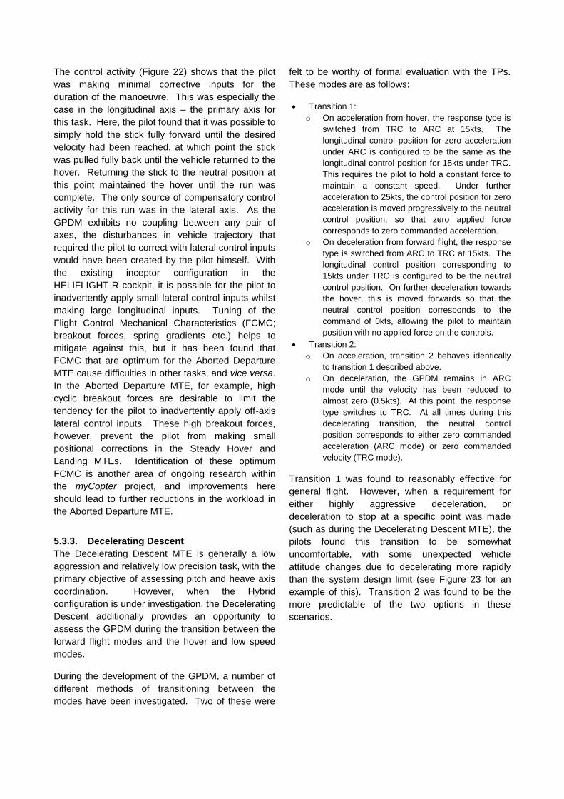
Transition 1 was found to reasonably effective for
general flight. However, when a requirement for
either highly aggressive deceleration, or
deceleration to stop at a specific point was made
(such as during the Decelerating Descent MTE), the
pilots found this transition to be somewhat
uncomfortable, with some unexpected vehicle
attitude changes due to decelerating more rapidly
than the system design limit (see Figure 23 for an
example of this). Transition 2 was found to be the
more predictable of the two options in these
scenarios.

Figure 23: PAV decelerating through Transition 1,
showing uncommanded pitch attitude change
Figure 24 and Figure 25 show that the achieved
level of precision and workload during the
Decelerating Descent MTE with these two transition
methods is relatively similar. All other aspects of the
vehicle configuration were held constant across the
two runs.
Figure 24: Performance Achieved During Decelerating
Descent MTE
Figure 25: Control Activity During Decelerating Descent
MTE
In both cases, the pilot was able to decelerate the
vehicle smoothly to a stop at the target position.
The workload required to achieve this was primarily
focussed on the longitudinal axis – the flight path
angle command response type proved to be
effective at assisting the pilot with maintaining the
target glideslope during the deceleration.
While the time histories (Figure 25) indicate that the
level of control activity was similar for the two
transitions, the improved predictability of Transition 2
was considered to be highly beneficial for this type
of task, leading to the HQR improving from HQR=4
with Transition 1 to HQR=2.5 for Transition 2.
In the case of this MTE, the remaining sources of
compensation were found to lie in judging the
required profiles for the deceleration and descent.
Beyond the flight path vector indicator on the HUD,
the pilot is not currently provided with any additional
cueing regarding distance remaining or the optimum
airspeed at any point on the approach. Provision of
a target speed value may be useful for the pilot in
relieving this aspect of the task.
5.3.4. Landing
The Landing MTE was generally found to pose the
greatest difficulty with all of the GPDM
configurations (Table 7). This was due to the very
high level of precision in lateral and longitudinal
positioning required at the touchdown point. This
led the pilots to apply excessively large control
inputs in an attempt to track the target position.
While the standard Hybrid configuration offered a
significant improvement over the other systems in

this task, the mean HQR was still poorer than for the
other four MTEs.
One possible reason why this task proved to be
more difficult than the other MTEs in the Hybrid
configuration is that the attitude changes that occur
when the pilot commands a new velocity give the
pilot the impression that the vehicle is being
destabilised. This provides the pilot with a reason to
apply additional control inputs in an attempt to
recover stability, when in actual fact these inputs are
not necessary as the vehicle possesses sufficient
stability to adjust itself automatically.
One of the pilots assessed a modified version of the
Hybrid configuration in which the apparent vehicle
pitch and roll attitudes were frozen, meaning the
vehicle remained level throughout the task. All other
vehicle dynamics (rise time of translational rate
responses etc.) remained the same as in the basic
Hybrid configuration. The effect on positional
accuracy and control activity are shown in Figure 26
and Figure 27 below.
Figure 26: Positional Accuracy During Landing MTE
Figure 27: Control Activity During Landing MTE
It is evident that the pilot was able to acquire the
target landing point much more readily when the
vehicle attitudes were frozen. In contrast, there
were a number of positional overshoots, particularly
in the less well cued longitudinal axis (lateral task
cues are located ahead of the pilot; longitudinal task
cues in the pilot’s peripheral vision) when the vehicle
attitudes were free. This can also be seen in the
control activity, with the pilot being required to
correct continually in the longitudinal axis all the way
to the touchdown point with the basic Hybrid
configuration. With the modified configuration, after
initially bringing the vehicle to a hover, the pilot
found it was possible to immediately lower the
collective lever and settle the vehicle onto the
marked touchdown point.
The accuracy of the final touchdown point was
similar for both configurations, but the higher level of
workload lead this pilot to the award of a HQR=3
with the attitudes free to vary. With the attitudes
frozen, this rating improved to HQR=2.
As it is no longer necessary to restrict the rise time
of the translational rate response in order to
minimise the attitude disturbances (as required by
ADS-33E-PRF for example), an interesting
possibility with the vehicle attitudes frozen is that it
becomes possible to significantly increase the rate
at which the vehicle’s velocity responds to the pilot’s
control inputs. Making improvements to the
response rise time would be expected to have the
effect of improving the apparent predictability of the
vehicle, as the velocity will more rapidly follow the
pilot’s commands. Of course, a different method of
generating the translational forces becomes
necessary. The ability to vector the thrust used to lift
the PAV would be required.
6. DISCUSSION
As a general trend, the handling results shown in
Table 7 indicate that the Hybrid configuration will be
significantly more suitable for minimally trained PAV
pilots than either of the ACAH configurations or the
RCAH configuration. At the same time, however,
the results also show that the Hybrid configuration
does not fully meet the target goal of HQR=1 for all
tasks.

As the results presented in the previous Section
show, in the majority of cases the primary reason for
failing to achieve HQR=1 is not the responses of the
vehicle itself, but rather, due to inceptor or cueing
characteristics (HUD symbology) that did not fully
assist the pilot with the task. Therefore, it is
anticipated that the response types encapsulated
within the Hybrid configuration are those required for
PAV pilots. Further tuning of the simulation setup is
expected to elicit improvements in HQRs for the
majority of the tasks.
With the required response types identified, attention
is now turning to the next phase of the research; that
of repeating the tests with other categories of pilot.
It is anticipated that, with the Hybrid configuration,
the majority of pilots across all of the assessed
levels of ability will be capable of completing the
PAV MTEs successfully. In contrast, with the ACAH
and RCAH configurations, it is anticipated that the
majority of the test subjects will struggle to complete
the tasks. Once this task has been completed,
boundaries to permit the prediction of the HQs of
each of the response types (through charts such as
those shown in Section 5.2) will be determined for
the PAV. This will be accomplished by progressively
degrading the rapidity and magnitude of the
responses to the pilot’s controls until the point is
reached that the pilots are no longer able to
satisfactorily complete the tasks. Results from these
phases of work will be reported in the near future.
7. CONCLUDING REMARKS
This paper has presented results from the early
stages of the development of handling qualities
requirements for future Personal Aerial Vehicles
(PAVs), whose pilots will receive a reduced level of
training prior to taking to the air.
A range of vehicle response types have been
assessed, and it has been shown that, for hover and
low speed tasks, a Translational Rate response type
is highly beneficial in both the pitch and roll axes. In
forward flight, other response types become more
suited to the tasks that form the PAV mission. A
‘Hybrid’ configuration has been developed that
confers the optimum response type in all areas of
the flight envelope onto a PAV simulation.
The results presented in this paper show that, while
the target of a Handling Qualities Rating of 1 for all
tasks has not been met, the sources of additional
compensation driving the pilots to the award of
poorer HQRs were typically not the responses of the
vehicle itself. Instead, the drivers lay in other
aspects of the wider simulation, such as the
inceptors used by the pilots to control the vehicle
and the lack of additional cueing provided to the pilot
through Head-Up symbology.
The ongoing myCopter PAV HQs research will
employ pilots of varying levels of basic training to
determine whether the response types identified in
the work to date are indeed suitable for future PAV
pilots, and hence, will validate the proposed
methodology for this process.
8. ACHKNOWLEDGEMENTS
The work reported in this paper is funded by the EC
FP-7 research funding mechanism under grant
agreement no. 266470.
9. REFERENCES
1. Anon., Transport Trends: 2009 Edition, Department for Transport, London, 2009
2. Anon., Energy, Transport and Environment
Indicators, Eurostat Pocketbook, EUROSTAT,
Publications Office of the European Union,
Luxembourg, 2009
3. Anon., Green Paper – Towards a new culture of
urban mobility, COM(2007) 551 final, Commission of
the European Countries, Brussels, September 2007
4. Anon., Out of the Box: Ideas about the Future of Air
Transport. Part 2, European Commission, Brussels,
November 2007
5. Jump, M., et al, myCopter: Enabling Technolofies for
Personal Air Transport Systems, RAeS Conference
“The Future Rotorcraft”, London, UK, June 2011
6. Jump, M., et al, myCopter: Enabling Technologies for
Personal Air Transport Systems – An Early Progress
Report, Proceedings of the 37th European Rotorcraft
Forum, Gallarate, Italy, September 2011
7. Nieuwenhuizen, F.M., et al, myCopter – Enabling
Technologies for Personal Aerial Transportation
Systems, Proceedings of the 3rd
International
Heliworld Conference, Frankfurt, Germany,
November 2011

8. Anon., Handling Qualities Requirements for Military
Rotorcraft, ADS-33E-PRF, USAAMC, March 2000
9. Anon., Flying Qualities of Piloted V/STOL Aircraft,
MIL-F-83300, US DoD, December 1970
10. Anon., Flying Qualities of Piloted Aircraft, MIL-HDBK-
1797, US DoD, December 1997
11. Cooper, G.E. and Harper, Jr. R.P., The Use of Pilot Rating in the Evaluation of Aircraft Handling Qualities, NASA TN-D-5153, April 1969
12. Hart, S.G. and Staveland, L.E., Development of NASA-TLX: Results of Empirical and Theoretical Research, Human Mental Workload (pp. 239-250), Elsevier Science, 1988
13. Roscoe, A.H. and Ellis, G.A., A Subjective Rating Scale for Assessing Pilot Workload in Flight: A Decade of Practical Use, RAE TR-90019, March 1990
14. Carretta, T.R., U.S. Air Force Pilot Selection and Training Methods, Aviation, Space and Environmental Medicine, Vol. 71 No. 9 (pp. 950-956), September 2000
15. Cook, M.V., Flight Dynamics Principles, Arnold, London, 1997
16. Padfield, G.D., Helicopter Flight Dynamics, Second Edition, Blackwell Science, 2007
17. Schönenberg, T., Design of a Conceptual Rotorcraft Model Preparing Investigations of Sidestick Handling Qualities, Proceedings of the 67
th Annual Forum of
the American Helicopter Society, Virginia Beach, VA, USA, May 2011
18. DuVal, R.W., A Real-Time Multi-Body Dynamics Architecture for Rotorcraft Simulation, The Challenge of Realistic Rotorcraft Simulation, RAeS Conference, London, November 2001.
19. Padfield, G.D. and White, M.D. Flight simulation in academia: HELIFLIGHT in its first year of operation at the University of Liverpool, Aeronautical Journal, Vol. 107 No. 1075 (pp. 529-538), 2003
20. White, M.D., et al, Acceptance testing of a rotorcraft flight simulator for research and teaching, Proceedings of the Institution of Mechanical Engineers, Part G: Journal of Aerospace Engineering DOI: 10.1177/0954410012439816, March 2012
21. Teufel, H.J., et al, MPI Motion Simulator: Development and Analysis of a Novel Motion Simulator, in AIAA Modeling and Simulation Technologies Conference and Exhibit, Reston, VA, USA, 2007
22. Anon., BMW’s Full Colour Head Up Display, 2011 [cited 2012, 20
th July], Available from:
http://www.extremetech.com/extreme/102723-could-bmws-full-color-head-up-display-replace-the-instrument-panel
23. Perfect, P., et al, Integrating Predicted and Perceived Fidelity for Flight Simulators, Proceedings of the 36
th
European Rotorcraft Forum, Paris, France, September 2010
24. Timson, E., et al, Pilot Sensitivity to Flight Model Dynamics in Rotorcraft Simulation, Proceedings of the 37
th European Rotorcraft Forum, Gallarate, Italy,
September 2011
25. Padfield, G.D., The Tau of Flight Control, The Aeronautical Journal, Vol. 115 No. 1171 (pp. 521-556), 2011