Embed Size (px)
Citation preview
Applied Catalysis A: General 233 (2002) 77–90
Development of heavy oil hydrocracking catalysts usingamorphous silica-alumina and zeolites as
catalyst supports
M.A. Ali a,∗, T. Tatsumib, T. Masudaca Center for Refining and Petrochemicals, Research Institute, KFUPM, Dhahran, Saudi Arabia
b Division of Materials and Chemical Engineering, Faculty of Engineering, Yokohama National University, Yokohama, Japanc Advanced Catalysts Research Laboratory, Advanced Technology and Research Institute, Japan Petroleum Energy Center,
Kanagawa Science Park, Kanagawa, Japan
Received 12 October 2001; accepted 23 February 2002
Abstract
The overall objective of this research work was to prepare hydrocracking catalysts using amorphous silica-alumina (ASA)supports in combination with USY and�-zeolites. Three supports: namely silica-alumina, USY and�-zeolites were selectedto prepare the extrudates using AP-1 as a binder, while two metal pairs: namely Ni–W and Ni–Mo were loaded on theextrudates through co-impregnation using incipient wetness technique. The catalysts were then calcined at 550◦C for 2 h.The catalysts were tested in a fixed-bed flow reaction system for their activity, using desulfurized vacuum gas oil (DS-VGO)as a feedstock. The catalytic evaluation results of the catalysts showed that�-zeolite alone and in combination with the ASAused in this study, has a potential as a support for developing heavy oil hydrocracking catalysts. A balance of weak and strongacidities of�-zeolite provides control cracking, while high surface area and bigger pores of silica-alumina may be useful forproducing stable hydrocracking and hydrotreating catalysts. © 2002 Elsevier Science B.V. All rights reserved.
Keywords: Silica-alumina;�-Zeolite; USY-zeolite; Hydrocracking; Extrudates; Co-impregnation; Incipient wetness method; DesulfurizedVGO; Acidity; Surface area; Catalytic evaluation; Fixed bed reaction system
1. Introduction
The catalyst used in the hydrocracking processis dual-functional. A hydrocracking catalyst crackshigh-molecular-weight hydrocarbons and hydro-genates the unsaturates that are either formed dur-ing the cracking step or otherwise present in thefeedstock. A typical cracking catalyst consists ofsilica-alumina with base-metal components. Amor-phous silica-alumina (ASA) is viewed as a polymer
∗ Corresponding author. Fax:+966-3-8603586.E-mail address: [email protected] (M.A. Ali).
of alumina on a backbone of silica. Crystalline syn-thetic silica-alumina, known as zeolite, is regarded asa copolymer of alumina and silica with ion-exchangecapacity. In the case of ASA, the activity is attributedto both Lewis- and Bronsted-type acid sites. There isdistribution of acid strength over the catalyst surface.The strongest sites are not the most favorable becausethe slow rate of desorption can retard the catalyticreactions. The most favorable sites are the weak onesthat are sufficiently strong to accomplish the desiredchemical reactions. The reactions that occur in hy-drocracking can be grouped into two broad classes:these are (1) hydrogenation of olefins, aromatic rings,
0926-860X/02/$ – see front matter © 2002 Elsevier Science B.V. All rights reserved.PII: S0926-860X(02)00121-7
78 M.A. Ali et al. / Applied Catalysis A: General 233 (2002) 77–90
sulfur compounds, nitrogen compounds, and oxy-gen compounds and (2) cracking of C–C bonds. Thecracking reactions are slightly endothermic, whilethe hydrogenation reactions are highly exothermic,and the net heat of reaction for the hydrocrackingprocess is thus exothermic. Thus there is a largeadiabatic temperature rise in a commercial hydroc-racker, and a major part of the engineering involvedin the design of a hydrocracker is the control ofthis temperature rise. Excessively high temperaturescan lead to coke deposition and deactivation of thehydrocracking catalyst. Temperature control is ac-complished by the use of cold-recycle-gas quenchinjected at various points between a series of catalystbeds.
Several studies have been conducted using ASAalone and in combination, and comparisons were madewith alumina and zeolites as hydrocracking catalystsupports[1–14]. Some of these studies are describedin what follows. A detailed study has been reportedfor evaluation of hydrodesulfurization (HDS) cata-lysts having NiW, NiMo, and CoMo metal pairs ona number of supports including alumina loaded withPt and Pd. The reactions carried out on dibenzothio-phene (DBT) and substituted DBT compounds showsthat ASA as a support induced a dramatic increasein the H2S tolerance of NiW and thus, showed muchhigher activity than NiMo/ASA and NiMo/aluminacatalysts. Pt/ASA was found to be more active butits sulfur tolerance was much lower than NiW-basedcatalysts[1,2]. Navarro et al.[3] reported their studyon ASA-based transition metal sulfide catalysts, pro-moted by Pt, Ni, Ru and Pd for HDS activity usingDBT. Mo incorporation was responsible for the de-crease in the acidity of the catalyst. The promotersenhanced Mo surface exposure and decrease the re-duction temperature of MoO3. Pd was not found tobe very effective as a promoter due to its poor disper-sion. The HDS activities were found to have the fol-lowing trend: Pt/ASA � PtMo ∼ RuMo > PdMo∼Mo ∼ ASA. Fujiwaka et al.[4] reported a studyto develop a new sulfur-tolerant noble metal catalystwith significantly increased catalytic activity for aro-matic hydrogenation. The screening tests of the vari-ous non-zeolitic noble metal catalysts were carried outwith hydrotreated light cycle oil (LCO)/straight-runlight gas oil (SRLGO) feed containing 32–34 vol.%aromatics and 172–474 ppm sulfur at a temperature of
300◦C, hydrogen pressure of 4.9 MPa, and LHSV of1.5 h−1. The Pt-Pd/SiO2-Al2O3 catalyst was the mosthighly active catalyst for aromatic hydrogenation un-der the conditions applied. The co-existence of Pt withPd on SiO2-Al2O3 remarkably enhanced the catalyticactivity, which depended on the Pd/(Pt+ Pd) weightratio and reached a maximum of about 0.7 Pd/(Pt+Pd)weight ratio. Furthermore, the long-term stability testunder industrial operating conditions demonstrated theexcellent stability of the Pd-Pd/SiO2-Al2O3 catalyst.The results of a study involving alumina show that theinhibiting effect of hydrogen sulfide on sulfur, nitro-gen and aromatics contents is lower at high tempera-ture [5].
A study describing the preparation of a MoO3/Al2O3catalyst revealed that the dispersion of Mo oxide andMo sulfide species increased with the surface area ofthe support and was directly proportional to the HDSactivity of sulfided MoO3/Al2O3. It was demonstratedthat the formation of crystalline MoO3 was stronglycorrelated with the Mo segregation on the outer sur-face of the extrudates[6]. It was suggested that, whena pore volume impregnation or incipient wetness tech-nique is employed, rapid drying at a reduced pressureresults in the segregation of Mo oxides on the outersurface of the extrudates, and accordingly forma-tion of crystalline MoO3. On the other hand, dryingunder static conditions is favorable for a homoge-neous distribution of Mo[7,8]. It was also found thatthe dispersion of Mo oxide species increased as thevolume of the impregnation solution increased. Theincrease in pH (2–8) of the impregnation solution wasfound to reduce the dispersion of Mo oxide species.With the Mo dispersion, the effects of the preparationparameter decreased in the order, surface area of thesupport� drying process> volume of the impreg-nation solution> pH, calcination temperature andatmosphere[9].
The main objective of this study was to prepareheavy oil hydrocracking catalysts using silica-aluminaand zeolite supports, and then to characterize and eval-uate their activity and selectivity performance. The se-quence of work tasks involved in this study consists ofsupport materials selection, characterization, prepara-tion of extrudates with alumina binder and then im-pregnation of metal pairs. The finished catalysts werethen evaluated for their characteristics and catalyticperformance.
M.A. Ali et al. / Applied Catalysis A: General 233 (2002) 77–90 79
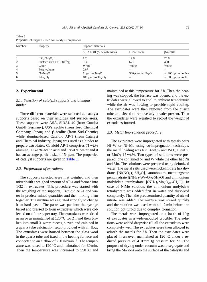
Table 1Properties of supports used for catalysts preparation
Number Property Support materials
SIRAL 40 (Silica-alumina) USY-zeolite �-zeolite
1 SiO2/Al2O3 1.2 14.0 25.02 Surface area BET (m2/g) 514 671 4003 Color White White White4 Pore volume 0.87 – –5 Na/Na2O 7 ppm as Na2O 500 ppm as Na2O < 300 ppmw as Na6 F/Fe2O3 109 ppm as Fe2O3 – < 500 ppmw as F
2. Experimental
2.1. Selection of catalyst supports and aluminabinder
Three different materials were selected as catalystsupports based on their acidities and surface areas.These supports were ASA, SIRAL 40 (from CondeaGmbH Germany), USY zeolite (from Toso ChemicalCompany, Japan) and�-zeolite (from Sud-Chemie)while alumina-based Cataloid AP-1 (from Catalystand Chemical Industry, Japan) was used as a binder toprepare extrudates. Cataloid AP-1 comprises 71 wt.%alumina, 11 wt.% acetic acid and 18 wt.% water and ithas an average particle size of 54�m. The propertiesof catalyst supports are given inTable 1.
2.2. Preparation of extrudates
The supports selected were first weighed and thenmixed with a weighed amount of AP-1 and formed into1/32 in. extrudates. This procedure was started withthe weighing of the supports, Cataloid AP-1 and wa-ter in predetermined quantities and then mixing themtogether. The mixture was agitated strongly to changeit to hard paste. The paste was put into the syringebarrel and pressed to form extrudates which were col-lected on a filter paper tray. The extrudates were driedin an oven maintained at 120◦C for 2 h and then bro-ken into small 3–4 mm pieces, sieved and calcined ina quartz tube calcination setup provided with air flow.The extrudates were housed between the glass woolin the quartz tube and fixed in the heating furnace andconnected to an airflow of 250 ml/min−1. The temper-ature was raised to 120◦C and maintained for 30 min.Then the temperature was increased to 550◦C and
maintained at this temperature for 2 h. Then the heat-ing was stopped, the furnace was opened and the ex-trudates were allowed to cool to ambient temperaturewhile the air was flowing to provide rapid cooling.The extrudates were then removed from the quartztube and sieved to remove any powder present. Thenthe extrudates were weighed to record the weight ofextrudates formed.
2.3. Metal Impregnation procedure
The extrudates were impregnated with metals pairsNi–W or Ni–Mo using co-impregnation technique,the metal loading was NiO 4 wt.% and WO3 15 wt.%or MoO3 15 wt.%. Two types of solutions were pre-pared: one contained Ni and W while the other had Niand Mo. The solutions were prepared using deionizedwater. The metal salts used were nickel nitrate hexahy-drate [Ni(NO3)2·6H2O], ammonium metatungstatepentahydrate [(NH4)6W12O39·5H2O] and ammoniummolybdate tetrahydrate [(NH4)6Mo7O24·4H2O]. Incase of NiMo solution, the ammonium molybdatetetrahydrate was added first in water and dissolvedcompletely. Then the predetermined quantity of nickelnitrate was added; the mixture was stirred quicklyand the solution was used within 1–2 min before thesolution got turbid due to complex formation.
The metals were impregnated on a batch of 10 gof extrudates in a wide-mouthed crucible. The solu-tions were added dropwise till all the extrudates werecompletely wet. The extrudates were then allowed toadsorb the metals for 2 h. Then the extrudates wereplaced in an oven maintained at 120◦C under a re-duced pressure of 410 mmHg pressure for 2 h. Thepurpose of drying under vacuum was to segregate andbring the Mo ions onto the surface of the catalysts and
80 M.A. Ali et al. / Applied Catalysis A: General 233 (2002) 77–90
convert them into MoO3 and thus to provide high hy-drogenation activity on the surface of the catalyst[8].At the end of the drying process, the extrudates wereplaced in a temperature-programmed furnace for cal-cination. The calcination was conducted under the fol-lowing heating program: The temperature was raisedto 120◦C and maintained for 2 h, then the tempera-ture was raised to 550◦C at a heating rate of 2◦C/minand maintained for 2 h at this temperature. Then thefurnace was allowed to cool overnight. The sampleswere kept in airtight glass bottles for characterizationand catalytic evaluation. The weights of the finishedcatalysts obtained after calcination were in the range12.6–13.0 g per batch.
2.4. Characterization of supports and catalysts
The acid properties of the supports and catalystswere determined by temperature-programmed desorp-tion of ammonia. The system was a multitask TPD unit(BELL, Japan). About 0.05 g of each powdered sam-ple was placed in a quartz tube reactor and was pre-treated to 500◦C for 2 h. Ammonia (purity 99.99%)was adsorbed at 100◦C (to avoid excessive physicaladsorption) for 30 min at 100 Torr. Thermal desorp-tion of ammonia was then conducted at 100 Torr usinghelium as a carrier gas and raising the temperature upto 600◦C at a rate of 10◦C/min. The amount of des-orbed ammonia was monitored by a Quadruple Massdetector (Massmate 200). For acidity quantification, apentasil type ZSM-5 zeolite (JRC-Z5-25H) was usedas a standard. This zeolite was white in color, havingSiO2/Al2O3 molar ratio of 25, a BET surface area of300 m2/g and containing less than 100 ppm Na. Thecatalysts were characterized for their surface area andporosity using a nitrogen adsorption method accord-ing to ASTM D 3663 using NOVA 1200 from Quan-tachrome.
2.5. Catalysts performance evaluation in afixed-bed flow reaction system
The evaluation of hydrocracking catalysts was car-ried out under variable operating conditions of temper-ature and pressure in a fixed-bed flow reaction system.The feedstock used for the catalyst evaluation exper-iments was desulfurized vacuum gas oil (DS-VGO)
obtained from a refinery in Japan. Since the DS-VGOwas solid at room temperature, it was heated to 50◦Cto make it a homogenous liquid before use. The flowreactor evaluation of the catalysts was conducted in apacked-bed reaction system having multiple reactorsfor simultaneous evaluation of five catalysts. The reac-tion system was provided with a 10 cm3 tubular reac-tor, a sand bath heater for reaction temperature and thelong glass burettes in the feed tank were attached tothe feed pump. The catalysts were presulfided in situbefore the activity evaluation tests were performed.The hydrocracking reaction conditions selected wereas follows: pressure 100 kg/cm2 (1400 psi), hydrogenflow rate of NL/h, hydrogen gas to hydrocarbon ratioof 5900 scfb, operating temperature range from 380to 410◦C, feed rate of 10 ml/h and liquid hour spacevelocity of 1.0. DS-VGO was utilized as feedstock forthe evaluation of the catalysts.
Ten millilitre, each of three different catalysts weremeasured in three 10 ml graduated cylinders with tap-ping and the weights of the catalysts were recorded.These three catalysts were loaded in three separatereactors with glass wool plugging and aluminumpacking rings at both ends of the reactors. Thesereactors were installed in a sand bath heater. Afterinstallation of the reactors to the unit, reactors werepressurized up to 10 Mpa hydrogen pressure for leaktest and kept overnight to detect any leak present. Thecatalysts was then sulfided using H2S in H2 mixtureat 400◦C for 2 h. After presulfiding, the temperaturewas lowered to 200◦C and then the H2S in H2 mixturewas replaced by pure hydrogen and the reactors werepressurized up to 10 Mpa. Then, DS-VGO feedstockand hydrogen gas flow rates were set to obtain a spacevelocity of two and a H2 gas/ hydrocarbon feed ratioof 5900 scfb. After the operation became stabilized,temperature was gradually raised to three reactiontemperatures and the conditions were allowed to sta-bilized. At each reaction temperature, the samples ofgas and liquid were collected. Liquid samples wereanalyzed for simulated distillation and sulfur and ni-trogen contents, while the gas samples were analyzedfor gaseous components present. At the end of eachcatalyst run that lasted for 30 h, the run was stoppedand spent catalysts were collected. The cracking activ-ity of the catalysts in terms of percent conversion andpercent hydrogenation (HDS and HDN) was calcu-lated. The percent conversion was defined as the sum
M.A. Ali et al. / Applied Catalysis A: General 233 (2002) 77–90 81
of the amount of gas and liquid products produced(gasoline+kerosene+gas oil fraction) while the HDSand HDN activities were calculated by determining thesulfur and nitrogen contents of the feed and reactionproducts.
3. Characterization of DS-VGO feed andhydrocracking reaction products
3.1. Elemental analysis
The DS-VGO feed and hydrocracking reactionproducts were analyzed for their sulfur and nitrogencontents using an elemental analyzer Model ANTEK7000 provided with an ANTEK 735 Syringe drive.The lower detection limit of this analyzer was 10 ppmfor total sulfur and nitrogen content.
3.2. Boiling range distribution
The boiling range distribution of DS-VGO feed-stock and hydrocracking reaction products was deter-mined by a simulated distillation analyzer using theASTM method D 2887. The system consisted of aShimadzu gas chromatograph equipped with an auto-matic sampler, a flame ionization detector (FID) anda packed column (3× 1000 mm) silicone OV-1 Chro-mosorb W 60/80 AW-DMCS (Shimadzu). The gaschromatograph was calibrated by analyzing a mixtureof normal paraffins with known boiling points.
3.3. Gas composition analysis
The compositions of the gas products were deter-mined by gas chromatography. The system consistedof a Shimadzu gas chromatograph equipped with asampling loop and two columns (from Shimadzu):Sunpak-S for H2S separation from hydrocarbon gasesand Porapak-Q for hydrocarbon gases separation. Thedetection of the separated components was performedusing a flame ionization detector FID for hydrocar-bon gases and a thermal conductivity detector for H2Sdetermination. The hydrogen contents of the gas sam-ples were determined by differences. The gas chro-matograph was calibrated by analyzing a mixture ofhydrocarbon gases and H2S.
Table 2Properties of DS-VGO feedstock
Properties Results
Physical property resultsColor Greenish dark
brownAppearance Solid at room
temperatureDensity (15◦C, g/cm3) 0.890
SIMDIST distillation fractions (temperature,◦C)Kerosene (150–250◦C) (%) 0.0Gas oil (250–343◦C) (%) 8.9Vacuum gas oil (343–520◦C) (%) 84.7Vacuum residue (> 520◦C) (%) 6.4
Elemental analysis resultsSulfur content (wt.%) 0.289Nitrogen content (wt.%) 0.028
4. Results and discussion
4.1. Characterization
4.1.1. Feedstock characterizationThe properties of DS-VGO feedstock are given in
Table 2.
4.2. Catalysts characterization
4.2.1. Surface area and porosityThe compositions of the prepared catalysts are given
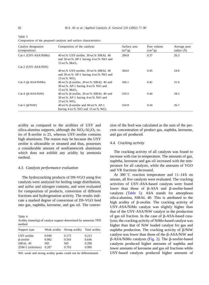
in Table 3along with their surface characteristics andporosity in terms of BET surface area, pore volumeand average pore radius. The surface area and poreradius and pore volume values obtained are of thecatalysts containing zeolite, silica-alumina and binderand thus represent the properties of the mixed sup-ports. The catalysts loaded with Mo showed lowersurface area compared to those having W loadings.Similarly, catalysts prepared with�-zeolite showedlower surface area as compared to those having USYzeolites.
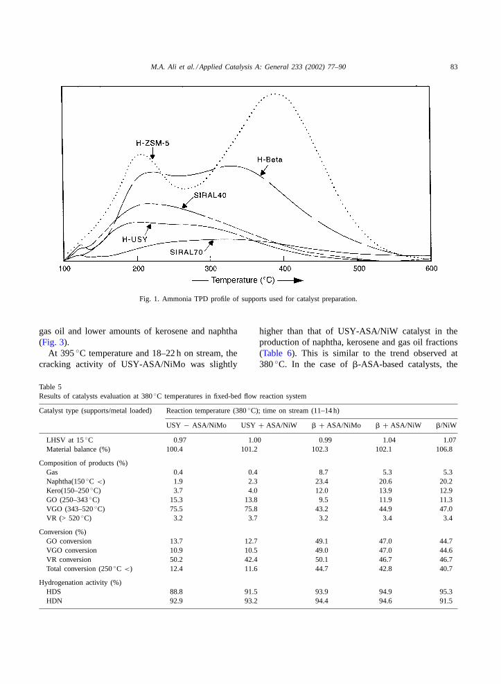
4.2.2. Acidity by ammonia TPD methodThe supports were characterized for their acidi-
ties using ammonia–TPD method. The results aregiven in Table 4 and the TPD profile is given inFig. 1. It was found that�-zeolite possesses higher
82 M.A. Ali et al. / Applied Catalysis A: General 233 (2002) 77–90
Table 3Composition of the prepared catalysts and surface characteristics
Catalyst designation(composition)
Composition of the catalysts Surface area(m2/g)
Pore volume(cm3/g)
Average poreradius (Å)
Cat-1 (USY-ASA/NiMo) 40 wt.% USY-zeolite, 30 wt.% SIRAL 40and 30 wt.% AP-1 having 4 wt.% NiO and15 wt.% MoO3
284.8 0.37 26.3
Cat-2 (USY-ASA/NiW)40 wt.% USY-zeolite, 30 wt.% SIRAL 40and 30 wt.% AP-1 having 4 wt.% NiO and15 wt.% WO3
364.0 0.45 24.8
Cat-3 (�-ASA/NiMo) 40 wt.% �-zeolite, 30 wt.% SIRAL 40 and30 wt.% AP-1 having 4 wt.% NiO and15 wt.% MoO3
266.1 0.42 31.6
Cat-4 (�-ASA/NiW) 40 wt.% �-zeolite, 30 wt.% SIRAL 40 and30 wt.% AP-1 having 4 wt.% NiO and15 wt.% WO3
310.5 0.44 28.5
Cat-5 (�/NiW) 40 wt.% �-zeolite and 60 wt.% AP-1having 4 wt.% NiO and 15 wt.% WO3
254.9 0.34 26.7
acidity as compared to the acidities of USY andsilica-alumina supports, although the SiO2/Al2O3 ra-tio of ß-zeolite is 25, whereas USY-zeolite containshigh aluminum. The reason may be because the USYzeolite is ultrastable or steamed and thus, possessesa considerable amount of nonframework aluminumwhich does not exhibit any acidity by ammoniamethod.
4.3. Catalysts performance evaluation
The hydrocracking products of DS-VGO using fivecatalysts were analyzed for boiling range distribution,and sulfur and nitrogen contents, and were evaluatedfor composition of products, conversion of differentfractions and hydrogenation activity. The results indi-cate a marked degree of conversion of DS-VGO feedinto gas, naphtha, kerosene, and gas oil. The conver-
Table 4Acidity (mmol/g) of catalyst support determined by ammonia TPDmethod
Support type Weak acidity Strong acidity Total acidity
USY-zeolite 0.040 0.173 0.213�-zeolite 0.082 0.564 0.646SIRAL 40 ND ND 0.298ZSM-5 (reference) 0.287 0.703 0.990
ND: weak and strong acidity peaks could not be differentiated.
sion of the feed was calculated as the sum of the per-cent concentration of product gas, naphtha, kerosene,and gas oil produced.
4.4. Cracking activity
The cracking activity of all catalysts was found toincrease with rise in temperature. The amounts of gas,naphtha, kerosene and gas oil increased with the tem-perature for all catalysts, while the amounts of VGOand VR fractions decreased.
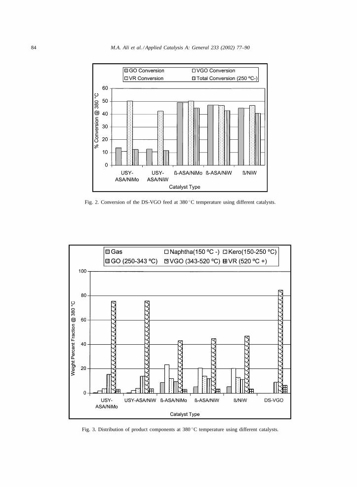
At 380◦C reaction temperature and 11–14 h onstream, all five catalysts were evaluated. The crackingactivities of USY-ASA-based catalysts were foundlower than those of�-ASA and �-zeolite-basedcatalysts (Table 5). ASA stands for amorphoussilica-alumina, SIRAL 40. This is attributed to thehigh acidity of �-zeolite. The cracking activity ofUSY-ASA/NiMo catalyst was slightly higher thanthat of the USY-ASA/NiW catalyst in the productionof gas oil fraction. In the case of�-ASA-based cata-lysts, the cracking activity of NiMo-based catalyst washigher than that of NiW loaded catalyst for gas andnaphtha production. The cracking activity of�/NiWcatalyst was lower than those of the�-ASA/NiW and�-ASA/NiMo catalysts (Fig. 2). The �-zeolite-basedcatalysts produced higher amounts of naphtha andlower amounts of kerosene and gas oil fractions whileUSY-based catalysts produced higher amounts of
M.A. Ali et al. / Applied Catalysis A: General 233 (2002) 77–90 83
Fig. 1. Ammonia TPD profile of supports used for catalyst preparation.
gas oil and lower amounts of kerosene and naphtha(Fig. 3).
At 395◦C temperature and 18–22 h on stream, thecracking activity of USY-ASA/NiMo was slightly
Table 5Results of catalysts evaluation at 380◦C temperatures in fixed-bed flow reaction system
Catalyst type (supports/metal loaded) Reaction temperature (380◦C); time on stream (11–14 h)
USY − ASA/NiMo USY + ASA/NiW � + ASA/NiMo � + ASA/NiW �/NiW
LHSV at 15◦C 0.97 1.00 0.99 1.04 1.07Material balance (%) 100.4 101.2 102.3 102.1 106.8
Composition of products (%)Gas 0.4 0.4 8.7 5.3 5.3Naphtha(150◦C <) 1.9 2.3 23.4 20.6 20.2Kero(150–250◦C) 3.7 4.0 12.0 13.9 12.9GO (250–343◦C) 15.3 13.8 9.5 11.9 11.3VGO (343–520◦C) 75.5 75.8 43.2 44.9 47.0VR (> 520◦C) 3.2 3.7 3.2 3.4 3.4
Conversion (%)GO conversion 13.7 12.7 49.1 47.0 44.7VGO conversion 10.9 10.5 49.0 47.0 44.6VR conversion 50.2 42.4 50.1 46.7 46.7Total conversion (250◦C <) 12.4 11.6 44.7 42.8 40.7
Hydrogenation activity (%)HDS 88.8 91.5 93.9 94.9 95.3HDN 92.9 93.2 94.4 94.6 91.5
higher than that of USY-ASA/NiW catalyst in theproduction of naphtha, kerosene and gas oil fractions(Table 6). This is similar to the trend observed at380◦C. In the case of�-ASA-based catalysts, the
84 M.A. Ali et al. / Applied Catalysis A: General 233 (2002) 77–90
Fig. 2. Conversion of the DS-VGO feed at 380◦C temperature using different catalysts.
Fig. 3. Distribution of product components at 380◦C temperature using different catalysts.
M.A. Ali et al. / Applied Catalysis A: General 233 (2002) 77–90 85
Table 6Results of catalysts evaluation at 395◦C temperatures in fixed-bed flow reaction system
Catalyst type (supports/metal loaded) Reaction temperature (395◦C); time on stream (18–22 h)
USY − ASA/NiMo USY + ASA/NiW � + ASA/NiMo � + ASA/NiW �/NiW
LHSV at 15◦C 0.96 1.05 0.98 1.04 0.88Material balance (%) 100.5 91.4 96.6 94.8 92.5
Composition of products (%)Gas 0.9 0.8 9.4 8.2 8.8Naphtha(150◦C <) 4.7 4.1 34.1 40.4 45.5Kero(150–250◦C) 8.3 7.2 15.5 17.7 17.0GO (250–343◦C) 16.5 16.0 9.3 8.4 6.6VGO (343–520◦C) 66.6 68.6 30.2 23.7 21.1VR (> 520◦C) 3.0 3.4 1.5 1.7 1.0
Conversion (%)GO conversion 23.7 21.0 65.2 72.2 75.8VGO conversion 21.4 19.0 64.4 72.0 75.1VR conversion 53.6 47.3 75.9 74.2 84.3Total conversion (> 250◦C) 21.6 19.1 59.4 65.8 69.0
Hydrogenation activity (%)HDS 93.6 93.9 97.2 97.7 98.5HDN >96.0 95.7 >96.0 >96.0 >96.0
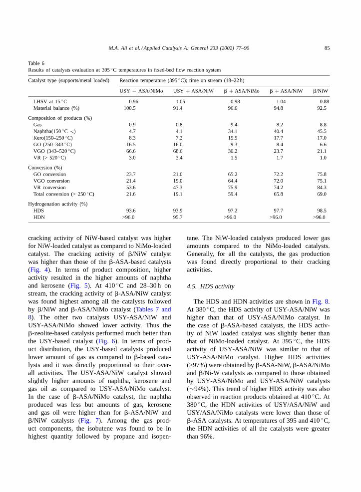
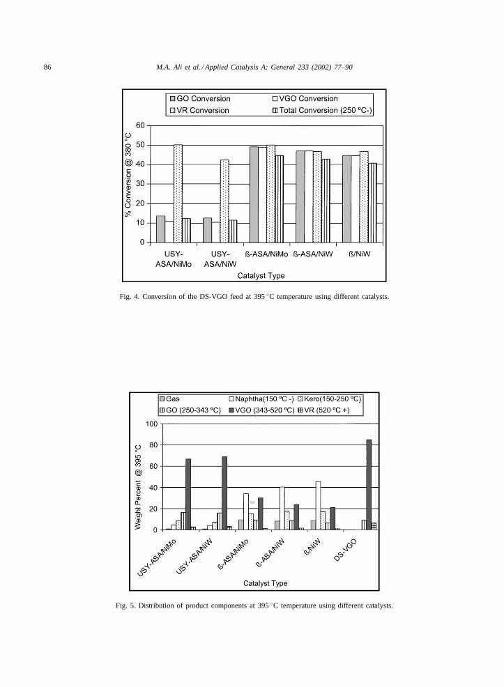
cracking activity of NiW-based catalyst was higherfor NiW-loaded catalyst as compared to NiMo-loadedcatalyst. The cracking activity of�/NiW catalystwas higher than those of the�-ASA-based catalysts(Fig. 4). In terms of product composition, higheractivity resulted in the higher amounts of naphthaand kerosene (Fig. 5). At 410◦C and 28–30 h onstream, the cracking activity of�-ASA/NiW catalystwas found highest among all the catalysts followedby �/NiW and �-ASA/NiMo catalyst (Tables 7 and8). The other two catalysts USY-ASA/NiW andUSY-ASA/NiMo showed lower activity. Thus the�-zeolite-based catalysts performed much better thanthe USY-based catalyst (Fig. 6). In terms of prod-uct distribution, the USY-based catalysts producedlower amount of gas as compared to�-based cata-lysts and it was directly proportional to their over-all activities. The USY-ASA/NiW catalyst showedslightly higher amounts of naphtha, kerosene andgas oil as compared to USY-ASA/NiMo catalyst.In the case of�-ASA/NiMo catalyst, the naphthaproduced was less but amounts of gas, keroseneand gas oil were higher than for�-ASA/NiW and�/NiW catalysts (Fig. 7). Among the gas prod-uct components, the isobutene was found to be inhighest quantity followed by propane and isopen-
tane. The NiW-loaded catalysts produced lower gasamounts compared to the NiMo-loaded catalysts.Generally, for all the catalysts, the gas productionwas found directly proportional to their crackingactivities.
4.5. HDS activity
The HDS and HDN activities are shown inFig. 8.At 380◦C, the HDS activity of USY-ASA/NiW washigher than that of USY-ASA/NiMo catalyst. Inthe case of�-ASA-based catalysts, the HDS activ-ity of NiW loaded catalyst was slightly better thanthat of NiMo-loaded catalyst. At 395◦C, the HDSactivity of USY-ASA/NiW was similar to that ofUSY-ASA/NiMo catalyst. Higher HDS activities(>97%) were obtained by�-ASA-NiW, �-ASA/NiMoand�/Ni-W catalysts as compared to those obtainedby USY-ASA/NiMo and USY-ASA/NiW catalysts(∼94%). This trend of higher HDS activity was alsoobserved in reaction products obtained at 410◦C. At380◦C, the HDN activities of USY/ASA/NiW andUSY/ASA/NiMo catalysts were lower than those of�-ASA catalysts. At temperatures of 395 and 410◦C,the HDN activities of all the catalysts were greaterthan 96%.
86 M.A. Ali et al. / Applied Catalysis A: General 233 (2002) 77–90
Fig. 4. Conversion of the DS-VGO feed at 395◦C temperature using different catalysts.
Fig. 5. Distribution of product components at 395◦C temperature using different catalysts.

M.A. Ali et al. / Applied Catalysis A: General 233 (2002) 77–90 87
Table 7Results of catalysts evaluation at 400 and 410◦C temperature in fixed-bed flow reaction system
Catalyst type(Supports/metal loaded)
Reaction temperature (410◦C); time onstream (26–28 h)
Reaction temperature (400◦C); time onstream (24–26 h)
USY − ASA/NiMo USY + ASA/NiW � + ASA/NiMo � + ASA/NiW �/NiW
LHSV at 15◦C 1.11 1.05 1.05 1.13 0.98Material balance (%) 98.4 97.6 92.0 91.1 94.5
Composition of products (%)Gas 1.8 1.6 11.5 11.1 8.6Naphtha(< 150◦C) 10.3 10.4 41.1 46.4 46.5Kero(150–250◦C) 16.4 17.2 17.7 17.4 17.5GO (250–343◦C) 19.4 20.2 9.0 7.6 6.9VGO (343–520◦C) 50.1 48.6 19.8 16.4 19.5VR (520◦C >) 2.0 2.0 0.9 1.0 1.0
Conversion (%)GO conversion 42.9 44.5 77.3 80.9 77.5VGO conversion 40.9 42.6 76.6 80.6 77.0VR conversion 69.3 69.3 86.2 84.7 84.3Total conversion (< 250◦C) 39.1 40.5 70.4 73.7 70.6
Hydrogenation activity (%)HDS 94.5 95.8 97.5 97.7 98.0HDN >96.0 >96.0 >96.0 >96.0 >96.0
Table 8Results of catalysts evaluation at 410◦C temperature in fixed-bed flow reaction system
Catalyst type (Supports/metal loaded) Reaction temperature (410◦C); time on stream (28–30 h)
USY − ASA/NiMo USY + ASA/NiW � + ASA/NiMo � + ASA/NiW �/NiW
LHSV at 15◦C 1.05 1.02 1.09 1.01 1.06Material balance (%) 98.8 99.1 97.4 100.6 93.6
Composition of products (%)Gas 2.2 1.9 15.0 16.3 10.4Naphtha(< 150◦C) 12.2 12.7 51.1 62.1 61.2Kero(150–250◦C) 17.7 19.0 15.5 13.7 16.3GO (250–343◦C) 19.6 20.6 6.0 3.0 4.6VGO (343–520◦C) 46.4 44.3 12.5 4.9 7.4VR (520◦C >) 1.9 1.5 0.0 0.0 0.1
Conversion (%)GO conversion 47.0 49.7 86.3 94.7 91.7VGO conversion 45.2 47.6 85.2 94.3 91.2VR conversion 71.0 77.0 100.0 100.0 98.6Total conversion (< 250◦C) 42.8 45.3 78.6 86.2 83.6
Hydrogenation activity (%)HDS 93.8 95.7 97.7 98.2 96.9HDN >96.0 >96.0 >96.0 >96.0 >96.0

88 M.A. Ali et al. / Applied Catalysis A: General 233 (2002) 77–90
Fig. 6. Distribution of product components at 410◦C temperature using different catalysts.
Fig. 7. Conversion of the DS-VGO feed at 410◦C temperature using different catalysts.

M.A. Ali et al. / Applied Catalysis A: General 233 (2002) 77–90 89
Fig. 8. HDS and HDN activity of different catalysts at 380◦C temperature.
5. Conclusions
Five catalyst recipes were prepared using silica-alumina and zeolite supports. The catalytic evaluationresults of the catalysts showed that�-zeolite aloneand in combination with ASA used in this study, hasa potential as a support for developing hydrocrack-ing catalysts for heavy oil hydrocracking. Among thecatalysts, NiW-loaded catalysts showed more hydro-cracking and HDS activity compared to NiMo-loadedcatalysts and produced more lighter naphtha. Simi-larly, �-zeolite supported catalysts showed higher hy-drocracking and HDS activity than USY supportedcatalysts. The difference in the activity of catalystshaving different supports and metals was more pro-nounced at 380◦C temperature as compared to 395and 410◦C. The HDN activity of�-zeolite supportedcatalysts at 380◦C was found higher than those ofUSY containing catalysts. However, the HDN activitywas similar at 395 and 410◦C and was 96% for all cat-alysts regardless of their support and metal pair types.
The catalytic evaluation results of the catalystsshowed that�-zeolite either alone or in combinationwith (ASA) used in this study has a potential forusing as a support for developing hydrocracking cat-alysts for heavy oil hydrocracking. The high surface
area and bigger pores of silica-alumina may be usefulfor producing stable hydrocracking and hydrotreatingcatalysts.
Acknowledgements
The authors acknowledge the support of the Re-search Institute, King Fahd University Of Petroleumand Minerals, Dhahran, Saudi Arabia. The authors ap-preciate the support of the JPI and JPEC for this studythat was conducted at Yokohama National University(YNU) and at the Advanced Catalysts Research Lab-oratory, Japan Petroleum Energy Center, AdvancedTechnology and Research Institute at Kanagawa Sci-ence Park (KSP), Japan. Appreciation is due to theYNU and KSP personnel involved in conducting thisresearch work.
References
[1] W.R.A.M. Robinson, J.A.R. van Veen, V.H.J. de Beer, R.A.van Santen, Fuel Proc. Technol. 61 (1999) 89.
[2] W.R.A.M. Robinson, J.A.R. van Veen, V.H.J. de Beer, R.A.van Santen, Fuel Proc. Technol. 61 (1999) 103.

90 M.A. Ali et al. / Applied Catalysis A: General 233 (2002) 77–90
[3] M. Navarro, B. pawelec, J.L.G. Fierro, P.T. Vasudevan, Appl.Catal. A: Gen. 148 (1996) 23.
[4] T. Fujiwaka, K. Idei, T. Ebihara, H. Mizuguchi, K. Usui,Appl. Catal. A: Gen. 192 (2000) 253.
[5] J. Ancheyta-Juarez, E. Aguilar-Rodrıguezab, D. Salazar-Sotelo, G. Marroquın-Sáncheza, G. Quiroz-Sosaa, M. Leiva-Nuncio, Appl. Catal. A: Gen. 183 (1999) 265.
[6] Y. Okamoto, et al., Appl. Catal. A: Gen. 170 (1998) 315.[7] Y. Okamoto, et al., Appl. Catal. A: Gen. 170 (1998) 329.[8] Y. Okamoto, et al., Appl. Catal. A: Gen. 170 (1998) 343.[9] Y. Okamoto, et al., Appl. Catal. A: Gen. 170 (1998) 359.
[10] V. Calemma, S. Peratello, C. Perego, Appl. Catal. A: Gen.190 (2000) 207.
[11] B. Egia, J.F. Cambra, P.L. Arias, M.B. Güemez, J.A.Legarreta, B. Pawelec, J.L.G. Fierro, Appl. Catal. A: Gen.169 (1998) 37.
[12] T. Tatsumi, M. Taniguchi, S. Yasuda, Y. Ishii, T. Murata, M.Hidai, Appl. Catal. A: Gen. 139 (1996) L5.
[13] M. Taniguchi, D. Imamura, H. Ishige, Y. Ishii, T. Murata, M.Hidai, T. Tatsumi, J. Catal. 187 (1999) 139.
[14] M. Taniguchi, Y. Yasuda, Y. Ishii, T. Murata, M. Hidai, T.Tatsumi, Stud. Surf. Sci. Catal. 10 (1996) 107.