Embed Size (px)
Citation preview
DISTRIBUTION STATEMENT A. Approved for public release; distribution is unlimited
Development of High Temperature Insulated Bus Pipe (HTIBP)
for High Energy Naval Systems
A Path Forward Plan – Update HIGH TEMPERATURE INSULATED BUS PIPE GAS
FLAME CIRCUIT INTEGRITY TESTING
Rick Worth/NAVSSES, Code 982
December 2, 2014
Background:
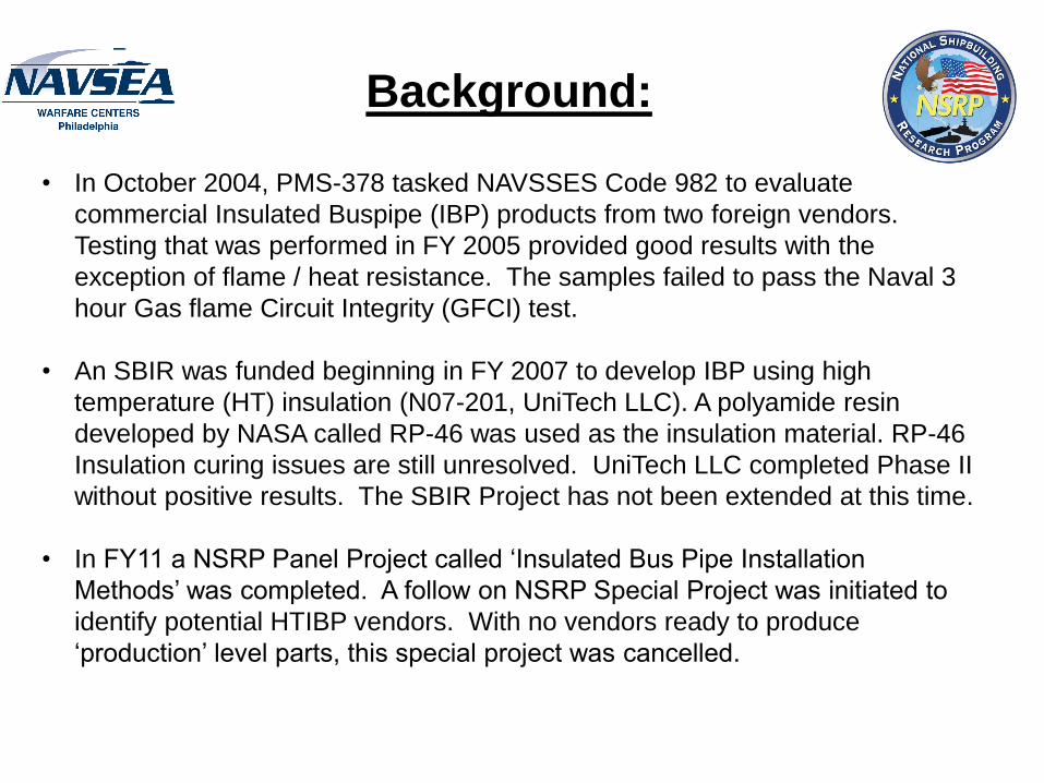
• In October 2004, PMS-378 tasked NAVSSES Code 982 to evaluate
commercial Insulated Buspipe (IBP) products from two foreign vendors.
Testing that was performed in FY 2005 provided good results with the
exception of flame / heat resistance. The samples failed to pass the Naval 3
hour Gas flame Circuit Integrity (GFCI) test.
• An SBIR was funded beginning in FY 2007 to develop IBP using high
temperature (HT) insulation (N07-201, UniTech LLC). A polyamide resin
developed by NASA called RP-46 was used as the insulation material. RP-46
Insulation curing issues are still unresolved. UniTech LLC completed Phase II
without positive results. The SBIR Project has not been extended at this time.
• In FY11 a NSRP Panel Project called ‘Insulated Bus Pipe Installation
Methods’ was completed. A follow on NSRP Special Project was initiated to
identify potential HTIBP vendors. With no vendors ready to produce
‘production’ level parts, this special project was cancelled.
Background (cont):
• Subsequently in early 2014, ONR 33 and NSRP provided NAVSSES, Code
982 funding to identify and investigate other vendor’s products and to perform
testing on any promising products identified.
• A Russian company (with a manufacturing facility underway in New Orleans)
called Telefen GmbH has a 3 phase IBP product that uses high temperature
insulation. They also manufacture a single phase IBP, but is not presently high
temperature rated.
• Telefen offered to ship a high temperature rated 3 phase IBP to the Navy for 3
hour GFCI testing. The plan was that if the 3 phase product successfully
passed the 3 hour GFCI test, that Telefen would develop a single phase high
temperature IBP sample for additional GFCI testing
• Telefen shipped the sample to NAVSSES in August 2014. Aero Nav labs in
College Point, NY was contracted by National Ship Research Program
(NSRP) to perform Navy 3 hour GFCI testing on the 3 phase Telefen provided
sample. The sample was shipped to Aero Nav in October 2014. The 3 hour
GFCI test was scheduled to be performed on November 18th.
Approach:
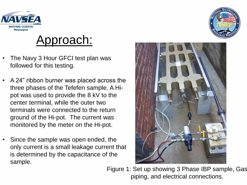
• The Navy 3 Hour GFCI test plan was
followed for this testing.
• A 24” ribbon burner was placed across the
three phases of the Tefefen sample. A Hi-
pot was used to provide the 8 kV to the
center terminal, while the outer two
terminals were connected to the return
ground of the Hi-pot. The current was
monitored by the meter on the Hi-pot.
• Since the sample was open ended, the
only current is a small leakage current that
is determined by the capacitance of the
sample.
Figure 1: Set up showing 3 Phase IBP sample, Gas
piping, and electrical connections.
Test Underway:
• When the setup was complete, the gas flame was ignited and set as described
in the test plan. Then the Hi-pot was energized and set to 8 kV. The initial
leakage current was 3.6 mA. If the leakage current exceeds 250 mA, the sample
is considered to have failed the test.
• The time was 1350 when the flame and voltage were applied.
• Within a few minutes, white smoke and a yellow flame appeared on the sample
just above the gas burner. A call to Telefen confirmed our suspicion that a layer
of varnish had been applied to the sample and it was burning off. After about 10
more minutes the smoke and yellow flame had dissipated.
• The leakage current was monitored every 15 minutes. It remained constant at
3.6 mA. At 1650, the test was complete with the sample passing. Photos of the
test are presented below:

Photos of Test
Figure 2: Hi-Pot used to provide 8 kV to sample
Figure 3: Yellow flame due to surface varnish burning off.

Photos of Test (cont):
Figure 4: Yellow Flame and Smoke dissipated after a 30 minutes
Figure 5: Hi-Pot set at 8 kV and leakage current holding steady at 3.6 mA
Summary:
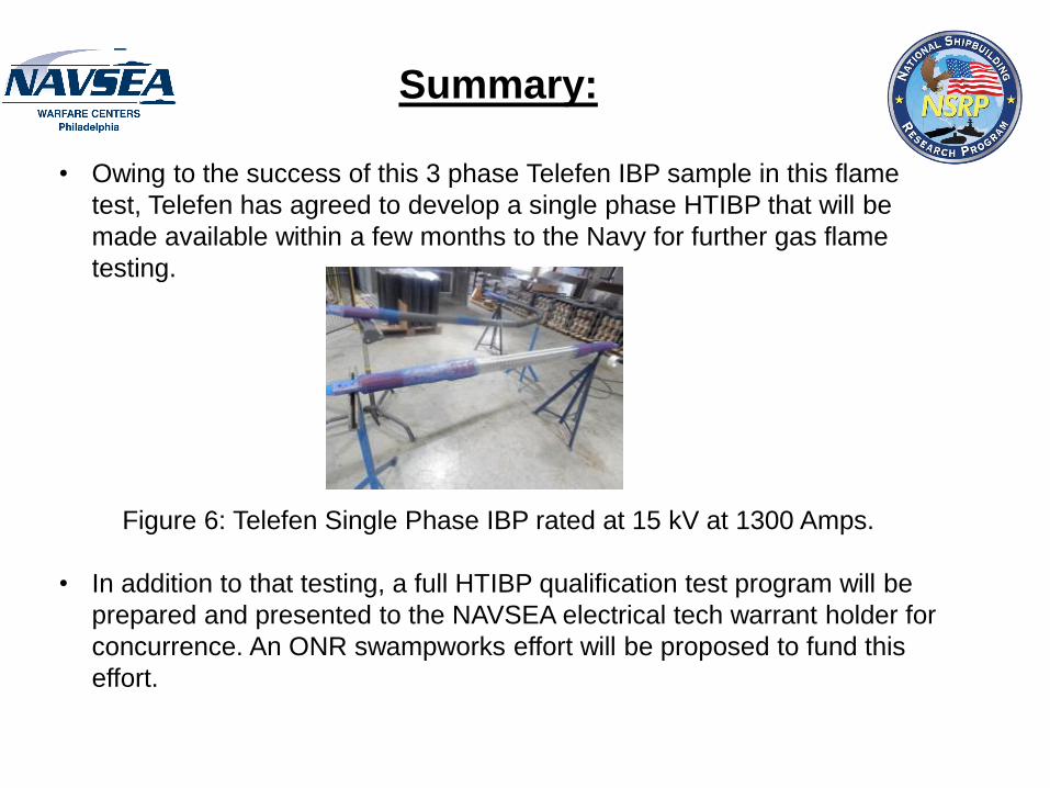
• Owing to the success of this 3 phase Telefen IBP sample in this flame
test, Telefen has agreed to develop a single phase HTIBP that will be
made available within a few months to the Navy for further gas flame
testing.
Figure 6: Telefen Single Phase IBP rated at 15 kV at 1300 Amps.
• In addition to that testing, a full HTIBP qualification test program will be
prepared and presented to the NAVSEA electrical tech warrant holder for
concurrence. An ONR swampworks effort will be proposed to fund this
effort.

BACKUP SLIDES
Electrical Energy Demands of Future
Combatants • Established trend of ever increasing electrical power
requirements – Hybrid Ship Propulsion utilizes electrical energy as a
conversion medium
– Directed Energy Weapons utilize electrical power vice explosive propellants
– Increased surveillance capability needs result in higher electrical power requirements
– EMALS allows for sophisticated launch control, uses electrical power vice steam
Increased Electrical Requirements result in challenges to distribute Electrical Power
Challenges IBP Resolves
• Power Cables become large and unwieldy
– High Power circuits require multiple conductors
– Dangerous and time consuming to install / connect
– Bend radii are large, compartments are dedicated to changing direction
• Insulated Bus Pipe
– Accepted to reduce weight and space claims
– Can be installed as part of blocks/modules and then connected
– Turns are prefabricated, thus small radii are possible

US Navy History of IBP • Testing performed in FY 2005 provided good results with the
exception of flame / heat resistance
• An SBIR was funded beginning in FY 2007 to develop high temperature insulation (N07-201, UniTech LLC)
– Insulation curing issues are still unresolved
– Phase II complete without positive result
– Project was not extended at this time
• NSRP Panel Project FY 2011;
– ‘Insulated Buss Pipe Installation Methods’
• NSRP Special Project to identify potential HTIBP vendors
– Cancelled, no vendors ready to produce ‘production’ level parts
• There has been consistent and growing interest by the Shipyards to pursue IBP to address both schedule risk and cost issues
US Navy IBP Current • ONR Project is currently being funded to advance HTIBP
development. NSRP providing an additional $38 K for this effort
• IEEE is currently working on standards for marine application (1580.1), many shipbuilders are participating
• Ritz Transformer has developed and flame tested their version of HTIBP. Teamed with RTC Electro Corp. (Tefelen USA)
– Test not correctly performed, they are seeking funding to perform ‘Navy Test’
– German Company with US production facilities in Lavonia, GA
– RTC Electro has separated from Ritz Transformer, and is opening a US facility in New Orleans under the name: Tefelen www.Tefelen.com
– Tefelen shipped HTIBP samples to NAVSSES/Philly for Gas Flame Test
• NAVSSES and PMS 320 developing preliminary documentation for a proposed Swampworks Effort to take HTIBP from TRL 3/4 to 7/8

Ritz Transformer Corp. Developed HTIBP Sample
Flame Test
Ceramic Coated Sample performed successfully for 4 hours energized at 24 kV.
Test location was Ritz facility in Kirchaich, Germany on 6 Nov 2013

Initial Recommended Path to Implementation (Part 1 of proposed
Swampworks Program)
• Perform Navy 3 Hour Gas Flame Circuit Integrity Test on Telefen HTIBP sample
• AeroNav Labs under contract to perform 3 hour GFCI test in Oct 2014 - 6 Month Effort
• Material Qualification
• Test requirements proposed by NAVSSES for review and approval by SEA 05Z TWH (G. Blalock) – 1 Year Effort
• LBES installation / test • DDG-1000 application proposed between switchboard and harmonic
filters of AIM motor. – 6 Month Effort
• Final qualification test would be DDG 1002

Parallel Part 2 Swampworks Effort to HTIBP Qualification
Testing • Rigorous Business Case for US Navy applications
– Design approach is different – Material cost is likely higher
• Connection Techniques need to be investigated and proven Navy Ship Board Ready
• Design and build practices need to be established • Specifications and installation methods need to be matured
– Develop requirements for DC systems in parallel
• Need to establish standard parts approach – Avoid unique parts for each builder / ship class
• Need to characterize maintenance requirements • Limited modifications by shipbuilder • Need to mature manufacturing base

Potential Stakeholders for HTIBP
• NAVSEA 05Z Technical Warrant
• Electric Ships Office (AC and DC)
• HII Ingalls shipbuilding – LPD/LHD (7.7 kV AC)
• Bath Iron Works – DDG-1000 (4160 Vac)
• PEO IWS (Radar Systems, 1000 V DC)
• PMS 405 Directed Energy Weapons (1000 V DC)
• NSRP Program Manager/Executive Control Board
• NSRP Electrical Technology Panel

Interested Shipyards
• GD - Bath Iron Works
• HII - Newport News
• GD - Electric Boat
• HII - Ingalls
• Bollinger
• GD - NASSCO

NSRP Special Project
• IBP Design Manual – Criteria for IBP Utilization
– Standardized Part Recommendations
– Design Standards
– Installation / Repair procedures
• Business Case Analysis Support Data – Difference in design details
– Difference in installation labor
– Difference in material costs (complete installation)
– Secondary impacts
• NSRP Electrical Technologies Panel approached the NAVY
IBP Benefits vice Cabling
• Inherently supports modular construction • Improved reliability/life resulting in lower maintenance
costs • Ship ALTS / modification savings (no cable re-pull or splices) • Supports a broad range of applications such as surface
ships, submarines and weapons systems • Improved survivability (improved blast/fragmentation,
flame integrity and emergency repair) • Size and weight reductions • Arrangements benefits (less termination space, tighter
bend radius, no tangle-box)