Embed Size (px)
Citation preview
DEVELOPMENT OF HYBRID SOLAR SYSTEM
Prepared by
Muhammad Irfan shafi (19830526-T151)
Md.Maidur Rahman Talukder (840707-3553)
February 2013
Programme
Supervisor: Björn.O.Karlsson
Examiner: Taghi Karimipanah
i
Abstract
Technology replaces newer technology with improved efficiency. Solar technology is going
to draw out a new life to make a green change in the terms of energy. As a result energy from
the sunlight is being changed into electric energy by using solar cell. But still its efficiency
could not be able to make a sense as a depending energy technology. In order to look up the
solution, solar technology is changing rapidly to get maximum output. To take up this new
challenge solar technology is trying to change its building component that are used to make
solar cell, for example solar cell material, bypass diode system, blocking diode system etc.
Now-a-days, solar energy system is designed as a hybrid system that can make electricity and
hot water at the same time. In the hybrid solar system, photovoltaic and solar thermal systems
are integrated at the same system and as a result heat and electricity are produced simultane-
ously at the same area. Solar cells are attached with both top and the bottom side of the mod-
ule and the collectors are set up inside the module. By using collector inside the module, re-
jected heat from the solar cell is absorbed by the water that flows through the collectors. But
a problem arises at the midday or after midday because the reflector of this system cannot
reflect sunlight properly on the bottom side of the module. That’s why shading is occurred on
the bottom side which reduce the total electrical output of this system.
To work out this shading problem, a bypass diode is connected in parallel with the group of
solar cells. Schottky diodes are being used as bypass diodes inside in the most of the solar
cells. Schottky diode forward voltage drop is almost 0.45 Volt which is an important cause of
reducing the output power as well as the efficiency of this hybrid system. To solve this prob-
lem, new lossless diode is attached inside the hybrid solar system instead of schottky diode
which can work with a very low forward voltage drop roughly 50mV at 10amp.
To make a comparison between the performance of PVT system with the schottky diode and
the new lossless diode, many data has been collected from the outdoor test. After getting the
output result, it is clear that the output power and efficiency is going to be changed for using
the new lossless diode. For using the lossless diode, the efficiency of the bottom side of the
module was increased by 0.31 %.

ii
Acknowledgement
At first, we would like to thank Almighty ALLAH who gave us strength and courage to com-
plete this project.
We would like to express our deepest appreciation to our supervisor Bjorn.O.Karlsson, Pro-
fessor, Faculty of Engineering and sustainable development, University of Gävle Sweden for
his time and guidance in this project. Also we have the honor to express our heartfelt thanks
to Stefan Larsson CTO of Solarus AB. We also thank Björn and Stefan for choosing us for
the topic and to provide necessary papers and references and finally for helping us to com-
plete this thesis paper successfully.
Prof. Bjorn.O.karlsson and Stefan Larsson ceaselessly assisted us on this contrives uncondi-
tionally and also gave valuable propositions. It was practically impossible for us to consum-
mate this project without their interest, untiring efforts and supervision on technical issues.
Solar engineer Joao Gomes should also be mentioned here whom we like to give special
thanks to complete our thesis work properly. It’s true that without the help of Joao Gomes it
would have really tough for us in preparing this paper. Also some of technical persons helped
us precisely on many occasions. They helped and inspired with great passion and of course
by providing information. These excellent people are the employees of “Solarus AB”. We are
also thankful to them.

iii
Contents
1. Introduction. 1
2. Objective and outline. 3
3. Background. 4
3.1 Solar Energy. 4
3.2 Photovoltaic (PV) System. 5
3.3 Hybrid Solar system. 8
3.4 Shading on solar panel. 8
3.5 Hot-Spot. 10
3.6 Bypass diode. 11
3.7 Schottky diode. 13
3.8 New lossless diode. 14
3.9 Theoretical explanation of Photovoltaic Cell. 14
4. Methodologies. 19
5. Experiment and Experimental Result. 20
5.1 Experimental set up with Hybrid solar collector. 20
5.2 Bypass diode of Solarus hybrid solar system. 23
5.3 Solar lossless bypass diode from Microsemi. 25
5.4 Comparison result between schottky and lossless diode. 29
5.5 Calculation. 33
5.6 Economic outlook. 37
6. Discussion . 38
7. Conclusion. 39
References. 40 List of figures. 42
List of Tables. 44
Appendix. 45
Symbols and Abbreviations. 49
1
1. Introduction
With the Photovoltaic technology, Shading is a significant problem to reduce the output
power. For many reasons when a part of PV module is shaded then it cannot generate the
same current like the non-shaded cell. According to the photovoltaic (PV) module construc-
tion design, all cells are connected in series, it is important to generate the same current from
each cell. Due to shading the non-shading cells force the shaded cell to pass more current
then their short circuit current results in negative voltage cause a net voltage loss to the sys-
tem. The negative power produced by the shaded cells is given by the current times the nega-
tive voltage. On the other hand the shaded cells power dissipation results in heat and produce
hot spot on the PV module. A shaded cell downs the overall IV curve of group of cells but of
course it depends on how many cells are shaded. To shade one cell 75% is far worse than to
shade three cells 25% each. So, we should try to spread the shading over the maximum num-
ber of cells, if shading cannot be avoided. [1]
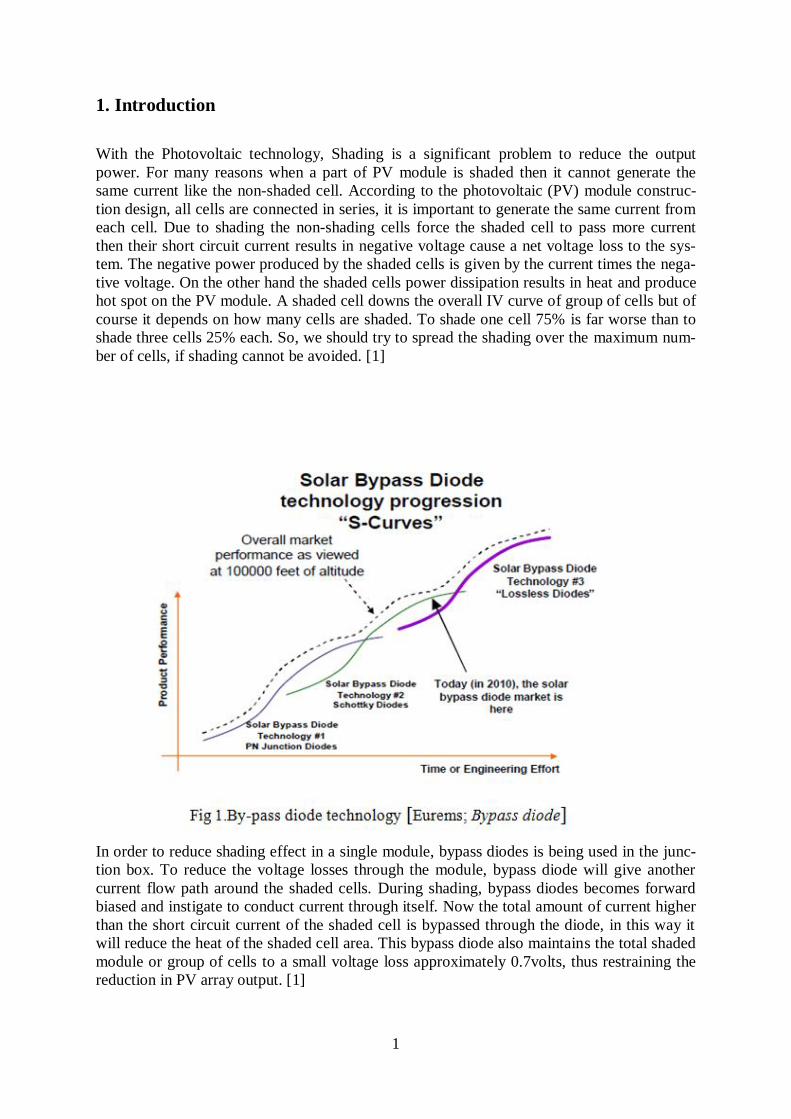
In order to reduce shading effect in a single module, bypass diodes is being used in the junc-
tion box. To reduce the voltage losses through the module, bypass diode will give another
current flow path around the shaded cells. During shading, bypass diodes becomes forward
biased and instigate to conduct current through itself. Now the total amount of current higher
than the short circuit current of the shaded cell is bypassed through the diode, in this way it
will reduce the heat of the shaded cell area. This bypass diode also maintains the total shaded
module or group of cells to a small voltage loss approximately 0.7volts, thus restraining the
reduction in PV array output. [1]

2
PN junction diode was used to give a bypass path but its forward voltage drop was relatively
high. That is why as a second technology that is converted to the schottky diode due to low
forward voltage. Traditionally they are axial diodes that snap into a connector in a junction
box on the back of the panel. The schottky diode forward voltage drop is almost 0.5 V which
is still an important cause of power reduction. In order to solve this problem, technology is
again changing to reach a point where forward voltage drop for the bypass diode will be very
low to increase the overall efficiency. [2]
In this project we are trying to use a new lossless diode technology that is produced by the
Microsemi Company. According to their specification its forward voltage drop is almost
0.4mV and has a negligible temperature rise at 10 ampere. Due to low temperature rising
system it can work with more reliability and can give a high longevity. With this new tech-
nology, photovoltaic efficiency will reach a new door. In order to look through the difference
between normal schottky diode and the lossless diode here we use a solar hybrid collector
from a Swedish Solar company (Solarus AB).

3
2. Objective and outline
The main objective of this thesis project is to compare the performance of PVT module with
the schottky diode and lossless in terms of output power and the efficiency. Also, this project
will present the amount of power that is saved by using the new lossless diode. To write this
paper all data is collected by using a solar hybrid collector, IV curve logger, Melacs control
device. In order to get a comparisons result between schottky diode and the lossless diode, all
data is collected from the outfield at the place of Älvkarleö (small city inside Sweden) during
the summer time.
Thesis project is organized as follows:
3: Background of this thesis project and mentioning of the new technology that is changing
with time.
4: Methods those are used to reach the goal of our research oriented thesis.
5: Making an experiment and presenting the experimental result that can give an exact solu-
tion for this work.
6: Discussion and concluding the best results.
4
3. Background
3.1 Solar Energy
Because of a many human activities, the deliberation of greenhouse gases is increasing day
by day. For using the fossil fuels, depletion of ozone and vanishing of large areas of forest is
going to be a big reason to increase the earth temperature; this condition will make an uncer-
tain future for the coming generation. To solve this problem solar energy is becoming a good
solution as a clean energy, bottomless resource that is easy to install, has an unlimited life as
well as may be used to both rural and city environment without difficulty.
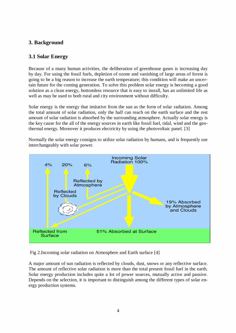
Solar energy is the energy that imitative from the sun as the form of solar radiation. Among
the total amount of solar radiation, only the half can reach on the earth surface and the rest
amount of solar radiation is absorbed by the surrounding atmosphere. Actually solar energy is
the key cause for the all of the energy sources in earth like fossil fuel, tidal, wind and the geo-
thermal energy. Moreover it produces electricity by using the photovoltaic panel. [3]
Normally the solar energy consigns to utilize solar radiation by humans, and is frequently use
interchangeably with solar power.
Fig 2.Incoming solar radiation on Atmosphere and Earth surface [4]
A major amount of sun radiation is reflected by clouds, dust, snows or any reflective surface.
The amount of reflective solar radiation is more than the total present fossil fuel in the earth.
Solar energy production includes quite a lot of power sources, mutually active and passive.
Depends on the selection, it is important to distinguish among the different types of solar en-
ergy production systems.

5
Two different ways are being used to make solar power, one is the direct transmission from
solar energy to current by using the PV panel and the other is solar concentration system to
produce steam in order to drive turbine.
Now-a-days solar energy technologies are well developed and improved. Different types of
solar technology are being used for the different function. By understanding the difference
along with the existing solar energy systems, it can be use more efficiently, cost effectively
and environmentally. By evaluating the efficiency, functionality and the economical feature
of the accessible systems and product we can get an efficient utilization.
3.2 Photovoltaic (PV) System
Photovoltaic system is the most direct way to make the electricity from solar radiation by
using photoelectric effect. This PV technology produces direct current from the semiconduc-
tor material when they are light up by Photon and the generated current is the direct propor-
tional with the photons that stick on the semiconductor material.
The atoms construct a lattice inside a crystal of pure silicon. Silicon’s atoms have nuclease
that contain photon (Positive charge) and electron (Negatively charge) in the shells. The
amount of electron in the valance band (outer cell) is not complete that’s why adjacent atoms
share electrons and grip each other together in the crystal.
The pure silicon atoms may be doped with a small amount of impurity and this doping mate-
rial can be containing more electrons in the valance bond compare than the pure silicon. Then
the negatively charged electron can move easily around then it is called n-type silicon. This
doping material can carry out electricity better than the pure silicon. On the other hand if the
pure silicon is doped with a material that has few electrons in the valance bond then there will
be a shortage of electron then it’s called P-type silicon. The tiny areas where electrons are
well missing are called holes that can as well move around.
Fig 4.Silicon wafer of solar cell [5]

6
In photovoltaic cell n-type and p-type silicon will be connected together. Due to attraction of
holes, electron will start moving across from n-type to p-type silicon. The junction area will
work as a barrier and discontinuing more electrons moving across n-type to p-type that create
an electric field across the junction. When the sun light is absorbed by this photovoltaic cell
then this energy will drive electrons across the junction. [5]
Fig 5.Solar cell working principle [5]
The efficiency may be 15-20% for this type of cell because silicon wafers cannot absorb all
light energy. Now-a-days a new type of complicated cell is being used to make the PV panel
that have multi junction and that can be able to absorb different light energy. [5]
Basically most of the photovoltaic devices are integrated by the PN junction in the semicon-
ductor. All photovoltaic cell are constructed by two wafers of doped silicon material one is n-
type and another is p-type that can make a junction. These two wafers are connected with
electrical connector. Usually photovoltaic cell is incredibly thin that is roughly 100mm di-
agonally. Individually each cell can produce around 0.7 volts and the maximum power being
generated at a voltage of roughly 0.4 volts. To make a module, some of this cell will be con-
nected in series and make a panel in order to protect from weather. In order to produce 24
volt panel 72 cell may be wired series within it and will give the peak power 28.8 volts. Now
these series connected cell are placed on the backing plate and the electrical connection wire
are lies above the plate and below the cells. In order to increase the light absorption, a non-
reflective layer will be on the top side of the cell. Lastly, a tough glass will be set on top and
whole structure will be assembled by an aluminium Frame. [6]
Fig 6. Design of a solar cell [6]
7
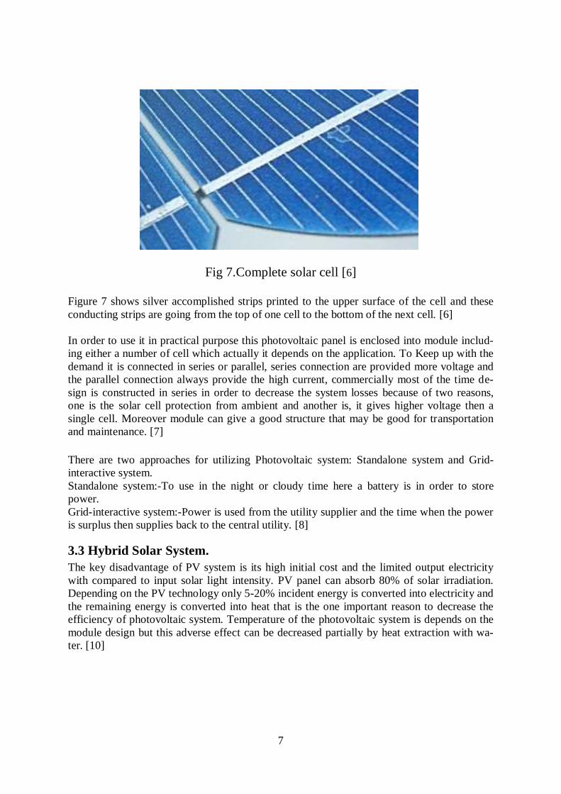
Fig 7.Complete solar cell [6]
Figure 7 shows silver accomplished strips printed to the upper surface of the cell and these
conducting strips are going from the top of one cell to the bottom of the next cell. [6]
In order to use it in practical purpose this photovoltaic panel is enclosed into module includ-
ing either a number of cell which actually it depends on the application. To Keep up with the
demand it is connected in series or parallel, series connection are provided more voltage and
the parallel connection always provide the high current, commercially most of the time de-
sign is constructed in series in order to decrease the system losses because of two reasons,
one is the solar cell protection from ambient and another is, it gives higher voltage then a
single cell. Moreover module can give a good structure that may be good for transportation
and maintenance. [7]
There are two approaches for utilizing Photovoltaic system: Standalone system and Grid-
interactive system.
Standalone system:-To use in the night or cloudy time here a battery is in order to store
power.
Grid-interactive system:-Power is used from the utility supplier and the time when the power
is surplus then supplies back to the central utility. [8]
3.3 Hybrid Solar System.
The key disadvantage of PV system is its high initial cost and the limited output electricity
with compared to input solar light intensity. PV panel can absorb 80% of solar irradiation.
Depending on the PV technology only 5-20% incident energy is converted into electricity and
the remaining energy is converted into heat that is the one important reason to decrease the
efficiency of photovoltaic system. Temperature of the photovoltaic system is depends on the
module design but this adverse effect can be decreased partially by heat extraction with wa-
ter. [10]
8
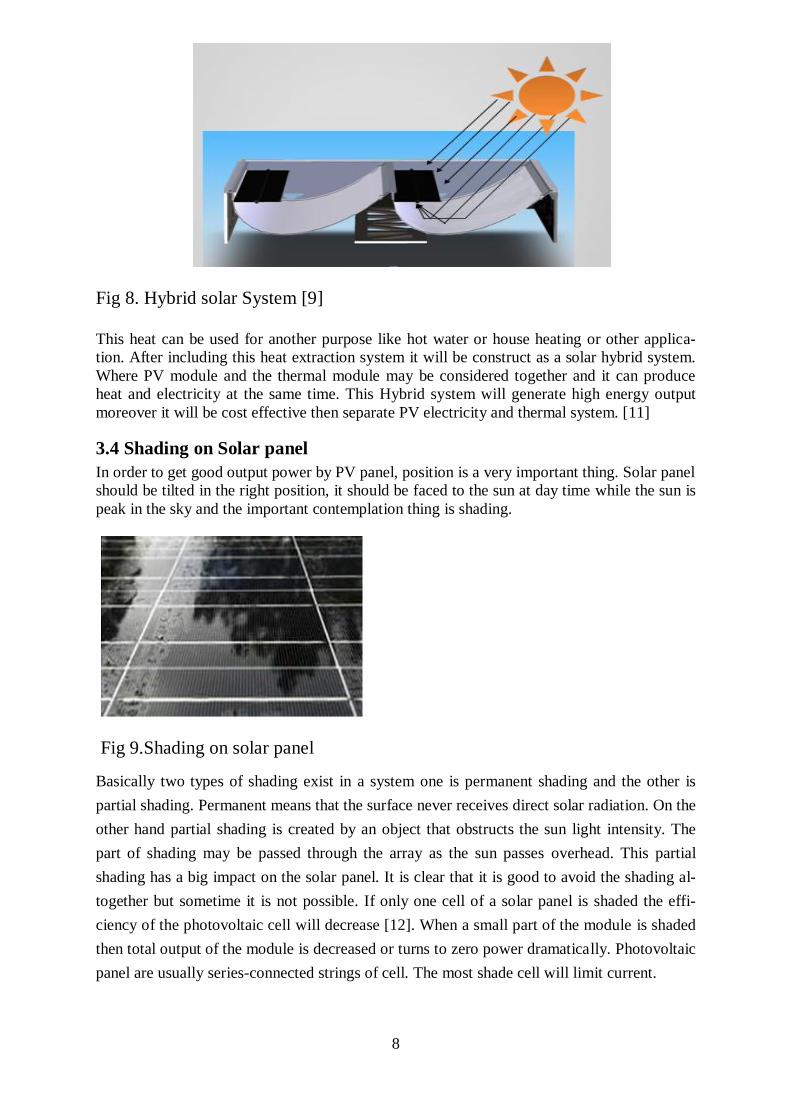
Fig 8. Hybrid solar System [9]
This heat can be used for another purpose like hot water or house heating or other applica-
tion. After including this heat extraction system it will be construct as a solar hybrid system.
Where PV module and the thermal module may be considered together and it can produce
heat and electricity at the same time. This Hybrid system will generate high energy output
moreover it will be cost effective then separate PV electricity and thermal system. [11]
3.4 Shading on Solar panel
In order to get good output power by PV panel, position is a very important thing. Solar panel
should be tilted in the right position, it should be faced to the sun at day time while the sun is
peak in the sky and the important contemplation thing is shading.
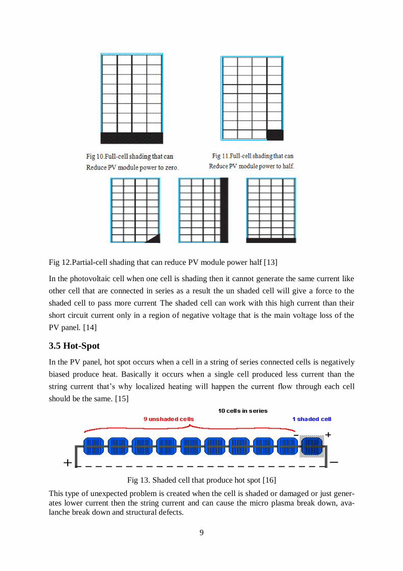
Fig 9.Shading on solar panel
Basically two types of shading exist in a system one is permanent shading and the other is
partial shading. Permanent means that the surface never receives direct solar radiation. On the
other hand partial shading is created by an object that obstructs the sun light intensity. The
part of shading may be passed through the array as the sun passes overhead. This partial
shading has a big impact on the solar panel. It is clear that it is good to avoid the shading al-
together but sometime it is not possible. If only one cell of a solar panel is shaded the effi-
ciency of the photovoltaic cell will decrease [12]. When a small part of the module is shaded
then total output of the module is decreased or turns to zero power dramatically. Photovoltaic
panel are usually series-connected strings of cell. The most shade cell will limit current.
9
Fig 12.Partial-cell shading that can reduce PV module power half [13]
In the photovoltaic cell when one cell is shading then it cannot generate the same current like
other cell that are connected in series as a result the un shaded cell will give a force to the
shaded cell to pass more current The shaded cell can work with this high current than their
short circuit current only in a region of negative voltage that is the main voltage loss of the
PV panel. [14]
3.5 Hot-Spot
In the PV panel, hot spot occurs when a cell in a string of series connected cells is negatively
biased produce heat. Basically it occurs when a single cell produced less current than the
string current that’s why localized heating will happen the current flow through each cell
should be the same. [15]
Fig 13. Shaded cell that produce hot spot [16]
This type of unexpected problem is created when the cell is shaded or damaged or just gener-
ates lower current then the string current and can cause the micro plasma break down, ava-
lanche break down and structural defects.
10
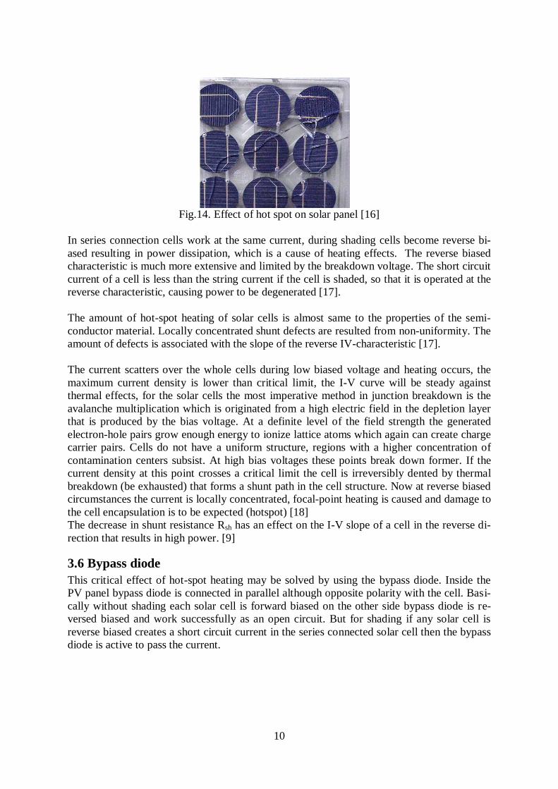
Fig.14. Effect of hot spot on solar panel [16]
In series connection cells work at the same current, during shading cells become reverse bi-
ased resulting in power dissipation, which is a cause of heating effects. The reverse biased
characteristic is much more extensive and limited by the breakdown voltage. The short circuit
current of a cell is less than the string current if the cell is shaded, so that it is operated at the
reverse characteristic, causing power to be degenerated [17].
The amount of hot-spot heating of solar cells is almost same to the properties of the semi-
conductor material. Locally concentrated shunt defects are resulted from non-uniformity. The
amount of defects is associated with the slope of the reverse IV-characteristic [17].
The current scatters over the whole cells during low biased voltage and heating occurs, the
maximum current density is lower than critical limit, the I-V curve will be steady against
thermal effects, for the solar cells the most imperative method in junction breakdown is the
avalanche multiplication which is originated from a high electric field in the depletion layer
that is produced by the bias voltage. At a definite level of the field strength the generated
electron-hole pairs grow enough energy to ionize lattice atoms which again can create charge
carrier pairs. Cells do not have a uniform structure, regions with a higher concentration of
contamination centers subsist. At high bias voltages these points break down former. If the
current density at this point crosses a critical limit the cell is irreversibly dented by thermal
breakdown (be exhausted) that forms a shunt path in the cell structure. Now at reverse biased
circumstances the current is locally concentrated, focal-point heating is caused and damage to
the cell encapsulation is to be expected (hotspot) [18]
The decrease in shunt resistance Rsh has an effect on the I-V slope of a cell in the reverse di-
rection that results in high power. [9]
3.6 Bypass diode
This critical effect of hot-spot heating may be solved by using the bypass diode. Inside the
PV panel bypass diode is connected in parallel although opposite polarity with the cell. Basi-
cally without shading each solar cell is forward biased on the other side bypass diode is re-
versed biased and work successfully as an open circuit. But for shading if any solar cell is
reverse biased creates a short circuit current in the series connected solar cell then the bypass
diode is active to pass the current.
11
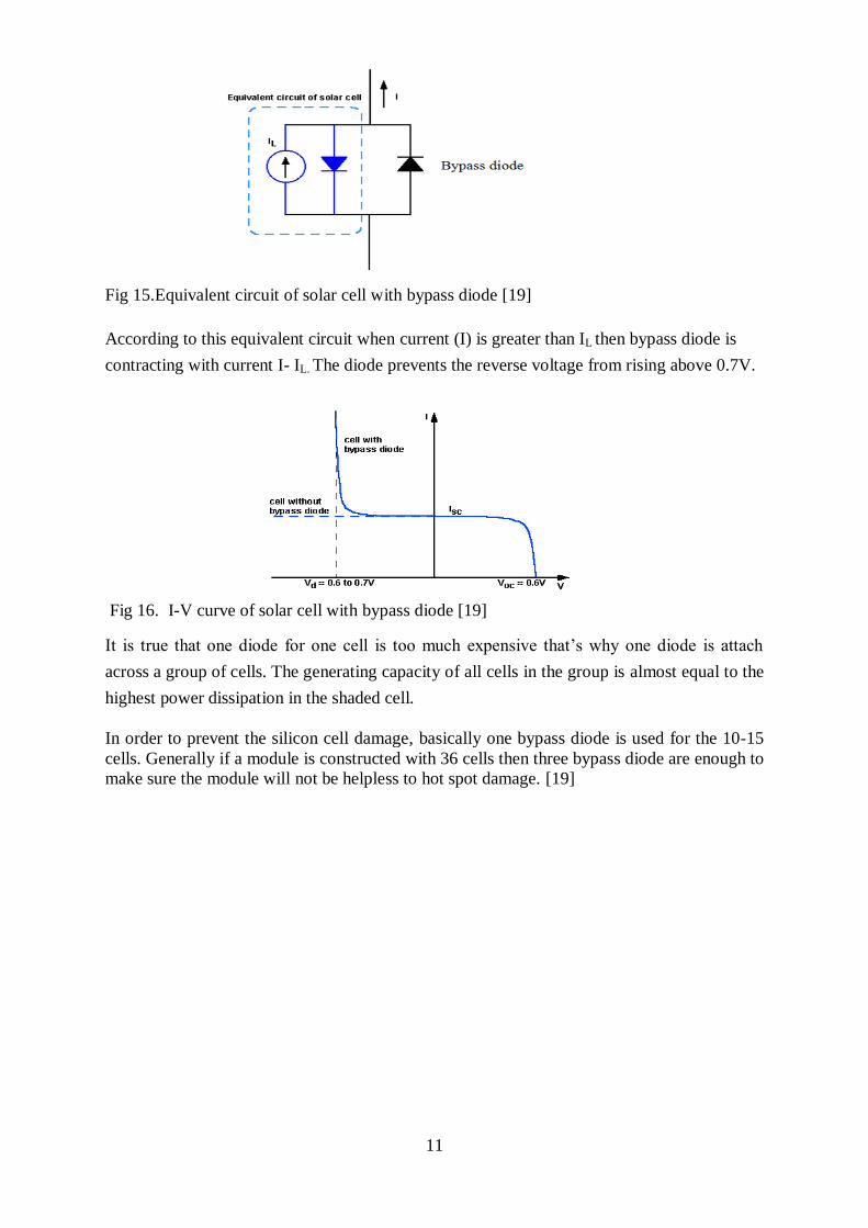
Fig 15.Equivalent circuit of solar cell with bypass diode [19]
According to this equivalent circuit when current (I) is greater than IL then bypass diode is
contracting with current I- IL. The diode prevents the reverse voltage from rising above 0.7V.
Fig 16. I-V curve of solar cell with bypass diode [19]
It is true that one diode for one cell is too much expensive that’s why one diode is attach
across a group of cells. The generating capacity of all cells in the group is almost equal to the
highest power dissipation in the shaded cell.
In order to prevent the silicon cell damage, basically one bypass diode is used for the 10-15
cells. Generally if a module is constructed with 36 cells then three bypass diode are enough to
make sure the module will not be helpless to hot spot damage. [19]
12
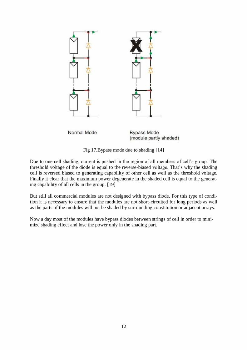
Fig 17.Bypass mode due to shading [14]
Due to one cell shading, current is pushed in the region of all members of cell’s group. The
threshold voltage of the diode is equal to the reverse-biased voltage. That’s why the shading
cell is reversed biased to generating capability of other cell as well as the threshold voltage.
Finally it clear that the maximum power degenerate in the shaded cell is equal to the generat-
ing capability of all cells in the group. [19]
But still all commercial modules are not designed with bypass diode. For this type of condi-
tion it is necessary to ensure that the modules are not short-circuited for long periods as well
as the parts of the modules will not be shaded by surrounding constitution or adjacent arrays.
Now a day most of the modules have bypass diodes between strings of cell in order to mini-
mize shading effect and lose the power only in the shading part.
13
3.7 Schottky Diode
Schottky diode is a special type of semiconductor diode that works with low forward voltage
drop. It has some internal resistance to that current flow, that’s the reason why a small volt-
age drop across the diode terminals when current flows through a diode.
Fig 18.Schottky diode schematic symbol
Schottky diode forward voltage drop is around 0.15 volts to 0.45 volts on the other hand it is
0.6-1.7 volts for the normal silicon diode. Due to this low forward voltage drop schottky di-
ode can provide fast switching action and it can increase the system efficiency.
Schottky diode is constructed by metal-semiconductor junction that creates a schottky barrier.
Basically N-type silicon is used as semiconductor that acts as the cathode and the metal part
work as an anode of the diode. This schottky barrier can give low forward voltage drop and
very fast switching action.
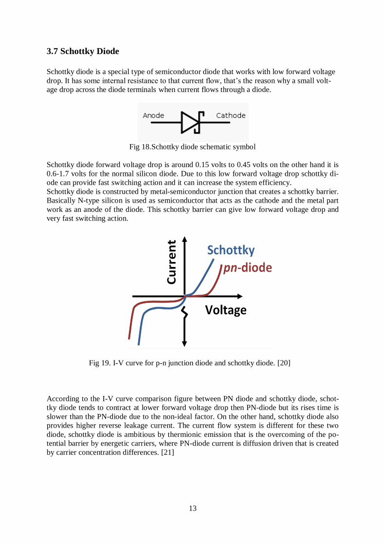
Fig 19. I-V curve for p-n junction diode and schottky diode. [20]
According to the I-V curve comparison figure between PN diode and schottky diode, schot-
tky diode tends to contract at lower forward voltage drop then PN-diode but its rises time is
slower than the PN-diode due to the non-ideal factor. On the other hand, schottky diode also
provides higher reverse leakage current. The current flow system is different for these two
diode, schottky diode is ambitious by thermionic emission that is the overcoming of the po-
tential barrier by energetic carriers, where PN-diode current is diffusion driven that is created
by carrier concentration differences. [21]

14
3.8 New Lossless Diode
It is true that the efficiency is a still big question in the photovoltaic technology. To work out
this problem photovoltaic technology is altering. To improve this photovoltaic technology
lossless bypass diode has an important role as well as the photovoltaic material efficiency.
This lossless diode technology will open a new entrance to increase the photovoltaic effi-
ciency as well as the reliability.
To cope with the shading effect in the photovoltaic technology, in the beginning manufac-
turer used PN junction diode to give a bypass path. This PN junction diode has a forward
voltage drop 0.7 to 1.0 volt and the reverse breakdown voltage was almost 600 volts. This
diode could tolerate the heat for the low ampere. But to get more output wafer size increased
and the string current increased 5, 6 or more than 8 ampere. That’s why the manufacturer
company had changed their technology from PN junction diode to Schottky diode, its forward
voltage drop was around 0.5volt that is the half of the PN junction diode and it was good in
the heating condition. But unfortunately PN junction diode and the Schottky diode had re-
verse significant breakdown voltage that is almost 40 to 60 volts. This initiated another prob-
lem. On the other hand schottky diodes are absorbent at the high temperature and it can easily
be eternally damage by passing energy. Due to fail it may be open then it leave the parallel
cell and make a hot spot during the shading period. On the other hand (this term is used for
comparisons of two opposite things) due to fail it may be shorted that produce minimum en-
ergy.
By-pass diode is going to change the photovoltaic technology. At this moment some re-
searchers are going to develop a new type of diode. This new diode is called lossless diode
that forward voltage drop is 40 to50 mV that was 0.4 V for the schottky diode. In reverse bias
mode this lossless diode has high temperature leakages measured in micro-amperes where the
schottky diode was mili-amperes. [2]
3.9 Theoretical explanation of Photovoltaic Cell
The equivalent circuit of the solar cells may be modelled when a current source is parallel
with a diode. The solar cells perform like a diode when light is absent to generate any current.
With the increasing of incident light intensity, current is generated by the PV cell. I-V curve
of the solar cell given below-
Fig 20.I-V curve of Solar cell and electrical diagram [22]

15
According to the Kirchhoff’s current law in an ideal solar cell, the amount of current IL that is
generated by photoelectric effect minus the diode current ID is equal to the total current I.
I = I L- ID = IL-I0
Where,
Io=Saturation Current
q =Charge 1.6*10-19
Coulombs
K=1.38*10-23
J/K
T=Temperature (Kelvin)
V=Cell voltage
In order to explain detail about the equivalent circuit a new figure shown below where RS and
RSH are going to represent series and shunt resistance. [22]
Fig 21.Equivalent circuit of solar cell [22]
Due to this new model the associate equation will be like-
I=IL-I0
Where n is the diode ideal factor and the value of n should be between 1 and 2 unit. For the
above electrical circuit construction the overall I-V curve of the solar cell drawn in figure 22
below where VOC is the open circuit voltage and ISC is the short circuit current and the general
performance of solar cell can be determined from this I-V curve:-
Fig 22. I-V curve of solar cell

16
Short circuit current (ISC) When the voltage is zero with the low importance then the short circuit is represent in the
term of short circuit condition.
I (when V=0) =ISC
At the maximum current value in the power quadrant and the beginning of the forward-bias
sweep is the main cause of ISC occurs. [22]
ISC=IMAX=IL (Forward bias power quadrant)
Open circuit voltage (VOC) When there is no current passing through the solar cell then it creates the open circuit voltage.
V (When I=0) =VOC
VOC is also represented by the maximum voltage difference across the cell for a forward-bias
sweep in the power quadrant. [22]
VOC= V MAX (Forward bias power quadrant)
Generated solar cell power can be calculated by the equation P=VI where power will be zero
at ISC and VOC points. The maximum value of power will be arising between ISC and VOC
points. At the maximum power point the maximum current and maximum voltage is repre-
sented by IMP and VMP respectively.
Fig 23. Maximum power for PV cell [22]
In order to measure the fundamental quality of solar cell, fill factor is an important term that
is symbolized by its abbreviation FF. The fill factor is calculated by the ratio of the maximum
power from solar cell to the produce of ISC and VOC. [22]
FF =
=

17
Fig 24.Fill factor from the I-V curve [22]
Usually the fill factor vary from 0.5 to 0.82 even though a large fill factor value is desirable
as well as the I-V curve should be more square-like.
Efficiency (η)
The efficiency of the solar cell can be measured by ratio between electric output power
(Watt), Pout and solar radiation input (Watt) PIN. The Value of POUT is the same of PMAX value
because to get maximum efficiency the solar cell can be operated to its maximum power out-
put.
η =
=> ηmax =
The maximum efficiency of the solar panel not only depend on the irradiance of incident light
but also like all I-V parameter can also be pretentious by ambient condition like as tempera-
ture and the spectrum of the incident light. That’s why it is important to compare the similar
light and temperature situation. [22]
Shunt resistance (Rsh) and series resistance (Rs)
The dissipation of power across the Shunt resistance (Rsh) and Series resistance (Rs ) can be
an important reason to reduce the efficiency of solar cell. When solar cell is consider as the
term of ideal then RSH should be infinite and Rs should be zero, at the same time should not
provide the alternative path to current flow, ensuing in no future voltage drop before the load.
The relationship between these two parasitic resistances is like- increasing RS and decreasing
RSH will be the causes of decreasing fill factor as well as Pmax. [22]
18
Fig 25. Effect of diverging RS and RSH [22]
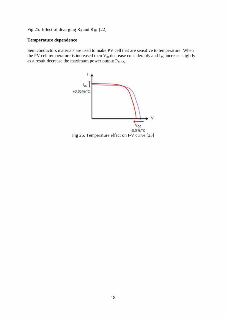
Temperature dependence
Semiconductors materials are used to make PV cell that are sensitive to temperature. When
the PV cell temperature is increased then Voc decrease considerably and ISC increase slightly
as a result decrease the maximum power output PMAX.
Fig 26. Temperature effect on I-V curve [23]

19
4. Methodologies
To congregate with a good result this paper was involved by different activities. Since this
thesis paper was related with the result of practical aspects that’s why we have done lot of
activities in the outdoor. During the time of practical work it was also important to go
through the research paper that is directly related without research oriented thesis paper.
Actually this thesis paper was built up by the following approach:-
a. Practical approach
Installing a schottky diode and a new loss less diode inside the module of hy-
brid solar collector
Each diode was connected in parallel with the group of solar cells
Melacs control system was used in order to measure solar radiation,
Water input and output temperature and amount of water flow.
IV loger was used to make an IV curve for the module.
b. Theoretical approach
Research paper review for the schottky diode and the loss less diode.
Hybrid solar collector research paper consideration.
Documentation paper review from Solarus in order to get a clear idea about
their hybrid solar system
Paper review from Micro semi Company.
After using these above approaches it was easy to make a comparison between schottky diode
and the lossless diode for the term of output power and efficiency.
20
5. Experimental set up and Experimental Result
To establish the comparison between schottky diode and the loss less diode, this experiment
was done with a hybrid solar collector that was made by solarus AB, Sweden and the lossless
diode from Microsemi Company.
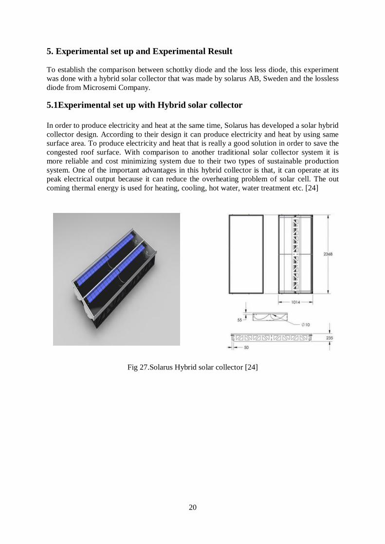
5.1Experimental set up with Hybrid solar collector
In order to produce electricity and heat at the same time, Solarus has developed a solar hybrid
collector design. According to their design it can produce electricity and heat by using same
surface area. To produce electricity and heat that is really a good solution in order to save the
congested roof surface. With comparison to another traditional solar collector system it is
more reliable and cost minimizing system due to their two types of sustainable production
system. One of the important advantages in this hybrid collector is that, it can operate at its
peak electrical output because it can reduce the overheating problem of solar cell. The out
coming thermal energy is used for heating, cooling, hot water, water treatment etc. [24]
Fig 27.Solarus Hybrid solar collector [24]

21
Technical specification
Structure
Manufacturer :Solarus AB
Brand name :SOLARUS CPC-T
Manufacturer :2368mm*1040mm*235mm
Absorber area :0.68 m2
Aperture area :2.17m2
Gross area :2.40 m2
Weight :30kg
Cells
Number of cells :152
Cell dimension :26.6mm*150mm*200mm
Max power rating(Pmax) :Up to 300W
Max operating temperature :200C
Max power voltage(Vp max) :18.4V
Max power current(Ipmax) :14.76V
Open circuit voltage(Voc) :22.8V
Short circuit current(Isc) :16.04A
Absorber
Material
:Copper tube integrated in aluminium
plate
Construction type :Two strips in series
Coating :Nickel selective surface
Peak power :1500 Watt per collector
Capacity :0.364 L/module
Maximum operating pressure :10 bar
Stagnation temperature :200C
Casing
Material :Anodized aluminium frame
Gross dimension(L*W*H) :1014mm*2368mm*235mm
Sealing material :Silicon
Connection :Copper tube,10mm,2connections

22
Fig 28. Double absorber and aluminium reflector [25]
The PV panel output depends upon the angular dependent of the angle of incidence. The sun
moves from east to west plane then the angular dependence similar to a flat collector. On the
other hand if the sun move in the north-south plane then the angular dependence is quite dif-
ferent that shown in the figure 29. When the angle is greater than the reflector optical axis the
efficiency goes down rapidly.
Fig 29.Efficiency at different irradiation angles [25]
The absorber of the Solarus hybrid collector is manufactured in the width of 150mm. The
absorber contain the cells on both side and the reflector is used to focus light on to the bottom
side solar cell in order to get maximum output by using the same area. This hybrid solar col-
lector system can delivered around 15% electrical energy and the rest of the energy is re-
leased as a heat. To use this heat, a tube is used inside the absorber to flow the water that can
consume the heat energy in order to get hot water.
23
12A
100V
100mj
VF at IF=12A 0.58V
Non-repetitive avalanche energy EAS at IAS = 2.0 A, TJ = 25
°C
Primary Specification
Maximum average forward rectified current IF(AV)
Maximum repetitive peak reverse voltage VRRM
Peak forward surge current 10 ms single half sine-wave
superimposed on rated load IFSM
200A
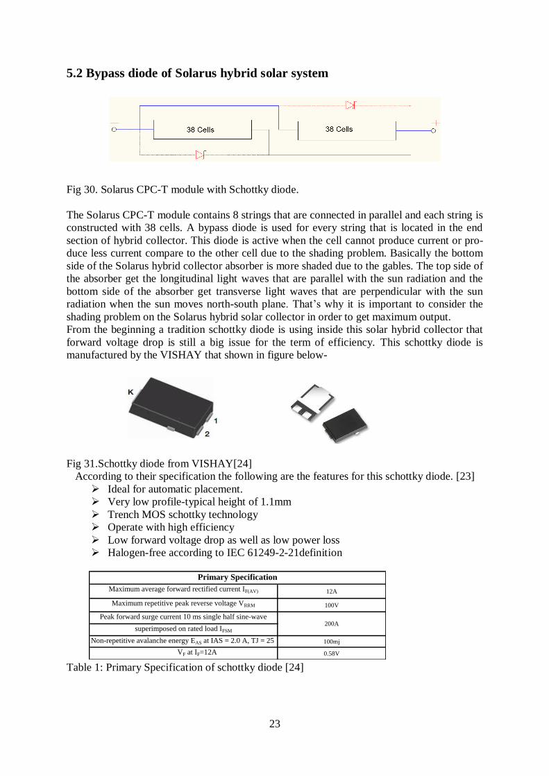
5.2 Bypass diode of Solarus hybrid solar system
Fig 30. Solarus CPC-T module with Schottky diode.
The Solarus CPC-T module contains 8 strings that are connected in parallel and each string is
constructed with 38 cells. A bypass diode is used for every string that is located in the end
section of hybrid collector. This diode is active when the cell cannot produce current or pro-
duce less current compare to the other cell due to the shading problem. Basically the bottom
side of the Solarus hybrid collector absorber is more shaded due to the gables. The top side of
the absorber get the longitudinal light waves that are parallel with the sun radiation and the
bottom side of the absorber get transverse light waves that are perpendicular with the sun
radiation when the sun moves north-south plane. That’s why it is important to consider the
shading problem on the Solarus hybrid solar collector in order to get maximum output.
From the beginning a tradition schottky diode is using inside this solar hybrid collector that
forward voltage drop is still a big issue for the term of efficiency. This schottky diode is
manufactured by the VISHAY that shown in figure below-
Fig 31.Schottky diode from VISHAY[24]
According to their specification the following are the features for this schottky diode. [23]
Ideal for automatic placement.
Very low profile-typical height of 1.1mm
Trench MOS schottky technology
Operate with high efficiency
Low forward voltage drop as well as low power loss
Halogen-free according to IEC 61249-2-21definition
Table 1: Primary Specification of schottky diode [24]

24
Table 2. Electrical Characteristics of schottky diode [23]
Fig 32. Maximum forward current duration curve [23]
Fig 33. Forward power loss curve [23]
Breakdown voltage,VBR IR=1.0mA
IF = 5 A
IF=12A
IF = 5 A
IF=12A
TA=125̊ C
Test Conditions
TA=25̊ C
Instantaneous forward
voltage,VF
TA=25̊ C
TA=125̊ C
Reverse current,IR
VR = 70VTA=25̊ C
TA=125̊ C
VR = 100VTA=25̊ C
Electrical characteristics
Parameter

25
Fig 34. Typical Instantaneous forward curves [23]
5.3 Solar lossless bypass diode from Microsemi
Microsemi has developed a new lossless solar bypass diode (LX2400) that forward voltage
drop is relatively very low. This diode forward voltage drop is 50mV at 10A that generate
10ºC temperature rise for the coolest operation and it can fully operate from -65ºC to +165ºC.
Moreover in the reverse mode Micro semi diode can block 22V at less than 100 º C leakages
current without breakdown. Due to the low forward voltage drop, it produces less heat and
can operate with lower temperature that makes the system more reliable and longer life. The
reliability and the longer life of this diode can reduce the operational expenses and the war-
ranty cost. For the period of lightning strike, lightning survivability give a bidirectional low
impedance path that provide the lowest power dissipation in the LX2400. [24]
Fig 35.Loss less Micro semi Solar bypasses diode [24]
Area of Speciality
Extremely low operating forward voltage drop, VF=50mV at 10A that enhance the
system efficiency and reduce the power dissipation, reverse mode: 100µA at 90ºC.
Low heat generation, less than 10ºC rise at 10A.
Life time is around 30years.
Low operating expense and warranty cost.
Bidirectional lightning survivability.
No heat sink required.
26
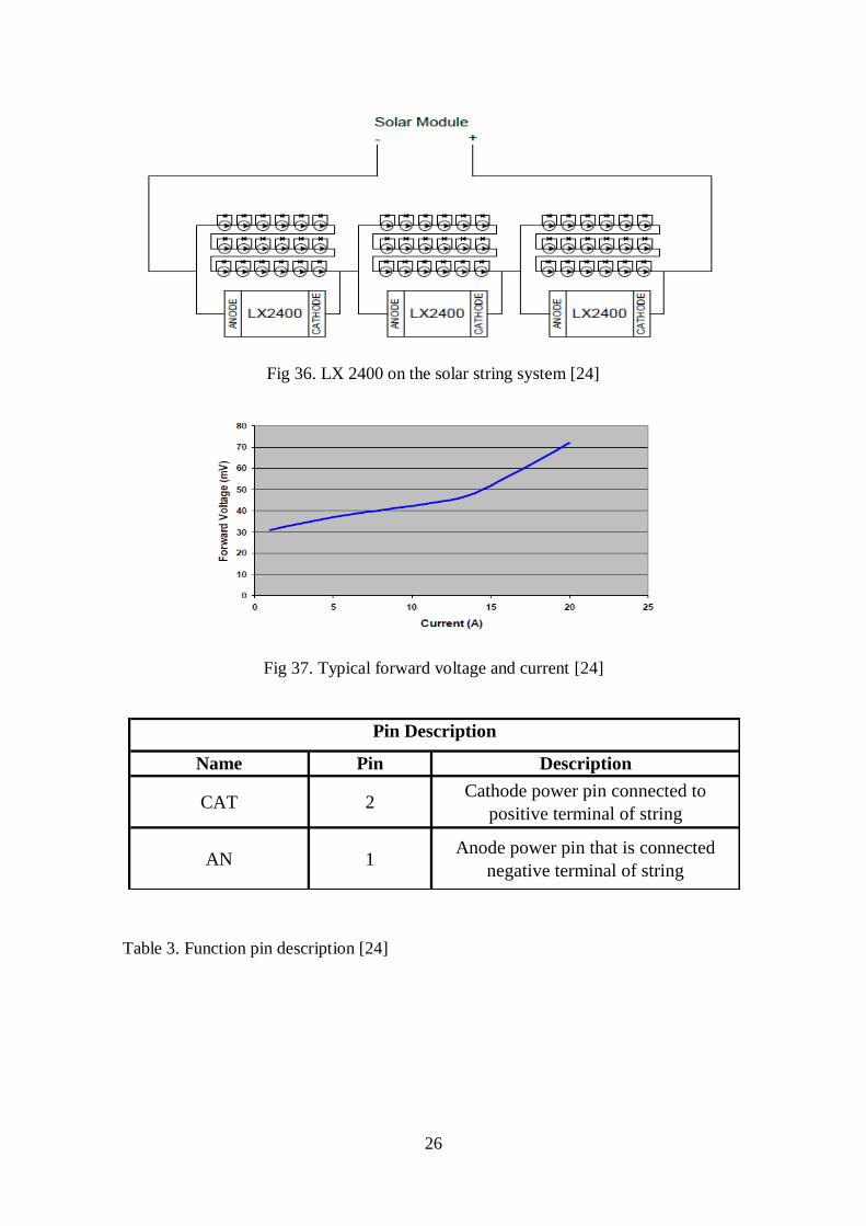
Fig 36. LX 2400 on the solar string system [24]
Fig 37. Typical forward voltage and current [24]
Table 3. Function pin description [24]
Name Pin Description
CAT 2Cathode power pin connected to
positive terminal of string
AN 1Anode power pin that is connected
negative terminal of string
Pin Description
27
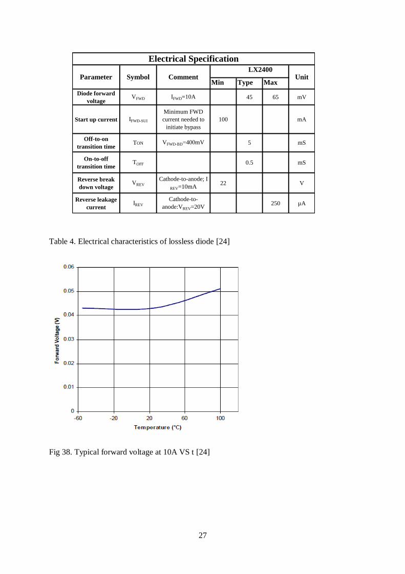
Min Type Max
Diode forward
voltageVFWD IFWD=10A 45 65 mV
Start up current IFWD-SUI
Minimum FWD
current needed to
initiate bypass
100 mA
On-to-off
transition timeTOFF 0.5 mS
Reverse break
down voltageVREV
Cathode-to-anode; I
REV=10mA22 V
Reverse leakage
currentIREV
Cathode-to-
anode:VREV=20V250 µA
Off-to-on
transition timeVFWD-BD=400mV 5 mSTON
Electrical Specification
Parameter Symbol Comment LX2400
Unit
Table 4. Electrical characteristics of lossless diode [24]
Fig 38. Typical forward voltage at 10A VS t [24]
28
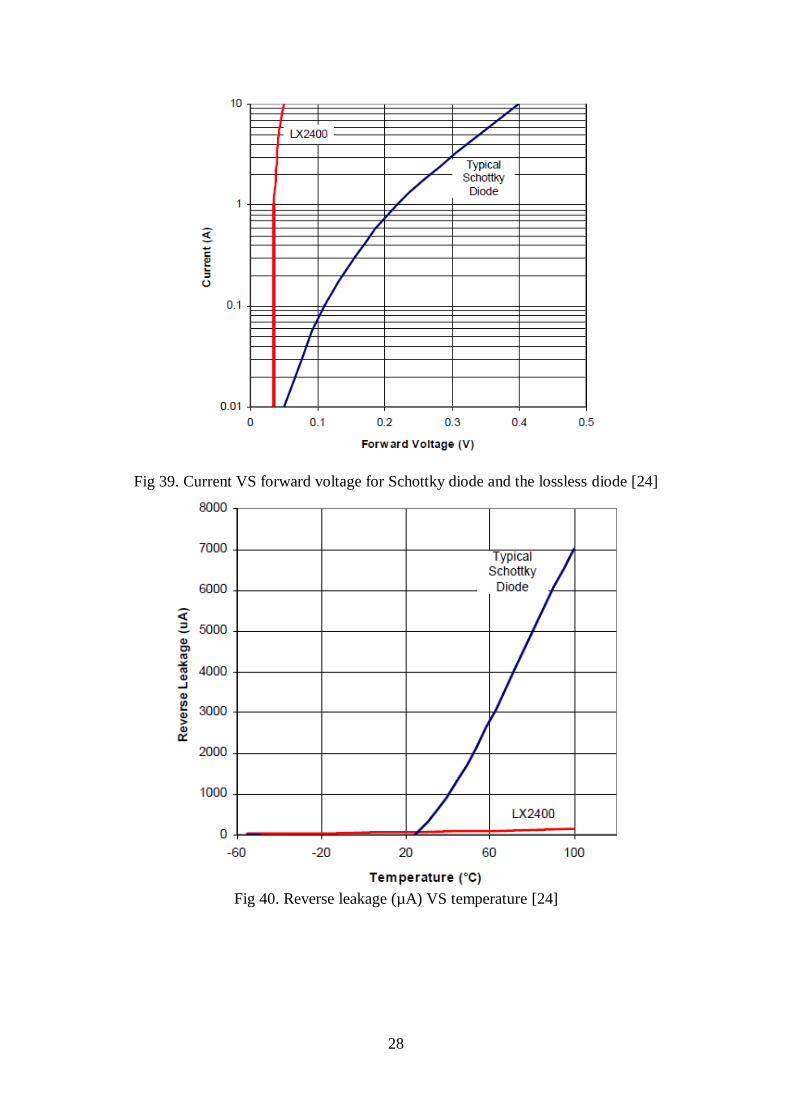
Fig 39. Current VS forward voltage for Schottky diode and the lossless diode [24]
Fig 40. Reverse leakage (µA) VS temperature [24]
29
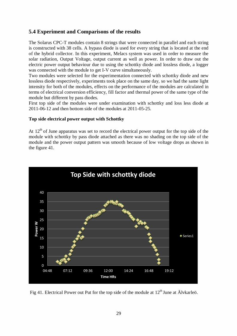
5.4 Experiment and Comparisons of the results The Solarus CPC-T modules contain 8 strings that were connected in parallel and each string
is constructed with 38 cells. A bypass diode is used for every string that is located at the end
of the hybrid collector. In this experiment, Melacs system was used in order to measure the
solar radiation, Output Voltage, output current as well as power. In order to draw out the
electric power output behaviour due to using the schottky diode and lossless diode, a logger
was connected with the module to get I-V curve simultaneously.
Two modules were selected for the experimentation connected with schottky diode and new
lossless diode respectively, experiments took place on the same day, so we had the same light
intensity for both of the modules, effects on the performance of the modules are calculated in
terms of electrical conversion efficiency, fill factor and thermal power of the same type of the
module but different by pass diodes.
First top side of the modules were under examination with schottky and loss less diode at
2011-06-12 and then bottom side of the modules at 2011-05-25.
Top side electrical power output with Schottky
At 12th
of June apparatus was set to record the electrical power output for the top side of the
module with schottky by pass diode attached as there was no shading on the top side of the
module and the power output pattern was smooth because of low voltage drops as shown in
the figure 41.
Fig 41. Electrical Power out Put for the top side of the module at 12th
June at Älvkarleö.
0
5
10
15
20
25
30
35
40
04:48 07:12 09:36 12:00 14:24 16:48 19:12
Po
wer
W
Time HRs
Top Side with schottky diode
Series1

30
Getting on with the precise calculation many data have been taken. In order to organize this
large number of data only the optimum values are considered. For the top side of one module
34.8 W (see appendix) was measured as a maximum power.The power at Y-axis and the time at X-axis shown in the figure 41 and IV curve are shown in figure 42.
Fig 42. Measured I-Vcurves for the cells on the top side of the module during the period
09:00 to 14:00 Hrs , 2011-06-12.
Top side electrical power output with lossless diode
At 12th
of June again the top side of the same module brought under observation with the
same procedure with new lossless diode.
The pattren for the electrical power out put was the same as there were no shadow on the top
side of the module
Fig 43. Electrical power out for the top side of the module, at 12st June 2011, Älvkarleö.
On the day of 12st june,the maximum output power of top side of the module was 37.3 W
(see appendix) as shown in the figure 43 and IV curves are shown in the figure 44.
0
5
10
15
20
25
30
35
40
4:48 7:12 9:36 12:00 14:24 16:48 19:12
Power out put with lossless diode
Power
31
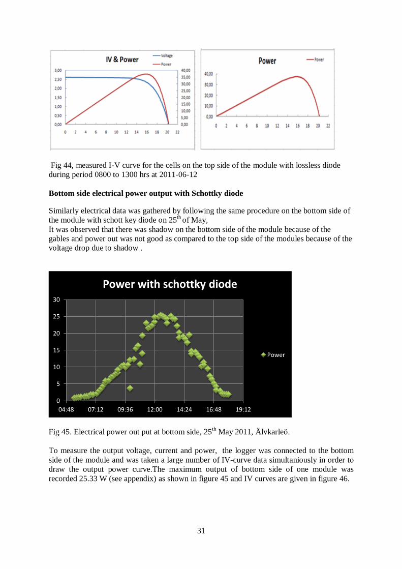
Fig 44, measured I-V curve for the cells on the top side of the module with lossless diode
during period 0800 to 1300 hrs at 2011-06-12
Bottom side electrical power output with Schottky diode
Similarly electrical data was gathered by following the same procedure on the bottom side of
the module with schott key diode on 25th
of May,
It was observed that there was shadow on the bottom side of the module because of the
gables and power out was not good as compared to the top side of the modules because of the
voltage drop due to shadow .
Fig 45. Electrical power out put at bottom side, 25th May 2011, Älvkarleö.
To measure the output voltage, current and power, the logger was connected to the bottom
side of the module and was taken a large number of IV-curve data simultaniously in order to
draw the output power curve.The maximum output of bottom side of one module was
recorded 25.33 W (see appendix) as shown in figure 45 and IV curves are given in figure 46.
0
5
10
15
20
25
30
04:48 07:12 09:36 12:00 14:24 16:48 19:12
Power with schottky diode
Power
32
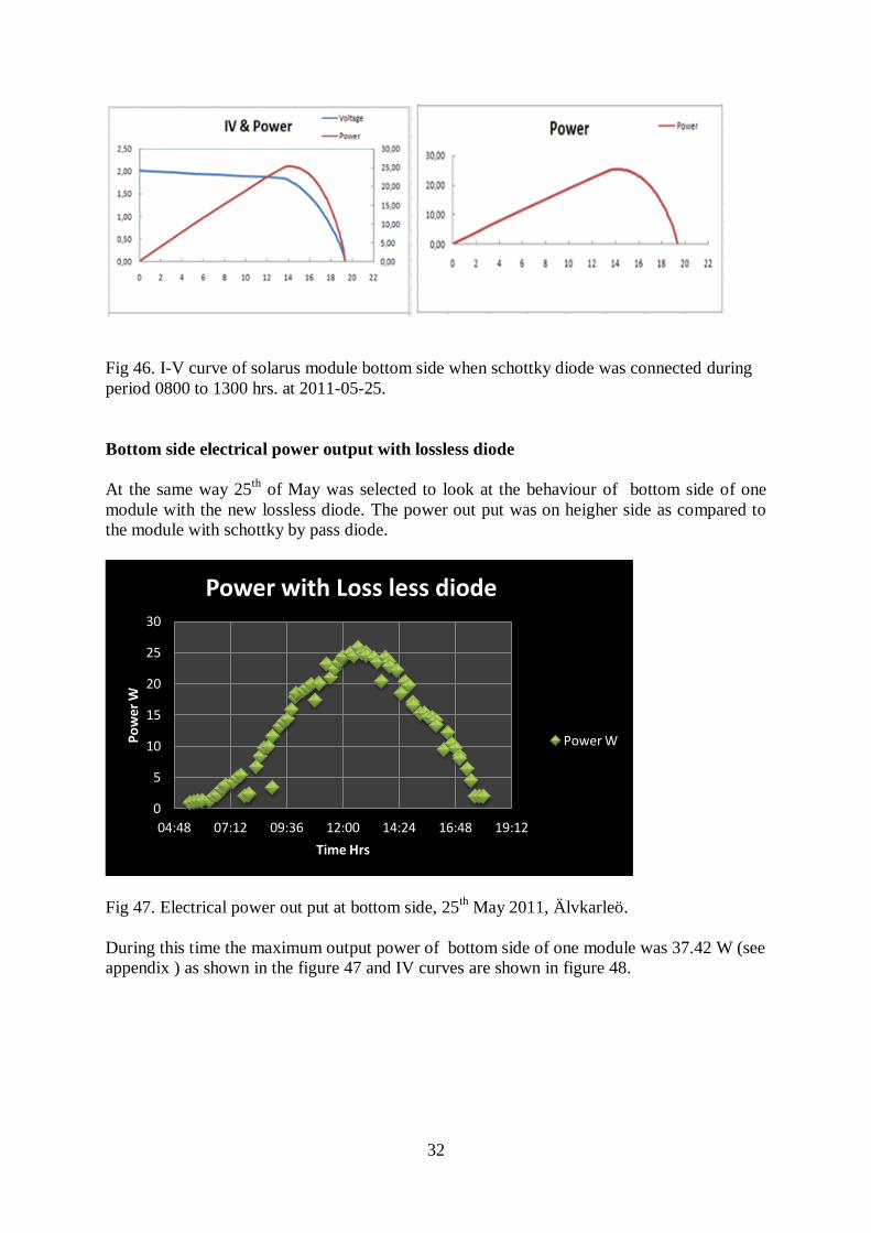
Fig 46. I-V curve of solarus module bottom side when schottky diode was connected during
period 0800 to 1300 hrs. at 2011-05-25.
Bottom side electrical power output with lossless diode
At the same way 25th
of May was selected to look at the behaviour of bottom side of one
module with the new lossless diode. The power out put was on heigher side as compared to
the module with schottky by pass diode.
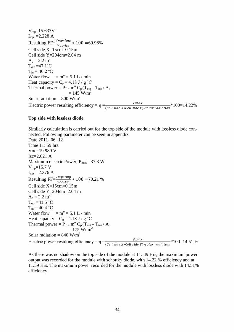
Fig 47. Electrical power out put at bottom side, 25th May 2011, Älvkarleö.
During this time the maximum output power of bottom side of one module was 37.42 W (see
appendix ) as shown in the figure 47 and IV curves are shown in figure 48.
0
5
10
15
20
25
30
04:48 07:12 09:36 12:00 14:24 16:48 19:12
Po
wer
W
Time Hrs
Power with Loss less diode
Power W

33
Fig 48. I-V curve of Solarus module bottom side when lossless diode was connected during
0800 to 1300 Hrs. on 2011-05-25.
5.5 Calculation
After gathering all the data for the top and bottom side of the module with schottky and
lossless diode, e.g electrical power out put, voltage, current, flow rate, sun light radiations,
temprature. Following three parameters are calculated and the results are compared for the
module with schott key diode and the module with loss diode.
Thermal output (PT), fill factor (FF) and electrical conversion efficiency (η) was calculated
by using equation 5.1, 5.2 and 5.3 respectively for the same solar CPC-T module with schot-
tky diode and lossless diode.
PT = mo Cp (Tout – Tin) / Ac 5.1
FF =
5.2
η =
*100 5.3
Where mo
is the mass flow rate and Cp is the heat capacity and Tout and Tin is the inlet and out
let temperature of the fluid and Vmp is the voltage at maximum power and same is the Imp and
Voc and Isc open circuit voltage and short circuit current, Pmax is the maximum power output
recorded at a particular day and X and Y are the dimensions of the cell side.
Top side with schottky diode
After getting experimental data following calculations made for the module with schottky
diode for top side of the module. Following measurements can be seen in appendix.
Date 2011- 06 -12
Time 11: 49 hrs.
Voc=19.989V
Isc=2.490A
Maximum electric Power, Pmax= 34.83 W
34
Vmp=15.633V
Imp =2.228 A
Resulting FF=
69.98%
Cell side X=15cm=0.15m
Cell side Y=204cm=2.04 m
Ac = 2.2 m2
Tout =47.1˚C
Tin = 46.2 ºC
Water flow = mo = 5.1 L / min
Heat capacity = Cp = 4.18 J / g ˚C
Thermal power = PT = mo Cp (Tout – Tin) / Ac
= 145 W/m2
Solar radiation = 800 W/m2
Electric power resulting efficiency = η =
*100=14.22%
Top side with lossless diode
Similarly calculation is carried out for the top side of the module with lossless diode con-
nected. Following parameter can be seen in appendix
Date 2011- 06 -12
Time 11: 59 hrs.
Voc=19.989 V
Isc=2.621 A
Maximum electric Power, Pmax= 37.3 W
Vmp=15.7 V
Imp =2.376 A
Resulting FF=
70.21 %
Cell side X=15cm=0.15m
Cell side Y=204cm=2.04 m
Ac = 2.2 m2
Tout =41.5 ˚C
Tin = 40.4 ˚C
Water flow = mo = 5.1 L / min
Heat capacity = Cp = 4.18 J / g ˚C
Thermal power = PT = mo Cp (Tout – Tin) / Ac
= 175 W/ m2
Solar radiation = 840 W/m2
Electric power resulting efficiency = η =
*100=14.51 %
As there was no shadow on the top side of the module at 11: 49 Hrs, the maximum power
output was recorded for the module with schottky diode, with 14.22 % efficiency and at
11.59 Hrs. The maximum power recorded for the module with lossless diode with 14.51%
efficiency.
35
Similarly modules with schott key diode and loss less diode were experimented with same
light intensity to compare the performance on the bottom side. Measured values can be seen
in the appendix
Bottom side with schottky diode
Date 2011- 05 -25
Time 12: 29 hrs.
Voc=19.327 V
Isc=2.24 A
Maximum electric Power, Pmax= 25.33 W
Vmp=14.235 V
Imp =1.78 A
Resulting FF=
64.78 %
Cell side X=15cm=0.15m
Cell side Y=204cm=2.04 m
Ac = 2.2 m2
Tout =43.2 ˚C
Tin = 42.2 ˚C
Water flow = mo = 5.1 L / min
Heat capacity = Cp = 4.18 J / g ˚C
Thermal power = PT = mo Cp (Tout – Tin) / Ac
= 143.89 W/m2
Solar radiation = 810 W/m2
Electric power resulting efficiency = η =
*100=10.21 %
Lossless diode bottom side
Date 2011- 05 -25
Time 12: 37 hrs.
Voc=19. 238 V
Isc=2.26 A
Maximum electric Power, Pmax= 25.78 W
Vmp=14.198 V
Imp =1.816 A
Resulting FF=
65.09 %
Cell side X=15cm=0.15m
Cell side Y=204cm=2.04 m
Ac = 2.2 m2
Tout =44 ˚C
Tin = 43 ˚C
Water flow = mo = 5.1 L / min
Heat capacity = Cp = 4.18 J / g ˚C
Thermal power = PT = mo Cp (Tout – Tin) / Ac
= 159.89 W/m2
Solar radiation = 800 W/m2
Electric power resulting efficiency = η =
*100=10.41 %
36
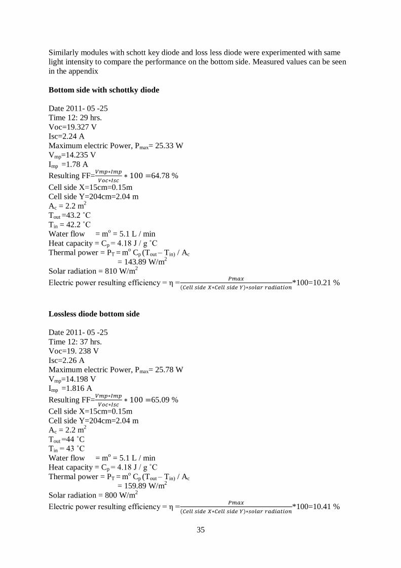
Bottom side of the module have been measured that was mainly affected by shading because
of gables. At 12: 29 Hrs, due to attachment of schottky on the bottom side the efficiency was
10.22% on the other hand, at 12: 37 Hrs, for the lossless diode attachment the efficiency was
reached 10.53 % that shows the improvement of the hybrid solar system efficiency.
As shadow affects the bottom side of the module due to gables so by pass diode get affected
at bottom side so comparison between schottky diode and lessloss diode can be seen through
bottom side results as shown in the Table 5.
Bottom Side Date Time Pmax(W) FF % Efficiency
Schottky diode
25/5/11 12:29 25.33 0.64 10.21
Loss diode 25/5/11 12:37 25.78 0.65 10.41
Table 5. Calculation results for new loss less diode by Micro Semi and schottky diode at bot-
tom sides of modules.
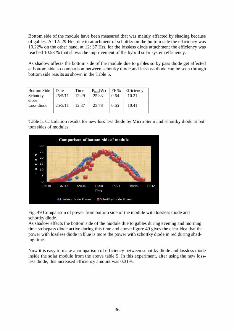
Fig. 49 Comparison of power from bottom side of the module with lossless diode and
schottky diode.
As shadow effects the bottom side of the module due to gables during evening and morning
time so bypass diode active during this time and above figure 49 gives the clear idea that the
power with lossless diode in blue is more the power with schottky diode in red during shad-
ing time.
Now it is easy to make a comparison of efficiency between schottky diode and lossless diode
inside the solar module from the above table 5. In this experiment, after using the new loss-
less diode, this increased efficiency amount was 0.31%.
37
Number of diodes Price per piece
1-200 33 SEK
200-10000 20 SEK
Price of the new lossless diode that will be used inside the
solarus module
Number of diode Price per piece
01-99 14.52 SEK
100-249 12.38SEK
250-999 9.71SEK
More than 1000 8.06 SEK
Price of the schottky diode that are using inside
the solarus module
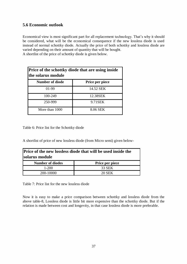
5.6 Economic outlook
Economical view is most significant part for all replacement technology. That’s why it should
be considered, what will be the economical consequence if the new lossless diode is used
instead of normal schottky diode. Actually the price of both schottky and lossless diode are
varied depending on their amount of quantity that will be bought.
A shortlist of the price of schottky diode is given below.
Table 6: Price list for the Schottky diode
A shortlist of price of new lossless diode (from Micro semi) given below-
Table 7: Price list for the new lossless diode
Now it is easy to make a price comparison between schottky and lossless diode from the
above table-8, Lossless diode is little bit more expensive than the schottky diode. But if the
relation is made between cost and longevity, in that case lossless diode is more preferable.
38
6. Discussion
The main purpose of this study was to compare the results in terms of output power and effi-
ciency using schottky diode and new loss less diode by the company Micro Semi, in thermal
solar hybrid collector. The PVT collector used in experiments or data collection was manu-
factured by Solarus AB Sweden, which integrate heat and electricity by using the same ser-
vice area, and can operate at its peak electrical output by reducing overheating problem.
Shading can cause the power loss or hot spot creation. To minimize shading effects by pass
diode concept is used to remove power dissipation, traditionally schottky diode is used which
has more forward voltage drops decrease the efficiency or electrical power put of the system.
To overcome Micro Semi designed new lossless by pass diode with low forward voltage drop
which are 50mV at 10 A generates 10°C temperature rise and can fully operate from - 65°C
to + 165°C and reverse Microsemi diode can block 22 V at less than 100 °C leakage current
without break down.
So experiments were conducted to investigate the power output and efficiency of the system
by using both, new lossless diode by Micro Semi and schottky diode and to compare the re-
sults. IV curves were obtained by using logger and solar radiations are measured by using the
Melacs control system. The solar radiations are collected from the top side of the solar collec-
tor, on 12th of June with schottky diode and with new lossless diode. Only the peak values are
considered between every 500 output value. For the top side 34.8 W and 37.3 W maximum
output power was measured for schottky diode and new lossless diode with electrical conver-
sion efficiency 13.39 % and 14.53 % respectively, similarly from the bottom side of the sys-
tem maximum power at 25th May was 25.33 W with schottky diode and for lossless diode
power output at was 25.78 W with electrical conversion efficiency 10.21% and 10.41% for
schottky and lossless diode module respectively.
Shading caused at the bottom of the collector because of gables which decrease the power
output. Because the reflectors cannot work properly to reflect light and the current of the
module go through by pass diode which cause the forward voltage drop results in reduce
power output.
After using the lossless diode as a substitute of schottky diode, the total output power was
Increased that’s why we got more efficiency from this one module.

39
7. Conclusions
In order to have a précised result many data have been collected from the outdoor test even
though it was very difficult to make an exact result because of the large range of data. After
accomplished all data the result has been reflected that the module with lossless diode has
more out power and electrical conversion efficiency as compared to module with schottky
diode at the bottom side where shadow is the problem because of the gables. Now, it can be
concluded that lossless diode is more effective than the traditional schottky diode.
LX2400 Micro semi new lossless diode operating efficiency and power output is more by
using the normal schottky diode.
In terms of cost and life time, lossless diode is more expensive than schottky diode but the
lifetime is relatively high then the schottky diode .Considering this all new result solar energy
technology can turn to a new way where lossless diode will be used instead of schottky diode
inside the solar module.

40
References
[1] Oksolar.com; Diodes in PV system, Bypass diode [On line] (Update 1988)
Available at: http://www.oksolar.com/technical/diodes_in_pv_systems.htm
(Accessed 30April 2011).
[2] Eurems; Bypass diode [On line]
Available at: http://www.eurems.com/links-topics/technical-info/bypass-diodes
(Accessed 02 May 2011)
[3] Solar energy facts [Online] (Update 2010).
Available at: http://solarenergyfactsblog.com/solar-energy-diagram/
(Accessed 04 May 2011)
[4] Atmospheric Effects on Incoming Solar Radiation [Online] (Update 2006)
Available at: http://www.physicalgeography.net/fundamentals/7f.html
(Accessed 07 May 2011)
[5] Solar-facts.com; how does a Solar Cell Work? The Complete Module
[Online] (Update)
Available at: http://www.solar-facts.com/panels/how-panels-work.php
(Accessed 07 May 2011)
[6] Solar-facts.com; The Complete Module [Online]
Available at: http://www.solar-facts.com/panels/panel-construction.php
(Accessed 08 May 2011)
[7] D. S. Pamplona., R. Rodriguez. “Dynamic modelling of hybrid PV/Thermal solar system
for hydrogen production”, Nov 2008
(Accessed 09 May 2011)
[8] Photovoltaic system; two approaches for using PV’s [Online](Update 2011)
Available at: http://photovoltaics.sustainablesources.com/#INTRO
(Accessed 12 May 2011)
[9] Solarus AB; Hybrid system [Online] (Update)
Available at: http://www.solarus.se/hybrid.html
(Accessed 12 May 2011)
[10] S.A. Kalogirou, Y.Tripanagnostopoulos. “Hybrid PV/T solar systems for domestic hot
water and electricity production”; Energy Conversion and Management 47 (2006) 3368–
3382.
[11] Y. Tripanagnostopoulos., M. souliotis, R. Battisti., A. Corrado “Application Aspects
Of Hybrid PV/T Solar System”
[12]. Apex solar; Types of shading [online](Update 2010)
Available at: http://www.apex-solar.co.uk/shading.htm
(Accessed 15 May 2011)
[13]. Enviroharvest Inc; shading [Online](Update 2011)
Available at: http://www.enviroharvest.ca/pv_shading.htm
(Accessed 16 May 2011)
[14]. Civic solar [Online](Update 2011)
Available at: http://www.civicsolar.com/forum/9824/what-bypass-diode
(Accessed 15 May 2011)
[15]. Molen Broek, D.w Waddington, K.A. Emery, National Renewable Energy Laboratory
(Formally the solar energy research institute golden Colorado)Hot Spot Susceptibility and
testing Of PV modules CH2953-8/91/0000-0547 1991 IEEE
[16] Pvcdrom.pveducation.org
Available at: http://pvcdrom.pveducation.org/MODULE/HotSpot.htm

41
(Accessed 24 May 2011)
[17]. Hot spot investigations on PV modules
Available at: New Concepts for a test standard and consequences for module design with
respect to bypass diodes
-By W. Herrmann, W. Wiesner, W. Vaaßen TÜV Rheinland Sicherheit und Umweltschutz
GmbH D-51101 Cologne, Germany
[18]. Operational behaviour of commercial solar cells under reverse biased conditions -by
W. Herrmann, M. Adrian, W. Wiesner TÜV Rheinland Sicherheit und Umweltschutz
GmbH
[19]. Hot-Spot heating and bypass diode [Online]
Available at: http://www.southalabama.edu/engineering/ece/faculty/akhan/Courses/EE590-
Renewable/supporting%20meterial/PVDevices/pvcdrom/Ch06/Hotspot.htm
(Accessed 28 May 2011)
[20] Schottky diode
Available at: http://en.wikipedia.org/wiki/Schottky_diode
(Accessed 30 May 2011)
[21] Schottky diode; Comparison of schottky diode and pn junction diode [Online]
(Update 2011)
Available at: http://en.citizendium.org/wiki/Schottky_diode
(Accessed 05 June 2011)
[22] Theory of I-V characterization, Short circuit current, open circuit voltage, Maximum
Power, Fill factor, Efficiency, Shunt and series resistance,[Online](Update 2009)
Available at: http://zone.ni.com/devzone/cda/tut/p/id/7230
(Accessed 28 June 2011)
[23] High current density surface mount trench MOS barrier schottky rectifier, Primary speci-
fication, Electrical characteristics, Rating and characteristics curve [Online] (Update 2011)
Available at: http://www.vishay.com/docs/88981/v12p10.pdf
(Accessed 14 July 2011)
[24] The Ideal solar bypass solution, LX2400, Product highlight,(Update 2010)
Available at: Solar solution by Micro Semi Company.
[25] J. Gomes, N. Stenlund, S. Larsson, B. Karlson, Elforsk report [ Skriv rapportner ]
Utveckling av hybrid Mareco Solfångare.
42
List of figure
Fig 1.By-pass diode technology
Fig 2.Incoming solar radiation on Atmosphere and Earth surface
Fig 3.Grid connected PV system diagram
Fig 4.Silicon wafer of solar cell
Fig 5.Solar cell working principle
Fig 6.Solar cell making system
Fig 7.Complete solar cell
Fig 8.Hybrid solar System
Fig 9.Shading on solar panel
Fig 10.Full-cell shading that can reduce PV module power to zero.
Fig 11.Full cell shading that can reduce PV module power to half.
Fig 12.Partial-cell shading that can reduce PV module power to half.
Fig 13.Shading cell that produce hot spot
Fig 14.Effect of hot spot on solar panel
Fig 15.Equivalent circuit of solar cell with bypass diode
Fig 16.I-V curve of solar cell with bypass diode
Fig 17.Schottky diode
Fig 18.Schottky diode schematic symbol
Fig 19.I-V curve for pn junction diode and schottky diode.
Fig 20.I-V curve of Solar cell and electrical diagram
Fig 21.Equivalent circuit of solar cell
Fig 22.I-V curve of solar cell
Fig 23. Maximum power for PV cell
Fig 24.Fill factor from the I-V curve
Fig25. Effect of diverging RS and RSH
Fig26. Temperature effect on I-V curve
Fig 27.Solarus Hybrid solar collector
Fig 28.Double absorber and aluminium reflector
Fig 29.Efficiency at different irradiation angles
Fig 30.Solarus CPC-T modutky diodele with Schottky diode
Fig 31.Schottky diode from VISHAY
Fig 32. Maximum forward current duration curve
Fig 33. Forward power loss curve
Fig 34. Typical Instantaneous forward curves
Fig 35.Loss less Micro Semi Solar bypasses diode.
Fig 36. LX 2400 on the solar string system
Fig 37. Typical VFWD Vs Current
Fig 38.Typical forward voltage at 10A VS t
Fig 39 .Current VS forward voltage for Schottky diode and the lossless diode
Fig 40 .Reverse leakage (µA) VS temperature
Fig 41. Electrical Power out Put for the top side of the module at 12th
June at Älvkarleö.
Fig 42 measured I-Vcurves for the cells on the top side of the module during the period 09:00
to 14:00 Hrs , 2011-06-12.
Fig 43. Electrical power out for the top side of the module, at 12st June 2011, Älvkarleö
Fig 44, measured I-V curve for the cells on the top side of the module loss less diode during
period 0800 to 1300 hrs at 2011-06-12
Fig 45. Electrical power out put at bottom side, 25th May 2011, Älvkarleö.
43
Fig 46. I-V curve of Solarus module bottom side when schottky diode was connected during
period 0800 to 1300 hrs. at 2011-05-25.
Fig 47. Electrical power out put at bottom side, 25th May 2011, Älvkarleö
Fig 48. I-V curve of Solarus module bottom side when lossless diode was connected during
0800 to 1300 Hrs. at 2011-05-25.
Fig. 49 Comparison of power from bottom side of the module with lossless diode and
schottky diode.

44
List of Table
Table 1: Primary Specification of schottky diode.
Table 2. Electrical Characteristics of schottky diode.
Table 3. Function pin description.
Table 4.Electrical characteristics of lossless diode.
Table 5: calculation results for schott key diode new loss less diode by Microsemi.
Table 6: Price list for the schottky diode.
Table 7: Price list for the new lossless diode.
45
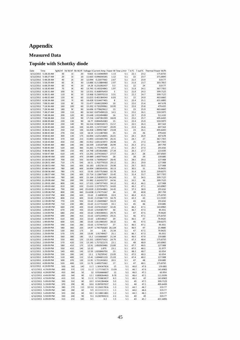
Appendix
Measured Data
Topside with Schottky diode
Date Time RgW/m ² Rd W/m ² Rb W/m ² Voltage V Current Amp Power W Flow L/min T in ?C T out ?C Thermal Power W/m ² 6/12/2011 5:28:26 AM 30 10 20 9.663 0.116940909 1.13 5.1 22.1 23.2 175.8735 6/12/2011 5:38:27 AM 20 10 10 11.663 0.096030181 1.12 5.1 22 23.7 271.8045 6/12/2011 5:48:28 AM 40 20 20 12.094 0.22077063 2.67 5.1 21.9 23.9 319.77 6/12/2011 5:58:29 AM 60 30 30 13.886 0.213884488 2.97 5.1 21.8 23.7 303.7815 6/12/2011 6:08:29 AM 60 40 20 14.28 0.231092437 3.3 5.1 22 24 319.77 6/12/2011 6:18:30 AM 70 30 40 13.745 0.143324845 1.97 5.1 21.8 24.1 367.7355 6/12/2011 6:28:31 AM 100 50 50 13.551 0.368976459 5 5.1 21.8 24.3 399.7125 6/12/2011 6:38:31 AM 110 60 50 13.968 0.236970218 3.31 5.1 22.2 24.7 399.7125 6/12/2011 6:48:32 AM 120 60 60 15.023 0.401384544 6.03 5.1 22 24.9 463.6665 6/12/2011 6:58:34 AM 130 70 60 14.428 0.554477405 8 5.1 22.4 25.1 431.6895 6/12/2011 7:08:35 AM 150 80 70 15.477 0.646120049 10 5.1 22.6 25.4 447.678 6/12/2011 7:18:36 AM 160 100 60 15.202 0.720299961 10.95 5.1 22.8 25.8 479.655 6/12/2011 7:28:36 AM 180 90 90 16.696 0.778629612 13 5.1 23 25.9 463.6665 6/12/2011 7:38:37 AM 190 110 80 16.562 0.875498128 14.5 5.1 22.6 26.1 559.5975 6/12/2011 7:48:38 AM 200 120 80 15.648 1.022494888 16 5.1 22.7 25.9 511.632 6/12/2011 7:58:38 AM 210 120 90 17.216 1.047281599 18.03 5.1 22.6 25.7 495.6435 6/12/2011 8:08:39 AM 220 130 90 16.77 0.894454383 15 5.1 22.4 25.9 559.5975 6/12/2011 8:18:39 AM 230 140 90 16.554 0.940558173 15.57 5.1 22.5 26.3 607.563 6/12/2011 8:28:40 AM 240 140 100 16.205 1.237272447 20.05 5.1 22.8 26.6 607.563 6/12/2011 8:38:41 AM 250 150 100 16.458 1.399927087 23.04 5.1 23 26.1 495.6435 6/12/2011 8:48:42 AM 270 150 120 16.54 1.511487304 25 5.1 23 26 479.655 6/12/2011 8:58:42 AM 300 130 170 16.004 1.625218695 26.01 5.1 24.1 26.9 447.678 6/12/2011 9:08:42 AM 370 160 210 15.893 1.655445794 26.31 5.1 24.7 27 367.7355 6/12/2011 9:18:43 AM 430 150 280 15.952 1.691323972 26.98 5.1 25 27.3 367.7355 6/12/2011 9:28:44 AM 480 140 340 16.339 1.65187588 26.99 5.1 25.3 27.1 287.793 6/12/2011 9:38:45 AM 520 160 360 15.261 1.775768298 27.1 5.1 25.7 27.3 255.816 6/12/2011 9:48:46 AM 590 150 440 14.748 1.853810686 27.34 5.1 26.3 27.7 223.839 6/12/2011 9:58:47 AM 610 140 470 13.291 2.074336017 27.57 5.1 26.7 28 207.8505 6/12/2011 10:08:49 AM 630 160 470 19.989 1.400770424 28 5.1 28 29 159.885 6/12/2011 10:18:50 AM 700 150 550 16.436 1.730956437 28.45 5.1 28.5 29.3 127.908 6/12/2011 10:28:51 AM 710 170 540 16.51 1.763779528 29.12 5.1 29.1 29.9 127.908 6/12/2011 10:38:53 AM 760 160 600 16.183 1.85256133 29.98 5.1 29.7 30.5 127.908 6/12/2011 10:48:54 AM 780 180 600 16.004 1.882654336 30.13 5.1 30.5 31 79.9425 6/12/2011 10:58:56 AM 780 170 610 15.93 2.057752668 32.78 5.1 31.4 32.9 239.8275 6/12/2011 11:08:57 AM 790 190 600 15.714 2.128675067 33.45 5.1 31.4 33.7 367.7355 6/12/2011 11:18:59 AM 780 180 600 15.164 2.258309153 34.245 5.1 32 34.5 399.7125 6/12/2011 11:29:00 AM 790 200 590 15.982 2.162432737 34.56 5.1 33.5 36 399.7125 6/12/2011 11:39:01 AM 800 190 610 17.521 1.947377433 34.12 5.1 45.3 46.1 127.908 6/12/2011 11:49:03 AM 810 180 630 15.633 2.227979275 34.83 5.1 46.2 47.1 143.8965 6/12/2011 11:59:04 AM 790 200 640 15.6339 2.203544861 34.45 5.1 37.3 38.9 255.816 6/12/2011 12:09:06 PM 800 190 660 15.6338 2.174775167 34 5.1 39 40.8 287.793 6/12/2011 12:19:07 PM 800 200 630 15.63 2.16890595 33.9 5.1 40.4 41.5 175.8735 6/12/2011 12:29:09 PM 800 210 600 15.63 2.225847729 34.79 5.1 42.3 43 111.9195 6/12/2011 12:39:09 PM 770 220 550 15.63 2.126039667 33.23 5.1 43 44.6 255.816 6/12/2011 12:49:09 PM 710 230 480 15.63 2.117722329 33.1 5.1 45 46 159.885 6/12/2011 12:59:09 PM 660 230 430 15.63 2.076135637 32.45 5.1 46.2 47.1 143.8965 6/12/2011 1:09:09 PM 670 240 430 15.63 1.919385797 30 5.1 46.7 47.3 95.931 6/12/2011 1:19:09 PM 680 250 430 15.63 1.903390915 29.75 5.1 47 47.5 79.9425 6/12/2011 1:29:09 PM 690 280 410 15.63 1.875239923 29.31 5.1 46 47.1 175.8735 6/12/2011 1:39:09 PM 610 300 310 15.63 1.85540627 29 5.1 46.5 47 79.9425 6/12/2011 1:49:09 PM 600 320 280 15.63 1.811900192 28.32 5.1 46 47.5 239.8275 6/12/2011 1:59:09 PM 590 330 260 15.63 1.727447217 27 5.1 46.5 47.1 95.931 6/12/2011 2:09:09 PM 580 360 220 14.97 1.745758183 26.134 5.1 46.9 47 15.9885 6/12/2011 2:19:09 PM 530 360 170 14 1.81 25.34 5.1 47 47.5 79.9425 6/12/2011 2:29:09 PM 570 370 200 13.09 1.91749427 25.1 5.1 46.7 47.3 95.931 6/12/2011 2:39:09 PM 560 380 180 13.2 1.616666667 21.34 5.1 46.9 47.9 159.885 6/12/2011 2:49:09 PM 550 400 150 13.331 1.859575426 24.79 5.1 47.3 48.4 175.8735 6/12/2011 2:59:09 PM 570 420 150 13.145 1.757322176 23.1 5.1 48 48.9 143.8965 6/12/2011 3:09:09 PM 580 410 170 12.91 1.850503486 23.89 5.1 47.7 48.5 127.908 6/12/2011 3:19:09 PM 550 410 140 12.32 1.875 23.1 5.1 47.9 48.1 31.977 6/12/2011 3:29:09 PM 540 400 140 12.59 1.826846704 23 5.1 48.3 48.7 63.954 6/12/2011 3:39:09 PM 530 390 140 13.1 1.76259542 23.09 5.1 47.9 48.3 63.954 6/12/2011 3:49:09 PM 510 400 110 12.41 1.694601128 21.03 5.1 47.4 48.2 127.908 6/12/2011 3:59:09 PM 500 370 130 11.91 1.721242653 20.5 5.1 47 48 159.885 6/12/2011 4:09:09 PM 520 400 120 11.73 1.449275362 17 5.1 47 48.1 175.8735 6/12/2011 4:19:09 PM 500 360 140 11.5 1.304347826 15 5.1 46.8 47.8 159.885 6/12/2011 4:29:09 PM 490 370 120 11.12 1.177158273 13.09 5.1 46.7 47.6 143.8965 6/12/2011 4:39:09 PM 410 360 50 12 0.916666667 11 5.1 46.9 47.3 63.954 6/12/2011 4:49:09 PM 420 340 80 12.1 0.808264463 9.78 5.1 46.4 47.1 111.9195 6/12/2011 4:59:09 PM 410 320 90 11.31 0.733863837 8.3 5.1 46.1 47 143.8965 6/12/2011 5:09:09 PM 390 310 80 10.9 0.541284404 5.9 5.1 45 47.5 399.7125 6/12/2011 5:19:09 PM 370 290 80 10.8 0.287037037 3.1 5.1 44 47.1 495.6435 6/12/2011 5:29:09 PM 380 270 110 10.316 0.126017836 1.3 5.1 44.7 46.7 319.77 6/12/2011 5:39:09 PM 340 280 60 9.9 0.111111111 1.1 5.1 44.6 46.6 319.77 6/12/2011 5:49:09 PM 320 260 60 10.1 0.118811881 1.2 5.1 44.3 46.3 319.77 6/12/2011 5:59:09 PM 330 240 90 9.1 0.230769231 2.1 5.1 43 45 319.77 6/12/2011 6:09:09 PM 310 210 100 9.5 0.2 1.9 5.1 43 45.7 431.6895

46
47
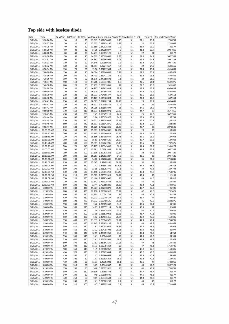
Top side with lossless diode
Date Time Rg W/m² Rd W/m² Rb W/m² Voltage V Current Amp Power W Flow L/min T in ˚C T out ˚C Thermal Power W/m²
6/21/2011 5:28:26 AM 30 10 20 13.313 0.131450462 1.75 5.1 22.1 23.2 175.8735
6/21/2011 5:38:27 AM 20 10 10 13.633 0.138634196 1.89 5.1 22 23.7 271.8045
6/21/2011 5:48:28 AM 40 20 20 13.559 0.140128328 1.9 5.1 21.9 23.9 319.77
6/21/2011 5:58:29 AM 60 30 30 14.25 0.140350877 2 5.1 21.8 23.7 303.7815
6/21/2011 6:00:00 AM 60 40 20 14.733 0.156112129 2.3 5.1 22 24 319.77
6/21/2011 6:18:30 AM 70 30 40 14.919 0.160198405 2.39 5.1 21.8 24.1 367.7355
6/21/2011 6:28:31 AM 100 50 50 14.362 0.212365966 3.05 5.1 21.8 24.3 399.7125
6/21/2011 6:38:31 AM 110 60 50 14.146 0.27569631 3.9 5.1 22.2 24.7 399.7125
6/21/2011 6:48:32 AM 120 60 60 16.517 0.27244657 4.5 5.1 22 24.9 463.6665
6/21/2011 6:58:34 AM 130 70 60 15.96 0.307017544 4.9 5.1 22.4 25.1 431.6895
6/21/2011 7:00:00 AM 150 80 70 16.094 0.359140052 5.78 5.1 22.6 25.4 447.678
6/21/2011 7:18:36 AM 160 100 60 16.413 0.359471151 5.9 5.1 22.8 25.8 479.655
6/21/2011 7:28:36 AM 180 90 90 15.878 0.447159592 7.1 5.1 23 25.9 463.6665
6/21/2011 7:38:37 AM 190 110 80 17.788 0.500337306 8.9 5.1 22.6 26.1 559.5975
6/21/2011 7:48:38 AM 200 120 80 17.439 0.688112851 12 5.1 22.7 25.9 511.632
6/21/2011 7:58:38 AM 210 120 90 16.837 0.819623448 13.8 5.1 22.6 25.7 495.6435
6/21/2011 8:00:00 AM 220 130 90 16.629 0.877984244 14.6 5.1 22.4 25.9 559.5975
6/21/2011 8:18:39 AM 230 140 90 16.733 0.764955477 12.8 5.1 22.5 26.3 607.563
6/21/2011 8:28:40 AM 240 140 100 17.127 0.636422024 10.9 5.1 22.8 26.6 607.563
6/21/2011 8:38:41 AM 250 150 100 18.387 0.912601294 16.78 5.1 23 26.1 495.6435
6/21/2011 8:48:42 AM 270 150 120 16.227 1.103099772 17.9 5.1 23 26 479.655
6/21/2011 8:58:42 AM 300 130 170 16.235 1.293501694 21 5.1 24.1 26.9 447.678
6/21/2011 9:00:00 AM 370 160 210 16.673 1.431655971 23.87 5.1 24.7 27 367.7355
6/21/2011 9:18:43 AM 430 150 280 15.9 1.553459119 24.7 5.1 25 27.3 367.7355
6/21/2011 9:28:44 AM 480 140 340 15.96 1.560150376 24.9 5.1 25.3 27.1 287.793
6/21/2011 9:38:45 AM 520 160 360 20.271 1.239702037 25.13 5.1 25.7 27.3 255.816
6/21/2011 9:48:46 AM 590 150 440 15.811 1.631142875 25.79 5.1 26.3 27.7 223.839
6/21/2011 9:58:47 AM 610 140 470 15.729 1.703223345 26.79 5.1 26.7 28 207.8505
6/21/2011 10:00:00 AM 630 160 470 15.811 1.716146986 27.134 5.1 28 29 159.885
6/21/2011 10:18:50 AM 700 150 550 15.885 1.755744413 27.89 5.1 28.5 29.3 127.908
6/21/2011 10:28:51 AM 710 170 540 15.596 1.824185689 28.45 5.1 29.1 29.9 127.908
6/21/2011 10:38:53 AM 760 160 600 16.51 1.754694125 28.97 5.1 29.7 30.5 127.908
6/21/2011 10:48:54 AM 780 180 600 15.811 1.862627285 29.45 5.1 30.5 31 79.9425
6/21/2011 10:58:56 AM 780 170 610 15.707 1.916343032 30.1 5.1 31.4 32.9 239.8275
6/21/2011 11:00:00 AM 790 190 600 15.781 2.01381408 31.78 5.1 31.4 33.7 367.7355
6/21/2011 11:18:59 AM 780 180 600 17.105 1.890675241 32.34 5.1 32 34.5 399.7125
6/21/2011 11:29:00 AM 790 200 590 16.287 2.142813287 34.9 5.1 33.5 36 399.7125
6/21/2011 11:39:01 AM 800 190 610 14.02 2.537660485 35.578 5.1 35 36.7 271.8045
6/21/2011 11:49:03 AM 810 180 630 15.045 2.41409106 36.32 5.1 36 37 159.885
6/21/2011 11:59:04 AM 840 200 640 15.7 2.375987261 37.303 5.1 37.3 38.9 255.816
6/21/2011 12:00:00 PM 850 190 660 13.15 2.821292776 37.1 5.1 39 40.8 287.793
6/21/2011 12:19:07 PM 830 200 630 14.198 2.573813213 36.543 5.1 40.4 41.5 175.8735
6/21/2011 12:29:09 PM 810 210 600 13.009 2.776539319 36.12 5.1 42.3 43 111.9195
6/21/2011 12:39:09 PM 770 220 550 12.466 2.887854966 36 5.1 43 44.6 255.816
6/21/2011 12:49:09 PM 710 230 480 13.142 2.723329782 35.79 5.1 45 46 159.885
6/21/2011 12:59:09 PM 660 230 430 13.44 2.707589286 36.39 5.1 46.2 47.1 143.8965
6/21/2011 1:00:00 PM 670 240 430 11.827 2.997378879 35.45 5.1 46.7 47.3 95.931
6/21/2011 1:19:09 PM 680 250 430 12.198 2.879160518 35.12 5.1 47 47.5 79.9425
6/21/2011 1:29:09 PM 690 280 410 13,133 0.00281733 37 5.1 46 47.1 175.8735
6/21/2011 1:39:09 PM 610 300 310 13,271 0.002705147 35.9 5.1 46.5 47 79.9425
6/21/2011 1:49:09 PM 600 320 280 14,672 0.002406625 35.31 5.1 46 47.5 239.8275
6/21/2011 1:59:09 PM 590 330 260 15.2 2.296052632 34.9 5.1 46.5 47.1 95.931
6/21/2011 2:00:00 PM 580 360 220 14.97 2.278557114 34.11 5.1 46.9 47 15.9885
6/21/2011 2:19:09 PM 530 360 170 14 2.421428571 33.9 5.1 47 47.5 79.9425
6/21/2011 2:29:09 PM 570 370 200 13.09 2.538579068 33.23 5.1 46.7 47.3 95.931
6/21/2011 2:39:09 PM 560 380 180 13.2 2.404545455 31.74 5.1 46.9 47.9 159.885
6/21/2011 2:49:09 PM 550 400 150 13.331 2.266146576 30.21 5.1 47.3 48.4 175.8735
6/21/2011 2:59:09 PM 570 420 150 13.145 2.274629137 29.9 5.1 48 48.9 143.8965
6/21/2011 3:00:00 PM 580 410 170 12.91 2.270333075 29.31 5.1 47.7 48.5 127.908
6/21/2011 3:19:09 PM 550 410 140 12.32 2.354707792 29.01 5.1 47.9 48.1 31.977
6/21/2011 3:29:09 PM 540 400 140 12.59 2.478157268 31.2 5.1 48.3 48.7 63.954
6/21/2011 3:39:09 PM 530 390 140 13.1 2.13740458 28 5.1 47.9 48.3 63.954
6/21/2011 3:49:09 PM 510 400 110 12.41 2.264302981 28.1 5.1 47.4 48.2 127.908
6/21/2011 3:59:09 PM 500 370 130 11.91 2.267842149 27.01 5.1 47 48 159.885
6/21/2011 4:00:00 PM 520 400 120 11.73 1.960784314 23 5.1 47 48.1 175.8735
6/21/2011 4:19:09 PM 500 360 140 11.5 1.826086957 21 5.1 46.8 47.8 159.885
6/21/2011 4:29:09 PM 490 370 120 11.12 1.708633094 19 5.1 46.7 47.6 143.8965
6/21/2011 4:39:09 PM 410 360 50 12 1.416666667 17 5.1 46.9 47.3 63.954
6/21/2011 4:49:09 PM 420 340 80 12.1 1.363636364 16.5 5.1 46.4 47.1 111.9195
6/21/2011 4:59:09 PM 410 320 90 11.31 1.42351901 16.1 5.1 46.1 47 143.8965
6/21/2011 5:00:00 PM 390 310 80 10.9 1.28440367 14 5.1 45 47.5 399.7125
6/21/2011 5:19:09 PM 370 290 80 10.8 0.925925926 10 5.1 46 47.1 175.8735
6/21/2011 5:29:09 PM 380 270 110 10.316 0.67855758 7 5.1 44.7 46.7 319.77
6/21/2011 5:39:09 PM 340 280 60 9.9 0.505050505 5 5.1 44.6 46.6 319.77
6/21/2011 5:49:09 PM 320 260 60 10.1 0.366336634 3.7 5.1 44.3 46.3 319.77
6/21/2011 5:59:09 PM 330 240 90 9.1 0.296703297 2.7 5.1 43 45 319.77
6/21/2011 6:00:00 PM 310 210 100 8.7 0.333333333 2.9 5.1 44 45.7 271.8045

48
Bottom side with Schottky diode
Date Time Rg W/m² Rd W/m² Rb W/m² Voltage V Current Amp Power W Flow L/minT out˚C T in ˚C Thermal Power W/m²
5/25/2011 5:28:26 AM 40 20 20 10.74 0.074487896 0.8 5.1 22.1 22.5 63.954
5/25/2011 5:38:27 AM 50 30 20 10.7 0.085046729 0.91 5.1 22 22.2 31.977
5/25/2011 5:48:28 AM 70 20 50 11.373 0.087927548 1 5.1 21.9 22.1 31.977
5/25/2011 5:58:29 AM 70 20 50 10.645 0.103334899 1.1 5.1 21.8 22.4 95.931
5/25/2011 6:08:29 AM 70 30 40 10.273 0.109023654 1.12 5.1 22 22.7 111.9195
5/25/2011 6:18:30 AM 80 20 60 10.905 0.114626318 1.25 5.1 21.8 22.8 159.885
5/25/2011 6:28:31 AM 80 20 60 10.697 0.125268767 1.34 5.1 21.8 22.8 159.885
5/25/2011 6:38:31 AM 80 30 50 10.957 0.123208908 1.35 5.1 22.2 22.7 79.9425
5/25/2011 6:48:32 AM 90 20 70 10.845 0.16505302 1.79 5.1 22 22.9 143.8965
5/25/2011 6:58:34 AM 90 30 60 10.377 0.170569529 1.77 5.1 22.4 23 95.931
5/25/2011 7:08:35 AM 100 20 80 10.459 0.173056698 1.81 5.1 22.6 23.2 95.931
5/25/2011 7:18:36 AM 90 40 50 10.109 0.210703334 2.13 5.1 22.8 23.4 95.931
5/25/2011 7:28:36 AM 100 40 60 9.849 0.293430805 2.89 5.1 23 23.6 95.931
5/25/2011 7:38:37 AM 110 40 70 9.641 0.369256301 3.56 5.1 22.6 23.1 79.9425
5/25/2011 7:48:38 AM 110 40 70 9.715 0.447246526 4.345 5.1 22.7 23.5 127.908
5/25/2011 7:58:38 AM 120 50 70 9.886 0.526502124 5.205 5.1 22.6 23 63.954
5/25/2011 8:08:39 AM 110 60 50 9.5 0.616842105 5.86 5.1 22.4 23.2 127.908
5/25/2011 8:18:39 AM 120 50 70 9.909 0.617620345 6.12 5.1 22.5 23 79.9425
5/25/2011 8:28:40 AM 130 50 80 10.102 0.690952287 6.98 5.1 22.8 23.6 127.908
5/25/2011 8:38:41 AM 130 40 90 9.909 0.73771319 7.31 5.1 23 24 159.885
5/25/2011 8:48:42 AM 140 50 90 15.47 0.510471881 7.897 5.1 23 24.1 175.8735
5/25/2011 8:58:42 AM 150 60 90 10.117 0.82138974 8.31 5.1 24.1 25 143.8965
5/25/2011 9:08:42 AM 180 70 110 10.652 0.858054825 9.14 5.1 24.7 25.3 95.931
5/25/2011 9:18:43 AM 200 80 120 11.589 0.880144965 10 5.1 25 26 159.885
5/25/2011 9:28:44 AM 220 100 120 11.001 0.958094719 10.54 5.1 25.3 26.1 127.908
5/25/2011 9:38:45 AM 250 120 130 11.574 0.855365474 9.9 5.1 25.7 27.3 255.816
5/25/2011 9:48:46 AM 270 140 130 12.131 0.870497074 10.56 5.1 26.3 27.7 223.839
5/25/2011 9:58:47 AM 290 150 140 17.98 0.667408231 12 5.1 26.7 28 207.8505
5/25/2011 10:08:49 AM 310 170 140 19.327 0.191442024 3.7 5.1 28 29 159.885
5/25/2011 10:18:50 AM 340 190 150 14.323 0.860154995 12.32 5.1 28.5 29.3 127.908
5/25/2011 10:28:51 AM 360 200 160 17.98 0.859621802 15.456 5.1 29.1 29.9 127.908
5/25/2011 10:38:53 AM 380 220 160 11.098 1.469634168 16.31 5.1 29.7 30.5 127.908
5/25/2011 10:48:54 AM 420 240 180 10.191 1.059758611 10.8 5.1 30.5 31 79.9425
5/25/2011 10:58:56 AM 460 260 200 9.805 1.427842937 14 5.1 31.4 32.9 239.8275
5/25/2011 11:08:57 AM 500 300 200 10.734 1.798024967 19.3 5.1 31.4 33.7 367.7355
5/25/2011 11:18:59 AM 530 320 210 19.327 1.190045015 23 5.1 32 34.5 399.7125
5/25/2011 11:29:00 AM 570 350 220 9.678 2.226286423 21.546 5.1 33.5 36 399.7125
5/25/2011 11:39:01 AM 600 370 230 11.3 1.938053097 21.9 5.1 35 36.7 271.8045
5/25/2011 11:49:03 AM 630 400 230 11.45 1.951091703 22.34 5.1 36 37 159.885
5/25/2011 11:59:04 AM 680 410 270 11.79 1.977099237 23.31 5.1 37.3 38.9 255.816
5/25/2011 12:09:06 PM 700 420 280 11.99 2.067556297 24.79 5.1 39 40.8 287.793
5/25/2011 12:19:07 PM 750 450 300 12.13 2.052761748 24.9 5.1 40.4 41.5 175.8735
5/25/2011 12:29:09 PM 810 490 320 14.235 1.779978925 25.338 5.1 42.3 43.2 143.8965
5/25/2011 12:39:09 PM 800 480 320 12.145 2.066694113 25.1 5.1 43 44.6 255.816
5/25/2011 12:49:09 PM 780 510 270 11.9 2.075630252 24.7 5.1 45 46 159.885
5/25/2011 12:59:09 PM 750 500 250 11.915 2.039446076 24.3 5.1 46.2 47.1 143.8965
5/25/2011 1:09:09 PM 720 510 210 11.13 2.066486972 23 5.1 46.7 47.3 95.931
5/25/2011 1:19:09 PM 700 530 170 11.3 2.221238938 25.1 5.1 47 47.5 79.9425
5/25/2011 1:29:09 PM 720 510 210 10.9 2.231192661 24.32 5.1 46 47.1 175.8735
5/25/2011 1:39:09 PM 710 520 190 10.762 2.241219104 24.12 5.1 46.5 47 79.9425
5/25/2011 1:49:09 PM 750 490 260 10.763 2.057047292 22.14 5.1 46 47.5 239.8275
5/25/2011 1:59:09 PM 730 480 250 9.1 2.212307692 20.132 5.1 46.5 47.1 95.931
5/25/2011 2:09:09 PM 720 470 250 9.324 2.006649507 18.71 5.1 46.9 47 15.9885
5/25/2011 2:19:09 PM 710 450 260 9.2 2.063043478 18.98 5.1 47 47.5 79.9425
5/25/2011 2:29:09 PM 700 470 230 9.302 1.971619007 18.34 5.1 46.7 47.3 95.931
5/25/2011 2:39:09 PM 650 450 200 9.93 1.735548842 17.234 5.1 46.9 47.9 159.885
5/25/2011 2:49:09 PM 620 420 200 10.1 1.926336634 19.456 5.1 47.3 48.4 175.8735
5/25/2011 2:59:09 PM 600 380 220 9.94 1.473943662 15 5.1 48 48.9 143.8965
5/25/2011 3:09:09 PM 580 350 230 9.678 1.43728043 13.91 5.1 47.7 48.5 127.908
5/25/2011 3:19:09 PM 570 330 240 9.917 1.454068771 14.42 5.1 47.9 48.1 31.977
5/25/2011 3:29:09 PM 510 310 200 10.741 1.272693418 13.67 5.1 48.3 48.7 63.954
5/25/2011 3:39:09 PM 470 280 190 10.109 1.274013256 13 5.1 47.9 48.3 63.954
5/25/2011 3:49:09 PM 440 260 180 10.34 0.989361702 10.23 5.1 47.4 48.2 127.908
5/25/2011 3:59:09 PM 380 290 90 10.17 1.11553589 11 5.1 47 48 159.885
5/25/2011 4:09:09 PM 320 270 50 10.398 1.015579919 10.56 5.1 47 48.1 175.8735
5/25/2011 4:19:09 PM 290 260 30 9.91 0.95358224 9.45 5.1 46.8 47.8 159.885
5/25/2011 4:29:09 PM 280 240 40 9,874 0.000740328 7.31 5.1 46.7 47.6 143.8965
5/25/2011 4:39:09 PM 280 230 50 9,541 0.000662404 6.32 5.1 46.9 47.3 63.954
5/25/2011 4:49:09 PM 250 200 50 9,872 0.000519652 5.13 5.1 46.4 47.1 111.9195
5/25/2011 4:59:09 PM 260 180 80 10,110 0.000418398 4.23 5.1 46.1 47 143.8965
5/25/2011 5:09:09 PM 270 160 110 9,345 0.000334938 3.13 5.1 45 47.5 399.7125
5/25/2011 5:19:09 PM 250 140 110 9,238 0.000313921 2.9 5.1 46 47.1 175.8735
5/25/2011 5:29:09 PM 230 120 110 8.99 0.233592881 2.1 5.1 44.7 45.3 95.931
5/25/2011 5:39:09 PM 240 110 130 9,871 0.000192483 1.9 5.1 44.6 45 63.954
5/25/2011 5:49:09 PM 260 90 170 9,100 0.000208791 1.9 5.1 44.3 45.3 159.885
5/25/2011 5:59:09 PM 230 80 150 8.9 0.21011236 1.87 5.1 43 44 159.885
5/25/2011 6:09:09 PM 210 60 150 8.21 0.225334957 1.85 5.1 44 44.1 15.9885
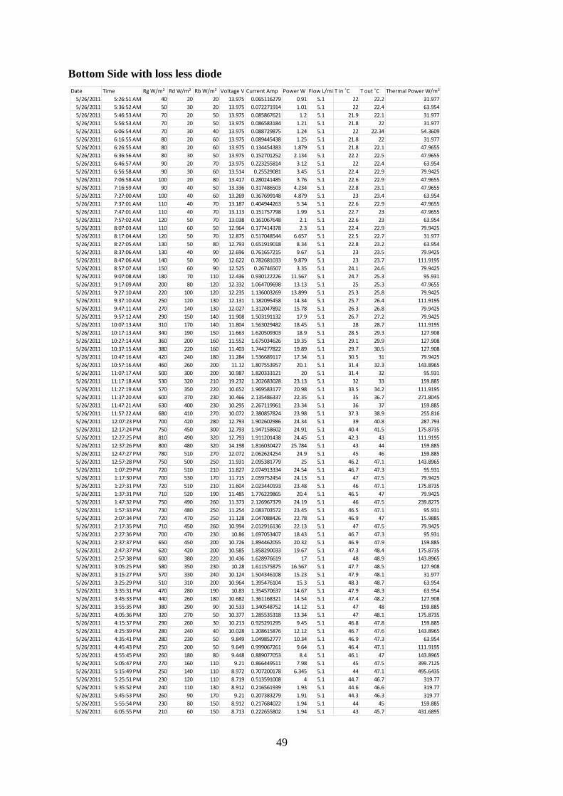
49
Bottom Side with loss less diode
Date Time Rg W/m² Rd W/m² Rb W/m² Voltage V Current Amp Power W Flow L/minT in ˚C T out ˚C Thermal Power W/m²
5/26/2011 5:26:51 AM 40 20 20 13.975 0.065116279 0.91 5.1 22 22.2 31.977
5/26/2011 5:36:52 AM 50 30 20 13.975 0.072271914 1.01 5.1 22 22.4 63.954
5/26/2011 5:46:53 AM 70 20 50 13.975 0.085867621 1.2 5.1 21.9 22.1 31.977
5/26/2011 5:56:53 AM 70 20 50 13.975 0.086583184 1.21 5.1 21.8 22 31.977
5/26/2011 6:06:54 AM 70 30 40 13.975 0.088729875 1.24 5.1 22 22.34 54.3609
5/26/2011 6:16:55 AM 80 20 60 13.975 0.089445438 1.25 5.1 21.8 22 31.977
5/26/2011 6:26:55 AM 80 20 60 13.975 0.134454383 1.879 5.1 21.8 22.1 47.9655
5/26/2011 6:36:56 AM 80 30 50 13.975 0.152701252 2.134 5.1 22.2 22.5 47.9655
5/26/2011 6:46:57 AM 90 20 70 13.975 0.223255814 3.12 5.1 22 22.4 63.954
5/26/2011 6:56:58 AM 90 30 60 13.514 0.25529081 3.45 5.1 22.4 22.9 79.9425
5/26/2011 7:06:58 AM 100 20 80 13.417 0.280241485 3.76 5.1 22.6 22.9 47.9655
5/26/2011 7:16:59 AM 90 40 50 13.336 0.317486503 4.234 5.1 22.8 23.1 47.9655
5/26/2011 7:27:00 AM 100 40 60 13.269 0.367699148 4.879 5.1 23 23.4 63.954
5/26/2011 7:37:01 AM 110 40 70 13.187 0.404944263 5.34 5.1 22.6 22.9 47.9655
5/26/2011 7:47:01 AM 110 40 70 13.113 0.151757798 1.99 5.1 22.7 23 47.9655
5/26/2011 7:57:02 AM 120 50 70 13.038 0.161067648 2.1 5.1 22.6 23 63.954
5/26/2011 8:07:03 AM 110 60 50 12.964 0.177414378 2.3 5.1 22.4 22.9 79.9425
5/26/2011 8:17:04 AM 120 50 70 12.875 0.517048544 6.657 5.1 22.5 22.7 31.977
5/26/2011 8:27:05 AM 130 50 80 12.793 0.651919018 8.34 5.1 22.8 23.2 63.954
5/26/2011 8:37:06 AM 130 40 90 12.696 0.761657215 9.67 5.1 23 23.5 79.9425
5/26/2011 8:47:06 AM 140 50 90 12.622 0.782681033 9.879 5.1 23 23.7 111.9195
5/26/2011 8:57:07 AM 150 60 90 12.525 0.26746507 3.35 5.1 24.1 24.6 79.9425
5/26/2011 9:07:08 AM 180 70 110 12.436 0.930122226 11.567 5.1 24.7 25.3 95.931
5/26/2011 9:17:09 AM 200 80 120 12.332 1.064709698 13.13 5.1 25 25.3 47.9655
5/26/2011 9:27:10 AM 220 100 120 12.235 1.136003269 13.899 5.1 25.3 25.8 79.9425
5/26/2011 9:37:10 AM 250 120 130 12.131 1.182095458 14.34 5.1 25.7 26.4 111.9195
5/26/2011 9:47:11 AM 270 140 130 12.027 1.312047892 15.78 5.1 26.3 26.8 79.9425
5/26/2011 9:57:12 AM 290 150 140 11.908 1.503191132 17.9 5.1 26.7 27.2 79.9425
5/26/2011 10:07:13 AM 310 170 140 11.804 1.563029482 18.45 5.1 28 28.7 111.9195
5/26/2011 10:17:13 AM 340 190 150 11.663 1.620509303 18.9 5.1 28.5 29.3 127.908
5/26/2011 10:27:14 AM 360 200 160 11.552 1.675034626 19.35 5.1 29.1 29.9 127.908
5/26/2011 10:37:15 AM 380 220 160 11.403 1.744277822 19.89 5.1 29.7 30.5 127.908
5/26/2011 10:47:16 AM 420 240 180 11.284 1.536689117 17.34 5.1 30.5 31 79.9425
5/26/2011 10:57:16 AM 460 260 200 11.12 1.807553957 20.1 5.1 31.4 32.3 143.8965
5/26/2011 11:07:17 AM 500 300 200 10.987 1.820333121 20 5.1 31.4 32 95.931
5/26/2011 11:17:18 AM 530 320 210 19.232 1.202683028 23.13 5.1 32 33 159.885
5/26/2011 11:27:19 AM 570 350 220 10.652 1.969583177 20.98 5.1 33.5 34.2 111.9195
5/26/2011 11:37:20 AM 600 370 230 10.466 2.135486337 22.35 5.1 35 36.7 271.8045
5/26/2011 11:47:21 AM 630 400 230 10.295 2.267119961 23.34 5.1 36 37 159.885
5/26/2011 11:57:22 AM 680 410 270 10.072 2.380857824 23.98 5.1 37.3 38.9 255.816
5/26/2011 12:07:23 PM 700 420 280 12.793 1.902602986 24.34 5.1 39 40.8 287.793
5/26/2011 12:17:24 PM 750 450 300 12.793 1.947158602 24.91 5.1 40.4 41.5 175.8735
5/26/2011 12:27:25 PM 810 490 320 12.793 1.911201438 24.45 5.1 42.3 43 111.9195
5/26/2011 12:37:26 PM 800 480 320 14.198 1.816030427 25.784 5.1 43 44 159.885
5/26/2011 12:47:27 PM 780 510 270 12.072 2.062624254 24.9 5.1 45 46 159.885
5/26/2011 12:57:28 PM 750 500 250 11.931 2.095381779 25 5.1 46.2 47.1 143.8965
5/26/2011 1:07:29 PM 720 510 210 11.827 2.074913334 24.54 5.1 46.7 47.3 95.931
5/26/2011 1:17:30 PM 700 530 170 11.715 2.059752454 24.13 5.1 47 47.5 79.9425
5/26/2011 1:27:31 PM 720 510 210 11.604 2.023440193 23.48 5.1 46 47.1 175.8735
5/26/2011 1:37:31 PM 710 520 190 11.485 1.776229865 20.4 5.1 46.5 47 79.9425
5/26/2011 1:47:32 PM 750 490 260 11.373 2.126967379 24.19 5.1 46 47.5 239.8275
5/26/2011 1:57:33 PM 730 480 250 11.254 2.083703572 23.45 5.1 46.5 47.1 95.931
5/26/2011 2:07:34 PM 720 470 250 11.128 2.047088426 22.78 5.1 46.9 47 15.9885
5/26/2011 2:17:35 PM 710 450 260 10.994 2.012916136 22.13 5.1 47 47.5 79.9425
5/26/2011 2:27:36 PM 700 470 230 10.86 1.697053407 18.43 5.1 46.7 47.3 95.931
5/26/2011 2:37:37 PM 650 450 200 10.726 1.894462055 20.32 5.1 46.9 47.9 159.885
5/26/2011 2:47:37 PM 620 420 200 10.585 1.858290033 19.67 5.1 47.3 48.4 175.8735
5/26/2011 2:57:38 PM 600 380 220 10.436 1.628976619 17 5.1 48 48.9 143.8965
5/26/2011 3:05:25 PM 580 350 230 10.28 1.611575875 16.567 5.1 47.7 48.5 127.908
5/26/2011 3:15:27 PM 570 330 240 10.124 1.504346108 15.23 5.1 47.9 48.1 31.977
5/26/2011 3:25:29 PM 510 310 200 10.964 1.395476104 15.3 5.1 48.3 48.7 63.954
5/26/2011 3:35:31 PM 470 280 190 10.83 1.354570637 14.67 5.1 47.9 48.3 63.954
5/26/2011 3:45:33 PM 440 260 180 10.682 1.361168321 14.54 5.1 47.4 48.2 127.908
5/26/2011 3:55:35 PM 380 290 90 10.533 1.340548752 14.12 5.1 47 48 159.885
5/26/2011 4:05:36 PM 320 270 50 10.377 1.285535318 13.34 5.1 47 48.1 175.8735
5/26/2011 4:15:37 PM 290 260 30 10.213 0.925291295 9.45 5.1 46.8 47.8 159.885
5/26/2011 4:25:39 PM 280 240 40 10.028 1.208615876 12.12 5.1 46.7 47.6 143.8965
5/26/2011 4:35:41 PM 280 230 50 9.849 1.049852777 10.34 5.1 46.9 47.3 63.954
5/26/2011 4:45:43 PM 250 200 50 9.649 0.999067261 9.64 5.1 46.4 47.1 111.9195
5/26/2011 4:55:45 PM 260 180 80 9.448 0.889077053 8.4 5.1 46.1 47 143.8965
5/26/2011 5:05:47 PM 270 160 110 9.21 0.866449511 7.98 5.1 45 47.5 399.7125
5/26/2011 5:15:49 PM 250 140 110 8.972 0.707200178 6.345 5.1 44 47.1 495.6435
5/26/2011 5:25:51 PM 230 120 110 8.719 0.513591008 4 5.1 44.7 46.7 319.77
5/26/2011 5:35:52 PM 240 110 130 8.912 0.216561939 1.93 5.1 44.6 46.6 319.77
5/26/2011 5:45:53 PM 260 90 170 9.21 0.207383279 1.91 5.1 44.3 46.3 319.77
5/26/2011 5:55:54 PM 230 80 150 8.912 0.217684022 1.94 5.1 44 45 159.885
5/26/2011 6:05:55 PM 210 60 150 8.713 0.222655802 1.94 5.1 43 45.7 431.6895

50
Symbols and Abbreviations
PV - Photovoltaic.
I - Current.
V - Voltage.
T - Temperature.
η - Efficiency.
FF - Fill Factor.
Isc - Short-circuit current.
R - Resistance.
Vd - Diode voltage.
VFWD - Diode forward voltage.
IFWD - Diode forward current.
ISUI - Start up current.
VREV - Reverse break down voltage.
IREV - Reverse leakage current.
Vmp - Voltage at maximum power point.
Imp - Current at maximum power point.
Pmax - Maximum electrical power.
Tout - Outlet water temperature.
Tin - Inlet water temperature.
Ac - Area of the module.
mo - Mass flow rate of water.
I V - Current voltage curve.
IL - Current generated by photo electric effect.
ID - diode current.
Io - Saturation current.
q - Charge.
K - Krichoff s constant.
Rs - Resistance in series.
Rsh - Shunt resistance.
Voc - Open circuit voltage.
VBR - Break down voltage.
VF - Instantaneous voltage.
IR - Reverse current.
Cp - Heat capacity of water.
PT - Thermal power.
Rg - Global Radiation.
Rd - Diffuse Radiation.
Rb - Beam Radiation.