Embed Size (px)
Citation preview
Development of Innovative Composite Control Surface
Lior Zilberman, Oran Katzuni, Leve Cohen
Elbit Systems – Cyclone Ltd. Bar‐Lev Industrial Park, Karmiel, 20100, Israel
Abstract Over the last two decades, the use of composite materials in aerostructures has increased dramatically while continuous and massive effort has been made to reduce the cost of composite structures. Elbit systems – Cyclone (“Cyclone”) has developed an innovative “one‐shot” composite control surface demonstrator that utilizes the advantages of composite materials and processes in order to reduce the number of parts and steps in the assembly and production time. Cyclone`s demonstrator is manufactured using Resin Transfer Molding (“RTM”) and standard aerospace carbon fiber fabrics which are preformed on metallic mandrels. The demonstrator embodies innovative composite fittings that are adhered and geometrically locked to the inner frame with no fasteners1. The combination of an innovative, integrated composite structure and damage tolerant design lowers the cost by as much as 35% and improves the performance of this demonstrator compared to similar control surfaces in use today.
Figure 1: Integrated structure concept
Introduction Movable composite control surfaces are commonly used on aircraft ranging from small unmanned aerial vehicles (“UAVs”) to large commercial passenger jets. Based on the huge market for control surfaces and on the company’s experience in this specific field, Cyclone decided to demonstrate the cost and performance benefits of an integrated composite structural design for a UAV control surface versus a standard composite control surface using metallic fittings. The baseline selected for this demonstration was an outer aileron for the Heron‐TP UAV that Cyclone developed and then manufactured from 2005 to 2012.
1 US Patent US654654651, COMPOSITE MATERIAL STRUCTURES WITH INTEGRATED COMPOSITE FITTINGS AND METHODS OF
MANUFACTURE.
March 2016 Page 2 of 16
All rights reserved. Reproduction or disclosure to third parties of this document or any part thereof for purpose other than provided for by
this document, is not permitted, except with prior and express written permission by cyclone.
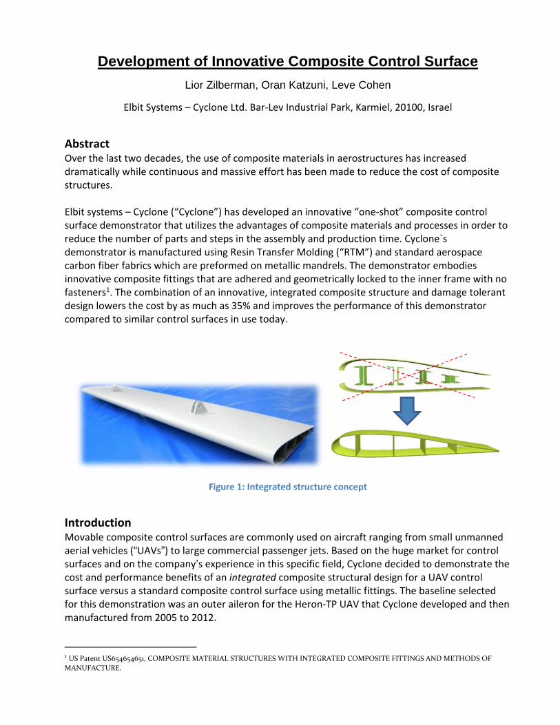
Figure 2: Left outer aileron that was selected as a baseline (circled)
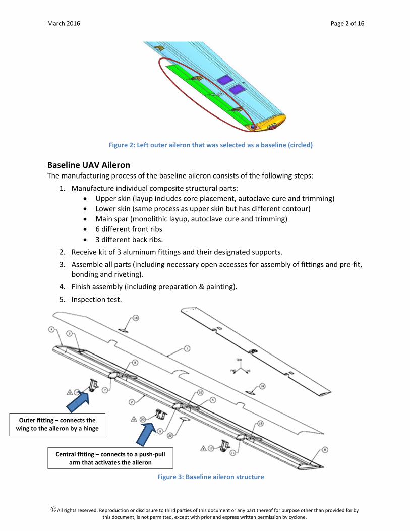
Baseline UAV Aileron The manufacturing process of the baseline aileron consists of the following steps:
1. Manufacture individual composite structural parts:
Upper skin (layup includes core placement, autoclave cure and trimming)
Lower skin (same process as upper skin but has different contour)
Main spar (monolithic layup, autoclave cure and trimming)
6 different front ribs
3 different back ribs.
2. Receive kit of 3 aluminum fittings and their designated supports.
3. Assemble all parts (including necessary open accesses for assembly of fittings and pre‐fit, bonding and riveting).
4. Finish assembly (including preparation & painting).
5. Inspection test.
Figure 3: Baseline aileron structure
Outer fitting – connects the wing to the aileron by a hinge
Central fitting – connects to a push‐pull arm that activates the aileron
March 2016 Page 3 of 16
All rights reserved. Reproduction or disclosure to third parties of this document or any part thereof for purpose other than provided for by
this document, is not permitted, except with prior and express written permission by cyclone.
Figure 5: Fittings assembly for baseline aileron using a variety of supports
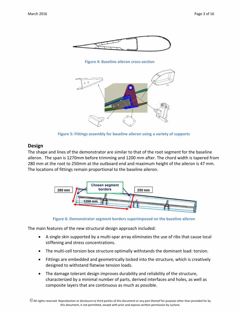
Design The shape and lines of the demonstrator are similar to that of the root segment for the baseline aileron. The span is 1270mm before trimming and 1200 mm after. The chord width is tapered from 280 mm at the root to 250mm at the outboard end and maximum height of the aileron is 47 mm. The locations of fittings remain proportional to the baseline aileron.
Figure 6: Demonstrator segment borders superimposed on the baseline aileron
The main features of the new structural design approach included:
A single skin supported by a multi‐spar array eliminates the use of ribs that cause local stiffening and stress concentrations.
The multi‐cell torsion box structure optimally withstands the dominant load: torsion.
Fittings are embedded and geometrically locked into the structure, which is creatively designed to withstand flatwise tension loads.
The damage tolerant design improves durability and reliability of the structure, characterized by a minimal number of parts, derived interfaces and holes, as well as composite layers that are continuous as much as possible.
Figure 4: Baseline aileron cross‐section

March 2016 Page 4 of 16
All rights reserved. Reproduction or disclosure to third parties of this document or any part thereof for purpose other than provided for by
this document, is not permitted, except with prior and express written permission by cyclone.
Figure 7: Demonstrator structure
Innovations Aimed to reduce cost, improve performance and facilitate aircraft certification, these
A complete structure manufactured with minimum production steps. Only pre‐cured composite fittings and adhesion of standard metallic bushings are required as associated parts and processes to form the “one‐shot” demonstrator structure. Advanced RTM technology is used to achieve a high‐quality, integrated structure that is de‐molded near net shape. The demonstrator structure contains a skin (surface 302 in Figure 8) that is wrapped on an internal built‐in frame comprising three spars (surfaces 304, 306, 308 in Figure 8). In the selected technology, RTM, liquid resin is injected at high pressure into a closed mold which contains the demonstrator preform made from dry fabric layers. Based on its experience, Cyclone characterized the RTM technology as capable of high repeatability and cost reduction compared to classic prepreg processing.
Figure 8: Demonstrator`s integrated structure
An all‐composite structure that uses a minimal number of standard materials. The demonstrator structure does not contain any core materials; therefore, their cost and the cost of associated processes for preparing them to be used in the structure are saved.
March 2016 Page 5 of 16
All rights reserved. Reproduction or disclosure to third parties of this document or any part thereof for purpose other than provided for by
this document, is not permitted, except with prior and express written permission by cyclone.
A fastener‐free structure (i.e., no rivets, screws, stitching or other fastening). This target, which replaces the common concepts of mechanical joining and metallic fittings that are used in regular aircraft control surfaces, is achieved by using pre‐cured composite fittings with patented geometry. These fittings are:
Embedded between the dry preform layers.
Secured to the structure by geometrical locking.
Co‐bonded to the structure with the injected resin that impregnates the preform. This patented design ensures that the loads will be transferred directly from the wing hinges/rods through the fittings to the structure's spars, while the geometrical locking ensures that bonding is not the only or primary load path, as required per airworthiness regulations.
The advantages of this design concept include:
High aerodynamic efficiency, achieved by the smooth contour of the skin due to no use of external parts, i.e. rivets or fitting supports.
No assembly of structural parts is required.
No extra weight from fasteners, fitting supports and filling compounds.
Thermal expansion compatibility of the all‐composite structural materials.
No fatigue concern due to use of metal components.
No stress concentrations due to holes that would be required for riveting metallic components.
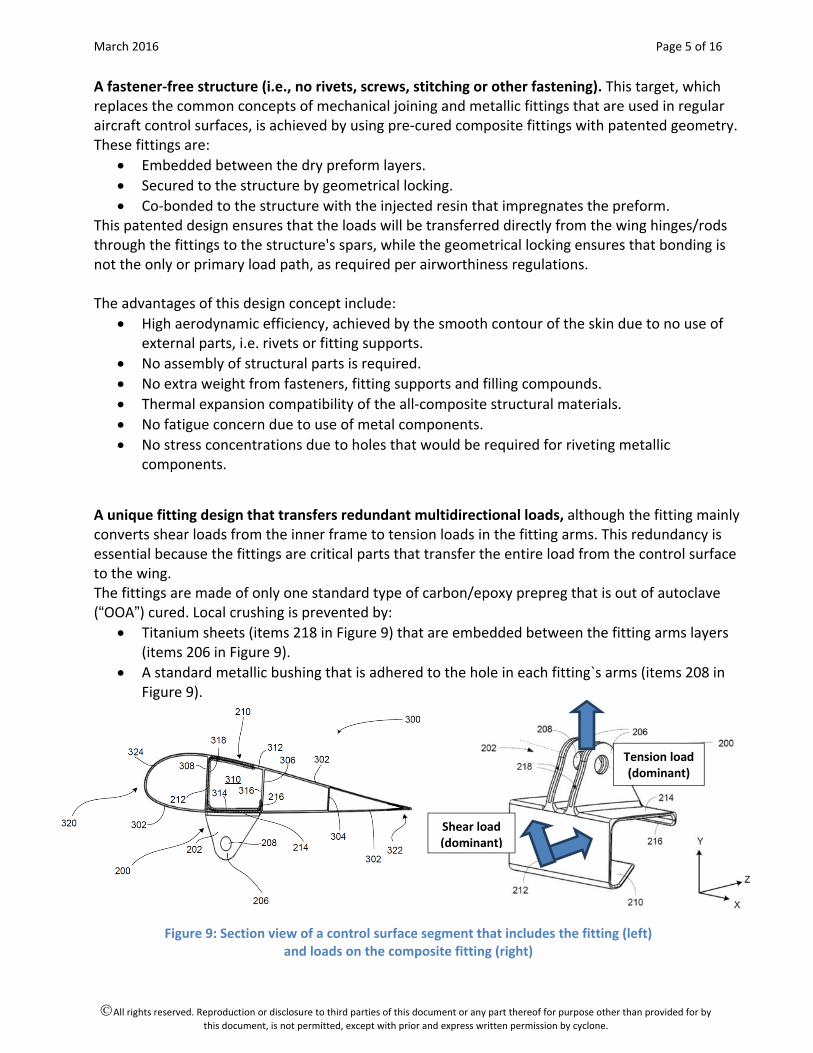
A unique fitting design that transfers redundant multidirectional loads, although the fitting mainly converts shear loads from the inner frame to tension loads in the fitting arms. This redundancy is essential because the fittings are critical parts that transfer the entire load from the control surface to the wing. The fittings are made of only one standard type of carbon/epoxy prepreg that is out of autoclave (“OOA”) cured. Local crushing is prevented by:
Titanium sheets (items 218 in Figure 9) that are embedded between the fitting arms layers (items 206 in Figure 9).
A standard metallic bushing that is adhered to the hole in each fitting`s arms (items 208 in Figure 9).
Figure 9: Section view of a control surface segment that includes the fitting (left) and loads on the composite fitting (right)
Shear load (dominant)
Tension load (dominant)
March 2016 Page 6 of 16
All rights reserved. Reproduction or disclosure to third parties of this document or any part thereof for purpose other than provided for by
this document, is not permitted, except with prior and express written permission by cyclone.
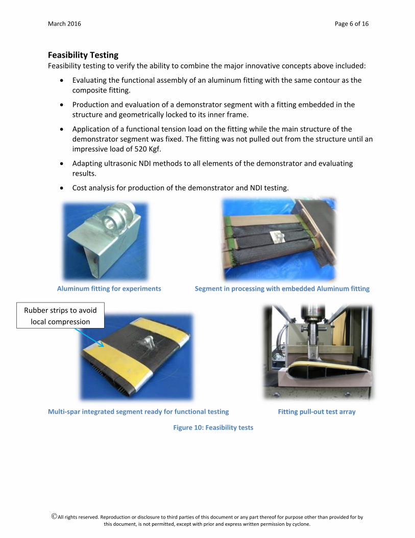
Feasibility Testing Feasibility testing to verify the ability to combine the major innovative concepts above included:
Evaluating the functional assembly of an aluminum fitting with the same contour as the composite fitting.
Production and evaluation of a demonstrator segment with a fitting embedded in the structure and geometrically locked to its inner frame.
Application of a functional tension load on the fitting while the main structure of the demonstrator segment was fixed. The fitting was not pulled out from the structure until an impressive load of 520 Kgf.
Adapting ultrasonic NDI methods to all elements of the demonstrator and evaluating results.
Cost analysis for production of the demonstrator and NDI testing.
Aluminum fitting for experiments Segment in processing with embedded Aluminum fitting
Multi‐spar integrated segment ready for functional testing Fitting pull‐out test array
Figure 10: Feasibility tests
Rubber strips to avoid
local compression
March 2016 Page 7 of 16
All rights reserved. Reproduction or disclosure to third parties of this document or any part thereof for purpose other than provided for by
this document, is not permitted, except with prior and express written permission by cyclone.
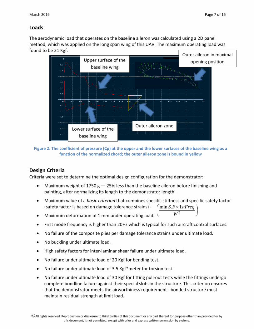
Loads
The aerodynamic load that operates on the baseline aileron was calculated using a 2D panel method, which was applied on the long span wing of this UAV. The maximum operating load was found to be 21 Kgf.
Figure 2: The coefficient of pressure (Cp) at the upper and the lower surfaces of the baseline wing as a function of the normalized chord; the outer aileron zone is bound in yellow
Design Criteria Criteria were set to determine the optimal design configuration for the demonstrator:
Maximum weight of 1750 g — 25% less than the baseline aileron before finishing and painting, after normalizing its length to the demonstrator length.
Maximum value of a basic criterion that combines specific stiffness and specific safety factor (safety factor is based on damage tolerance strains) ‐ .
Maximum deformation of 1 mm under operating load.
First mode frequency is higher than 20Hz which is typical for such aircraft control surfaces.
No failure of the composite plies per damage tolerance strains under ultimate load.
No buckling under ultimate load.
High safety factors for inter‐laminar shear failure under ultimate load.
No failure under ultimate load of 20 Kgf for bending test.
No failure under ultimate load of 3.5 Kgf*meter for torsion test.
No failure under ultimate load of 30 Kgf for fitting pull‐out tests while the fittings undergo complete bondline failure against their special slots in the structure. This criterion ensures that the demonstrator meets the airworthiness requirement ‐ bonded structure must maintain residual strength at limit load.
Outer aileron zoneLower surface of the
baseline wing
Upper surface of the
baseline wing
Outer aileron in maximal
opening position
2
1.min
W
stFreqFS
March 2016 Page 8 of 16
All rights reserved. Reproduction or disclosure to third parties of this document or any part thereof for purpose other than provided for by
this document, is not permitted, except with prior and express written permission by cyclone.
Low cost and short lead time to demonstrate operational benefits over the baseline aileron.
List of criteria to demonstrate quality including: Dimensional repeatability, weight repeatability, repeatable fiber volume above 50% and repeatable no porosity.
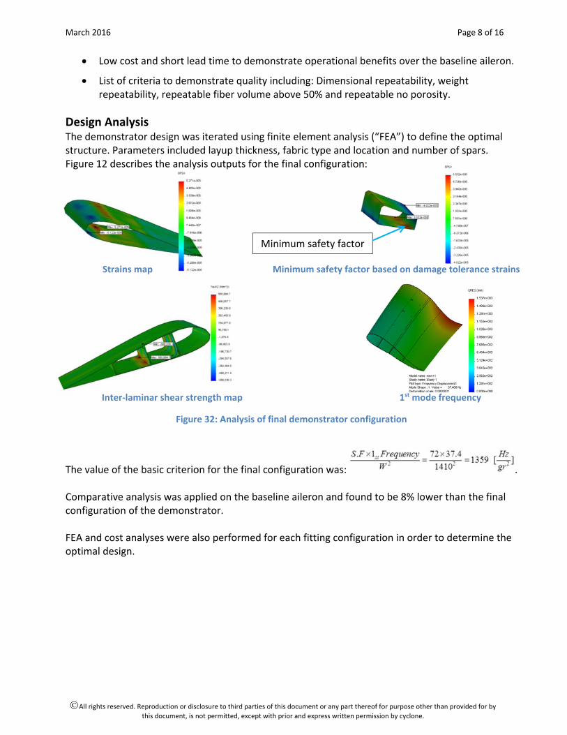
Design Analysis The demonstrator design was iterated using finite element analysis (“FEA”) to define the optimal structure. Parameters included layup thickness, fabric type and location and number of spars. Figure 12 describes the analysis outputs for the final configuration:
Strains map Minimum safety factor based on damage tolerance strains
Inter‐laminar shear strength map 1st mode frequency
Figure 32: Analysis of final demonstrator configuration
The value of the basic criterion for the final configuration was: . Comparative analysis was applied on the baseline aileron and found to be 8% lower than the final configuration of the demonstrator. FEA and cost analyses were also performed for each fitting configuration in order to determine the optimal design.
Minimum safety factor

March 2016 Page 9 of 16
All rights reserved. Reproduction or disclosure to third parties of this document or any part thereof for purpose other than provided for by
this document, is not permitted, except with prior and express written permission by cyclone.
Manufacturing Technology Demonstrator production comprised manufacturing the pre‐cured composite fittings, placing these and the dry preforms into the tooling and RTM. 1. Composite fittings manufacturing:
Layup prepreg on mold and position titanium sheets within fitting arms;
Oven cure after closing the mold;
De‐mold;
Trim edges; Ultrasonic testing.
Trimmed composite fittings OOA processing of composite fitting in mold
Figure 13: Composite fittings manufacturing
2. “One shot” RTM of the demonstrator aileron:
Preform dry fabrics on designated mandrels;
Embed pre‐cured fittings within the preform;
Place complete preform in mold + closing the mold;
Inject resin;
Cure;
De‐mold;
Post‐cure;
Trim edges;
Perform ultrasonic testing on final structure;
Assemble standard metallic bushings.
Figure 44: Demonstrator after edge trimming
March 2016 Page 10 of 16
All rights reserved. Reproduction or disclosure to third parties of this document or any part thereof for purpose other than provided for by
this document, is not permitted, except with prior and express written permission by cyclone.
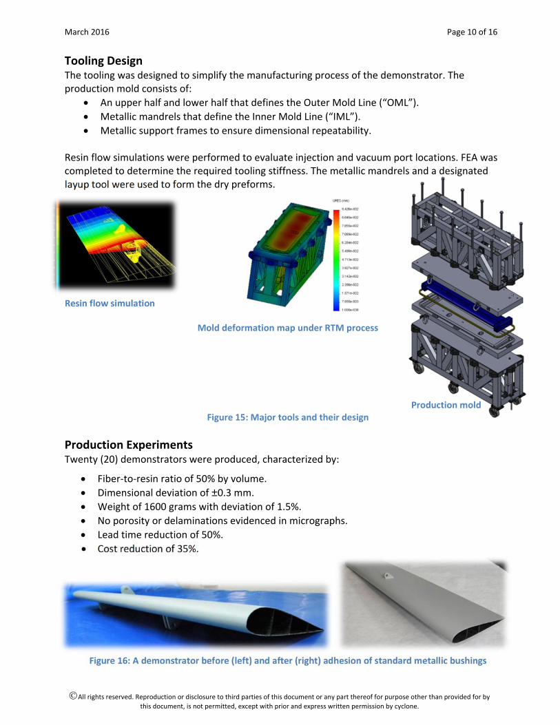
Tooling Design The tooling was designed to simplify the manufacturing process of the demonstrator. The production mold consists of:
An upper half and lower half that defines the Outer Mold Line (“OML”).
Metallic mandrels that define the Inner Mold Line (“IML”).
Metallic support frames to ensure dimensional repeatability. Resin flow simulations were performed to evaluate injection and vacuum port locations. FEA was completed to determine the required tooling stiffness. The metallic mandrels and a designated layup tool were used to form the dry preforms.
Resin flow simulation
Mold deformation map under RTM process
Production mold Figure 15: Major tools and their design
Production Experiments Twenty (20) demonstrators were produced, characterized by:
Fiber‐to‐resin ratio of 50% by volume.
Dimensional deviation of ±0.3 mm.
Weight of 1600 grams with deviation of 1.5%.
No porosity or delaminations evidenced in micrographs.
Lead time reduction of 50%.
Cost reduction of 35%.
Figure 16: A demonstrator before (left) and after (right) adhesion of standard metallic bushings
March 2016 Page 11 of 16
All rights reserved. Reproduction or disclosure to third parties of this document or any part thereof for purpose other than provided for by
this document, is not permitted, except with prior and express written permission by cyclone.
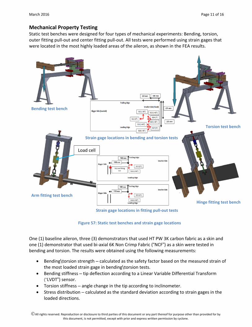
Mechanical Property Testing Static test benches were designed for four types of mechanical experiments: Bending, torsion, outer fitting pull‐out and center fitting pull‐out. All tests were performed using strain gages that were located in the most highly loaded areas of the aileron, as shown in the FEA results.
Bending test bench
Torsion test bench
Arm fitting test bench
Hinge fitting test bench
Figure 57: Static test benches and strain gage locations
One (1) baseline aileron, three (3) demonstrators that used HT PW 3K carbon fabric as a skin and one (1) demonstrator that used bi‐axial 6K Non Crimp Fabric (“NCF”) as a skin were tested in bending and torsion. The results were obtained using the following measurements:
Bending\torsion strength – calculated as the safety factor based on the measured strain of the most loaded strain gage in bending\torsion tests.
Bending stiffness – tip deflection according to a Linear Variable Differential Transform (“LVDT”) sensor.
Torsion stiffness – angle change in the tip according to inclinometer.
Stress distribution – calculated as the standard deviation according to strain gages in the loaded directions.
Load cell
Strain gage locations in bending and torsion tests
Strain gage locations in fitting pull‐out tests
March 2016 Page 12 of 16
All rights reserved. Reproduction or disclosure to third parties of this document or any part thereof for purpose other than provided for by
this document, is not permitted, except with prior and express written permission by cyclone.
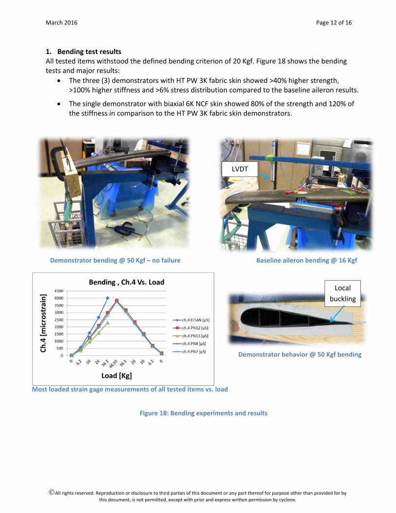
1. Bending test results All tested items withstood the defined bending criterion of 20 Kgf. Figure 18 shows the bending tests and major results:
The three (3) demonstrators with HT PW 3K fabric skin showed >40% higher strength, >100% higher stiffness and >6% stress distribution compared to the baseline aileron results.
The single demonstrator with biaxial 6K NCF skin showed 80% of the strength and 120% of the stiffness in comparison to the HT PW 3K fabric skin demonstrators.
Demonstrator bending @ 50 Kgf – no failure Baseline aileron bending @ 16 Kgf
Demonstrator behavior @ 50 Kgf bending Most loaded strain gage measurements of all tested items vs. load
Figure 18: Bending experiments and results
LVDT
Local
buckling
March 2016 Page 13 of 16
All rights reserved. Reproduction or disclosure to third parties of this document or any part thereof for purpose other than provided for by
this document, is not permitted, except with prior and express written permission by cyclone.
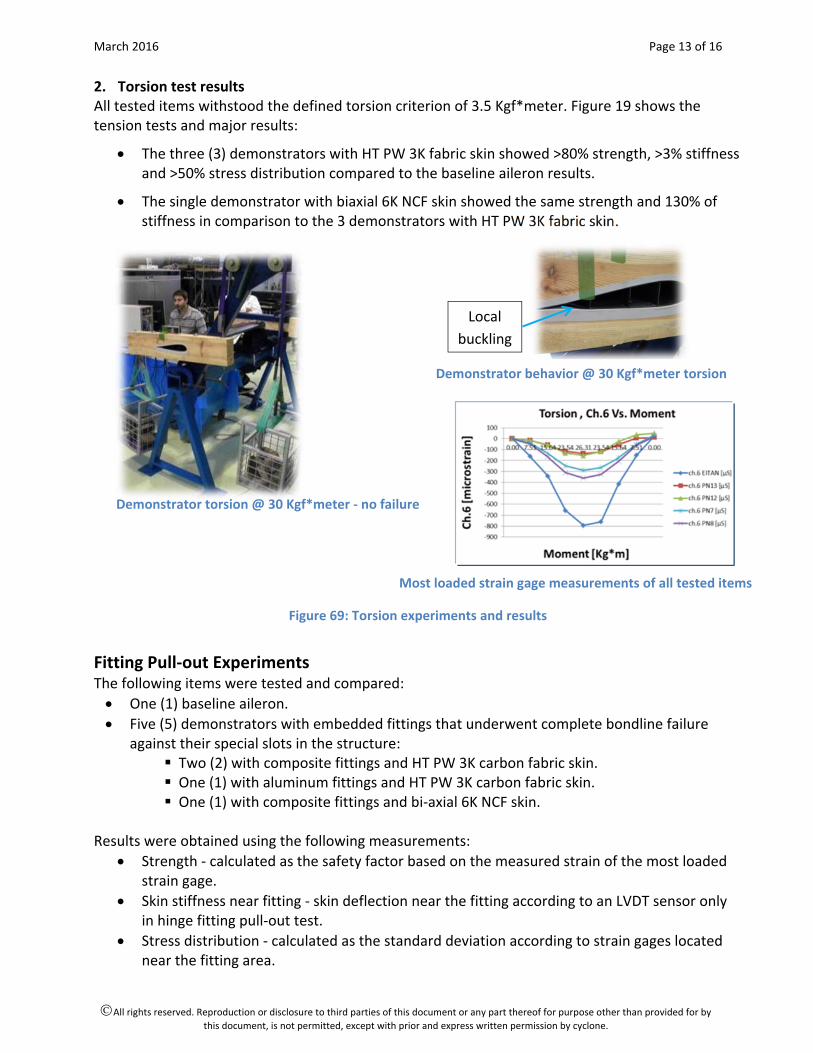
2. Torsion test results All tested items withstood the defined torsion criterion of 3.5 Kgf*meter. Figure 19 shows the tension tests and major results:
The three (3) demonstrators with HT PW 3K fabric skin showed >80% strength, >3% stiffness and >50% stress distribution compared to the baseline aileron results.
The single demonstrator with biaxial 6K NCF skin showed the same strength and 130% of stiffness in comparison to the 3 demonstrators with HT PW 3K fabric skin.
Demonstrator torsion @ 30 Kgf*meter ‐ no failure
Figure 69: Torsion experiments and results
Fitting Pull‐out Experiments The following items were tested and compared:
One (1) baseline aileron.
Five (5) demonstrators with embedded fittings that underwent complete bondline failure against their special slots in the structure:
Two (2) with composite fittings and HT PW 3K carbon fabric skin. One (1) with aluminum fittings and HT PW 3K carbon fabric skin. One (1) with composite fittings and bi‐axial 6K NCF skin.
Results were obtained using the following measurements:
Strength ‐ calculated as the safety factor based on the measured strain of the most loaded strain gage.
Skin stiffness near fitting ‐ skin deflection near the fitting according to an LVDT sensor only in hinge fitting pull‐out test.
Stress distribution ‐ calculated as the standard deviation according to strain gages located near the fitting area.
Local
buckling
Demonstrator behavior @ 30 Kgf*meter torsion
Most loaded strain gage measurements of all tested items
March 2016 Page 14 of 16
All rights reserved. Reproduction or disclosure to third parties of this document or any part thereof for purpose other than provided for by
this document, is not permitted, except with prior and express written permission by cyclone.
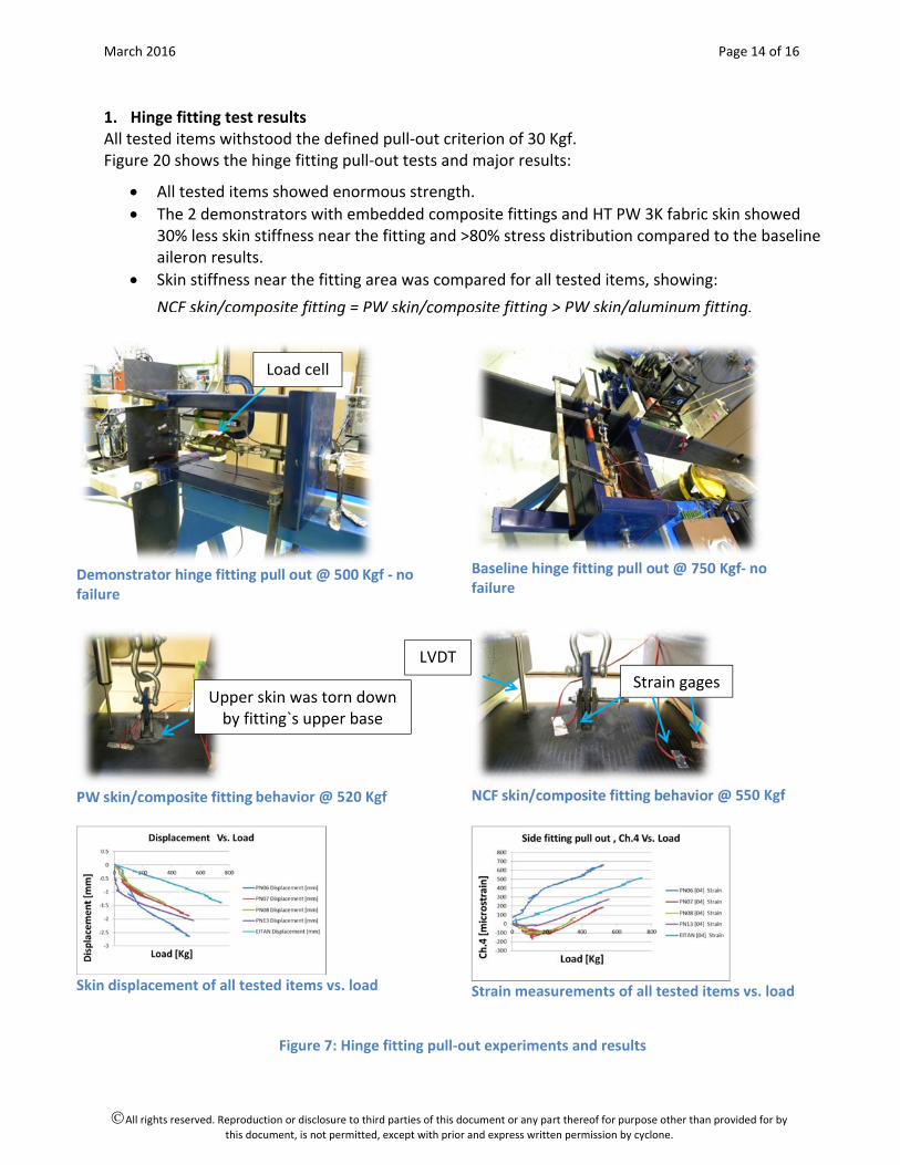
1. Hinge fitting test results All tested items withstood the defined pull‐out criterion of 30 Kgf. Figure 20 shows the hinge fitting pull‐out tests and major results:
All tested items showed enormous strength.
The 2 demonstrators with embedded composite fittings and HT PW 3K fabric skin showed 30% less skin stiffness near the fitting and >80% stress distribution compared to the baseline aileron results.
Skin stiffness near the fitting area was compared for all tested items, showing:
NCF skin/composite fitting = PW skin/composite fitting > PW skin/aluminum fitting.
Demonstrator hinge fitting pull out @ 500 Kgf ‐ no failure
Baseline hinge fitting pull out @ 750 Kgf‐ no failure
PW skin/composite fitting behavior @ 520 Kgf
NCF skin/composite fitting behavior @ 550 Kgf
Skin displacement of all tested items vs. load
Strain measurements of all tested items vs. load
Figure 7: Hinge fitting pull‐out experiments and results
Load cell
LVDT
Strain gages Upper skin was torn down by fitting`s upper base

March 2016 Page 15 of 16
All rights reserved. Reproduction or disclosure to third parties of this document or any part thereof for purpose other than provided for by
this document, is not permitted, except with prior and express written permission by cyclone.
2. Rod fitting test results All tested items withstood the defined pull‐out criterion of 30 Kgf. Figure 21 shows the rod fitting pull‐out tests and major results:
All tested items showed enormous strength.
The 2 demonstrators with embedded composite fittings and HT PW 3K fabric skin showed 50% less skin stiffness near fitting and >10% stress distribution compared to the baseline aileron results.
Skin stiffness near the fitting area of the demonstrator with biaxial 6K NCF skin/composite fitting was 85% of that for the 2 demonstrators with HT PW 3K fabric skin/composite fitting.
Demonstrator composite rod fitting pull‐out @ 410 Kgf – no failure
Demonstrator aluminum rod fitting pull‐out @ 350 Kgf – failure
Baseline Rod fitting pull out @ 830 Kgf – no failure
Strain measurements of all tested items vs. load
Figure 81: Rod fitting pull‐out experiments and results
March 2016 Page 16 of 16
All rights reserved. Reproduction or disclosure to third parties of this document or any part thereof for purpose other than provided for by
this document, is not permitted, except with prior and express written permission by cyclone.
3. Fittings performance Three (3) types of fittings were evaluated in the above tests. One strain gage was adhered to each of the fitting arms for all tested items to determine which fitting type is more appropriate for this control surface application. The specific stiffness for all 3 types was calculated and compared, showing:
The weight of the composite fitting = 65% of aluminum fitting = 35% of baseline fitting
The stiffness of the composite fitting = 200% of Aluminum fitting = 50% of baseline fitting
The specific stiffness of the composite fitting = 308% of aluminum fitting = 142% of baseline fitting.
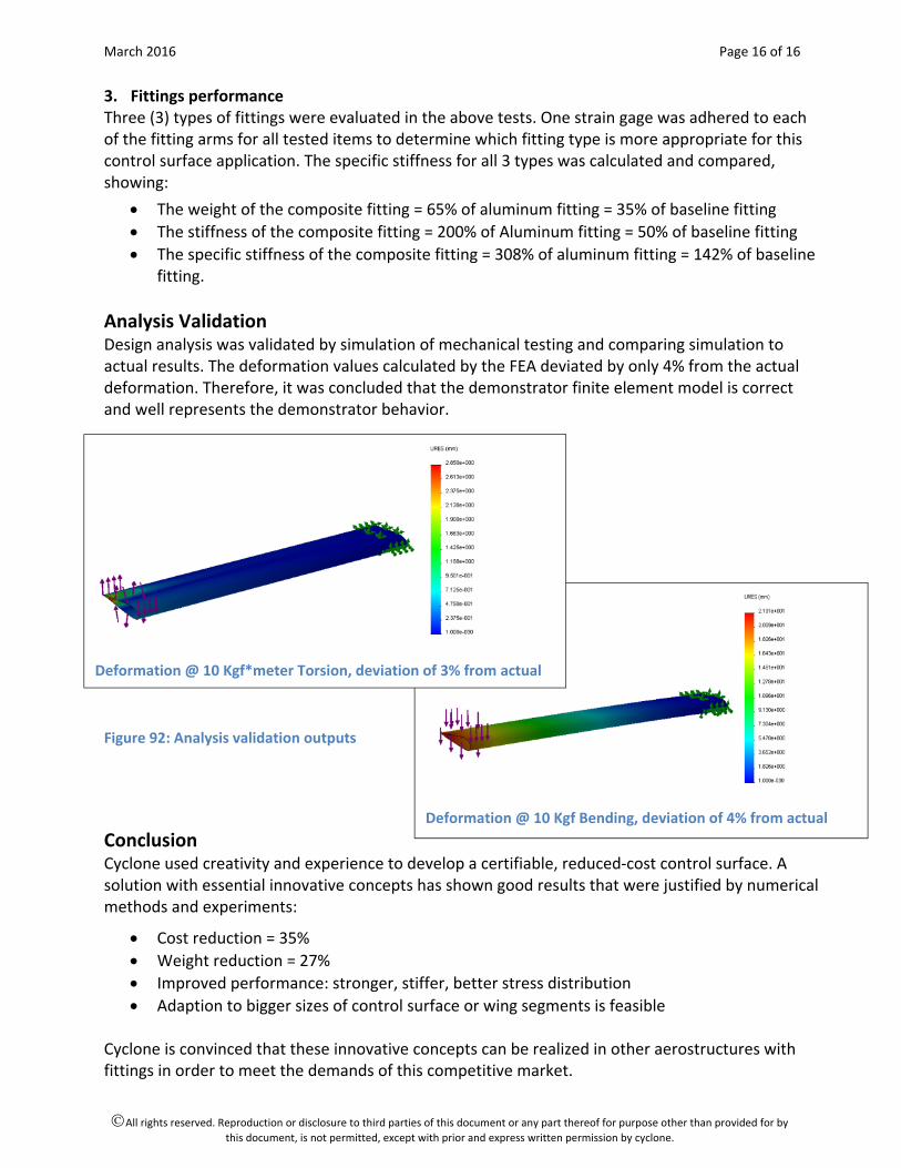
Analysis Validation Design analysis was validated by simulation of mechanical testing and comparing simulation to actual results. The deformation values calculated by the FEA deviated by only 4% from the actual deformation. Therefore, it was concluded that the demonstrator finite element model is correct and well represents the demonstrator behavior.
Figure 92: Analysis validation outputs
Conclusion Cyclone used creativity and experience to develop a certifiable, reduced‐cost control surface. A solution with essential innovative concepts has shown good results that were justified by numerical methods and experiments:
Cost reduction = 35%
Weight reduction = 27%
Improved performance: stronger, stiffer, better stress distribution
Adaption to bigger sizes of control surface or wing segments is feasible Cyclone is convinced that these innovative concepts can be realized in other aerostructures with fittings in order to meet the demands of this competitive market.
Deformation @ 10 Kgf Bending, deviation of 4% from actual
Deformation @ 10 Kgf*meter Torsion, deviation of 3% from actual