Embed Size (px)
Citation preview

Scholars' Mine
Doctoral Dissertations Student Theses and Dissertations
Fall 2015
Development of ionic liquid multi-mode spacecraftmicropropulsion systemsSteven Paul Berg
Follow this and additional works at: http://scholarsmine.mst.edu/doctoral_dissertations
Part of the Aerospace Engineering CommonsDepartment: Mechanical and Aerospace Engineering
This Dissertation - Open Access is brought to you for free and open access by Scholars' Mine. It has been accepted for inclusion in DoctoralDissertations by an authorized administrator of Scholars' Mine. This work is protected by U. S. Copyright Law. Unauthorized use includingreproduction for redistribution requires the permission of the copyright holder. For more information, please contact [email protected].
Recommended CitationBerg, Steven Paul, "Development of ionic liquid multi-mode spacecraft micropropulsion systems" (2015). Doctoral Dissertations. 2643.http://scholarsmine.mst.edu/doctoral_dissertations/2643
xiv
DEVELOPMENT OF IONIC LIQUID MULTI-MODE
SPACECRAFT MICROPROPULSION SYSTEMS
by
STEVEN PAUL BERG
A Dissertation
Presented to the Faculty of the Graduate School of the
MISSOURI UNIVERSITY OF SCIENCE AND TECHNOLOGY
In Partial Fulfillment of the Requirements for the Degree
DOCTOR OF PHILOSOPHY IN AEROSPACE ENGINEERING
2015
Approved by
Dr. Joshua Rovey, Advisor
Dr. Umit Koylu
Dr. Henry Pernicka
Dr. Benjamin Prince
Dr. David Riggins

iv
2015
Steven Paul Berg
All Rights Reserved
iii
PUBLICATION DISSERTATION OPTION
This dissertation consists of the following articles that have been submitted for
publication or are being held for submission pending patent applications:
Pages 7-56 have been submitted to the AIAA Journal of Propulsion and Power.
Submitted 5/15/2011, revision submitted 9/20/2012, accepted 9/12/2012, published
2/13/2013.
Pages 57-87 will be submitted to the AIAA Journal of Spacecraft and Rockets. In
preparation.
Pages 88-107 will be submitted to the AIAA Journal of Propulsion and Power. In
preparation.
Pages 108-133 will be submitted to the AIAA Journal of Propulsion and Power.
In preparation.
iv
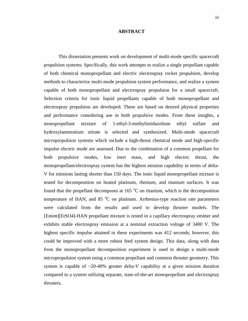
ABSTRACT
This dissertation presents work on development of multi-mode specific spacecraft
propulsion systems. Specifically, this work attempts to realize a single propellant capable
of both chemical monopropellant and electric electrospray rocket propulsion, develop
methods to characterize multi-mode propulsion system performance, and realize a system
capable of both monopropellant and electrospray propulsion for a small spacecraft.
Selection criteria for ionic liquid propellants capable of both monopropellant and
electrospray propulsion are developed. These are based on desired physical properties
and performance considering use in both propulsive modes. From these insights, a
monopropellant mixture of 1-ethyl-3-methylimidazolium ethyl sulfate and
hydroxylammonium nitrate is selected and synthesized. Multi-mode spacecraft
micropropulsion systems which include a high-thrust chemical mode and high-specific
impulse electric mode are assessed. Due to the combination of a common propellant for
both propulsive modes, low inert mass, and high electric thrust, the
monopropellant/electrospray system has the highest mission capability in terms of delta-
V for missions lasting shorter than 150 days. The ionic liquid monopropellant mixture is
tested for decomposition on heated platinum, rhenium, and titanium surfaces. It was
found that the propellant decomposes at 165 oC on titanium, which is the decomposition
temperature of HAN, and 85 oC on platinum. Arrhenius-type reaction rate parameters
were calculated from the results and used to develop thruster models. The
[Emim][EtSO4]-HAN propellant mixture is tested in a capillary electrospray emitter and
exhibits stable electrospray emission at a nominal extraction voltage of 3400 V. The
highest specific impulse attained in these experiments was 412 seconds; however, this
could be improved with a more robust feed system design. This data, along with data
from the monopropellant decomposition experiment is used to design a multi-mode
micropropulsion system using a common propellant and common thruster geometry. This
system is capable of ~20-40% greater delta-V capability at a given mission duration
compared to a system utilizing separate, state-of-the-art monopropellant and electrospray
thrusters.

v
ACKNOWLEDGMENTS
First and foremost, I would like to thank my advisor, Dr. Joshua Rovey, for his
support, advice, motivation, and trust in my abilities over the last five years. I am also
extremely grateful that he thinks enough of me to give me a postdoctoral position to
continue this research and pursue my dream of being an entrepreneur in the space
industry.
I would like to thank my faculty committee members Drs. Umit Koylu, Henry
Pernicka, and David Riggins. Their advice on this thesis has been extremely valuable and
their instruction through classes helped develop my passion and convinced me to pursue
graduate school in the first place. I am also grateful to off campus committee member,
Dr. Ben Prince, for not only serving on my committee and providing valuable insights
and expertise in electrospray physics, but also allowing me to visit AFRL Kirtland and
conduct my electrospray work.
Over the course of my graduate education, I have had the unique opportunity to
spend summers away from Rolla (valuable in its own right) and develop my skills
through various internships. In the summer of 2012 I had the opportunity to work in the
Space Chemistry II Lab at AFRL under the guidance of Dr. Jaime Stearns and Dr. Russ
Cooper. I am grateful to them not only for the opportunity, but for teaching me how to
think scientifically as well as engineeringly (not a word, but I’m publishing it anyway
because I can). In the summers of 2013 and 2014 I had the unique opportunity to work in
the propulsion systems development team at SpaceX. Special thanks to Jon Edwards,
Mike Rossoni, and Darin Van Pelt for giving me the opportunity and providing a prime
example of how to lead an engineering team. I would also like to thank Michael Clive in
particular, who has basically taught me everything I know about valves, fittings, and
McMaster. It was truly a pleasure to work with him.
Members of the APLab are also to be thanked for providing a source of
discussion, or just a source to vent frustrations onto. To Warner Meeks and Ryan Pahl:
MEEEHHHH. To Timothy Nichols and Mark Emanuel: Mo Money Less Problems. To

vi
my undergraduate students Tim Collard, Matt Glascock, Brynne Coleman, and Alex
Mundahl: thanks for your diligent efforts even though sometimes, purposefully or not, I
asked impossible tasks of you. And yes, Matt, you’re still to be referred to as my
undergrad (or at least ex-undergrad).
I should call special attention to what is now being referred to as my ‘accidental
co-op’. Thanks to the Stage 2 team at SpaceX. It has been a pleasure working with you,
though for a shorter duration than initially planned. Special thanks to Greg Krauland for
not only understanding my decision, but for actually being excited that I am pursuing my
passions.
I would like to thank all of my friends that have made grad school somewhat
more tolerable. Thanks to Jacob Darling and the AREUS Lab gang even though the word
‘covariance’ does not appear at any point in this dissertation hereafter. Thanks to the
crew comprising the infamous late March 2013 trip out west because ‘Oh s*** that’s you
guys!?!’ Thanks to Timothy and Mark for the bi-weekly bushmaster classic. Thanks to
Alex Dunn for being Alex Dunn. I have, undoubtedly, left off many folks whose
company I have had the pleasure of encountering over these past five years. Thanks to all
for helping to blow off steam after the many frustrating days that, by definition,
comprises grad school.
As far as inanimate objects, I would like to thank, as per tradition, Kapton Tape,
but also JB Weld for their magical properties of adhesion combined with high
temperature resistance and low electrical conductivity.
Thanks to my family for their love and support over these years, even though with
the time commitment of graduate school it made it difficult to spend time with you. Even
though I hear stories about October Sky and pooping at fancy restaurants just about every
time I visit home, I am truly thankful for your love.
Finally, I would like to thank Katelyn because without your reassurance every
night over the final stages of this dissertation, I may very well have not ever finished this.
vii
TABLE OF CONTENTS
Page
PUBLICATION DISSERTATION OPTION .................................................................... iii
ABSTRACT ....................................................................................................................... iv
ACKNOWLEDGMENTS .................................................................................................. v
LIST OF ILLUSTRATIONS ............................................................................................. xi
LIST OF TABLES ........................................................................................................... xiii
NOMENCLATURE ........................................................................................................ xiv
SECTION
1. INTRODUCTION ...................................................................................................... 1
1.1. DUAL-MODE SPACECRAFT PROPULSION ................................................ 2
1.1.1. Monopropellant Propulsion ...................................................................... 3
1.1.2. Electrospray Propulsion ........................................................................... 4
1.2. IONIC LIQUIDS ................................................................................................ 5
PAPER
I. Assessment of Imidazole-Based Ionic Liquids as Dual-Mode Spacecraft Propellants . . 7
ABSTRACT ................................................................................................................... 7
NOMENCLATURE ....................................................................................................... 8
1. INTRODUCTION ...................................................................................................... 9
2. IONIC LIQUID PHYSICAL PROPERTIES ........................................................... 12
2.1. THERMOCHEMICAL PROPERTIES ............................................................ 12
2.2. ELECTROCHEMICAL PROPERTIES ........................................................... 13
2.3. PHYSICAL PROPERTIES OF IONIC LIQUIDS USED IN THIS STUDY .. 15
3. CHEMICAL PERFORMANCE ANALYSIS .......................................................... 19
3.1. MONOPROPELLANT PERFORMANCE ...................................................... 20
viii
3.2. IONIC LIQUIDS IN BINARY MIXTURES AS MONOPROPELLANTS .... 22
4. ELECTROSPRAY PERFORMANCE ANALYSIS ................................................ 26
4.1. ELECTROSPRAY SYSTEM PARAMETERS ............................................... 28
4.2. ELECTROSPRAY PERFORMANCE OF SINGLE IONIC LIQUIDS........... 29
4.3. ELECTROSPRAY PERFORMANCE OF IONIC LIQUIDS IN BINARY
MIXTURES ...................................................................................................... 33
5. DISCUSSION .......................................................................................................... 36
5.1. IMIDAZOLE-BASED IONIC LIQUIDS AS MONOPROPELLANTS.......... 36
5.2. BINARY MIXTURES OF IMIDAZOLE-BASED IONIC LIQUIDS AS
MONOPROPELLANTS .................................................................................. 37
5.3. IMIDAZOLE-BASED IONIC LIQUIDS AS ELECTROSPRAY
PROPELLANTS .............................................................................................. 38
5.4. BINARY MIXTURES OF IONIC LIQUIDS AS ELECTROSPRAY
PROPELLANTS .............................................................................................. 40
5.5. CONSIDERATIONS FOR DUAL-MODE PROPELLANT DESIGN............ 41
6. CONCLUSIONS ...................................................................................................... 45
REFERENCES ............................................................................................................. 47
II. Assessment of Muti-Mode Spacecraft Micropropulsion Systems ............................... 57
ABSTRACT ................................................................................................................. 57
NOMENCLATURE ..................................................................................................... 57
1. INTRODUCTION .................................................................................................... 59
2. MULTI-MODE PROPULSION SYSTEMS............................................................ 61
3. MULTI-MODE PROPULSION SYSTEMS ANALYSIS METHODS .................. 63
3.1. THE MULTI-MODE ROCKET EQUATION ................................................. 63
3.2. CHEMICAL THRUSTER SIZING .................................................................. 67
3.3. MULTI-MODE PROPULSION SYSTEM MASS ESTIMATION
PARAMETERS................................................................................................69
3.3.1. Propellant Tankage..................................................................................69
3.3.2. Power Processing Systems......................................................................70
ix
4. RESULTS ................................................................................................................. 71
4.1. OPTIMAL SPECIFIC IMPULSE .................................................................... 72
4.2. SYSTEM SIZING............................................................................................. 74
4.3. MULTI-MODE SYSTEM PERFORMANCE ................................................. 76
4.4. MULTI-MODE SYSTEM CAPABILITIES .................................................... 77
5. DISCUSSION .......................................................................................................... 82
6. CONCLUSIONS ...................................................................................................... 84
REFERENCES ............................................................................................................. 85
III. Decomposition of a Double Salt Ionic Liquid Monopropellant on Heated Metallic
Surfaces........................................................................................................................88
ABSTRACT ................................................................................................................. 88
NOMENCLATURE ..................................................................................................... 88
1. INTRODUCTION .................................................................................................... 89
2. EXPERIMENTAL SETUP ...................................................................................... 92
3. RESULTS ................................................................................................................. 94
4. DISCUSSION ........................................................................................................ 100
4.1. DISCUSSION OF EXPERIMENTAL RESULTS ......................................... 100
4.2. ELUCIDATION OF ARRHENIUN-TYPE REACTION RATE DATA ....... 101
5. CONCLUSIONS .................................................................................................... 103
REFERENCES ........................................................................................................... 104
IV. Electrospray of an Energetic Ionic Liquid Monopropellant for Multi-Mode
Micropropulsion Applications...................................................................................108
ABSTRACT ............................................................................................................... 108
NOMENCLATURE ................................................................................................... 108
1. INTRODUCTION .................................................................................................. 109
2. EXPERIMENTAL SETUP .................................................................................... 112
x
2.1. APPARATUS ................................................................................................. 113
2.2. PROPELLANT SYNTHESIS ........................................................................ 115
3. RESULTS ............................................................................................................... 116
3.1. FLOW RATE CALIBRATION-BUBBLE METHOD .................................. 116
3.2. ANGLE-RESOLVED CURRENT MEASUREMENTS ............................... 117
3.3. ANGLE-RESOLVED MASS FLOW MEASUREMENTS ........................... 121
4. DISCUSSION ........................................................................................................ 124
4.1. CURRENT AND MASS DISTRIBUTION ................................................... 124
4.2. PERFORMANCE ........................................................................................... 125
5. CONCLUSIONS .................................................................................................... 129
REFERENCES ........................................................................................................... 130
SECTION
2. CONCEPTUAL DESIGN OF A MULTI-MODE INTEGRATED
MONOPROPELLANT ELECTROSPRAY PROPULSION SYSTEM................134
2.1. INTRODUCTION .......................................................................................... 134
2.2. FEED SYSTEM ARCHITECHTURE ........................................................... 134
2.3. THRUSTER MODELING ............................................................................. 136
2.4. PROPULSION SYSTEM CAPABILITIES ................................................... 143
REFERENCES ........................................................................................................... 145
VITA...........................................................................................................................148
xi
LIST OF ILLUSTRATIONS
Figure Page
SECTION
1.1. Simplified Schematic of Monopropellant Thruster. .............................................. 3
1.2. Simplified Schematic of Electrospray Thruster. .................................................... 5
PAPER I
1. Electric Field on Meniscus Parameter, Eq. (2), as a Function of Temperature. ..... 18
2. Specific Impulse of Binary Mixture of Ionic Liquid with HAN Oxidizer. ............ 23
3. Combustion Temperature of Binary Mixture of Ionic Liquid with Oxidizer. ........ 24
4. Major Combustion Products of Binary Mixture of [Bmim][dca] and HAN. ......... 25
5. Density Specific Impulse of IL/HAN Binary Mixture. .......................................... 26
6. Number of Emitters as a Function of Thrust for IL Propellants for RA=0.5.. ......... 31
7. Power as a Function of Thrust for IL Propellants for RA=0.5 ................................. 33
8. Number of Emitters Required to Produce 5 mN of Thrust as a Function of
Percent HAN Oxidizer for IL Binary Mixtures.......................................................35
9. Required Power to Produce 5 mN of Thrust as a Function of Percent HAN
Oxidizer for IL Binary Mixtures............................................................................ 35
PAPER II
1. Optimum Electric Specific Impulse as a Function of. ............................................ 74
2. Multi-Mode Specific Impulse as a Function of EP Usage...................................... 77
3. Payload Mass Fraction for Reference Mission as a Function of EP Usage. ........... 78
4. Burn Time for Reference Mission as a Function of EP Usage. .............................. 79
5. Mission Trade Space for Systems Utilizing Common Propellant. ......................... 80
6. Mission Design Trade Space for Multi-mode Ionic Liquid Propulsion Systems. .. 82
PAPER III
1. Photograph of the Batch Reactor Experiment in the Lab ....................................... 93
2. Illustration of the Sample Holder Geometry. .......................................................... 93
3. HAN/[Emim][EtSO4] Monopropellant Decomposition on Platinum, Rhenium,
and Titanium Surfaces ............................................................................................ 96
4. Decomposition of HAN/[Emim][EtSO4] Monopropellant and Constituent Fuel
and Oxidizer on Platinum. ...................................................................................... 99
xii
PAPER IV
1. Multi-mode thruster operated in. .......................................................................... 112
2. Electrospray experiment near-field diagnostics. ................................................... 114
3. Plumbing and instrumentation diagram of the electrospray apparatus. ................ 114
4. Flow rate as a function of reservoir pressure obtained via the bubble method. ... 117
5. Current density profiles for. ............................................ ......................................119
6. Total emission current as a function of propellant flow rate for........................... 120
7. Mass flux profiles for emission of. ....................................................................... 122
8. Thrust and specific impulse of IL propellant in a capillary emitter extrapolated
from experimental data. ........................................................................................ 129
SECTION
2.1. Schematic of the Multi-Mode Integrated Monopropellant/Electrospray
Propulsion System. ............................................................................................ 136
2.2. Model of plug flow reactor with heat effects. .................................................... 137
2.3. Thrust as a Function of Flow Rate for the Chemical Microtube Propulsion ..... 139
2.4. Minimum Mass Flow Rate Required as a Function of Inner Diameter ............. 140
2.5. Contours of Reactor Length (mm) Required to Initiate Decomposition of
Monopropellant ................................................................................................. 141
2.6. Mass of Microtube Plus Battery Power as a Function of Length. ..................... 142
2.7. Mission Design Space for Fully Integrated System versus Common
Propellant Only System. .................................................................................... 145
xiii
LIST OF TABLES
Table Page
PAPER I
1. Physical Properties of Ionic Liquids Selected for Further Study. ........................... 16
2. Chemical Performance of Ionic Liquids. ................................................................ 21
3. Equilibrium Decomposition Products of Ionic Liquids. ......................................... 22
4. Mass Data for Ionic Liquid Propellants. ................................................................. 29
5. Specific Impulse and Thrust per Unit Power .......................................................... 30
6. Estimated Attainable Physical Properties and Performance Characteristics of
Imidazole-based Dual-Mode Propellants ............................................................... 42
PAPER II
1. Performance of Multi-Mode Propulsion Systems .................................................. 62
2. Storage Properties of Propellants. ........................................................................... 70
3. Mass and Volume of Cubesat PPUs. ...................................................................... 71
4. Mass of Propulsion System Components Excluding Tankage. .............................. 75
PAPER III
1. Thermal and Electrical Properties of Catalyst Materials Used in This Study ........ 94
2. Rate of Temperature Change Before and During Decomposition Events for
Each Catalyst Surface at Various Input Power. ..................................................... 98
3. Arrhenius Rate Equation Parameters Calculated from Experimental Data. ......... 103
PAPER IV
1. Mass flow rate integrated from QCM data compared to bubble method ............. 123
2. Current, thrust, and mass to charge ratio for cation and anion emission. ............. 126
3. Thrust, power, and specific impulse for electrospray emission. ........................... 127
SECTION
4.1.2.1. System Mass Comparison for Integrated System Versus Separate System ...... 144
Mole Numbers Calculated in Eq. (3) for Each Propellant Blend. ... Error! Bookmark not
defined.
xiv
NOMENCLATURE
CA = Concentration of reactant A, [mol/m3]
CPA = Specific heat of reactant A, [J/mol-K]
F = Thrust, [N]
FA0 = Initial molar flow rate of reactant A, [mol/s]
Fi = Molar flow rate, [mol/s]
g0 = Acceleration of gravity, [m/s2]
Hi = Enthalpy of species i, [J/mol]
I = Current, [A]
spI = Specific impulse, [s]
MWA = Molecular weight of reactant A, [g/mol]
�̇� = Mass flow rate, [g/s]
Q = Volumetric flow rate, [m3/s]
�̇� = Heat transfer rate, [W]
rA = Reaction rate of reactant A, [mol/s-m3]
T = Temperature, [K]
V = Volume, [m3]
𝑊𝑠̇ = Shaft work, [W]
X = Conversion, [mol reacted/mol initial]
ΔHRX = Heat of reaction, [J/mol]

1
1. INTRODUCTION
This thesis presents work on development of multi-mode specific spacecraft
propulsion systems. Specifically, this work attempts to realize a single propellant capable
of both chemical monopropellant and electric electrospray rocket propulsion, develop
methods to characterize multi-mode propulsion system performance, and realize a system
capable of both monopropellant and electrospray propulsion for a small spacecraft.
Previous attempts at realizing a dual-mode propulsion system have focused on utilizing
available monopropellants in some electrical propulsion mode, results of which have thus
far been mixed as the monopropellants tend to be unsuitable for use, or have very low
performance in electric propulsion devices. The approach taken in the first part of this
study is to quantify traits of the propellant necessary to achieve functionality and high
performance in both chemical and electric modes. Thus, a novel multi-mode specific
propellant can be selected, synthesized, and tested. This is not intended to develop an
‘optimal’ propellant, since as will be described given current ionic liquid knowledge that
task is not possible. Rather, selection criteria are developed such that known ionic liquids
can be selected for study.
From a propulsion system perspective, proposed multi-mode propulsion systems
analysis has left a lot to be desired. Specifically, focus has been on simply outlining
concepts with focus on individual thruster specific impulse and thrust and comparison of
multi-mode systems, which by nature rely on component integration, has been lacking.
Analysis methods for multi-mode spacecraft propulsion systems are developed in the
second portion of this dissertation with particular focus on small satellite spacecraft
systems, which are not well described by specific impulse alone due to their high inert
mass fractions.
The final three sections of this dissertation focus on chemical monopropellant and
electrospray capability of the propellant developed in Part I and application to multi-
mode propulsion system design. Monopropellant decomposition characteristics are
obtained through the use of a batch reactor, and electrospray performance is obtained
2
through a capillary type emitter experiment. Results from these experiments are then used
to design a conceptual multi-mode propulsion systems using insights from Part II.
In this thesis, four papers intended for publication are presented which describe
the methods and results of research on multi-mode spacecraft propulsion. Paper I
provides a roadmap to dual-mode propellant design by describing the physical properties
and performance that can be attained within the class of ionic liquids selected for study.
Paper II presents multi-mode micro propulsion systems analysis methods. Paper III
presents experimental work on the synthesis and catalytic decomposition of a novel
propellant selected from the results of Paper I. Evidence of catalytic decomposition
provides initial proof-of-concept for use in monopropellant systems, and represents the
first step on the development path. Paper IV describes results of the electrospray emission
of the same propellant. These papers are preceded by an introduction which describes the
motivation for pursuing the research and the basic concepts of both multi-mode
spacecraft propulsion and ionic liquids. The final section uses results from all sections to
present a conceptual design of a multi-mode spacecraft propulsion system. That section is
not intended as an optimal or final design, but rather an example of the overall
methodology and design considerations developed in the previous sections.
1.1. MULTI-MODE SPACECRAFT PROPULSION
The main benefit of a multi-mode system is increased mission flexibility through
the use of both a high-thrust chemical thruster and a high-specific impulse electric
thruster. By utilizing both thrust modes, the mission design space is much larger [1].
Missions not normally accessible by a single type of thruster are possible since both are
available. The result is the capability to launch a satellite with a flexible mission plan that
allows for changes to the mission as needs arise. Since a variety of high specific impulse
and high thrust maneuvers are available in this type of system, this may also be viewed as
a technology enabling launch of a satellite without necessarily determining its thrust
history beforehand. Research has shown that a dual mode system utilizing a single ionic
liquid propellant in a chemical bipropellant or monopropellant and electrical electrospray
mode has the potential to achieve the goal of improved spacecraft mission flexibility [2-
3
4]. Furthermore, utilizing a single ionic liquid propellant for both modes would save
system mass and volume to the point where it becomes beneficial when compared to the
performance of a system utilizing a state-of-the-art chemical and electric thruster with
separate propellants, despite the performance of the ionic liquid being less than that of
each thruster separately. While a bipropellant thruster would provide higher chemical
performance, a monopropellant thruster provides the most benefit because the utilization
of a bipropellant thruster in this type of system could inherently lead to unused mass of
oxidizer since some of the fuel is used for the electrical mode [3].
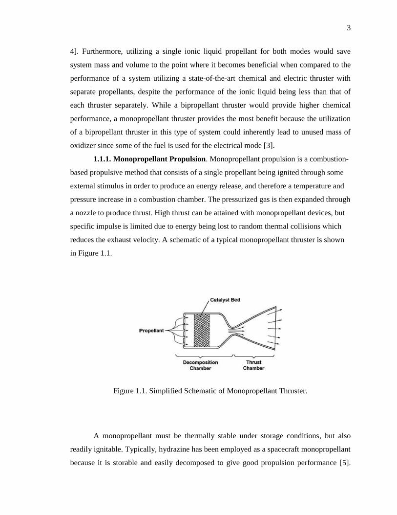
1.1.1. Monopropellant Propulsion. Monopropellant propulsion is a combustion-
based propulsive method that consists of a single propellant being ignited through some
external stimulus in order to produce an energy release, and therefore a temperature and
pressure increase in a combustion chamber. The pressurized gas is then expanded through
a nozzle to produce thrust. High thrust can be attained with monopropellant devices, but
specific impulse is limited due to energy being lost to random thermal collisions which
reduces the exhaust velocity. A schematic of a typical monopropellant thruster is shown
in Figure 1.1.
Figure 1.1. Simplified Schematic of Monopropellant Thruster.
A monopropellant must be thermally stable under storage conditions, but also
readily ignitable. Typically, hydrazine has been employed as a spacecraft monopropellant
because it is storable and easily decomposed to give good propulsion performance [5].
4
Because it is also highly toxic, recent efforts have focused on finding an alternative
“green” monopropellant. Binary or ternary mixtures including the energetic salts
hydroxyl ammonium nitrate (HAN), ammonium dinitramide (ADN), or hydrazinium
nitroformate (HNF) have been proposed as potential replacements [6-10]. These are not
true monopropellants in the traditional sense, but rather essentially premixed
bipropellants with separate oxidizer and fuel components in the mixture. Since all of
these have melting points above room temperature, they are typically stored as an
aqueous solution. A compatible fuel component such as methanol, glycerol, or
triethanolammonium nitrate (TEAN) is typically also added to provide increased
performance.
Nonspontaneously ignitable propellants, such as monopropellants, must be
decomposed by some external means before ignition can begin. Ignition is a transient
process in which reactants are rapidly transitioned to self-sustained combustion via some
external stimulus. For practical applications, the amount of energy needed to provide
ignition must be minimal, and the ignition delay time should be small [5]. The most
reliable methods of monopropellant ignition on spacecraft include thermal and catalytic
ignition, in which the monopropellant is sprayed onto a heated surface or catalyst. Other
ignition methods include spark or electrolyte ignition [11, 12]. These have been
investigated, but are less practical for spacecraft application as they require a high-
voltage power source, further increasing the weight and cost of the spacecraft. Hydrazine
monopropellant is typically ignited via decomposition by the commercially manufactured
iridium-based catalyst Shell 405. For optimum performance, the catalyst bed is typically
heated up to 200oC, but can be ‘cold-started’ with no preheat in emergency situations [5].
The Swedish ADN-based monopropellant blends require a catalyst bed preheat of 200oC.
They cannot be cold-started, which is a major limitation presently [10].
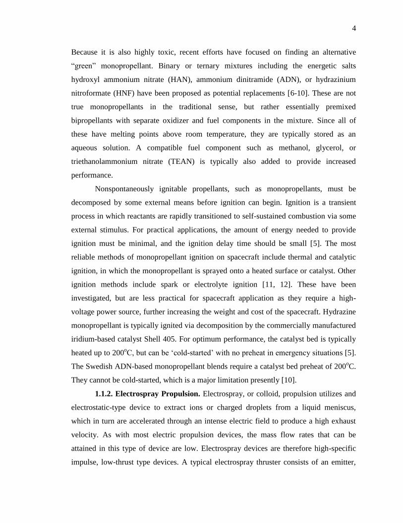
1.1.2. Electrospray Propulsion. Electrospray, or colloid, propulsion utilizes and
electrostatic-type device to extract ions or charged droplets from a liquid meniscus,
which in turn are accelerated through an intense electric field to produce a high exhaust
velocity. As with most electric propulsion devices, the mass flow rates that can be
attained in this type of device are low. Electrospray devices are therefore high-specific
impulse, low-thrust type devices. A typical electrospray thruster consists of an emitter,
5
which is essentially a needle, an extraction grid, and a power supply. The propellant may
be either externally wetted or injected through a capillary tube. A potential is applied
between the extraction grid and the needle, which causes the formation of a Taylor cone
on the surface of the propellant meniscus. If the electric field on the meniscus is
sufficiently high, ions or charged droplets are extracted and accelerated by the grid. A
typical electrospray thruster is shown in Figure 1.2.
Figure 1.2. Simplified Schematic of Electrospray Thruster.
1.2. IONIC LIQUIDS
An ionic liquid is essentially a molten, or liquid, salt. All salts obtain this state
when heated to high enough temperature; however, a special class of ionic liquids is
known as room temperature ionic liquids (RTIL’s) that remain liquid well below room
temperature. These differ from traditional aqueous ionic solutions, such as salt water, in
that a solute is not required to dissolve the ionic portion, but rather the ionic substance is
liquid in and of itself. Ionic liquids have been known since the early 20th
century;
research in the field, however, has only currently begun to increase, with the number of
papers published annually increasing from around 120 to over 2000 in just the last decade
[13]. As a result, many of the ionic liquids that have been synthesized are still being
researched, and data on their properties is not yet available. Current research has aimed at
6
synthesizing and investigating energetic ionic liquids for propellants and explosives, and
current work has highlighted the combustibility of certain ionic liquids as they approach
decomposition temperature [14, 15]. This leads to the possibility of using an ionic liquid
as a storable spacecraft propellant.
Ionic liquids have been investigated as electrospray propellants. Electrospray
liquids with relatively high vapor pressure boil off the emitter and produce an
uncontrolled, low performance emission. Ionic liquids are candidates for electrospray
propulsion due to their negligible vapor pressure and high electrical conductivity [16].
Ionic liquid emissions can range from charged droplets to a purely ionic regime (PIR)
similar to that of field emission electric propulsion with specific impulses in the range of
200-3000 seconds for current propellants [17]. The ionic liquid 1-ethyl-3-
methylimidazolium bis(trifluoromethylsulfonyl)imide ([Emim][Im]) was selected as the
propellant for the ST7 Disturbance Reduction System mission, and represents the only
application of electrospray, or colloid, thrusters to date [18]. Several other imidazole-
based ionic liquids have been suggested for research in electrospray propulsion due to
their favorable physical properties [19].
7
PAPER
I. Assessment of Imidazole-Based Ionic Liquids as Dual-Mode Spacecraft
Propellants
Steven P. Berg and Joshua L. Rovey
Missouri University of Science and Technology, Rolla, Missouri, 65409
ABSTRACT
Imidazole-based ionic liquids are investigated in terms of dual-mode chemical
monopropellant and electrospray rocket propulsion capability. A literature review of
ionic liquid physical properties is conducted to determine an initial, representative set of
ionic liquids that show favorable physical properties for both modes, followed by
numerical and analytical performance simulations. Ionic liquids [Bmim][dca],
[Bmim][NO3], and [Emim][EtSO4] meet or exceed the storability properties of hydrazine
and their electrochemical properties indicate that they may be capable of electrospray
emission in the purely ionic regime. These liquids are projected to have 13-23% reduced
monopropellant propulsion performance in comparison to hydrazine due to the prediction
of solid carbon formation in the exhaust. The use of these ionic liquids as a fuel
component in a binary monopropellant mixture with hydroxylammonium nitrate shows 1-
4% improved specific impulse over some ‘green’ monopropellants. Also, this avoids
volatility issues and reduces the number of electrospray emitters by 18-27% and power
required by 9-16%, with oxidizing ionic liquid fuels providing the greatest savings. A
fully oxygen balanced ionic liquid will exceed the state-of-the-art performance in both
modes, but will require advances in hardware technology in both modes to achieve
minimum functionality.
8
NOMENCLATURE
maxE = Maximum electric field, [V/m]
e = Fundamental charge, [C]
F = Thrust, [N]
0g = Acceleration of gravity, [m/s2]
dI = Density specific impulse, [kg-s/m3]
emitI = Current flow per emitter, [A]
iI = Output current associated with charged particle i, [A]
spI = Specific impulse, [s]
K = Electrical conductivity, [S/m]
MW = Molecular weight, [g/mol]
m = Mass of emitted species, [kg]
im = Mass of particle i, [kg]
emitm = Mass flow rate per emitter, [kg/s]
totm = Total mass flow rate, [kg/s]
emitN = Number of emitters
cP = Chamber pressure, [psi]
eP = Nozzle exit pressure, [psi]
sysP = Power of electric propulsion system, [W]
Q = Volume flow rate, [L/s]
q = Particle charge, [C]
R = Gas constant, [J/kg-K]
AR = Ion fraction
cT = Combustion temperature, [K]
mT = Melting temperature, [K]
9
accV = Electrostatic acceleration potential, [V]
eV = Exit velocity, [m/s]
, 0e NV = Exit velocity of pure ions, [m/s]
, 1e NV = Exit velocity of ions in N=1 solvated state, [m/s]
ix = Mass fraction of species i
0
fH = Heat of formation, [J/mol]
= Net accelerating potential, [V]
av = Average specific gravity
= Dielectric constant, or nozzle expansion ratio
0 = Permittivity of free space, [F/m]
= Viscosity, [cP]
sys = Efficiency of power conditioning system
= Specific heat ratio, or surface tension, [dyne/cm]
( ) = Proportionality coefficient
= Density, [g/cm3]
i = Density of species i, [g/cm3]
n = Density of mixture n, [g/cm3]
1. INTRODUCTION
In a true dual-mode spacecraft propulsion system, the same propellant is used for
both high thrust, low specific impulse (chemical propulsion) and low thrust, high specific
impulse thrusters (electric propulsion). This has many advantages, most importantly
higher mission flexibility in terms of the ability to dictate maneuvers as mission needs
arise on orbit rather than before launch. At the same time, utilizing a single propellant
provides maximum flexibility and significantly reduces system mass and volume over a
10
spacecraft utilizing separate propellants for each thrust mode. Ionic liquids have potential
to be utilized in either a chemical thruster or an electric thruster. The goal of this paper is
to examine typical ionic liquids in terms of their capability for use as propellants in a
dual-mode propulsion system. Since the list of available ionic liquids is enormous, and
most liquids are not yet well characterized, this study will also attempt to identify trends
favorable toward dual-mode propulsion in order to provide guidelines for the selection of
ionic liquids for future use in dual-mode propellant research. This paper describes and
examines requirements on the physical properties of various ionic liquids to assess their
potential for use as propellants in a potential dual-mode system. Projected chemical and
electrical propulsion performance of sample ionic liquids that have shown favorable
properties toward feasible operation in both modes is then computed and compared to the
current state-of-the-art in both chemical monopropellant and electrospray propulsion.
As stated, the main benefit of a dual-mode system is increased mission flexibility
through the use of both a high-thrust chemical thruster and a high-specific impulse
electric thruster utilizing the same fuel. By utilizing both thrust modes, the mission
design space is much larger [1]. Missions not normally accessible by a single type of
thruster are possible since both are available. Furthermore, this enables mission designers
to develop with a flexible mission plan that allows for changes to the mission as needs
arise. Since a single propellant is utilized for both modes, this may also be viewed as a
technology enabling launch of a satellite without necessarily even determining any thrust
history beforehand because both types of maneuvers are available, while still resulting in
100% propellant utilization regardless of the specific type, frequency, or order of desired
maneuvers . Research has shown that a particular dual mode system concept utilizing a
single ionic liquid propellant in a chemical monopropellant and electric electrospray
mode has the potential to achieve mission flexibility gains and mass savings over a
system utilizing separate propellants for each mode even if the common propellant
performs below state-of-the-art in either mode [2-4].
An ionic liquid is essentially a molten, or liquid, salt. All salts obtain this state
when heated to high enough temperature; however, an ionic liquid is typically defined as
attaining liquid state below 100oC. There exists a special class of ionic liquids known as
room temperature ionic liquids (RTIL’s) that remain liquid well below room temperature.
11
Ionic liquids have been known since the early 20th
century; research in the field, however,
has only currently begun to increase, with the number of papers published annually
increasing from around 120 to over 2000 in just the last decade [5]. As a result, many of
the ionic liquids that have been synthesized are still being researched, and data on their
properties is not yet available. Additionally, the number of ionic liquids theorized, but not
yet synthesized has been estimated in the millions [6] and the estimated number of
possible ionic liquids is on the order of ~1018
[7]. Current research has aimed at
synthesizing and investigating energetic ionic liquids for propellants and explosives, and
current work has highlighted the combustibility of certain ionic liquids as they approach
decomposition temperature [8, 9]. This leads to the possibility of using an ionic liquid as
a storable spacecraft monopropellant.
Hydrazine has been the monopropellant of choice for spacecraft and gas
generators because it is storable and easily decomposed to give good combustion
properties [10]. However, hydrazine is also highly toxic and recent efforts have been
aimed at replacing hydrazine with a high-performance, non-toxic monopropellant. The
energetic salts hydroxylammonium nitrate (HAN), ammonium dinitramide (ADN), and
hydrazinium nitroformate (HNF) have received attention as potential replacements [10-
14]. All of these salts have melting points above room temperature, and it is therefore
necessary to use them in an aqueous solution to create a storable liquid propellant.
Typically, these are also mixed with a compatible fuel component to provide improved
performance. The main limitation to the development of these as monopropellants has
been excessive combustion temperatures [14, 15]. Engineers in Sweden, however, have
recently flight tested an ADN-based thruster capable of handling combustion
temperatures exceeding 1900 K [14].
Electrospray is a propulsion technology in which charged liquid droplets or ions
are extracted from an emitter via an applied electric field [16]. Electrospray liquids with
relatively high vapor pressure boil off the propellant and produce an uncontrolled, low
performance emission. Ionic liquids are candidates for electrospray propulsion due to
their negligible vapor pressure and high electrical conductivity [17]. Ionic liquid
emissions can range from charged droplets to a purely ionic regime (PIR) similar to that
of field emission electric propulsion with specific impulses in the range of 200-3000
12
seconds for current propellants [16]. The ionic liquid 1-ethyl-3-methylimidazolium
bis(trifluoromethylsulfonyl)imide ([Emim][Im], or [Emim][Tf2N]) was selected as the
propellant for the ST7 Disturbance Reduction System mission, and represents the only
planned flight application of electrospray, or colloid, thrusters to date [18]. Several other
imidazole-based ionic liquids have been suggested for research in electrospray propulsion
due to their favorable physical properties [19].
The following sections analyze the potential of ionic liquids to be used as
spacecraft propellants in a dual-mode system and develops criterion for selection or
design of true dual-mode propellants. Section II identifies the physical properties required
for acceptable performance in both modes. Sample ionic liquids are then selected for
performance analysis. Section III investigates the projected chemical performance of
these ionic liquids as monopropellants. Section IV examines the projected electrospray
performance of the ionic liquid propellants. The results of the preceding sections are
discussed, and criteria for future dual-mode propellant selection and developments are
presented in Section V. Section VI presents conclusions based on the entirety of analyses.
2. IONIC LIQUID PHYSICAL PROPERTIES
Fundamental physical properties required of ionic liquids to perform as both
monopropellants and electrospray propellants in a spacecraft environment are identified.
These properties are compared to those of the current state-of-the-art propellants to
develop tools and criterion to assess the feasibility of using these and other ionic liquids
for the intended application.
2.1. THERMOCHEMICAL PROPERTIES
The fundamental thermochemical properties required to initially analyze the
ability of ionic liquids to perform as spacecraft propellants include the following: melting
temperature, density, viscosity, and heat of formation [10]. High density, low melting
13
temperature, and low viscosity are desired traits common to both propulsive modes in the
dual-mode system because they do not have a significant effect on the operation of each
thruster, but represent the storability of propellants only. A low viscosity aids in
transporting the propellant from the tank and its subsequent injection into either type of
thruster. A low melting temperature is desired so that the power required to keep the
propellant in liquid form is minimal. Monopropellant grade hydrazine has a melting
temperature of 2o C, so it is reasonable to assume that new propellants must fall near or
below this value. Density is an additional storability consideration. A high density is
desired to accommodate a large amount of propellant in a given volume on a spacecraft.
The chemical propellant must also be easily ignitable and give good combustion
properties. The heat of formation of the compound is required to estimate the equilibrium
composition, and subsequently compute the estimated chemical performance, namely
specific impulse. A high heat of formation results in a greater energy release upon
combustion, therefore a higher combustion temperature, and subsequently a higher
specific impulse for a given species and number of combustion products.
2.2. ELECTROCHEMICAL PROPERTIES
The electrochemical properties important for electrospray propulsion include both
surface tension and electrical conductivity. The highest performance in terms of specific
impulse is attained for emissions in the purely ionic regime (PIR). Emission of charged
droplets, rather than clusters of ions, greatly reduces the specific impulse and efficiency
of the emitter. [Emim][Im], for example, operates in the purely ionic regime with a
specific impulse of around 3500 seconds [20], but in the droplet regime, this drops to
lower than 200 seconds [21]. Droplet emission, however, does produce a larger amount
of thrust due to emission of heavier species, and this may be desirable in some instances,
but ultimately the most flexible ionic liquids for electrospray propulsion will attain
emission in the PIR. Liquids with sufficiently high surface tension and electrical
conductivity have been shown to be capable of operating in the PIR. This has been
shown both theoretically and experimentally [19, 22, 23], and is related to the maximum
electric field on the meniscus of the liquid on the emitter [18, 19]

14
1/2 2/3 1/6
max 0( ) ( / )E K Q (1)
Additionally, De La Mora [19, 23] has shown that the smallest flow rate that can form a
stable Taylor cone scales as γ/K, hence [19]
1/3
max ~ ( )E K (2)
Experimental results indicate that the PIR is achieved at a meniscus electric field of
roughly 1 V/nm [16]. It should be noted that Eqs. (1) and (2) do not accurately predict the
meniscus electric field for PIR emissions. Instead, because experimental results indicate a
similar trend for liquids that have attained PIR emission, Eq. (2) will be used as a
comparison tool. This relation is a measure of the ability of an ionic liquid to form a
Taylor cone with emission in the purely ionic regime, and does not necessarily translate
to thruster performance. The thrust and specific impulse for an electric propulsion system
by an individual particle are calculated as [10, 16]
2 ( / )i acc iF I V m q (3)
0(1/ ) 2 ( / )sp acc iI g V q m (4)
A high charge per mass is desired for high specific impulse, but is inversely proportional
to thrust. As a result, practical specific impulse is limited by power available, since an
excessively high specific impulse requires large amounts of power to process enough
current to produce even small amounts of thrust. Higher molecular weight propellants are
desirable due to the higher thrust produced by emission of heavier ions. Therefore, ionic
liquids with electrical conductivity and surface tension close to the current state-of-the-art
electrospray propellants that have achieved PIR operation and high molecular weight are
of greatest benefit.

15
2.3. PHYSICAL PROPERTIES OF IONIC LIQUIDS USED IN THIS STUDY
The number of ionic liquids available for study is numerous; therefore, this study
has initially been restricted to only imidazole-based ionic liquids. The main reason for
selecting imidazole-based ionic liquids is their capability as electrospray propellants,
particularly those based on the [Emim]+ cation [19]. A recent patent on this particular
type of dual-mode system lists several potential ionic liquid propellants, most of which
are imidazole-based [24]. These are used in the initial screening for chemicals of interest;
however, many ionic liquids do not have enough published physical property data to
make definite estimates of initial system feasibility. In particular, heat of formation is not
available for many of the ionic liquids considered initially. It is therefore necessary and
useful to consider trends in the physical properties of ionic liquids. This will be discussed
in further detail in a later section, but in the interest of providing examples in this study
and to discern performance trends, three ionic liquids are selected for further study based
on availability of property data: 1-butyl-3-methylimidazolium nitrate ([Bmim][NO3]), 1-
butyl-3-methylimidazolium dicyanamide [Bmim][dca], and 1-ethyl-3-methylimidazolium
ethyl sulfate ([Emim][EtSO4]). Representative physical property data for these ionic
liquids are shown in Table 1. The properties of hydrazine and [Emim][Im] are shown for
comparison of thermochemical and electrochemical properties, respectively. The density,
viscosity, electrical conductivity, and surface tension reported in the table are at a
temperature of 298 K for all liquids listed, except for the electrical conductivity of
[Bmim][NO3], where the only data point given in literature is at a temperature of 379 K.
The properties found in the literature vary slightly due to differences in experimental
technique and purity of the ionic liquid sample, but in general the results agree within less
than 1% [46-56]. The values shown in Table 1 are the most conservative values in
reference to the discussions in this paper.
16
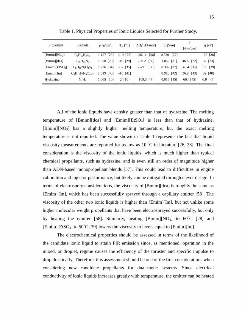
Table 1. Physical Properties of Ionic Liquids Selected for Further Study.
Propellant Formula ρ [g/cm3] Tm [oC] ΔHfo [kJ/mol] K [S/m]
γ
[dyn/cm] η [cP]
[Bmim][NO3] C8H15N3O3 1.157 [25] <10 [25] -261.4 [26] 0.820 [27]
165 [28]
[Bmim][dca] C10H15N5 1.058 [29] -10 [29] 206.2 [30] 1.052 [31] 46.6 [32] 32 [33]
[Emim][EtSO4] C8H16N2O4S1 1.236 [34] -37 [35] -579.1 [36] 0.382 [37] 45.4 [38] 100 [39]
[Emim][Im] C8H11F6N3O4S2 1.519 [40] -18 [41]
0.910 [42] 36.9 [43] 32 [40]
Hydrazine N2H4 1.005 [10] 2 [10] 109.3 [44] 0.016 [45] 66.4 [45] 0.9 [45]
All of the ionic liquids have density greater than that of hydrazine. The melting
temperature of [Bmim][dca] and [Emim][EtSO4] is less than that of hydrazine.
[Bmim][NO3] has a slightly higher melting temperature, but the exact melting
temperature is not reported. The value shown in Table 1 represents the fact that liquid
viscosity measurements are reported for as low as 10 o
C in literature [26, 28]. The final
consideration is the viscosity of the ionic liquids, which is much higher than typical
chemical propellants, such as hydrazine, and is even still an order of magnitude higher
than ADN-based monopropellant blends [57]. This could lead to difficulties in engine
calibration and injector performance, but likely can be mitigated through clever design. In
terms of electrospray considerations, the viscosity of [Bmim][dca] is roughly the same as
[Emim][Im], which has been successfully sprayed through a capillary emitter [58]. The
viscosity of the other two ionic liquids is higher than [Emim][Im], but not unlike some
higher molecular weight propellants that have been electrosprayed successfully, but only
by heating the emitter [58]. Similarly, heating [Bmim][NO3] to 60oC [28] and
[Emim][EtSO4] to 50oC [39] lowers the viscosity to levels equal to [Emim][Im].
The electrochemical properties should be assessed in terms of the likelihood of
the candidate ionic liquid to attain PIR emission since, as mentioned, operation in the
mixed, or droplet, regime causes the efficiency of the thruster and specific impulse to
drop drastically. Therefore, this assessment should be one of the first considerations when
considering new candidate propellants for dual-mode systems. Since electrical
conductivity of ionic liquids increases greatly with temperature, the emitter can be heated
17
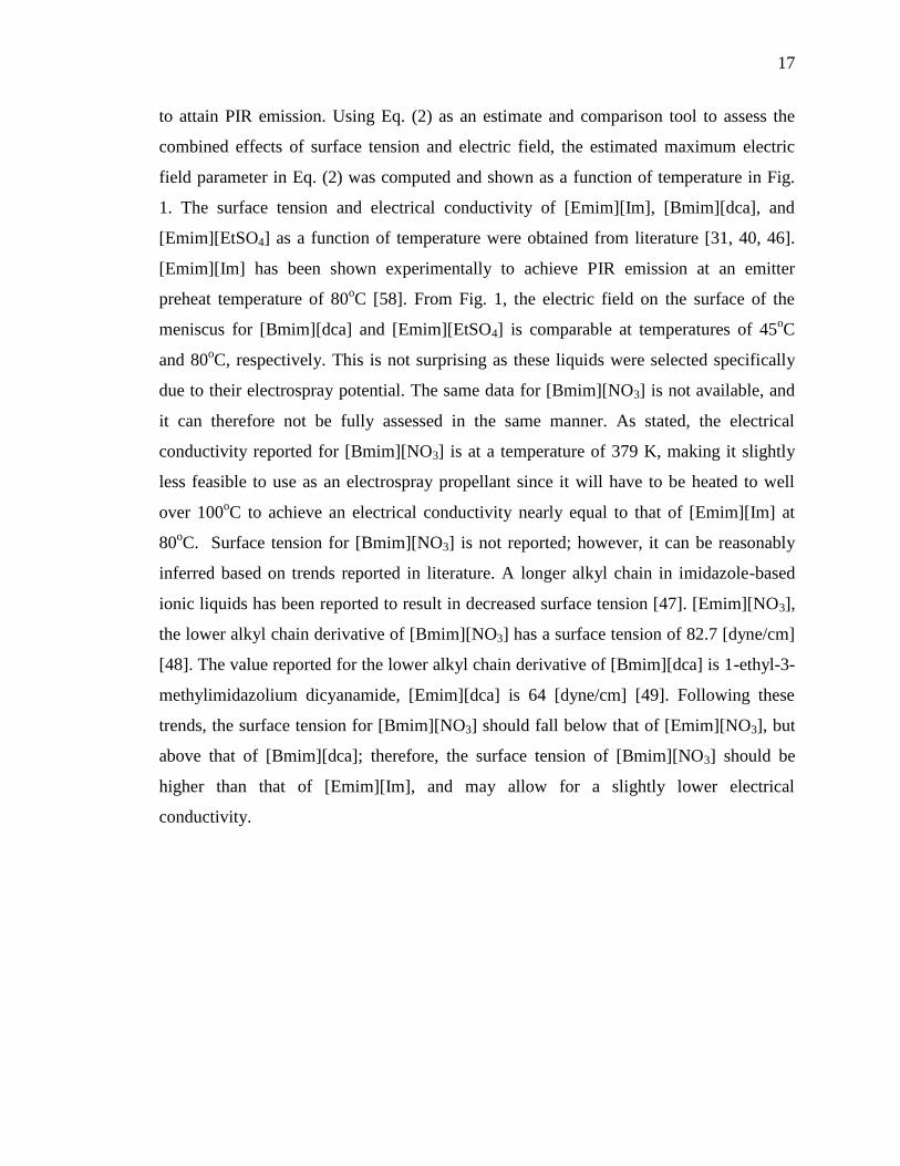
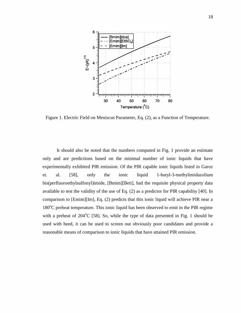
to attain PIR emission. Using Eq. (2) as an estimate and comparison tool to assess the
combined effects of surface tension and electric field, the estimated maximum electric
field parameter in Eq. (2) was computed and shown as a function of temperature in Fig.
1. The surface tension and electrical conductivity of [Emim][Im], [Bmim][dca], and
[Emim][EtSO4] as a function of temperature were obtained from literature [31, 40, 46].
[Emim][Im] has been shown experimentally to achieve PIR emission at an emitter
preheat temperature of 80oC [58]. From Fig. 1, the electric field on the surface of the
meniscus for [Bmim][dca] and [Emim][EtSO4] is comparable at temperatures of 45oC
and 80oC, respectively. This is not surprising as these liquids were selected specifically
due to their electrospray potential. The same data for [Bmim][NO3] is not available, and
it can therefore not be fully assessed in the same manner. As stated, the electrical
conductivity reported for [Bmim][NO3] is at a temperature of 379 K, making it slightly
less feasible to use as an electrospray propellant since it will have to be heated to well
over 100oC to achieve an electrical conductivity nearly equal to that of [Emim][Im] at
80oC. Surface tension for [Bmim][NO3] is not reported; however, it can be reasonably
inferred based on trends reported in literature. A longer alkyl chain in imidazole-based
ionic liquids has been reported to result in decreased surface tension [47]. [Emim][NO3],
the lower alkyl chain derivative of [Bmim][NO3] has a surface tension of 82.7 [dyne/cm]
[48]. The value reported for the lower alkyl chain derivative of [Bmim][dca] is 1-ethyl-3-
methylimidazolium dicyanamide, [Emim][dca] is 64 [dyne/cm] [49]. Following these
trends, the surface tension for [Bmim][NO3] should fall below that of [Emim][NO3], but
above that of [Bmim][dca]; therefore, the surface tension of [Bmim][NO3] should be
higher than that of [Emim][Im], and may allow for a slightly lower electrical
conductivity.
18
Figure 1. Electric Field on Meniscus Parameter, Eq. (2), as a Function of Temperature.
It should also be noted that the numbers computed in Fig. 1 provide an estimate
only and are predictions based on the minimal number of ionic liquids that have
experimentally exhibited PIR emission. Of the PIR capable ionic liquids listed in Garoz
et. al. [58], only the ionic liquid 1-butyl-3-methylimidazolium
bis(perfluoroethylsulfonyl)imide, [Bmim][Beti], had the requisite physical property data
available to test the validity of the use of Eq. (2) as a predictor for PIR capability [40]. In
comparison to [Emim][Im], Eq. (2) predicts that this ionic liquid will achieve PIR near a
180oC preheat temperature. This ionic liquid has been observed to emit in the PIR regime
with a preheat of 204oC [58]. So, while the type of data presented in Fig. 1 should be
used with heed, it can be used to screen out obviously poor candidates and provide a
reasonable means of comparison to ionic liquids that have attained PIR emission.
19
3. CHEMICAL PERFORMANCE ANALYSIS
The three aforementioned liquids are feasible candidates for both chemical and
electrical propulsion purely based on their reported physical properties. Although initially
selected mainly because of electrospray considerations, a chemical rocket performance
analysis is conducted to determine if they have potential as chemical monopropellants
with the understanding that they may perform below state-of-the-art, but have dual-mode
capability. Equilibrium combustion analysis is conducted using the NASA Chemical
Equilibrium with Applications (CEA) computer code [44]. In each case, the temperature
of the reactants is assumed to be 298 K. Where applicable, specific impulse is calculated
by assuming frozen flow at the throat [10]
( 1)
21
1
c esp
c
RT PI
MW P
(5)
1 11
11 1 11
2 1
e e
c c
P P
P P
(6)
Given a combustion pressure and nozzle expansion ratio, Eqs. (5) and (6) are then only
functions of the combustion gas temperature and products, which are given in the CEA
output. When condensed species are found to be present in the equilibrium combustion
products, a shifting equilibrium assumption through the nozzle must be applied instead to
account for the multi-phase flow. For each simulation hereafter a chamber pressure of
300 psi and nozzle expansion ratio of 50 are assumed. These represent typical values for
on-orbit engines [59]. The ambient pressure is taken as vacuum, therefore the specific
impulse computed is the absolute maximum for the given design conditions. As an
additional measure of chemical performance, the density specific impulse, is computed
simply from [10]

20
d av spI I (7)
3.1. MONOPROPELLANT PERFORMANCE
The CEA computer code is utilized to determine the expected performance of the
ionic liquids as monopropellants with the assumptions and conditions described above.
The reaction is then decomposition of the ionic liquid into gaseous products. The
computed specific impulse and density impulse values are shown in Table 2. CEA
predicts condensed carbon in the exhaust species for the ionic liquids; therefore, the
specific impulse shown in the table is for shifting equilibrium. For comparison, the
performance of ADN-based monopropellant FLP-103 (63.4% ADN, 25.4% water, 11.2%
methanol) is also computed. The specific impulse computed in this analysis for FLP-103
agrees precisely with the theoretical calculations performed by Wingborg, et.al. [57] at
the same design conditions and a frozen flow assumption, as CEA was also utilized in
that study for performance prediction. The maximum specific impulse for hydrazine is
257 sec [45] and is where the catalyst bed has been designed to allow for no ammonia to
dissociate. Typically, however, hydrazine monopropellant thrusters operate around 243
sec since the catalyst bed cannot handle the high combustion temperature [10]. None of
the ionic liquids show performance comparable to that of hydrazine, with [Bmim][NO3]
coming closest at a value of 13.2% lower specific impulse. The performance of the ionic
liquids is slightly more promising in terms of density specific impulse. [Bmim][dca], and
[Emim][EtSO4] fall 18% and 5.3%, respectively, below that of hydrazine, while
[Bmim][NO3] has a density specific impulse equal to that of hydrazine. None of the ionic
liquids compete with the theoretical density specific impulse of advanced monopropellant
FLP-103, which is predicted to be 35% higher than hydrazine.
21
Table 2. Chemical Performance of Ionic Liquids
Propellant Isp [s] Id [kg-s/m3]
[Bmim][NO3] 211 244000
[Bmim][dca] 189 200000
[Emim][EtSO4] 186 231000
FLP-103 254 (Equilibrum)
251 (Frozen)
333000
329000
Hydrazine 243 244000
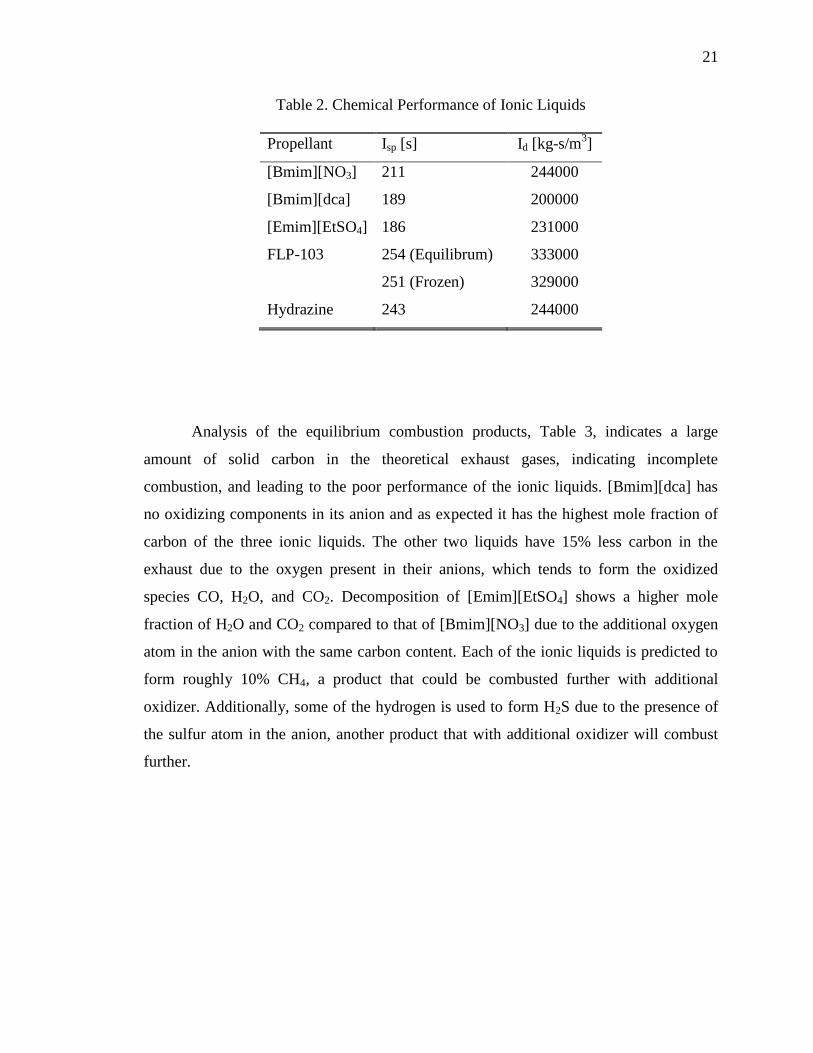
Analysis of the equilibrium combustion products, Table 3, indicates a large
amount of solid carbon in the theoretical exhaust gases, indicating incomplete
combustion, and leading to the poor performance of the ionic liquids. [Bmim][dca] has
no oxidizing components in its anion and as expected it has the highest mole fraction of
carbon of the three ionic liquids. The other two liquids have 15% less carbon in the
exhaust due to the oxygen present in their anions, which tends to form the oxidized
species CO, H2O, and CO2. Decomposition of [Emim][EtSO4] shows a higher mole
fraction of H2O and CO2 compared to that of [Bmim][NO3] due to the additional oxygen
atom in the anion with the same carbon content. Each of the ionic liquids is predicted to
form roughly 10% CH4, a product that could be combusted further with additional
oxidizer. Additionally, some of the hydrogen is used to form H2S due to the presence of
the sulfur atom in the anion, another product that with additional oxidizer will combust
further.
22
Table 3. Equilibrium Decomposition Products of Ionic Liquids
Product Species
Mole Fraction
[Bmim][NO3] [Bmim][dca] [Emim][EtSO4]
C 0.35 0.50 0.35
N2 0.10 0.15 0.07
H2 0.27 0.24 0.19
H2O 0.07 0.00 0.11
CO 0.09 0.00 0.07
CO2 0.02 0.00 0.05
CH4 0.09 0.11 0.09
H2S 0.00 0.00 0.07
3.2. IONIC LIQUIDS IN BINARY MIXTURES AS MONOPROPELLANTS
The possibility of using ionic liquids as fuel components in a binary
monopropellant mixture is considered. This may, in fact, be possible due to the ionic
liquids capability as solvents, particularly [Bmim][dca] and [Bmim][NO3], as their anions
have H-bond accepting functionality [53, 60]. Furthermore, many imidazole-based ionic
liquids tend to have solubility properties close to those of methanol and ethanol [6].
HAN, also, is noted for its solubility in water and fuels such as methanol, which led to its
initial application as a liquid gun propellant [61]. Additionally, these are the ingredients
to FLP-103, and the solubility of ADN in both water and methanol was a key to the
development of the monopropellant [12, 57]. [Bmim][dca] has been tested for
hypergolicity with HAN oxidizer, and, notably, it showed no visible signs of reactivity at
room temperature [62]. A monopropellant mixture of the ionic liquids with HAN, or
another oxidizer salt, may be created which would be thermally stable at room
temperature, and ignited thermally or catalytically.
CEA is again employed with the same conditions applied previously, and with shifting
equilibrium assumption. Specific impulse is calculated as a function of percent HAN
23
oxidizer by weight in the binary mixture. This is shown in Fig. 2. The highest
performance is seen at mixture ratios near the stoichiometric value, around 80%, and
represents values nearer to bipropellant performance. However, this performance is not
feasible when considering current monopropellant thruster technology. The main issue
facing monopropellant development is the fabrication of catalyst material that can
withstand the high combustion temperatures. A typical hydrazine thruster may operate at
temperatures exceeding 1200 K [10]; however, after a painstaking trial and error process
lasting more than a decade, engineers in Sweden have developed a monopropellant
thruster capable of operation with ADN-based propellant at combustion temperatures
exceeding 1900 K [14]. Considering 1900 K to be the current technology limit on
monopropellant combustion temperature, the ionic liquids [Bmim][dca], [Bmim][NO3],
and [Emim][EtSO4] exceed this value at roughly a 69%, 61%, and 59% binary mixture
with HAN by weight, respectively, as shown in Fig. 3. From Fig. 2, these mixture ratios
correspond to a specific impulse of 263, 263, and 255 seconds for [Bmim][dca],
[Bmim][NO3], and [Emim][EtSO4], respectively. This is promising as the specific
impulse of the binary mixtures is higher than the ADN-based FLP-103 (Table 2) at the
same design conditions.
Figure 2. Specific Impulse of Binary Mixture of Ionic Liquid with HAN Oxidizer
24
Figure 3. Combustion Temperature of Binary Mixture of Ionic Liquid with HAN
Oxidizer.
Additional conclusions can be made by further consideration of the equilibrium
combustion products associated with the ionic liquid binary mixtures in Fig. 4. For
[Bmim][dca], as the percent by weight of HAN oxidizer is increased, the solid carbon
species decreases as both CO and H2 increase and reach a maximum at 58% oxidizer.
Further HAN addition leads to formation of complete combustion products CO2 and H2O
at the highest combustion temperatures. The same trend is observed in the other ionic
liquids, with the exception of the solid carbon disappearing at 44% oxidizer for
[Bmim][NO3] and at 41% oxidizer for [Emim][EtSO4]. The sulfur atom in the
[Emim][EtSO4] fuel functions to form oxidized sulfur species SO2, which peaks at
roughly 2% near the stoichiometric mixture ratio. From Fig. 2, at the 58% oxidizer
mixture ratio, the specific impulse with [Bmim][dca] is 213 seconds, 15% below that of
FLP-103. For [Bmim][NO3], the specific impulse at a 44% mixture of HAN oxidizer is
212 seconds, and for [Emim][EtSO4] at a 41% mixture of HAN the specific impulse is
200 seconds. So, at the minimum oxidizer amount required for conversion of the
predicted solid carbon to gaseous combustion products, the specific impulse of a mixture
with an ionic liquid fuel is 15-20% below that of advanced monopropellant FLP-103, but
at a much lower combustion temperature of roughly 1300 K in each case.
25
Figure 4. Major Combustion Products of Binary Mixture of [Bmim][dca] and HAN.
The greatest performance gain in the current generation of proposed ‘green’
monopropellants is their superior density to traditional hydrazine monopropellant. As
mentioned, ADN-based propellant FLP-103 is predicted to have a density specific
impulse 35% higher than that of hydrazine, as calculated by Eq. (7). The density of a
mixture of liquids can be estimated by assuming volume is additive,
1 i
n i
x
(8)
Eq. (8) is a conservative estimate since it does not take into account intermolecular
attraction between the constituent liquids. The density specific impulse can then be
computed for a desired mixture ratio using Eq. (7). The results for each ionic liquid fuel
as a function of percent HAN oxidizer are shown in Fig. 5. Again looking at the mixture
ratio that produces a 1900 K combustion temperature, the density specific impulse is
358000, 362000, and 362000 [kg-s/m3] for [Bmim][dca], [Bmim][dca], and
[Emim][EtSO4], respectively. This corresponds to an improvement in density specific
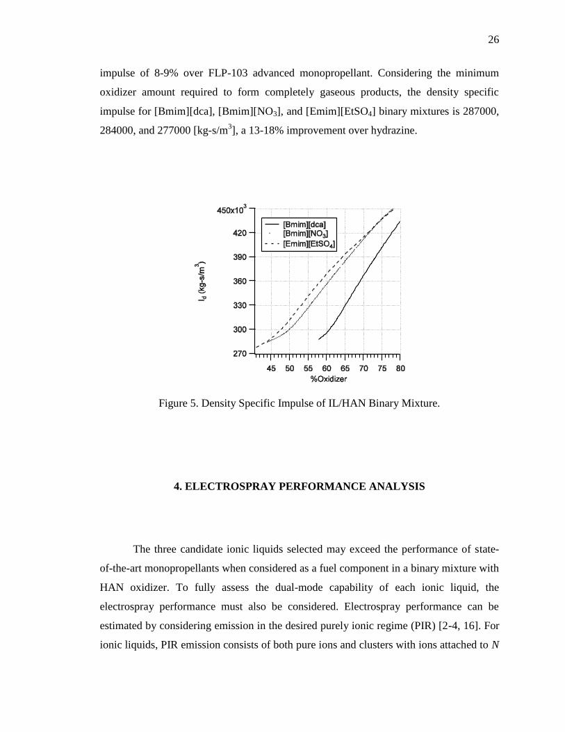
26
impulse of 8-9% over FLP-103 advanced monopropellant. Considering the minimum
oxidizer amount required to form completely gaseous products, the density specific
impulse for [Bmim][dca], [Bmim][NO3], and [Emim][EtSO4] binary mixtures is 287000,
284000, and 277000 [kg-s/m3], a 13-18% improvement over hydrazine.
Figure 5. Density Specific Impulse of IL/HAN Binary Mixture.
4. ELECTROSPRAY PERFORMANCE ANALYSIS
The three candidate ionic liquids selected may exceed the performance of state-
of-the-art monopropellants when considered as a fuel component in a binary mixture with
HAN oxidizer. To fully assess the dual-mode capability of each ionic liquid, the
electrospray performance must also be considered. Electrospray performance can be
estimated by considering emission in the desired purely ionic regime (PIR) [2-4, 16]. For
ionic liquids, PIR emission consists of both pure ions and clusters with ions attached to N

27
number of neutral pairs. Typically, ionic liquids that achieve PIR emit mostly ions (N=0)
and ions attached to a single neutral pair (N=1), although small amounts of the third ion
state (N=2) are also detected [16]. The actual ratio of N=0 to N=1 states in an electrospray
emission is determined experimentally. Furthermore, experiments have shown that this
ratio cannot be controlled, but rather for a stable emission a single ratio is preferred and
may be related to the thermal stability of the ion clusters [63]. Of the few ionic liquids
that have achieved emission in the PIR regime, the ratio of pure ions (N=0) to ions in the
first solvated state (N=1) generally lies between 0.5 and 0.7 [20]. The number of N=2
states or greater is typically less than 5% of the total emission current. Additionally, for a
single ionic liquid, this ratio may also vary depending on the polarity of the extractor, but
again the ratio falls within the same bounds.
Electrospray performance in the PIR regime can be estimated by the following
methods. First, since the number of N=2 states is typically small, it is ignored. The
specific impulse for an emission consisting of the first two ion states is given by [2-4]
, 0 , 1
0
(1 )e N A e N A
sp
V R V RI
g
(9)
where RA is the fraction of the flow that is pure ions. For an electrostatic device, the
following relations hold [10]. The velocity of a charged particle accelerated through a net
potential is given by
2
e
eV
m
(10)
The power supplied to the system is related to thrust and specific impulse by
0
1
2sys sys spP FI g (11)
28
Thrust is therefore inversely proportional to specific impulse for an electrostatic thruster
regardless of the ionization method. The total mass flow rate required to produce the
given thrust is calculated by
0tot spF m I g (12)
where the total mass flow rate is the sum of the mass flow from all electrospray emitters
tot emit emitm N m (13)
The mass flow produced by a single emitter is related to the current produced by a single
emitter by
emitemit
I mm
e (14)
4.1. ELECTROSPRAY SYSTEM PARAMETERS
The relations described in Eqs. (9)-(14) are used to estimate the electrospray
propulsion performance of the three ionic liquid fuels analyzed in the previous sections.
In terms of electrospray operation, two parameters govern the performance of the
thruster: current per emitter and extraction voltage. For this analysis, these parameters are
held constant in order to discern the effect of the propellant on total system performance
and mass. Improvements in the current electrospray technology level will affect all
propellants the same [2-4], provided it is not the physical properties of the propellant that
drive the technology improvement; therefore, for this analysis it is prudent to use constant
system parameters with respect to estimated current technology levels. The possibility of
the physical properties affecting the current and extraction voltage will be discussed in a
later section. Emitters being investigated for PIR electrospray devices can emit a current
on the order of 1 μA per emitter [20]. Also, typical extraction voltages range from 1.5 to
2.5 kV [16, 20]. Therefore, in this analysis, a current of 1 μA per emitter and an

29
extraction voltage of 2000 V will be used for all calculations. The final consideration
made is with respect to the operation mode of the thruster. An alternating polarity (AC)
mode has been selected because both positive and negative ions are extracted. This is
most likely the mode in which future electrospray systems will operate because all of the
propellant is extracted, it provides a net neutral beam, and it generally avoids the problem
of electrochemical fouling. The result of AC operation is an averaged thrust and specific
impulse of the emitted cations and anions. Finally, although the actual ratio of ions to
clusters of ions is not constant with respect to polarity, for simplification and because
these ratios are not known for new ionic liquids it is assumed to be the same for either
cation or anion emission.
4.2. ELECTROSPRAY PERFORMANCE OF SINGLE IONIC LIQUIDS
The electrospray performance of the three ionic liquid fuels alone is computed
through the aforementioned analysis techniques and conditions. Throughout the analysis,
the ionic liquids [Emim][Im] and HAN have been shown for comparison. From Eqs. (9)-
(14), it is seen that the electrospray performance when all system parameters are held
constant is a function of the propellant mass alone. The cation and anion masses for each
propellant used in this study are given in Table 4.
Table 4. Mass Data for Ionic Liquid Propellants
Propellant Chemical Formula MW [g/mol]
Cation Anion Cation Anion
[Bmim][dca] C8H15N2 C2N3 139 66
[Bmim][NO3] C8H15N2 NO3 139 62
[Emim][EtSO4] C6H11N2 C2H5SO4 111 125
[Emim][Im] C6H11N2 C2NF6S2O4 111 280
HAN NH3OH NO3 34 62
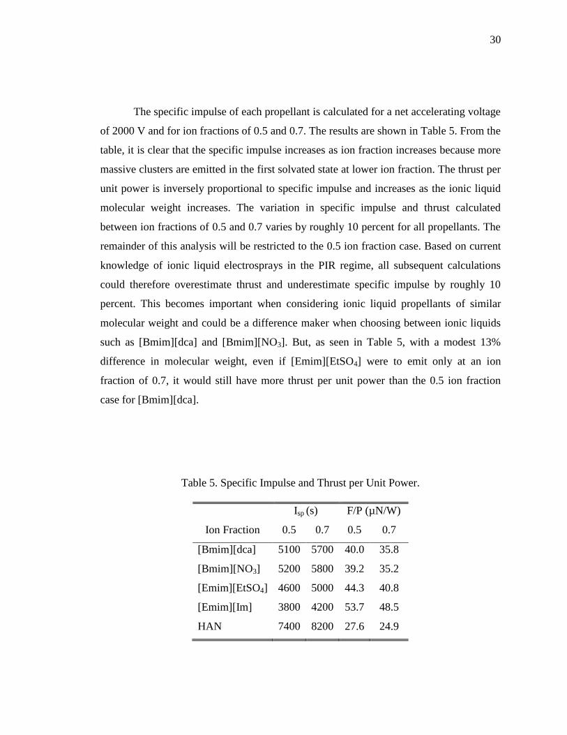
30
The specific impulse of each propellant is calculated for a net accelerating voltage
of 2000 V and for ion fractions of 0.5 and 0.7. The results are shown in Table 5. From the
table, it is clear that the specific impulse increases as ion fraction increases because more
massive clusters are emitted in the first solvated state at lower ion fraction. The thrust per
unit power is inversely proportional to specific impulse and increases as the ionic liquid
molecular weight increases. The variation in specific impulse and thrust calculated
between ion fractions of 0.5 and 0.7 varies by roughly 10 percent for all propellants. The
remainder of this analysis will be restricted to the 0.5 ion fraction case. Based on current
knowledge of ionic liquid electrosprays in the PIR regime, all subsequent calculations
could therefore overestimate thrust and underestimate specific impulse by roughly 10
percent. This becomes important when considering ionic liquid propellants of similar
molecular weight and could be a difference maker when choosing between ionic liquids
such as [Bmim][dca] and [Bmim][NO3]. But, as seen in Table 5, with a modest 13%
difference in molecular weight, even if [Emim][EtSO4] were to emit only at an ion
fraction of 0.7, it would still have more thrust per unit power than the 0.5 ion fraction
case for [Bmim][dca].
Table 5. Specific Impulse and Thrust per Unit Power.
Isp (s) F/P (µN/W)
Ion Fraction 0.5 0.7 0.5 0.7
[Bmim][dca] 5100 5700 40.0 35.8
[Bmim][NO3] 5200 5800 39.2 35.2
[Emim][EtSO4] 4600 5000 44.3 40.8
[Emim][Im] 3800 4200 53.7 48.5
HAN 7400 8200 27.6 24.9
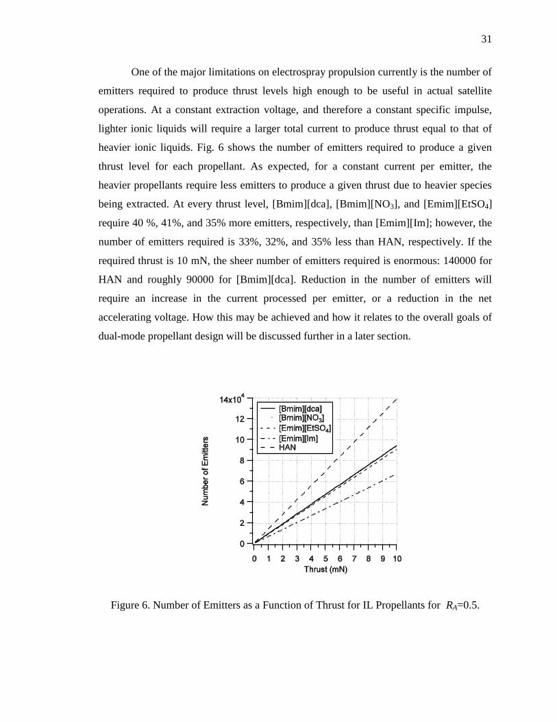
31
One of the major limitations on electrospray propulsion currently is the number of
emitters required to produce thrust levels high enough to be useful in actual satellite
operations. At a constant extraction voltage, and therefore a constant specific impulse,
lighter ionic liquids will require a larger total current to produce thrust equal to that of
heavier ionic liquids. Fig. 6 shows the number of emitters required to produce a given
thrust level for each propellant. As expected, for a constant current per emitter, the
heavier propellants require less emitters to produce a given thrust due to heavier species
being extracted. At every thrust level, [Bmim][dca], [Bmim][NO3], and [Emim][EtSO4]
require 40 %, 41%, and 35% more emitters, respectively, than [Emim][Im]; however, the
number of emitters required is 33%, 32%, and 35% less than HAN, respectively. If the
required thrust is 10 mN, the sheer number of emitters required is enormous: 140000 for
HAN and roughly 90000 for [Bmim][dca]. Reduction in the number of emitters will
require an increase in the current processed per emitter, or a reduction in the net
accelerating voltage. How this may be achieved and how it relates to the overall goals of
dual-mode propellant design will be discussed further in a later section.
Figure 6. Number of Emitters as a Function of Thrust for IL Propellants for RA=0.5.
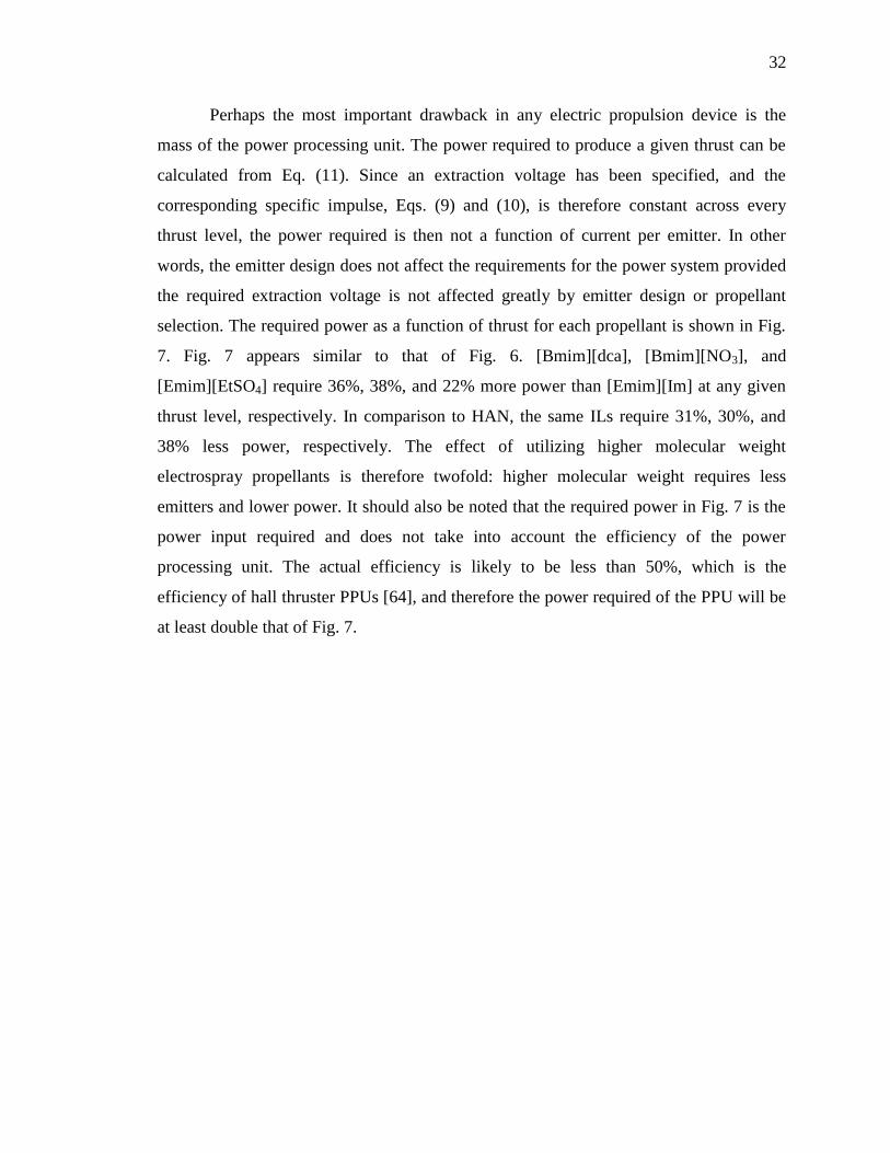
32
Perhaps the most important drawback in any electric propulsion device is the
mass of the power processing unit. The power required to produce a given thrust can be
calculated from Eq. (11). Since an extraction voltage has been specified, and the
corresponding specific impulse, Eqs. (9) and (10), is therefore constant across every
thrust level, the power required is then not a function of current per emitter. In other
words, the emitter design does not affect the requirements for the power system provided
the required extraction voltage is not affected greatly by emitter design or propellant
selection. The required power as a function of thrust for each propellant is shown in Fig.
7. Fig. 7 appears similar to that of Fig. 6. [Bmim][dca], [Bmim][NO3], and
[Emim][EtSO4] require 36%, 38%, and 22% more power than [Emim][Im] at any given
thrust level, respectively. In comparison to HAN, the same ILs require 31%, 30%, and
38% less power, respectively. The effect of utilizing higher molecular weight
electrospray propellants is therefore twofold: higher molecular weight requires less
emitters and lower power. It should also be noted that the required power in Fig. 7 is the
power input required and does not take into account the efficiency of the power
processing unit. The actual efficiency is likely to be less than 50%, which is the
efficiency of hall thruster PPUs [64], and therefore the power required of the PPU will be
at least double that of Fig. 7.
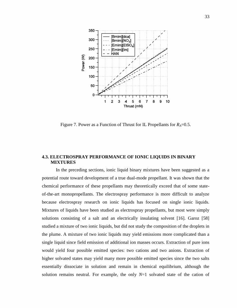
33
Figure 7. Power as a Function of Thrust for IL Propellants for RA=0.5.
4.3. ELECTROSPRAY PERFORMANCE OF IONIC LIQUIDS IN BINARY
MIXTURES
In the preceding sections, ionic liquid binary mixtures have been suggested as a
potential route toward development of a true dual-mode propellant. It was shown that the
chemical performance of these propellants may theoretically exceed that of some state-
of-the-art monopropellants. The electrospray performance is more difficult to analyze
because electrospray research on ionic liquids has focused on single ionic liquids.
Mixtures of liquids have been studied as electrospray propellants, but most were simply
solutions consisting of a salt and an electrically insulating solvent [16]. Garoz [58]
studied a mixture of two ionic liquids, but did not study the composition of the droplets in
the plume. A mixture of two ionic liquids may yield emissions more complicated than a
single liquid since field emission of additional ion masses occurs. Extraction of pure ions
would yield four possible emitted species: two cations and two anions. Extraction of
higher solvated states may yield many more possible emitted species since the two salts
essentially dissociate in solution and remain in chemical equilibrium, although the
solution remains neutral. For example, the only N=1 solvated state of the cation of
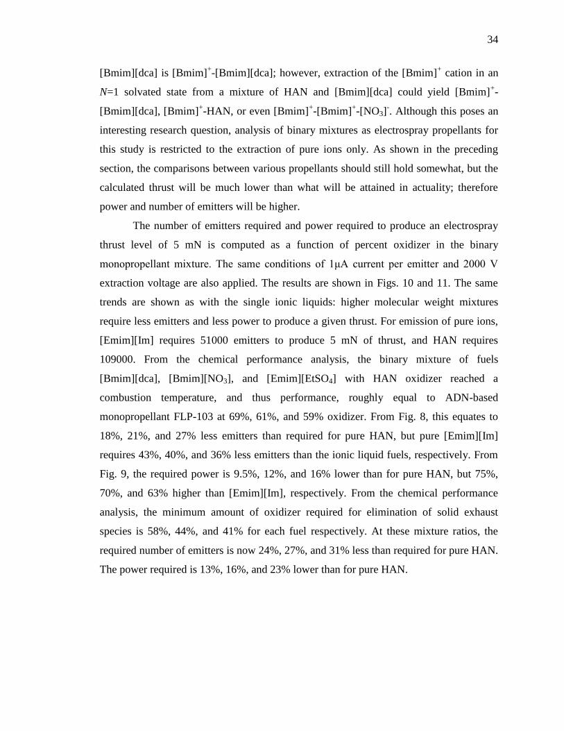
34
[Bmim][dca] is [Bmim]+-[Bmim][dca]; however, extraction of the [Bmim]
+ cation in an
N=1 solvated state from a mixture of HAN and [Bmim][dca] could yield [Bmim]+-
[Bmim][dca], [Bmim]+-HAN, or even [Bmim]
+-[Bmim]
+-[NO3]
-. Although this poses an
interesting research question, analysis of binary mixtures as electrospray propellants for
this study is restricted to the extraction of pure ions only. As shown in the preceding
section, the comparisons between various propellants should still hold somewhat, but the
calculated thrust will be much lower than what will be attained in actuality; therefore
power and number of emitters will be higher.
The number of emitters required and power required to produce an electrospray
thrust level of 5 mN is computed as a function of percent oxidizer in the binary
monopropellant mixture. The same conditions of 1μA current per emitter and 2000 V
extraction voltage are also applied. The results are shown in Figs. 10 and 11. The same
trends are shown as with the single ionic liquids: higher molecular weight mixtures
require less emitters and less power to produce a given thrust. For emission of pure ions,
[Emim][Im] requires 51000 emitters to produce 5 mN of thrust, and HAN requires
109000. From the chemical performance analysis, the binary mixture of fuels
[Bmim][dca], [Bmim][NO3], and [Emim][EtSO4] with HAN oxidizer reached a
combustion temperature, and thus performance, roughly equal to ADN-based
monopropellant FLP-103 at 69%, 61%, and 59% oxidizer. From Fig. 8, this equates to
18%, 21%, and 27% less emitters than required for pure HAN, but pure [Emim][Im]
requires 43%, 40%, and 36% less emitters than the ionic liquid fuels, respectively. From
Fig. 9, the required power is 9.5%, 12%, and 16% lower than for pure HAN, but 75%,
70%, and 63% higher than [Emim][Im], respectively. From the chemical performance
analysis, the minimum amount of oxidizer required for elimination of solid exhaust
species is 58%, 44%, and 41% for each fuel respectively. At these mixture ratios, the
required number of emitters is now 24%, 27%, and 31% less than required for pure HAN.
The power required is 13%, 16%, and 23% lower than for pure HAN.
35
Figure 8. Number of Emitters Required to Produce 5 mN of Thrust as a Function of
Percent HAN Oxidizer for IL Binary Mixtures.
Figure 9. Required Power to Produce 5 mN of Thrust as a Function of Percent HAN
Oxidizer for IL Binary Mixtures.

36
5. DISCUSSION
The results of the chemical performance analysis are promising for dual-mode
propulsion since the performance of high-molecular weight ionic liquids as fuel
components in a binary monopropellant mixture theoretically exceeds the performance of
some state-of-the-art advanced monopropellants. The electrospray performance of these
ionic liquids is promising and may yield higher performance than the current state of the
art, but also may be limited by current technology levels. The results of the preceding
sections are discussed and overall feasibility of imidazole-based ionic liquids as dual-
mode propellants is assessed. Finally, using the results of this paper, trends are discussed
and extrapolated into a selection guide for future dual-mode propellant development.
5.1. IMIDAZOLE BASED IONIC LIQUIDS AS MONOPROPELLANTS
Although these ionic liquids have favorable physical properties toward
electrospray propulsion, considering solely a thermal decomposition of the ionic liquids
as monopropellants shows poor performance in terms of specific impulse, but slightly
more acceptable performance in terms of density specific impulse as all of the ionic
liquids in the study have greater density than hydrazine. However, this must be re-
examined considering the fact that a shifting equilibrium assumption was employed due
to the solid carbon present in the exhaust. Typically, shifting equilibrium specific impulse
is an over-estimate of actual specific impulse. Sutton [10] suggests that this is a 1-4%
over-estimate. If this is taken as 4%, the highest performing ionic liquid, [Bmim][NO3],
now falls 9% below hydrazine in terms of density specific impulse and 22% below
hydrazine in terms of specific impulse. The solid carbon formation in the exhaust gases
leads to the poor performance directly. Furthermore, solid exhaust particles are also
objectionable in many spacecraft applications because they degrade functional surfaces
such as lenses and solar cells [10], and could cause a cloud of orbital debris. And, for
monopropellant thrusters, solid particles may agglomerate on the catalyst bed, rendering
it unusable. The solid carbon formation in decomposition of the ionic liquids is a direct

37
result of the lack of oxidizer present in the anion compared to the large organic alkyl
substituted chains in the cation for the imidazole-based ionic liquids. While these high
molecular weight organic chains are favorable for electrospray propulsion application,
they are detrimental to the chemical aspect of a dual mode system. The highest
performing ionic liquid is [Bmim][NO3], which contains three oxygen atoms that form
small amounts of water and carbon monoxide that lead to its higher performance. Despite
having an additional oxygen atom, the large negative heat of formation of
[Emim][EtSO4] produces a lower overall energy release, and therefore leads to its poor
performance. [Bmim][dca] performs slightly better than [Emim][EtSO4] because it has a
large, positive heat of formation despite containing zero oxidizing components. In order
for a single imidazole-based ionic liquid to achieve even acceptable chemical
performance, it must have enough oxygen to eliminate the solid carbon species in the
exhaust. Ideally, in terms of just chemical performance, this type of ionic liquid will also
contain a high number of nitrogen bonds, and therefore higher heat of formation [65].
5.2. BINARY MIXTURES OF IONIC LIQUIDS AS MONOPROPELLANTS
Imidazole-based ionic liquids as fuel components in a binary mixture with HAN
oxidizer may be a viable option for dual-mode monopropellants. The specific impulse
computed via the shifting equilibrium assumption at a combustion temperature of roughly
1900 K for the ionic liquid monopropellant blends is 1-4% higher than that of FLP-103,
and roughly equal to that of FLP-103 with a frozen flow assumption. This is a feat
considering the predicted combustion temperature for FLP-103 is actually 2000 K. The
reason for the improved performance of the ionic liquid monopropellant blends is the
combustion products that are formed. At the conditions producing a 1900 K chamber
temperature, the binary ionic liquid mixtures form incompletely oxidized species CO, H2,
and N2, as shown in Fig. 4. By contrast, the ADN-based monopropellants such as FLP-
103 have been specifically designed to provide a complete combustion with major
products CO2, H2O, and N2 [12]. Examination of Eq. (5) shows that lower molecular
weight exhaust products yield higher specific impulses. The lower molecular weight
combustion products of the binary ionic liquid mixtures lead to higher specific impulse
38
despite slightly lower combustion temperature compared to FLP-103. In terms of density
specific impulse, the binary mixtures of ionic liquids have 8-9% greater than that of FLP-
103 for the frozen flow assumption, which yielded roughly equal specific impulse. The
main consideration here is the ingredients in each mixture. The density of the fuel
component, methanol, in FLP-103 is 0.79 [g/cc] [57]. The ionic liquid fuels have a much
higher density, making their use as fuel components in a monopropellant mixture
attractive. Additionally, FLP-103 contains a large amount of water, which also lowers the
density of the mixture.
These types of binary mixtures have been shown to be advantageous in terms of
performance, but practically they must be chemically compatible and also be thermally
stable and readily ignitable. As mentioned previously, mixtures of [Bmim][dca] with
HAN have notably shown no visible reactivity, leading to the possibility that they may
indeed be thermally stable at room temperature. However, this represents somewhat of an
unknown presently as this has not been measured quantitatively. Literature suggests that
mixtures of ammonium salts with dicyanamide anions may not be compatible [66-69].
[Bmim][NO3] or [Emim][EtSO4] may be compatible with HAN, but HAN may not be
miscible in either liquid, requiring a third liquid solvent which may be undesirable.
Furthermore, it is also unknown whether these mixtures will ignite either thermally or
catalytically at reasonable temperatures (typically < 2000C). These ignition methods
represent the most common and reliable means of igniting a monopropellant and
verification of this is a major milestone in any monopropellant development effort.
5.3. IMIDAZOLE-BASED IONIC LIQUIDS AS ELECTROSPRAY
PROPELLANTS
In terms of electrospray performance, the ionic liquid fuels investigated show
potential to be higher performing than the current state-of-the-art in electrospray
propellants; however, they may present a challenge in terms of the current technology
levels, if high specific impulse emission is desired. The ionic liquid fuels investigated in
this study have the potential to have higher performance, and also greater flexibility, than
the current state-of-art electrospray propellant [Emim][Im]. This is a direct result from
the lower molecular weight of the investigated ionic liquids compared to [Emim][Im].
39
However, low molecular weight may be a detriment to electrospray propulsion overall, as
evidenced by the pure number of emitters and power required as shown in Figs. 6-9.
Considering the number of emitters required to produce thrust levels typical of electric
propulsion missions shows this effect. To produce 10 mN of thrust with emission of half
N=0 ions and half N=1 ion clusters, [Emim][Im] requires 67000 emitters. If the current
technology limit is taken as 13000 emitters per cm2
[70], this equates to a total area of 5.2
cm2 for [Emim][Im]. The 200 W SPT-35 Hall thruster has an area of 9.6 cm
2 and
produces a comparable thrust of 11 mN [71]. By contrast, purely ionic emission of HAN
at an ion fraction of 0.5 requires a total area of 10.8 cm2 to produce 10 mN of thrust.
While the number of emitters can be effectively reduced by a deceleration grid [72], this
adds complexity to the system, and requires even more power. Even without a
deceleration grid, considering a PPU of equal efficiency to a typical hall thruster (~50%)
[Emim][Im] requires 370 W to produce 10 mN of thrust, while HAN requires 730 W.
The trend is clear: irrespective of technological advances, higher molecular weight
propellants are more advantageous in terms the hardware and power requirements on
electrospray systems.
The large power requirements precluded by emission in the PIR may be
detrimental overall to dual-mode if the molecular weight is lower than state-of-the-art
propellants. This is a direct consequence of the required extraction voltage to produce a
PIR emission, typically 1.5-2.5 kV, which without a deceleration grid produces a high
specific impulse. However, designers have the option to operate the system in the droplet
regime, which may ultimately be a viable option, especially on first generation dual-mode
systems. As mentioned, operation in the droplet mode usually results in very low specific
impulse compared to the PIR, but produces more thrust due to higher mass to charge
ratio. Furthermore, the size of droplets, and therefore the specific impulse, can be
controlled without the addition of a deceleration grid. For example, the ionic liquid
[Emim][Beti] has experimentally reached a specific impulse from less than 200 seconds
and 2.7 µN per emitter up to 1500 seconds and 0.79 µN per emitter have been attained in
the droplet regime [73]. It should be noted, however, that the highest specific impulse in
the droplet regime was obtained by increasing the backing pressure at an emitter
temperature above which PIR was attained. Additionally, the lower efficiency in droplet
40
mode lowered the thrust per emitter to levels equal to the PIR attained by further heating
of the emitter, but at much higher specific impulse (~2300 sec). Therefore, while the
droplet mode may be easier to achieve, the most flexible and highest performing dual-
mode propellants will be able to achieve the PIR.
One of the assumptions made in this analysis was that all propellants could emit at
the same current per emitter. In reality, with current state-of-the-art emitter technology
considered, this may not be entirely the case. In perhaps the most promising advancement
in emitter technology for dual-mode purpose, Legge and Lozano [20] use a porous metal
emitter geometry to produce PIR electrospray emission. What was most intriguing was
that with this geometry, the same heavier, less electrically conductive ionic liquids that
required a preheat of over 200oC were able to emit in the purely ionic regime at room
temperature. However, the current emitted was much less at the same extraction voltage
in comparison to lighter molecular weight propellants such as [Emim][BF4]. The higher
molecular weight propellants will therefore require either higher extraction voltage or
heating of the emitter to produce the same current per emitter as lighter, less viscous and
more electrically conductive propellants. Each propellant, however, still required roughly
1.5 kV extraction voltage to begin emission. So, while the number of emitters could be
reduced if the propellant is less viscous and also more electrically conductive, the power
requirements should remain roughly the same even without heating the emitter. However,
emitter technology, especially the novel porous metal emitter described here, is still very
much in its infancy and these conclusions could eventually change.
5.4. BINARY MIXTURES OF IONIC LIQUIDS AS ELECTROSPRAY
PROPELLANTS
The chemical performance of ionic liquids in binary mixtures is promising;
however achieving high specific impulse with current technology in the electrospray
mode may present more of a challenge than for a single ionic liquid. The reason is the
same as discussed above: the low molecular weight of the propellants. This issue is
compounded by adding ionic oxidizers, such as HAN or ADN, which have a much lower
molecular weight than even the ionic liquid fuels investigated in this paper. To achieve
chemical performance equal to ADN-based FLP-103, the number of emitters required to
41
produce 5 mN of thrust is 88000, 82000, and 79000 emitters when using [Bmim][dca],
[Bmim][NO3], and [Emim][EtSO4] as fuels, respectively, but assuming only ions are
emitted. Therefore, to achieve equal chemical and electrospray performance,
[Emim][EtSO4] requires 10% less emitters than [Bmim][dca], thereby saving roughly
10% mass in terms of the emitter hardware. Additionally, considering the minimum
amount of oxidizer to achieve no solid carbon in the theoretical exhaust species,
[Emim][EtSO4] will require nearly 15% less emitters than [Bmim][dca]. In terms of
power requirements, at the condition where chemical performance is greater than FLP-
103, [Emim][EtSO4] requires 7% less power than [Bmim][dca]. At the minimum oxidizer
amount, [Emim][EtSO4] requires 15% less power than [Bmim][dca]. It is therefore more
ideal for dual-mode propellant blends to use fuels with high molecular weight, but that
have a higher oxygen balance, as equal performance may be obtained in both modes, but
with a reduction in electrospray hardware.
5.5. CONSIDERATIONS FOR DUAL-MODE PROPELLANT DESIGN
Based on the results presented in this paper there are two logical methods to
achieving a workable dual-mode propellant: a single, oxygen-balanced, task specific
ionic liquid or a mixture of two or more ionic liquids. While this may seem to not depart
from conventional wisdom in energetic ionic liquid monopropellant design, when viewed
as a dual-mode propellant the requirements will have to change somewhat. Based on the
results described in the above paragraphs, expected properties and performance
characteristics in terms of what can be reasonably expected at current technology levels
for each method are shown in Table 6.
42
Table 6. Estimated Attainable Physical Properties and Performance Characteristics of
Imidazole-based Dual-Mode Propellants.a
Physical Properties Single Ionic Liquid Binary Mixture
melting point < 2oC < 2
oC
density < 1.4 g/cm3 > 1.4 g/cm
3
viscosity < 100 cP < 100 cP
surface tension < 100 dyne/cm < 100 dyne/cm
electrical conductivity < 1 S/m ~ 1 S/m
thermal stability
< TPIRb
> TPIR
molecular weight > MWSOA < MWSOA
heat of formation Negative Negative
< ΔHfo
,SOA ~ ΔHfo
,SOA
Performance Properties
chemical Isp > 270 sec > 250 sec
combustion temperature > 2500 K > 1900 K
electrical Isp 200-1500 sec 200-5000 sec
power required < PSOA > PSOA
emitters required < NSOA > NSOA
aSOA=State-of-the-Art bCapillary emitter
In terms of pure performance, the ultimate in dual-mode propellants may be a
single liquid which would provide enough oxidizer in the anion to combust to gaseous
products CO, H2, and N2, while still retaining reasonable electrospray properties. This
would not only provide good chemical performance, but inherently this would also be a
high-molecular weight propellant assuming [Emim]+ or higher molecular weight cations
were used. This idea of an oxygen-balanced ionic liquid as a chemical monopropellant is
not new, as attempts have been made to synthesize such a liquid for energetic use [74-
76]. The ionic liquids in [74] were based on lanthanide nitrate complex anions and either
triazole- or tetrazole-based cations. The ionic liquids in [75] were imidazole-based. Many
of the liquids in these efforts were not thermally stable, but a few of these ionic liquids
43
were reportedly stable at room temperature, for example 1-ethyl-3-methylimidazolium
tetranitratoaluminate (C6H11N6AlO12). An ionic liquid of the same anion synthesized by
Jones, et. al. [76], 1- ethyl-4,5-dimethyltetrazolium tetranitratoaluminate
(C5H11N8AlO12), had a chemical specific impulse of 280 seconds, but at a combustion
temperature of 2800 K, well above the sintering temperature of current catalyst bed
technology. Furthermore, these are not ideal spacecraft monopropellants as their
combustion forms a significant amount of solid products, such as Al2O3, which are
objectionable in many spacecraft applications, as mentioned previously [10]. It is
unknown to this point whether these propellants have the electrochemical properties
required for electrospray propulsion. However, based on trends reported for many
imidazole-based ionic liquids these can be reasonably inferred qualitatively and
commented upon. In general, ionic liquids with large, bulky anions have both lower
electrical conductivity and lower surface tension [5, 6]. Additionally, increasing the size
of the cation for imidazole-based liquids always decreases the surface tension and
electrical conductivity. This is in an almost direct contradiction to what is typically
preferred in energetic ionic liquid design. Making use of an increased alkyl chain size in
the cation or increased number of N-N bonds in the anion, therefore raising the heat of
formation of the liquid combined with the requirement for oxygen balance is actually
detrimental to the minimum performance requirements to achieve PIR for electrospray
propulsion: high surface tension and high electrical conductivity.
Perhaps the most important consideration to be made in the early stages of dual-
mode propellant design is actually the thermal stability of ionic liquids. The high thermal
stability of ionic liquids compared to more traditional energetic materials is usually
viewed as a benefit rather than a strict requirement. For dual-mode propellants, this will
be a requirement. The reason is that larger molecular weight propellants will inevitably
require the emitter to be preheated due to their inherently low surface tension and
electrical conductivity. As mentioned, in some cases this has been found to be greater
than 200oC, which actually is above or near the decomposition temperature of many
energetic ionic liquids that have been synthesized [77]. It is therefore likely that with
current emitter technology, oxygen-balanced ionic liquids may be limited to emission in a
droplet regime rather than PIR. Based on the discussion above, to produce an oxygen-
44
balanced ionic liquid with improved performance over state-of-the-art will require a
higher technology level than is currently available on either chemical monopropellant or
electrospray thrusters. The inherently high combustion temperature of currently
synthesized oxygen-balanced ionic liquids is far above that of current monopropellants,
and the lower thermal stability compared to state-of-the-art electrospray propellants could
pose issues in attaining high-specific impulse emissions. As mentioned, with porous
metal emitters the latter could be avoided, but at the cost of lower current per emitter. If
the emitter preheat temperature is limited due to the thermal stability consideration when
spraying an energetic ionic liquid rather than a much more stable fluorinated ionic liquid,
then either the extraction voltage or the number of emitters will have to be increased to
compensate. Higher power requirements compared to state-of-the-art electrospray
propellants may therefore be inevitable for a dual-mode monopropellant/electrospray
system if specific impulse near the state-of-the art in each mode individually is desired.
Ultimately, considering the lower-specific impulse droplet mode for these types of ionic
liquids may be more advantageous given the reduction in thruster hardware, but will
depend on the desired mission capabilities.
In this paper, the method of combining a fuel-rich ionic liquid with an ionic
oxidizer such as HAN or ADN as means of obtaining a workable dual-mode propellant is
presented. This may be a much simpler method than developing a task-specific ionic
liquid because the anticipated physical properties are closer to the present state-of-the-art
in both modes. It was shown that in order to obtain performance closer to state-of-the-art
more power and emitters will be necessary given the low molecular weight of the
oxidizer. However, PIR is likely easier to achieve, given that both HAN and an ionic
liquid fuel have electrical conductivities near 1 S/m [78], therefore requiring a reduced
emitter preheat compared to oxygen-balanced ionic liquids. The main challenge for this
method will be the chemical compatibility and also the miscibility of the oxidizer in the
ionic liquid fuel. To be even usable in the electrospray mode, it is absolutely paramount
that no portion of the mixture be volatile, which departs from conventional ‘green’
monopropellants which make use of both water and a volatile fuel. While it may be
possible that the addition of water to a certain ionic liquid system may show azeotropic
behavior, this is difficult to assess and even in the best case scenario will be detrimental
45
to electrospray performance as a whole. When selecting candidate ionic liquid fuels,
liquids that have a higher oxygen balance will be more promising when considering the
dual-mode system as a whole. The main reason, as discussed is the fact that a smaller
amount of the lower molecular weight oxidizer is required. However, an interesting point
can be made when considering the minimum amount of oxidizer required. Although the
chemical performance drops, mass can be saved on the electrospray system and therefore
the potential for increased flexibility in the design choices exists.
6. CONCLUSIONS
Imidazole based ionic liquids have been examined as potential candidates for
dual-mode chemical monopropellant and electrospray propulsion. Physical properties
required of ionic liquids for dual-mode spacecraft propulsion are high density, low
melting temperature, high electrical conductivity, high surface tension, and high
molecular weight. These properties should be comparable to current state-of-the-art
propellants hydrazine and [Emim][Im] for the chemical and electrical modes,
respectively. Three generic, sample ionic liquids were identified that exceed or are close
to meeting the physical property criteria: [Bmim][dca], [Bmim][NO3], and
[Emim][EtSO4].
Theoretical chemical performance was calculated for these ionic liquids using the
NASA CEA computer code and performance equations. Considering these ionic liquids
as monopropellants shows that they do not perform well compared to hydrazine and will
be essentially unusable due to the large amounts of solid carbon predicted in the exhaust
species. Considering the ionic liquids as fuel components in a binary monopropellant
mixture with 60-70% HAN oxidizer shows performance exceeding that of ADN-based
monopropellants. Ionic liquid fuel components with more oxidizing elements in the anion
require less additional HAN oxidizer to form gaseous CO, and thus achieve an acceptable
level of performance.
46
Examination of the electrospray performance of these ionic liquids shows that
they may compete with current state-of-the-art propellants with improvements in
technology. High molecular weight propellants reduce the number of required
electrospray emitters, while also requiring higher power. The addition of a lower
molecular weight oxidizer to an imidazole-based ionic liquid fuel increases the number of
emitters required, but is necessary to obtain good chemical performance. Ionic liquid fuel
components with oxidizing components in the anion require less additional oxidizer to
achieve similar chemical performance, thereby reducing the number of required emitters
for electrospray propulsion. By extension, in terms of pure performance oxygen-balanced
ionic liquids may be the ultimate in dual mode propulsion as they have the required
oxidizer to combust into complete products, while most likely retaining high molecular
weight favorable to electrospray propulsion.
Two methods typical of design of energetic ionic liquids for monopropellant
applications were discussed: design of a task-specific, oxygen balanced ionic liquid or
design of a mixture of multiple ionic liquids. In terms of performance, a task-specific
ionic liquid will likely outperform any mixture in a dual-mode system, but will require
advances in both monopropellant and electrospray technology to achieve high
performance due to the anticipated high combustion temperature, as well as low thermal
stability compared to estimated required heating of a capillary electrospray emitter to
achieve high-specific impulse PIR emission. A workable dual-mode propellant utilizing
binary mixture of ionic liquids will be easier to achieve given current technology.
Utilization of ionic liquid fuels with higher oxygen balance provided by the anion is
desired when forming binary mixtures with an oxidizer such as HAN, as comparatively
this results in reduction of electrospray hardware, while still achieving equal performance
in both modes compared to more fuel-rich ionic liquid fuels. The drawback is an increase
in required power to achieve high performance electrospray emission compared to state-
of-the-art electrospray-specific propellants due to the low molecular weight of the
additional oxidizer.
47
REFERENCES
[1] Hass, J.M., Holmes, M.R., “Multi-Mode Propulsion System for the Expansion of
Small Satellite Capabilities,” NATO MP-AVT-171-05, 2010.
[2] Donius, B.R. “Investigation of Dual-Mode Spacecraft Propulsion by Means of Ionic
Liquids,” Masters Thesis, Department of Mechanical and Aerospace Engineering,
Missouri University of Science & Technology, Rolla, MO., May 2010.
[3] Donius, B. R., Rovey, J. L., “Ionic Liquid Dual-Mode Spacecraft Propulsion
Assessment,” Journal of Spacecraft and Rockets, Vol. 48, No. 1, 2011, pp. 110-123.
doi:10.2514/1.49959
[4] Donius, B. R., Rovey, J. L., "Analysis and Prediction of Dual-Mode Chemical and
Electric Ionic Liquid Propulsion Performance," 48th Aerospace Sciences Meeting,
AIAA Paper 2010-1328, 2010.
[5] Wilkes, J.S., Wasserscheid, P., Welton, T., Ionic Liquids in Synthesis, 2nd
ed.,
WILEY-VCH Verlag GmbH &Co., 2008, Ch.1.
[6] Freemantle, M. An Introduction to Ionic Liquids, RSC Publishing, 2010.
[7] Plechkova, N. V., Seddon, K. R., “Applications of Ionic Liquids in the Chemical
Industry,” Chemical Society Reviews, Vol. 37, 2008, pp. 132-150.
doi: 10.1039/B006677J
[8] Boatz, J., Gordon, M., Voth, G., Hammes-Schiffer, S., “Design of Energetic Ionic
Liquids,” DoD HPCMP Users Group Conference, IEEE Publ., Piscataway, NJ,
Pittsburgh, 2008, pp. 196-200.
[9] Smiglak, M., Reichert, M. W., Holbrey, J. D., Wilkes, J. S., Sun, L., Thrasher, J. S.,
Kirichenko, K., Singh, S., Katritzky, A. R., Rogers, R. D., “Combustible ionic liquids
by design: is laboratory safety another ionic liquid myth?,” Chemical
Communications, Issue 24, 2006, pp. 2554-2556.
doi: 10.1039/b602086k
[10] Sutton, G. P., Biblarz, O., Rocket Propulsion Elements, 7th
ed., John Wiley & Sons,
New York, 2001, Ch. 5, 7, 19.
48
[11] Amariei, D., Courtheoux, L., Rossignol, S., Batonneau, Y., Kappenstein, C., Ford,
M., and Pillet, N., “Influence of the Fuel on the Thermal and Catalytic
Decompositions of Ionic Liquid Monopropellants,” 41st AIAA Joint Propulsion
Conference, AIAA, Paper 2005-3980, 2005.
[12] Anflo, K., Grönland, T. A., Bergman, G., Johansson, M., Nedar, R., “Towards Green
Propulsion for Spacecraft with ADN-Based Monopropellants,” 38th
AIAA Joint
Propulsion Conference, AIAA Paper 2002-3847, 2002.
[13] Slettenhaar, B., Zevenbergen, J. F., Pasman, H. J., Maree, A. G. M., Moerel, J. L. P.
A. “Study on Catalytic Ignition of HNF Based Non Toxic Monopropellants,” 39th
AIAA Joint Propulsion Conference. AIAA Paper 2003-4920, 2003.[14] Anflo, K.,
Persson, S., Thormahlen, P., Bergman, G., Hasanof, T., “Flight Demonstration of an
ADN-Based Propulsion System on the PRISMA Satellite,” 42nd
AIAA Joint
Propulsion Conference, AIAA Paper 2006-5212, 2006.
[15] Chang, Y. P.,Josten, J. K., Zhang, B. Q., Kuo, K. K., “Combustion Characteristics of
Energetic HAN/Methanol Based Monopropellants,” 38th
AIAA Joint Propulsion
Conference, AIAA Paper 2002-4032, 2002.
[16] Chiu, Y., Dressler, A., “Ionic Liquids for Space Propulsion,” In Ionic Liquids IV:
Not Just Solvents Anymore, ACS Symposium Series, Vol. 975, American Chemical
Society, Washington, DC, 2007, pp. 138-160.
[17] Romero-Sanz, I., Bocanegra, R., Fernandez De La Mora, J., Gamero-Castano, M.,
“Source of Heavy Molecular Ions Based on Taylor Cones of Ionic Liquids Operating
in the Pure Ion Evaporation Regime,” Journal of Applied Physics, Vol. 94, 2003, pp.
3599-3605.
doi: 10.1063/1.1598281
[18] Gamero-Castano, M., “Characterization of a Six-Emitter Colloid Thruster Using a
Torsional Balance,” Journal of Propulsion and Power, Vol. 20, No. 4, 2004, pp.
736-741.
doi: 10.2514/1.2470
49
[19] Larriba, C., Garoz, D., Bueno, C., Romero-Sanz, I., Castro, S., Fernandez de la
Mora, J., Yoshida, Y., Saito, G., Hagiwara, R., Masumoto, K., Wilkes, J., “Taylor
Cones of Ionic Liquids as Ion Sources: The Role of Electrical Conductivity and
Surface Tension,” Ionic Liquids IV: Not Just Solvents Anymore, ACS Symposium
Series, Vol. 975, American Chemical Society, Washington, DC, 2007, Ch. 21.
[20] Legge, R. S., Lozano, P. C., “Electrospray Propulsion Based on Emitters
Microfabricated in Porous Metals,” Journal of Propulsion and Power, Vol. 27, No.
2, 2011, pp. 485-495.
[21] Demmons, N., Hruby, V., Spence, D., Roy, T., Ehrbar, E., Zwahlen, J., Martin, R.,
Ziemer, J., Randolph, T., “ST7-DRS Mission Colloid Thruster Development,” 44th
AIAA Joint Propulsion Conference, AIAA Paper 2008-4823, 2008.
[22] Gamero-Castano, M., Fernandez De La Mora, J., “Direct Measurement of Ion
Evaporation Kinetics from Electrified Liquid Surfaces,” Journal of Chemical
Physics, Vol. 113, 2000, pp. 815-832.
doi: 10.1063/1.481857
[23] Fernandez de la Mora, J., Loscertales, I. G., “The Current Emitted by Highly
Conducting Taylor Cones,” Journal of Fluid Mechanics, Vol. 260, 1994, pp. 155-
184.
doi: 10.1017/s0022112094003472
[24] De Grys, K. H., Wilson, A. C., “Ionic Liquid Multi-Mode Propulsion System,”
Aerojet Corporation, International Patent Application No. PCT/US2009/003732.
Publication No. WO/2010/036291, Jan 2010.
[25] Seddon, K., Stark, A., Torres, M., “Viscosity and Density of 1-Alkyl-3-
methylimidazolium Ionic Liquids”, Clean Solvents, ACS Symposium Series, Vol.
819, American Chemical Society, 2002, Ch. 4.
[26] Emel’yanenko, V. N., Verevkin, S. P., Heintz, A., Schick, C., “Ionic Liquids.
Combination of Combustion Calorimetry with High-Level Quantum Chemical
Calculations for Deriving Vaporization Enthalpies”, Journal of Physical Chemistry
B, Vol. 112, 2008, pp. 8095-8098.
doi: 10.1021/jp802112m
50
[27] Kowsari, M. H., Alavi, S., Ashrafizaadeh, M., Najafi, B., “Molecular Dynamics
Simulation of Imidazolium Based Ionic Liquids. II. Transport Coefficients,” Journal
of Chemical Physics, Vol. 130, 2009.
doi: 10.1063/1.3042279
[28] Mokhtarani, M., Sharifi, A., Mortaheb, H. R., Mirzaei, M., Mafi, M., Sadeghian, F.,
“Density and viscosity of 1-butyl-3-methylimidazolium nitrate with ethanol, 1-
propanol, or 1-butanol at several temperatures,” Journal of Chemical
Thermodynamics, Vol. 41, 2009, pp. 1432-1438.
doi: 10.1016/j.jct.2009.06.02
[29] Fredlake, C. P., Crosthwaite, J. M., Hert, D. G., Aki, S. N. V. K., Brennecke, J. F.,
“Thermophysical Properties of Imidazolium-Based Ionic Liquids,” Journal of
Chemical Engineering Data, Vol. 49, 2004, pp. 954-964.
doi: 10.1021/je034261a
[30] Emel’yanenko, V. N., Verevkin, S. P., Heintz, A., “The Gaseous Enthalpy of
Formation of the Ionic Liquid 1-Butyl-3 methylimidazolium Dicayanamide from
Combustion Calorimetry, Vapor Pressure Measurements, and Ab Initio
Calculations,” Journal of the American Chemical Society, Vol. 129, 2007, No. 13,
pp. 3930-3937.
doi: 10.1021/ja0679174
[31] Zech, O., Stoppa, A., Buchner, R., Kunz, W., “The Conductivity of Imidazolium-
Based Ionic Liquids from (248 to 468) K. B. Variation of the Anion,” Journal of
Chemical Engineering Data, Vol. 55, 2010, pp. 1774-1778.
doi: 10.1021/je900793r
[32] Klomfar, J., Souckova, M., Patek, J., “Temperature Dependence of the Surface
Tension and Density at 0.1 MPa for 1-Ethyl- and 1-Butyl-3-methylimidazolium
Dicyanamide,” Journal of Chemical Engineering Data, Vol. 56, 2011, pp. 3454-
3462.
doi: 10.1021/je200502j
51
[33] Carvalho, P. J., Regueira, T., Santos, L. M. N. B. F., Fernandez, J., Coutinho, J. A.
P., “Effect of Water on the Viscosities and Densities of 1-Butyl-3-
methylimidazolium Dicyanamide and 1-Butyl-3-methylimidazolium
Tricyanomethane at Atmospheric Pressure,” Journal of Chemical Engineering Data,
Vol. 55, 2010, pp. 645-652.
doi: 10.1021/je900632q
[34] Hofman, T., Goldon, A., Nevines, A., Letcher, T. M., “Densities, excess volumes,
isobaric expansivity, and isothermal compressibility of the (1-ethyl-3-
methylimidazolium ethylsulfate + methanol) system at temperatures (283.15 to
333.15) K and pressures from (0.1 to 35) MPa,” Journal of Chemical
Thermodynamics, Vol. 40, 2008, pp. 580-591.
doi: :10.1016/j.jct.2007.11.01
[35] Domanska, U., Laskowska, M., “Phase Equilibria and Volumetric Properties of (1-
Ethyl-3-Methylimidazolium Ethylsulfate + Alcohol or Water) Binary Systems,”
Journal of Solution Chemistry, Vol. 37, Issue 9, 2008 pp. 1271-1287.
doi: 10.1007/s109530089306y
[36] Zhang, Z. H., Tan, Z. C., Sun, L. X., Jia-Zhen, Y., Lv, X. C., Shi, Q.,
“Thermodynamic investigation of room temperature ionic liquid: The heat capacity
and standard enthalpy of formation of EMIES,” Thermochimica Acta, Vol. 447,
2006, pp. 141-146.
doi: 10.1016/j/tca.2006.04.022
[37] Vila, J., Gines, P., Rilo, E., Cabeza, O., Varela, L. M , “Great Increase of the
Electrical Conductivity of Ionic Liquids in Aqueous Solutions,” Fluid Phase
Equilibria, Vol. 247, 2006, pp. 32-39.
doi: 10.1016/j.fluid.2006.05.028
[38] Gomez, E., Gonzalez, B., Calvar, N., Tojo, E., Dominguez, A., “Physical Properties
of Pure 1-Ethyl-3-methylimidazolium Ethylsulfate and Its Binary Mixtures with
Ethanol and Water at Several Temperatures,” Journal of Chemical Engineering
Data, Vol. 51, 2006, pp. 2096-2102.
doi: 10.1021/je060228n
52
[39] Arce, A., Rodil, E., Soto, A., “Volumetric and Viscosity Study for the Mixtures of 2-
Ethoxy-2-methylpropane, Ethanol, and 1-Ethyl-3-methylimidazolium Ethyl Sulfate
Ionic Liquid,” Journal of Chemical Engineering Data, Vol. 51, 2006, pp. 1453-
1457.
doi: 10.1021/je060126x
[40] Schreiner, C., Zugmann, S., Hartl, R., Gores, H. J., “Fractional Walden Rule for
Ionic Liquids: Examples from Recent Measurements and a Critique of the So-Called
Ideal KCl Line for the Walden Plot,” Journal of Chemical Engineering Data, Vol.
55, 2010, pp. 1784-1788.
doi: 10.1021/je900878j
[41] Tokuda, H., Tsuzuki, S., Abu Bin Hasan Susan, M., Hayamizu, K., Watanabe, M.,
“How Ionic Are Room-Temperature Ionic Liquids? An Indicator of the
Physicochemical Properties,” Journal of Physical Chemistry B, Vol. 110, 2006, pp.
19593-19600.
doi: 10.1021/jp064159v
[42] Widegren, J. A., Saurer, E. M., Marsh, K. N., Magee, J. W., “Electrolytic
Conductivity of Four Imidazolium-Based Room-Temperature Ionic Liquids and the
Effect of Water Impurity,” Journal of Chemical Thermodynamics, Vol. 37, 2005,
pp. 569-575.
doi: 10.1016/j.jct.2005.04.009
[43] Carvalho, P. J., Freire, M. G., Marrucho, I. M., Queimada, A. J., Coutinho, J. A. P.,
“Surface Tensions for the 1-Alkyl-3-methylimidazolium
Bis(trifluoromethylsulfonyl)imide Ionic Liquids,” Journal of Chemical Engineering
Data, Vol. 53, 2008, pp. 1346-1350.
doi: 10.1021/je800069z
[44] Gordon, S., “Computer Program for the Calculation of Complex Chemical
Equilibrium Compositions and Applications,” NASA RP-1311-P2, 1996.
[45] Schmidt, E. W., Hydrazine and Its Derivatives: Preparation, Properties,
Applications, Wiley-Interscience, 2001.

53
[46] Vila, J., Gines, P., Pico, J. M., Franjo, C., Jimenez, E., Varela, L. M., Cabeza, O.,
“Temperature dependence of the electrical conductivity in EMIM-based ionic
liquids: Evidence of Vogel–Tamman–Fulcher behavior,” Fluid Phase Equilibria,
Vol. 242, 2006, pp. 141-146.
doi: 10.1016/j.fluid.2006.01.02
[47] Sanchez, L. G., Espel, J. R., Onink, F., Meindersma, G. W., De Haan, A. B.,
“Density, Viscosity, and Surface Tension of Synthesis Grade Imidazolium,
Pyridinium, and Pyrrolidinium Based Room Temperature Ionic Liquids,” Journal of
Chemical Engineering Data, Vol. 54, 2009, pp. 2803-2812.
doi: 10.1021/je800710p
[48] Yan, T., Li, S., Jiang, W., Gao, X., Xiang, B., Voth, G., “Structure of the Liquid-
Vacuum Interface of Room Temperature Ionic Liquids: A Molecular Dynamics
Study,” Journal of Physical Chemistry B, Vol. 110, 2006, pp. 1800-1806.
doi: 10.1021/jp055890p
[49] Fletcher, S. I., Sillars, F. B., Hudson, N. E., Hall, P. J., “Physical Properties of
Selected Ionic Liquids for Use as Electrolytes and Other Industrial Applications,”
Journal of Chemical Engineering Data, Vol. 55, 2010, pp. 778-782.
doi: 10.1021/je900405j
[50] Strechan, A. A., Kabo, A. G., Paulechka, Y. U., Blokhin, A. V., Kabo, G. J.,
Shaplov, A. S., Lozinskaya, E. I., “Thermochemical Properties of 1-butyl-3-
methylimidazolium nitrate”, Thermochimica Acta, Vol. 47, 2008, pp. 25-31.
doi: 10.1016/j.tca.2008.05.002
[51] Stoppa, A., Hunger, J., Buchner, R., “Conductivities of Binary Mixtures of Ionic
Liquids with Polar Solvents,” Journal of Chemical Engineering Data, Vol. 54, 2009,
pp. 472-479.
doi: 10.1021/je800468h
[52] Sanchez, L. G., Espel, J. R., Onink, F., Meindersma, G. W., de Haan, A. B.,
“Density, Viscosity, and Surface Tension of Synthesis Grade Imidazolium,
Pyridinium, and Pyrrolidinium Based Room Temperature Ionic Liquids,” Journal of
Chemical Engineering Data, Vol. 54, 2009, pp. 2803-2812.
doi: 10.1021/je800710p
54
[53] Yoshida, Y., Baba, O., Larriba, C., Saito, G., “Imidazolium-Based Ionic Liquids
Formed with the Dicyanamide Anion: Influence of Cationic Structure on Ionic
Conductivity,” Journal of Physical Chemistry B, Vol. 111, 2007, pp. 12204-12210.
doi: 10.1021/jp0745236
[54] Krummen, M., Wasserscheid, P., Gmehling, J., “Measurement of Activity
Coefficients at Infinite Dilution in Ionic Liquids Using the Dilutor Technique,”
Journal of Chemical Engineering Data, Vol. 47, 2002, 1411-1417.
doi: 10.1021/je0200517
[55] Gomez, E., Gonzalez, B., Calvar, N., Tojo, E., Dominguez, A., “Physical Properties
of Pure 1-Ethyl-3-methylimidazolium Ethylsulfate and Its Binary Mixtures with
Ethanol and Water at Several Temperatures,” Journal of Chemical Engineering
Data, Vol. 51. 2006, pp. 2096-2102.
doi: 10.1021/je060228n
[56] Yang, J., Lu, X., Gui, J., Xu, W., “A new theory for ionic liquids—the Interstice
Model
Part 1. The density and surface tension of ionic liquid EMISE,” Green Chemistry,
Vol. 6, 2004, pp. 541-543.
doi: 10.1039/B412286K
[57] Wingborg, N., Eldsater, C., Skifs, H., “Formulation and Characterization of ADN-
Based Liquid Monopropellants,” 2nd
International Conference on Green Propellants
for Space Exploration, ESA SP-557, 2004.
[58] Garoz, D., Bueno, C., Larriba, C., Castro, S., Fernandez de la Mora, J., “Taylor
Cones of Ionic Liquids from Capillary Tubes as Sources of Pure Ions for Electrical
Propulsion,” 42nd
AIAA Joint Propulsion Conference, AIAA Paper 2006-4639.
[59] “CPIA/M5 Liquid Propellant Engine Manual,” Johns Hopkins University,
Columbia, MD. Chemical Propulsion Information Agency, 1998.
[60] Holbrey, J. D., Rogers, R. D., “Physiochemical Properties of Ionic Liquids: Melting
Points and Phase Diagrams,” In Ionic Liquids in Synthesis, 2nd
ed., WILEY-VCH
Verlag GmbH &Co., 2008, Ch.3.
[61] Klein, N., “Liquid Propellants for Use in Guns-A Review,” BRL-TR-2641, 1985.
55
[62] Dambach, E., Heister, S., Ismail, I., Schneider, S., Hawkins, T., “An Investigation of
Hypergolicity of Dicyanamide-Based Ionic Liquid Fuels with Common Oxidizers,”
Air Force Research Laboratory, AFRL-RZ-ED-TP-2008-371, 2008.
[63] Chiu, Y., Austin, B. L., Dressler, R. A., Levandier, D., Murray, P. T., Lozano, P.,
Martinez-Sanchez, M., “Mass Spectrometric Analysis of Colloid Thruster Ion
Emission from Selected Propellants,” Journal of Propulsion and Power, Vol. 21,
2005, pp. 416-423.
[64] Pencil, E. J., “Recent Electric Propulsion Development Activities for NASA Science
Missions,” IEEE Aerospace Conference, IEEE Publ., March 2009.
[65] Chambreau, S. D., Boatz, J. A., Vaghjiani, G. L., Koh, C., Kostko, O., Golan, A.,
Leone, S. R., “Thermal Decomposition Mechanism of 1-Ethyl-3-methylimidazolium
Bromide Ionic Liquid,” Journal of Physical Chemistry A [online], URL:
http://pubs.acs.org/doi/pdf/10.1021/jp209389d [cited 7 March 2012].
doi: 10.1021/jp209389
[66] Frankel, M. B., Burns, E. A., Butler, J. C., Wilson, E. R., “Derivatives of
Dicyanamide,” Journal of Organic Chemistry, Vol. 28, 1963, pp. 2428.
[67] Jurgens, B. A., Hoppe, H. A., Irran, E., Schnick, W., “Transformation of
Ammonium Dicyanamide in the Solid,” Inorganic Chemistry, Vol. 41, 2002, pp.
4849-4851.
doi: 10.1021/ic025800k
[68] Lotsch, B. V., Schnick, W., “Towards Novel C-N Materials: Crystal Structures of
Two Polymorphs of Guanidinium Dicyanamide and Their Thermal Conversion into
Melamine,” New Journal of Chemistry, Vol. 28, 2004, pp. 1129-1136.
doi: 10.1039/B403788J
[69] Roemer, J. J., Kaiser, D. W., “Reaction product of sodium dicyanamide and
hydroxylamine hydrochloride,” American Cyanamid Co., Old Greenwich, CT, U. S.
Pat. 2648669 (29 May 1951/11 Aug 1953).
[70] Demmons, N., “20 mN Variable Specific Impulse Colloid Thruster,” Busek, Co.,
NASA SBIR Proposal 10-1 S3.04,-8878, Natick, MA, 2010.
[71] Maslennikov, N. A., “Lifetime of the Stationary Plasma Thruster,” 24th
International
Electric Propulsion Conference, IEPC-1995-75, 1995.
56
[72] Coffman, C. S., Courtney, D. G., Hicks, F. M., Jamil, S., Li, H., Lozano, P. C.,
“Progress Toward a Variable Specific Impulse Electrospray Propulsion System,”
47th
AIAA Joint Propulsion Conference, AIAA Paper 2011-5591, 2011.
[73] Romero-Sanz, I., de Carcer, I. A., de la Mora, J. F., “Ionic Propulsion Based on
Heated Taylor Cones of Ionic Liquids,” Journal of Propulsion and Power, Vol. 21,
2005, pp. 239-242.
doi: 10.2514/1.5493
[74] Tao, G-H., Huang, Y., Boatz, J. A., Shreeve, J. M., “Energetic Ionic Liquids Based
on Lanthanide Nitrate Complex Anions,” Chemical European Journal, 2008.
doi: 10.1002/chem.200800828
[75] Christe, K. O., Drake, G. W., “Energetic Ionic Liquids,” United States Air Force,
United States Patent 7771549, Aug 2010.
[76] Jones, C. B., Haiges, R., Schroer, T., Christe, K. O., “Oxygen-Balanced Energetic
Ionic Liquid,” Angewandte Chemie International Edition, Vol. 45, 2006, 4981-4984.
doi: 10.1002/anie.200600735
[77] Zhang, Y., Gao, H., Joo, Y., Shreeve, J. M., “Ionic Liquids as Hypergolic Fuels,”
Angewandte Chemie International Edition, Vol. 50, 2011, 9554-9562.
doi: 10.1002/anie.201101954
[78] Vanderhoff, J. A., Bunte, S. W., “Electrical Conductivity Measurements of
Hydroxylammonium Nitrate: Design Considerations,” U. S. Army Ballistic Research
Laboratory, Rept. BRL-MR-3511, Aberdeen Proving Ground, MD, April 1986.
57
II. Assessment of Multi-Mode Spacecraft Micropropulsion Systems
Steven P. Berg and Joshua L. Rovey
Missouri University of Science and Technology, Rolla, Missouri, 65409
ABSTRACT
Multi-mode spacecraft micropropulsion systems which include a high-thrust
chemical mode and high-specific impulse electric mode are assessed with specific
reference to cubesat-sized satellite applications. Both cold gas Freon-14 propellant and
ionic liquid chemical monopropellant modes were investigated alongside pulsed plasma,
electrospray, and Hall effect electric thruster modes. Systems involving chemical
monopropellants have the highest payload mass fractions for a reference mission of a 500
m/s delta-V and 6U sized cubesat for electric propulsion usage below 70% of total delta-
V, while for higher electric propulsion usage, cold gas thrusters delivered a higher
payload mass fraction due to lower system inert mass. Due to the combination of a
common propellant for both propulsive modes, low inert mass, and high electric thrust,
the monopropellant/electrospray system has the highest mission capability in terms of
delta-V for missions lasting shorter than 150 days.
NOMENCLATURE
Ac = combustion chamber cross sectional area, [m2]
At = throat area, [m2]
CF = thrust coefficient
C = effective exhaust velocity, [m/s]

58
Dc = combustion chamber diameter, [m]
Dt = throat diameter, [m]
EP = electric propulsion usage fraction
F = thrust, [N]
Ftu = ultimate strength of material, [N/m2]
finert = inert mass fraction
fSI = system integration fraction
g0 = acceleration of gravity, [m/s2]
Isp = specific impulse, [s]
Isp,chem = chemical mode specific impulse, [s]
Isp,elec = electric mode specific impulse, [s]
Isp,mm = multi-mode effective specific impulse, [s]
Lc = combustion chamber length, [m]
L*
= characteristic combustion chamber length
m0 = initial mass of spacecraft, [kg]
mc = combustion chamber mass, [kg]
mchem = mass of chemical propellant, [kg]
me = propulsion system mass, [kg]
me,int = integrated propulsion system mass, [kg]
melec = mass of electric propellant, [kg]
mf = final mass of spacecraft, [kg]
mf1 = mass of spacecraft after first burn, [kg]
minert = inert mass, [kg]
mpay = payload mass, [kg]
mPPU = mass of power processing unit, [kg]
mprop = propellant mass, [kg]
msa = mass of solar array, [kg]
mtank = mass of propellant tank, [kg]
Pb = burst pressure, [Pa]
Pc = chamber pressure, [psi]
Pe = nozzle exit pressure, [Pa]
59
Pthr = electric thruster power, [kW]
rc = combustion chamber radius, [m]
rt = throat radius, [m]
tb = thruster burn time [day]
tw = wall thickness, [m]
α = nozzle divergence half-cone angle, [degrees]
ΔV = velocity increment, [m/s]
ε = nozzle expansion ratio
ηp = propulsive efficiency
ηt = thrust efficiency
ηv = mission planning efficiency
θc = convergent section angle, [degrees]
γ = specific heat ratio
λ = nozzle divergence correction factor
φtank = empirical tank sizing parameter
ρprop = propellant density, [kg/m3]
ρw = wall material density, [kg/m3]
1. INTRODUCTION
Multi-mode spacecraft propulsion is the use of two or more propulsive devices on
a spacecraft, specifically making use of a high-thrust, usually chemical, mode and a high-
specific impulse, usually electric mode. This can be beneficial in two primary ways. The
first is to increase the mission flexibility of a single spacecraft architecture in that both
high-thrust and high-specific impulse maneuvers are available to mission designers at
will, perhaps even allowing for drastic changes in the mission plan while on-orbit or with
a relatively short turnaround from concept to launch. The second way a multi-mode
propulsion system can be beneficial is by designing a mission such that the high-thrust
and high-specific impulse maneuvers are conducted in such a way that it provides a more
60
optimum trajectory over a single chemical or single electric maneuver. This study will
use methods developed in a previous analyses of high-power electric multi-mode
systems,[1] extending them to multi-mode micropropulsion systems.
One of the main drivers for research into multi-mode spacecraft propulsion is the
potential for flexible spacecraft.[2, 3] Since either high-thrust or high-specific impulse
maneuvers can be performed at-will, this leads to the possibility of launching a spacecraft
without a wholly predetermined mission profile, or simply reducing the length of time
from development to launch. Propulsion modes can then be selected as mission needs
arise in-situ rather than precisely choreographed prior to launch. Additionally, it has been
shown that under certain mission scenarios it is beneficial in terms of spacecraft mass
savings, or deliverable payload, to utilize separate high-thrust and high-specific impulse
propulsion systems even if there is no common hardware or propellant.[4-6] For example,
use of a chemical rocket to escape earth gravity avoids a long spiral trajectory
characteristic of an electric burn, while a high-specific impulse electric burn in
interplanetary space saves propellant mass over a chemical rocket.[7] However, it has
been shown that even greater mass savings can potentially be realized through the use of
shared propellants or shared hardware.[8, 9] The use of shared propellants is essential in
order to realize the full potential of the multi-mode system under the flexible mission
scenario since utilizing separate propellants for each mode fixes the possible delta-V
from each mode, whereas there is a wider range of possible delta-V if propellants are
shared. The only possible deviations under the separate propellants architecture
inherently lead to underutilization of propellant.[1]
Recent efforts have placed a greater emphasis on smaller spacecraft, specifically
microsatellites (10-100 kg) and nanosatellites (1-10 kg), including the subset of
cubesats.[10] Many different types of thrusters have been proposed to meet the stringent
mass and volume requirements placed on spacecraft of this type. A few multi-mode
systems have been proposed as well. One includes the use of an ionic liquid propellant
for chemical combustion or decomposition as well as for electrospray.[8, 9, 11] A
specific propellant for this purpose is even under development.[12] This study will
examine this type of system, as well as others, specifically to compare these systems in
reference to their multi-mode performance in reference to both mission-defined and
61
flexible-mission scenarios. Analyses will focus on small satellites where, as will be
discussed, the propulsion system is a large fraction of the total spacecraft mass. Section II
will introduce the systems to be examined in this study. Section III will describe the
analysis methods and assumptions made in reference to developing the multi-mode
systems comparisons. Section IV will present the results of analysis. Section V will
discuss the results and Section VI presents the relevant conclusions from all analyses.
2. MULTI-MODE PROPULSION SYSTEMS
Two chemical thrust modes and three electric thrust modes are selected for this
study. The chemical thrusters include cold gas with Freon-14 or Xenon as the working
gas [10, 13] and monopropellant with either AF315E or the [Emim][EtSO4]/HAN dual-
mode propellant.[9, 12] The three electric thrusters are the pulsed plasma thruster (PPT),
the electrospray thruster, and the helicon thruster. Combining these yields six multi-mode
systems, shown in Table 1. Teflon is chosen as the electric propellant for the
monopropellant system involving PPT thrusters and the PPT thruster in the cold gas
system will utilize common Freon-14 propellant. Although Freon-14 has not been
investigated as a propellant in gas-fed PPTs, there is no fundamental reason it could not
be used and for this study it will provide decent comparison for what might be possible
by using a common propellant for both propulsive modes. System CE will be retained
for the mission-defined analysis, but will not be included in the flexible-mission analysis
since cold gas and electrospray are not compatible with the same propellant.[11] Finally,
the hall thruster is used for this study to provide a baseline comparison of the state-of-the-
art.
Thrust and specific impulse values for Freon-14 and Xenon cold gas systems are
based on typical values from flight heritage thrusters.[10, 14] The performance of the
AF315E monopropellant thrusters is based on a commercially available design from
Busek, Inc.[15] The performance of the [Emim][EtSO4]/HAN propellant is scaled from
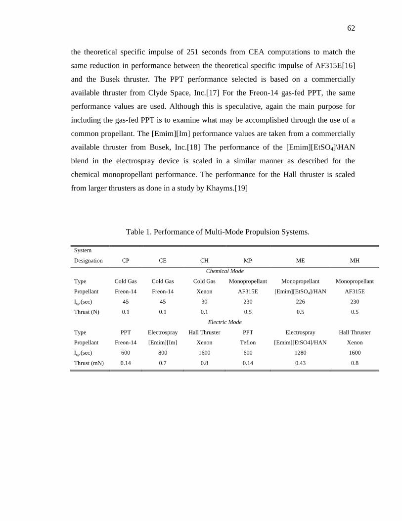
62
the theoretical specific impulse of 251 seconds from CEA computations to match the
same reduction in performance between the theoretical specific impulse of AF315E[16]
and the Busek thruster. The PPT performance selected is based on a commercially
available thruster from Clyde Space, Inc.[17] For the Freon-14 gas-fed PPT, the same
performance values are used. Although this is speculative, again the main purpose for
including the gas-fed PPT is to examine what may be accomplished through the use of a
common propellant. The [Emim][Im] performance values are taken from a commercially
available thruster from Busek, Inc.[18] The performance of the [Emim][EtSO4]\HAN
blend in the electrospray device is scaled in a similar manner as described for the
chemical monopropellant performance. The performance for the Hall thruster is scaled
from larger thrusters as done in a study by Khayms.[19]
Table 1. Performance of Multi-Mode Propulsion Systems.
System
Designation CP CE CH MP ME MH
Chemical Mode
Type Cold Gas Cold Gas Cold Gas Monopropellant Monopropellant Monopropellant
Propellant Freon-14 Freon-14 Xenon AF315E [Emim][EtSO4]/HAN AF315E
Isp (sec) 45 45 30 230 226 230
Thrust (N) 0.1 0.1 0.1 0.5 0.5 0.5
Electric Mode
Type PPT Electrospray Hall Thruster PPT Electrospray Hall Thruster
Propellant Freon-14 [Emim][Im] Xenon Teflon [Emim][EtSO4]/HAN Xenon
Isp (sec) 600 800 1600 600 1280 1600
Thrust (mN) 0.14 0.7 0.8 0.14 0.43 0.8
63
3. MULTI-MODE PROPULSION SYSTEMS ANALYSIS METHODS
Multi-mode propulsion systems enable two primary spacecraft mission benefits:
more efficient planned trajectories and flexible mission scenarios. In either scenario, the
primary goal of the propulsion system design is to accomplish the given objective with as
little mass dedicated to the propulsion system as possible so as to maximize payload
capacity or reduce cost. For multi-mode systems, analysis of spacecraft performance and
mass is complicated by utilizing an additional propulsion system, since it opens a large
design space. And, since this enables flexible mission design scenarios with loosely
defined mission objectives and as yet undetermined requirements, comparing multi-mode
systems for use in such a scenario becomes difficult. Finally, multi-mode systems must
also be assessed in terms of the effectiveness of integrating components, such as
propellants, in terms of gains in mission capability or reduction of propulsion system
mass. The following paragraphs describe the analysis used in this paper to assess and
compare the systems defined previously.
3.1. THE MULTI-MODE ROCKET EQUATION
Spacecraft maneuvers are governed by the Tsiolkovsky rocket equation, shown in
Eq. (10),
0
0
sp
V
I gfme
m
(10)
Multi-mode systems utilize two separate thrusters with separate specific impulses. Thus,
in order to determine the propellant required for a certain maneuver, the chemical and
electric modes must be considered as two separate maneuvers in Eq. (10). If one defines a
parameter for the percentage of the total delta-V to be conducted by electric propulsion,
EP, Eq. (11), one can write the two separate rocket equations, (12) and (13),
64
elecVEP
V
(11)
, 0
(1 )
1
0
sp chem
EP V
I gfme
m
(12)
, 0
1
sp elec
EP V
I gf
f
me
m
(13)
where it is assumed that the chemical burn is conducted first. Practically, for electric
propulsion maneuvers, the actual delta-V required is higher than that of an impulsive
burn. This effect can be accounted for by using a ‘mission planning efficiency’
parameter,[6, 20] Eq. (14),
,elec eff
v
elec
V
V
(14)
Substituting Eq. (14) into Eq. (13) and multiplying Eqs. (12) and (13) and simplifying
yields Eq. (15),
0 , ,
1
0
sp chem v sp elec
V EP EP
g I Ifme
m
(15)
and it can then be easily seen that an effective specific impulse can be defined, which is a
function of the chemical and electric mode specific impulse as well as the EP usage
fraction. The multi-mode specific impulse is then Eq. (16),
1
,
, ,
1sp mm
sp chem v sp elec
EP EPI
I I
(16)
It is also notable that this equation is exactly the same regardless of the order or number
of chemical or electric thrust maneuvers. Finally, since the mission planning efficiency
has been introduced, the delta-V requirement input for Eq. (15) is the delta-V that would
65
be required to complete a given mission with impulsive maneuvers. It is important then to
analyze the mission planning efficiency for each unique continuous thrust maneuver. This
will be discussed further in a later section.
For electric propulsion systems, there exists an optimum specific impulse which
maximizes delivered spacecraft mass under power and time constraints. Oh, et. al.[6]
have used a similar derivation to that above to derive the optimum electric specific
impulse for a combined chemical-electric maneuver, Eq. (17),
, ,
* * *2 2,
2 *2
, , ,
24 1 2 ln 1 0
sp elec sp elecv v sp elec PP P f
sp chem sp chem f sp elec
I I I Pt gPt Pt m
I I g m I
(17)
Examination of this equation shows that for a given power and time constraint, the
optimum electric specific impulse is a function of the desired final spacecraft mass, the
mission planning efficiency, and, interestingly, the chemical specific impulse. It is
important to note that this was derived by optimizing the payload mass delivered per
time; thus, more payload could be delivered if longer transit times are tolerable, or the
mission could be completed in less time at the expense of payload mass. This will be
discussed further in the discussion section.
Eqs. (14) and (17) describe the final spacecraft mass after a propulsive maneuver.
The final spacecraft mass includes both the desired payload and the mass of the
propulsion hardware. Normally, metrics such as specific impulse are sufficient to
describe propulsion system performance. This assumes that the inert mass fraction is
small compared to the propellant mass fraction and is typically the case with launch
vehicles and large spacecraft. However, for microsatellites, the inert mass fraction of the
propulsion system may be half of the entire satellite mass or more. For multi-mode
systems, this could be an even bigger fraction. Thus, specific impulse is not wholly
representative of the propulsion system, but rather a description of how effectively the
onboard propellant is being utilized. To account for the performance losses due to large
propulsion system hardware penalty, the final spacecraft mass fraction is separated into
payload mass fraction and engine mass fraction, Eq. (18),
66
0 0 0
f l em m m
m m m (18)
The engine mass fraction then includes the mass of all propulsion system associated
hardware such as tanks, valves, thrusters, power processing units, and solar arrays. One
of the central design goals for multi-mode propulsion systems, in addition to utilizing a
common propellant, is to make use of common hardware to reduce the mass of the
propulsion system and increase the deliverable payload. In order to gauge this effect, and
provide relevant information in propulsion system conceptual design and selection, a
system integration factor is introduced, Eq. (19),
,int
,
1e
SI
e sep
mf
m (19)
Eq. (19) essentially describes the mass by which a multi-mode propulsion system can be
reduced by using common components, such as tanks and lines, between the two
propulsive modes over a system of the same modes utilizing completely separate
components. Inserting Eqs. (18) and (19) into Eq. (15) gives Eq. (20),
0 , ,
0 0
(1 )sp mm
V
g I e seplSI
mme f
m m
(20)
From this equation, the design goals for multi-mode propulsion systems are clearly
evident. The first term on the right hand side describes the propellant usage, which may
be allocated between two modes, and the second term describes the inert mass penalty,
which can be recovered through designs using common hardware between the two
modes.
67
3.2. CHEMICAL THRUSTER SIZING
The two chemical propellants selected for study are Freon-14 for cold gas and
either [Emim][EtSO4] or AF315E for monopropellant systems as defined in Table 1. For
chemical propellants, relevant parameters for thruster sizing include chamber temperature
and specific heat ratio. The [Emim][EtSO4] propellant combusts to a temperature of 1900
K, a specific heat ratio of 1.22, and a characteristic velocity of 1330 m/s. [9] AF315E
combusts to a chamber temperature of 2300K.[16] The exact composition of AF315E is
not given in the literature, so a specific heat ratio of 1.2 is chosen based on typical values
for combustion products of HAN-based ionic liquid propellants.[9, 21] Given the
combustion characteristics of the propellant, a chemical thruster at a desired thrust level
can be sized by specifying three additional parameters: chamber pressure, nozzle
expansion ratio, and divergence half-cone angle. This study will assume a 300 psi
chamber pressure and a nozzle expansion ratio of 200, which are typical values for on-
orbit thrusters.[14] The nozzle throat area is calculated from Eq. (21),
t
F C
FA
C P
, (21)
where the thrust coefficient is given by Eq. (22),
11
12 21
1 1
e eF
c c
P PC
P P
, (22)
and the pressure ratio can be solved iteratively using Eq. (23),
1 11
11 1 11
2 1
e e
c c
P P
P P
. (23)
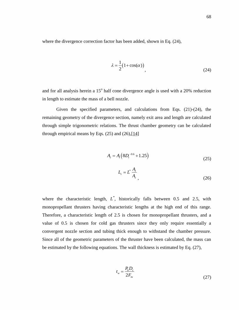
68
where the divergence correction factor has been added, shown in Eq. (24),
1
1 cos( )2
, (24)
and for all analysis herein a 15o half cone divergence angle is used with a 20% reduction
in length to estimate the mass of a bell nozzle.
Given the specified parameters, and calculations from Eqs. (21)-(24), the
remaining geometry of the divergence section, namely exit area and length are calculated
through simple trigonometric relations. The thrust chamber geometry can be calculated
through empirical means by Eqs. (25) and (26),[14]
0.68 1.25c t tA A D (25)
* tc
c
AL L
A
, (26)
where the characteristic length, L*, historically falls between 0.5 and 2.5, with
monopropellant thrusters having characteristic lengths at the high end of this range.
Therefore, a characteristic length of 2.5 is chosen for monopropellant thrusters, and a
value of 0.5 is chosen for cold gas thrusters since they only require essentially a
convergent nozzle section and tubing thick enough to withstand the chamber pressure.
Since all of the geometric parameters of the thruster have been calculated, the mass can
be estimated by the following equations. The wall thickness is estimated by Eq. (27),
2
b cw
tu
P Dt
F
(27)
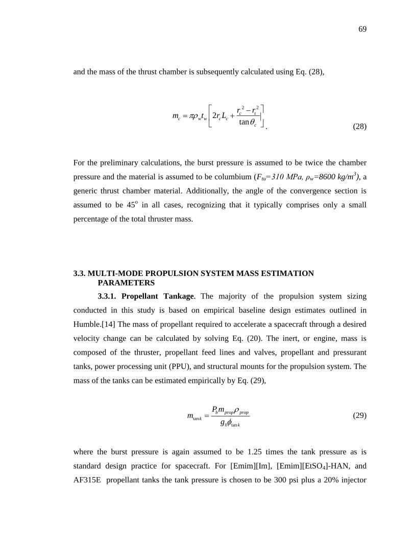
69
and the mass of the thrust chamber is subsequently calculated using Eq. (28),
2 2
2tan
c tc w w c c
c
r rm t r L
. (28)
For the preliminary calculations, the burst pressure is assumed to be twice the chamber
pressure and the material is assumed to be columbium (Ftu=310 MPa, ρw=8600 kg/m3), a
generic thrust chamber material. Additionally, the angle of the convergence section is
assumed to be 45o in all cases, recognizing that it typically comprises only a small
percentage of the total thruster mass.
3.3. MULTI-MODE PROPULSION SYSTEM MASS ESTIMATION
PARAMETERS
3.3.1. Propellant Tankage. The majority of the propulsion system sizing
conducted in this study is based on empirical baseline design estimates outlined in
Humble.[14] The mass of propellant required to accelerate a spacecraft through a desired
velocity change can be calculated by solving Eq. (20). The inert, or engine, mass is
composed of the thruster, propellant feed lines and valves, propellant and pressurant
tanks, power processing unit (PPU), and structural mounts for the propulsion system. The
mass of the tanks can be estimated empirically by Eq. (29),
tan
0 tan
b prop prop
k
k
P mm
g
(29)
where the burst pressure is again assumed to be 1.25 times the tank pressure as is
standard design practice for spacecraft. For [Emim][Im], [Emim][EtSO4]-HAN, and
AF315E propellant tanks the tank pressure is chosen to be 300 psi plus a 20% injector
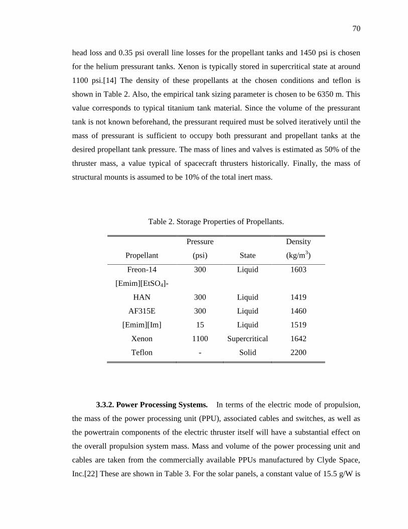
70
head loss and 0.35 psi overall line losses for the propellant tanks and 1450 psi is chosen
for the helium pressurant tanks. Xenon is typically stored in supercritical state at around
1100 psi.[14] The density of these propellants at the chosen conditions and teflon is
shown in Table 2. Also, the empirical tank sizing parameter is chosen to be 6350 m. This
value corresponds to typical titanium tank material. Since the volume of the pressurant
tank is not known beforehand, the pressurant required must be solved iteratively until the
mass of pressurant is sufficient to occupy both pressurant and propellant tanks at the
desired propellant tank pressure. The mass of lines and valves is estimated as 50% of the
thruster mass, a value typical of spacecraft thrusters historically. Finally, the mass of
structural mounts is assumed to be 10% of the total inert mass.
Table 2. Storage Properties of Propellants.
Propellant
Pressure
(psi) State
Density
(kg/m3)
Freon-14 300 Liquid 1603
[Emim][EtSO4]-
HAN 300 Liquid 1419
AF315E 300 Liquid 1460
[Emim][Im] 15 Liquid 1519
Xenon 1100 Supercritical 1642
Teflon - Solid 2200
3.3.2. Power Processing Systems. In terms of the electric mode of propulsion,
the mass of the power processing unit (PPU), associated cables and switches, as well as
the powertrain components of the electric thruster itself will have a substantial effect on
the overall propulsion system mass. Mass and volume of the power processing unit and
cables are taken from the commercially available PPUs manufactured by Clyde Space,
Inc.[22] These are shown in Table 3. For the solar panels, a constant value of 15.5 g/W is
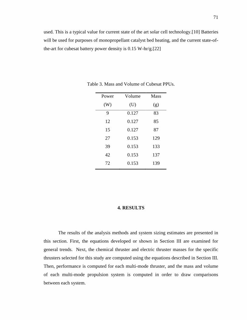
71
used. This is a typical value for current state of the art solar cell technology.[10] Batteries
will be used for purposes of monopropellant catalyst bed heating, and the current state-of-
the-art for cubesat battery power density is 0.15 W-hr/g.[22]
Table 3. Mass and Volume of Cubesat PPUs.
Power
(W)
Volume
(U)
Mass
(g)
9 0.127 83
12 0.127 85
15 0.127 87
27 0.153 129
39 0.153 133
42 0.153 137
72 0.153 139
4. RESULTS
The results of the analysis methods and system sizing estimates are presented in
this section. First, the equations developed or shown in Section III are examined for
general trends. Next, the chemical thruster and electric thruster masses for the specific
thrusters selected for this study are computed using the equations described in Section III.
Then, performance is computed for each multi-mode thruster, and the mass and volume
of each multi-mode propulsion system is computed in order to draw comparisons
between each system.

72
4.1. OPTIMUM SPECIFIC IMPULSE
Perhaps the most interesting portion of Eq. (17) is the observation that the
optimum electric specific impulse for a chemical-electric combined system is dependant
on the chemical mode specific impulse. Oh, et. al.[6] examined the optimum specific
impulse for a single chemical specific impulse, assumed to be 310 seconds for typical
bipropellant propulsion systems for large commercial satellites. It was found that a higher
mission planning efficiency reduces the optimum electric specific impulse. A mission
planning efficiency of unity corresponds to a Hohmann transfer, which is obviously
impossible for a continuous thrust maneuver. It has been found that the mission planning
efficiency does not vary much for earth-orbiting satellites, with values ranging from 0.45
to 0.65, and is typically dependant on the starting and ending orbits and steering profile,
and therefore weakly dependant on the propulsion system technology.[6, 20] A value of
0.5 for the mission planning efficiency will be used for all calculations hereafter.
Since there are many chemical micropropulsion concepts, and also many electric
micropropulsion concepts, it is useful to examine the general trends for optimum electric
specific impulse and the interplay with chemical propulsion system selection in a multi-
mode system. Figure 1 shows the optimum electric specific impulse calculated using Eq.
(17). Figure 1a shows the optimum electric specific impulse at varied energy, the Ptηp
term in Eq. (17), Figure 1b at varied spacecraft mass, and Figure 1c at varied chemical
mode specific impulse. For each figure, when two of the parameters are not varied,
values of 5 MJ, 10 kg, and 250 seconds are chosen for the energy, spacecraft mass, and
chemical specific impulse, respectively. From Figure 1b it is easily seen that the optimum
electric specific impulse does not vary significantly with spacecraft mass, by less than 1%
over the entire range chosen in this case, which is representative of small satellites. The
optimum electric specific impulse does vary somewhat significantly as energy required is
increased. However, for a 30 W, 50% efficiency thruster, the range in Fig 1a represents
0-2 years of thrusting time. If propulsion systems are compared for missions at roughly
the same, but slightly different duration then the optimum electric specific impulse can
also be assumed constant for comparative purposes. Finally, Figure 1c shows the
variation with chemical specific impulse. For a system consisting of a chemical mode

73
thruster of 50 seconds specific impulse, the optimum electric specific impulse is 220
seconds, and for 250 second chemical mode Isp the optimum electric Isp is 1000 seconds.
a)
b)
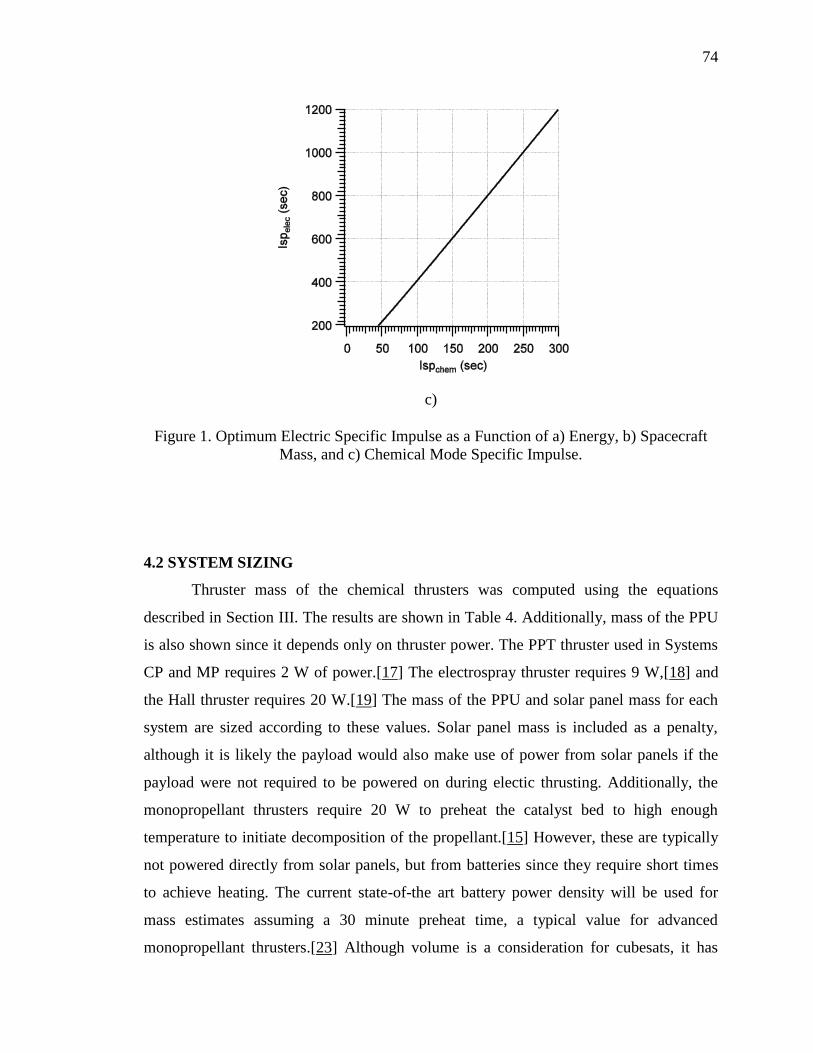
74
c)
Figure 1. Optimum Electric Specific Impulse as a Function of a) Energy, b) Spacecraft
Mass, and c) Chemical Mode Specific Impulse.
4.2 SYSTEM SIZING
Thruster mass of the chemical thrusters was computed using the equations
described in Section III. The results are shown in Table 4. Additionally, mass of the PPU
is also shown since it depends only on thruster power. The PPT thruster used in Systems
CP and MP requires 2 W of power.[17] The electrospray thruster requires 9 W,[18] and
the Hall thruster requires 20 W.[19] The mass of the PPU and solar panel mass for each
system are sized according to these values. Solar panel mass is included as a penalty,
although it is likely the payload would also make use of power from solar panels if the
payload were not required to be powered on during electic thrusting. Additionally, the
monopropellant thrusters require 20 W to preheat the catalyst bed to high enough
temperature to initiate decomposition of the propellant.[15] However, these are typically
not powered directly from solar panels, but from batteries since they require short times
to achieve heating. The current state-of-the art battery power density will be used for
mass estimates assuming a 30 minute preheat time, a typical value for advanced
monopropellant thrusters.[23] Although volume is a consideration for cubesats, it has
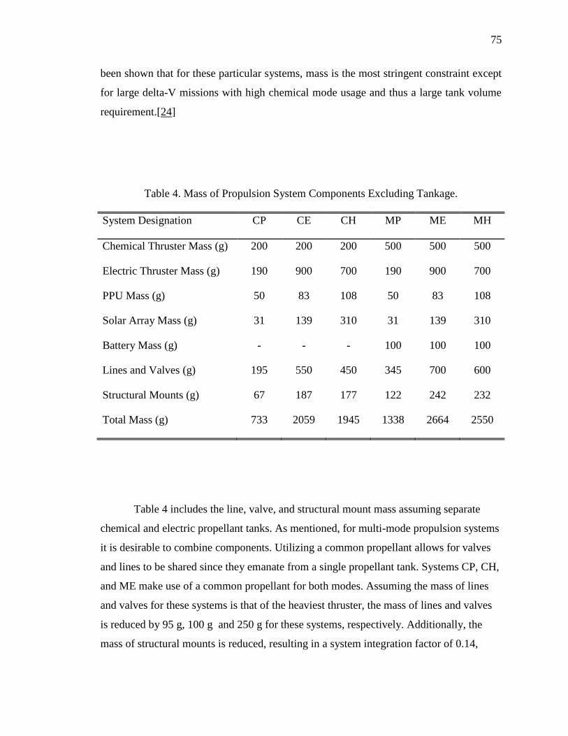
75
been shown that for these particular systems, mass is the most stringent constraint except
for large delta-V missions with high chemical mode usage and thus a large tank volume
requirement.[24]
Table 4. Mass of Propulsion System Components Excluding Tankage.
System Designation CP CE CH MP ME MH
Chemical Thruster Mass (g) 200 200 200 500 500 500
Electric Thruster Mass (g) 190 900 700 190 900 700
PPU Mass (g) 50 83 108 50 83 108
Solar Array Mass (g) 31 139 310 31 139 310
Battery Mass (g) - - - 100 100 100
Lines and Valves (g) 195 550 450 345 700 600
Structural Mounts (g) 67 187 177 122 242 232
Total Mass (g) 733 2059 1945 1338 2664 2550
Table 4 includes the line, valve, and structural mount mass assuming separate
chemical and electric propellant tanks. As mentioned, for multi-mode propulsion systems
it is desirable to combine components. Utilizing a common propellant allows for valves
and lines to be shared since they emanate from a single propellant tank. Systems CP, CH,
and ME make use of a common propellant for both modes. Assuming the mass of lines
and valves for these systems is that of the heaviest thruster, the mass of lines and valves
is reduced by 95 g, 100 g and 250 g for these systems, respectively. Additionally, the
mass of structural mounts is reduced, resulting in a system integration factor of 0.14,
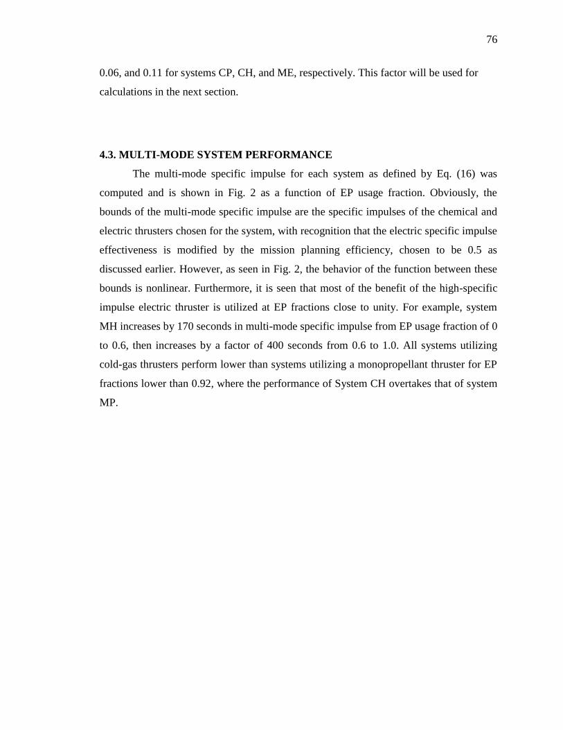
76
0.06, and 0.11 for systems CP, CH, and ME, respectively. This factor will be used for
calculations in the next section.
4.3. MULTI-MODE SYSTEM PERFORMANCE
The multi-mode specific impulse for each system as defined by Eq. (16) was
computed and is shown in Fig. 2 as a function of EP usage fraction. Obviously, the
bounds of the multi-mode specific impulse are the specific impulses of the chemical and
electric thrusters chosen for the system, with recognition that the electric specific impulse
effectiveness is modified by the mission planning efficiency, chosen to be 0.5 as
discussed earlier. However, as seen in Fig. 2, the behavior of the function between these
bounds is nonlinear. Furthermore, it is seen that most of the benefit of the high-specific
impulse electric thruster is utilized at EP fractions close to unity. For example, system
MH increases by 170 seconds in multi-mode specific impulse from EP usage fraction of 0
to 0.6, then increases by a factor of 400 seconds from 0.6 to 1.0. All systems utilizing
cold-gas thrusters perform lower than systems utilizing a monopropellant thruster for EP
fractions lower than 0.92, where the performance of System CH overtakes that of system
MP.
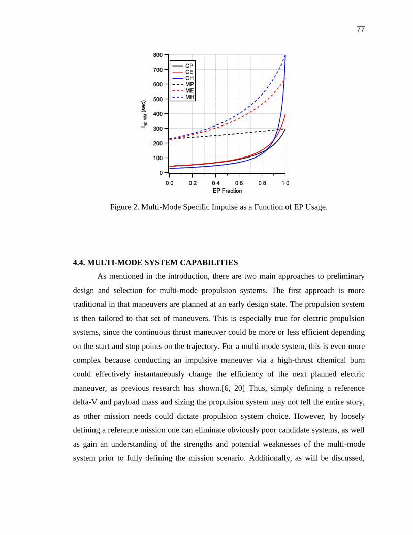
77
Figure 2. Multi-Mode Specific Impulse as a Function of EP Usage.
4.4. MULTI-MODE SYSTEM CAPABILITIES
As mentioned in the introduction, there are two main approaches to preliminary
design and selection for multi-mode propulsion systems. The first approach is more
traditional in that maneuvers are planned at an early design state. The propulsion system
is then tailored to that set of maneuvers. This is especially true for electric propulsion
systems, since the continuous thrust maneuver could be more or less efficient depending
on the start and stop points on the trajectory. For a multi-mode system, this is even more
complex because conducting an impulsive maneuver via a high-thrust chemical burn
could effectively instantaneously change the efficiency of the next planned electric
maneuver, as previous research has shown.[6, 20] Thus, simply defining a reference
delta-V and payload mass and sizing the propulsion system may not tell the entire story,
as other mission needs could dictate propulsion system choice. However, by loosely
defining a reference mission one can eliminate obviously poor candidate systems, as well
as gain an understanding of the strengths and potential weaknesses of the multi-mode
system prior to fully defining the mission scenario. Additionally, as will be discussed,
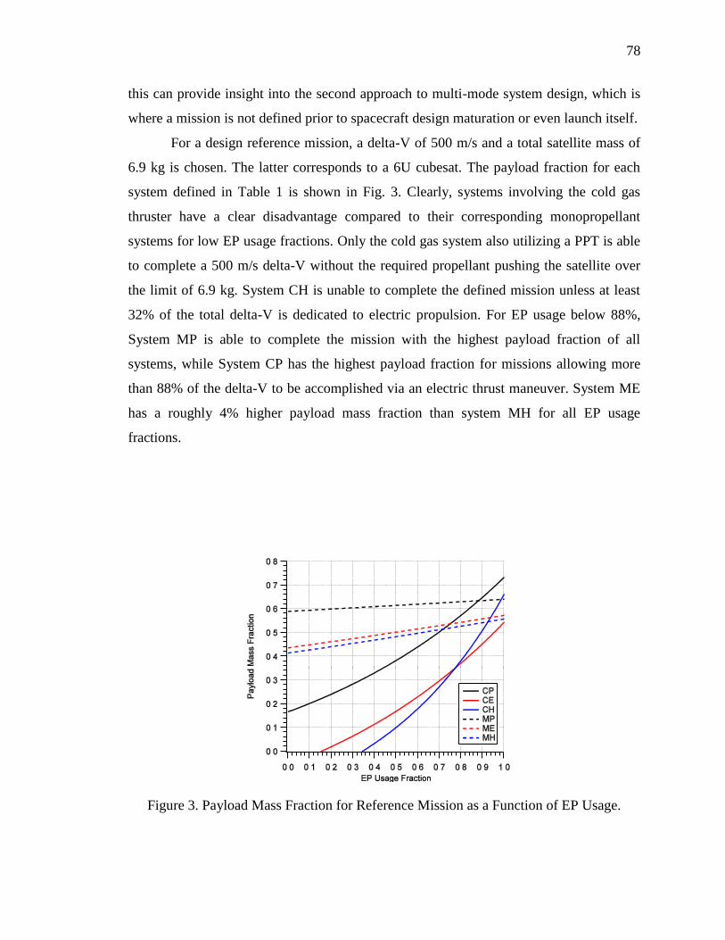
78
this can provide insight into the second approach to multi-mode system design, which is
where a mission is not defined prior to spacecraft design maturation or even launch itself.
For a design reference mission, a delta-V of 500 m/s and a total satellite mass of
6.9 kg is chosen. The latter corresponds to a 6U cubesat. The payload fraction for each
system defined in Table 1 is shown in Fig. 3. Clearly, systems involving the cold gas
thruster have a clear disadvantage compared to their corresponding monopropellant
systems for low EP usage fractions. Only the cold gas system also utilizing a PPT is able
to complete a 500 m/s delta-V without the required propellant pushing the satellite over
the limit of 6.9 kg. System CH is unable to complete the defined mission unless at least
32% of the total delta-V is dedicated to electric propulsion. For EP usage below 88%,
System MP is able to complete the mission with the highest payload fraction of all
systems, while System CP has the highest payload fraction for missions allowing more
than 88% of the delta-V to be accomplished via an electric thrust maneuver. System ME
has a roughly 4% higher payload mass fraction than system MH for all EP usage
fractions.
Figure 3. Payload Mass Fraction for Reference Mission as a Function of EP Usage.

79
An additional consideration important in electric propulsion systems, and thus
multi-mode propulsion systems also, is the required time to expel all propellant carried
onboard the spacecraft. This can serve as a comparison for how long the mission will take
with a given propulsion system. However, this may not describe the entire scenario as the
length between burns is not defined. Furthermore, the selection of burn type and duration
could play a significant role such that the time of unpowered flight is significantly larger
than the burn duration in one case, but not in another. So, while simply comparing burn
duration required of a propulsion system does not come close to describing the actual
mission scenario, it does at minimum serve as a lower bound. The burn duration for the
reference mission described previously is shown in Fig. 4. For all three electric
propulsion systems, the burn duration is longer when using a monopropellant thruster
compared to a cold gas thruster. Systems using a PPT in the electric mode require the
longest burn durations, while the cold gas system involving the Hall thruster has the
lowest overall burn times, requiring only about 20% of the total time required to perform
the 500 m/s delta-V compared to the PPT systems. Systems ME and MH appear identical
in the graph, however closer examination reveals system ME actually requires roughly
1% shorter burn times than System MH.
Figure 4. Burn Time for Reference Mission as a Function of EP Usage.
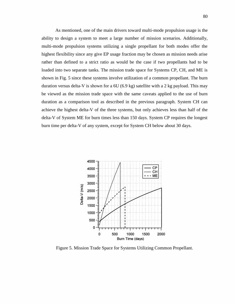
80
As mentioned, one of the main drivers toward multi-mode propulsion usage is the
ability to design a system to meet a large number of mission scenarios. Additionally,
multi-mode propulsion systems utilizing a single propellant for both modes offer the
highest flexibility since any give EP usage fraction may be chosen as mission needs arise
rather than defined to a strict ratio as would be the case if two propellants had to be
loaded into two separate tanks. The mission trade space for Systems CP, CH, and ME is
shown in Fig. 5 since these systems involve utilization of a common propellant. The burn
duration versus delta-V is shown for a 6U (6.9 kg) satellite with a 2 kg payload. This may
be viewed as the mission trade space with the same caveats applied to the use of burn
duration as a comparison tool as described in the previous paragraph. System CH can
achieve the highest delta-V of the three systems, but only achieves less than half of the
delta-V of System ME for burn times less than 150 days. System CP requires the longest
burn time per delta-V of any system, except for System CH below about 30 days.
Figure 5. Mission Trade Space for Systems Utilizing Common Propellant.
81
To further illustrate the gains in mission flexibility by using a common propellant
in a multi-mode propulsion system, System ME is compared to a system consisting of the
same thruster modes, but with separate AF315E and [Emim][Im] propellants for the
chemical mode and electric mode, respectively. The performance and mass estimates for
these thrusters are the same as given in Section II and III, except here the specific
impulse of the electric mode is scaled up to 1280 seconds. Note that this could be
accomplished through addition of accelerator grids with additional mass penalty. For this
analysis, however no additional mass penalty is applied. The mission trade space for
these two systems is shown in Fig. 6 for a 180 kg satellite with a 65 kg payload. The solid
black line represents System ME, which uses a common propellant, and the colored lines
represent the system using separate propellants. For the system using separate propellants
it is necessary to define the mission trade space by choosing a single allocation of
propellant mass. Stated differently, a mission designer may only allocate propellant usage
before the mission begins and may only select one of the colored curves. Anything except
for the peak of the colored curves is therefore a mission that does not result in 100%
propellant utilization. On the other hand, if a common propellant is used, the entire area
under the black curve is available for mission applications, even after launch, and 100%
propellant utilization is achieved for any mission chosen on the black curve. Also notable
is that the combined system has a higher delta-V at a given burn duration for all missions
except the 100% chemical and 100% electric missions in which the mass of the opposite
mode thruster and associated hardware has been removed. This is due to the use of shared
hardware in the common propellant system.

82
Figure 6. Mission Design Trade Space for Multi-mode Ionic Liquid Propulsion Systems.
5. DISCUSSION
Clearly, from the results, missions requiring a majority of the total delta-V to be
performed through quick, impulsive chemical maneuvers, the specific impulse of the
chemical mode is the most important consideration, since from Fig. 3 all of the
monopropellant systems have a higher payload mass fraction for EP usage below 88% of
the total delta-V. Of the monopropellant systems, System MP has the highest payload
fraction, but requires a significant burn duration. Despite having a higher thruster and
powertrain mass than System MH, System ME has a higher payload mass fraction for the
reference mission while still requiring shorter burn times. This is due to both the fact that
System ME has a reduced inert mass due to shared lines and vales, but also somewhat
due to the electric mode specific impulse being closer to optimum for the chemical
monopropellant mode specific impulse, Fig. 1c, than the hall thruster.
In terms of required burn duration to expend all onboard propellant, the PPT
systems have the longest burn times. This is due directly to the fact that they have the
83
lowest electric mode thrust of any propulsion system considered in this study. The thrust
of the electric mode effectively dictates the burn duration of the entire multi-mode
propulsion system since any low-thrust maneuver utilizing electric propulsion takes
significantly longer than a chemical burn even to expel 100% of the propellant. Thus,
systems involving the higher-power thrusters could be advantageous for multi-mode
systems where spacecraft lifetime or mission lifetime is a critical factor.
For spacecraft designs involving flexible mission scenarios, the system with the
cold gas thruster combined with the hall thruster could be the most advantageous since it
offers a relatively high delta-V capability in a short amount of time for a given payload
mass and total spacecraft mass. However, for most earth-orbiting missions typically
lasting shorter than 150 days, the monopropellant/electrospray system is the most
advantageous. Furthermore, for flexible mission design, it is crucial to make use of a
common propellant between modes as from Fig. 6 the mission design space not only
encompasses the design space of all possible propellant budget allocations using separate
propellants, but exceeds the performance except for missions involving 100% chemical
or 100% electric maneuvers due to the use of shared hardware reducing the propulsion
system inert mass.
As mentioned in the results section, the shape of the multi-mode specific impulse
function is exponential, with most of the specific impulse benefit of the electric system
being realized through high values of EP usage. In a flexible mission design scenario
such as that defined in the results section where the only constraints are payload mass and
total spacecraft mass, limiting propulsion system inert mass is more important than high
specific impulse in either chemical or electric mode. Or stated differently, reducing inert
mass of the propulsion system allows for a greater fraction of the onboard mass to be
propellant. The fact that specific impulse grows at a rate greater than linear according to
the multi-mode specific impulse function means that more available propellant will result
in an exponentially growing delta-V availability as propulsion system inert mass is
reduced. It is therefore highly advantageous to reduce propulsion system inert mass as
much as possible through hardware integration or careful selection of components.
84
Finally, the concept of the optimum electric mode specific impulse must be
revisited. As discussed in the results section the optimum electric specific impulse
depends on the chemical mode specific impulse. The optimum occurs because there is a
trade-off between the payload mass fraction gain by increased specific impulse and
increased time required by decreased power. [6] Under a fixed mission duration, for a
large electric specific impulse, the electric propulsion system makes efficient use of the
propellant, but would deliver a smaller fraction of the total delta-V. The chemical thruster
would then provide the remaining delta-V at a defined ratio in order to meet the mission
time requirements. Conversely, if the chemical thruster specific impulse is low, it would
be desirable to use less of the chemical thruster. Thus, as the chemical mode specific
impulse decreases, it is desirable to increase the electric mode thrust at the expense of
specific impulse.
For multi-mode propulsion system design it is desirable to select electric
propulsion technology near this optimum. However, this only describes performance
from a propellant usage standpoint. If an electric technology is sufficiently low in mass,
or it can be integrated partially or fully with the chemical mode, it may result in a higher
performance system even if the electric specific impulse is far from optimum.
6. CONCLUSIONS
Multi-mode spacecraft propulsion systems involving separate chemical and
electric thrusters were compared and analyzed in terms of mission capability and overall
system sizing. Propulsion systems involving chemical monopropellant thrusters generally
outperformed their cold-gas counter parts in terms of both payload mass fraction and
propulsion system volume required to perform a 500 m/s delta-V with a 6U scale
spacecfraft (6.9 kg). The thrust of the electric mode effectively determines minimum burn
duration directly, and as such the systems utilizing the PPT had the highest burn
durations since they also had the lowest thrust of all electric propulsion systems

85
considered in this study. For flexible propulsion system design, a multi-mode system
utilizing a common propellant is the most important consideration, followed by reduction
of propulsion system inert mass through the use of common hardware. There exists an
optimum electric specific impulse for a unique chemical specific impulse selection. It is
ideal then, to pair electric technology near this optimum specific impulse for a given
chemical thruster technology.
REFERENCES
[1] S. P. Berg, and Rovey, J. L., "Assessment of High-Power Electric Multi-Mode
Spacecraft Propulsion Concepts," 33rd International Electric Propulsion Conference,
IEPC-2013-308, 2013.
[2] J. M. Haas, and Holmes, M. R., "Multi-Mode Propulsion System for the Expansion of
Small Satellite Capabilities," NATO, Rept. MP-AVT-171-05, 2010.
[3] T. Rexius, and Holmes, M., "Mission Capability Gains from Multi-Mode Propulsion
Thrust Profile Variations for a Plane Change Maneuver," AIAA Modeling and
Simulation Technologies Conference, AIAA Paper 2011-6431, 2011.
[4] L. M. Mailhe, Heister, S. D., "Design of a Hybrid Chemical/Electric Propulsion
Orbital Transfer Vehicle," Journal of Spacecraft and Rockets, Vol. 39, No. 1, 2002,
pp. 131-139.
[5] C. A. Kluever, "Spacecraft Optimization with Combined Chemical-Electric
Propulsion," Journal of Spacecraft and Rockets, Vol. 32, No. 2, 1994, pp. 378-380.
[6] D. Y. Oh, Randolph, T., Kimbrel, S., and Martinez-Sanchez, M., "End-toEnd
Optimization of Chemical-Electric Orbit Raising Missions," Journal of Spacecraft
and Rockets, Vol. 41, No. 5, 2004, pp. 831-839.
[7] J. H. Gilland, "Synergistic Use of High and Low Thrust Propulsion Systems for
Piloted Missions to Mars," AIAA Paper 1991-2346, 1991.
86
[8] B. R. a. R. Donius, J. L., "Ionic Liquid Dual-Mode Spacecraft Propulsion
Assessment," Journal of Spacecraft and Rockets, Vol. 48, No. 1, 2011, pp. 110-123.
[9] S. P. Berg, and Rovey, J. L., "Assessment of Imidazole-Based Energetic Ionic Liquids
as Dual-Mode Spacecraft Propellants," Journal of Propulsion and Power, Vol. 29, No.
2, 2013, pp. 339-351.
[10] J. R. Wertz, Everett, D. F., and Puschell, J. J., Space Mission Engineering: The New
SMAD, Microcosm Press, Hawthorne, CA, 2011.
[11] K. Masuyama, and Lozano, P. C., "Bimodal Propulsion System Using Ionic Liquid
Propellant for Pico- and Nano-satellite Applications," 49th AIAA/ASME/SAE/ASEE
Joint Propulsion Conference, AIAA Paper 2013-3962, 2013.
[12] S. P. Berg, and Rovey, J. L., "Decomposition of Monopropellant Blends of
Hydroxylammonium Nitrate and Imidazole-Based Ionic Liquid Fuels," Journal of
Propulsion and Power, Vol. 29, No. 1, 2013, pp. 125-135.
[13] G. P. Sutton, and Biblarz, O., Rocket Propulsion Elements, 7th, Wiley, New York,
2001.
[14] R. W. Humble, Henry, G. N., and Larson, W. J., Space Propulsion Analysis and
Design, McGraw-Hill, 1995.
[15] "Green Monopropellant Thrusters." Busek, Inc.
[16] T. Hawkins, Brand, A., McKay, M., Drake, G., and Ismail, I. M. K.,
"Characterization of Reduced Toxicity, High Performance Monopropellants at the U.
S. Air Force Research Laboratory," Air Force Research Laboratory, Rept. AFRL-PR-
ED-TP-2001-137, 2001.
[17] "Cubesat uPulse Plasma Thruster." Clyde Space, Inc.
[18] "Busek Electrospray Thrusters." Busek, Inc.
[19] V. Khayms, "Advanced Propulsion for Microsatellites," PhD Thesis, Aeronautics &
Astronautics, Massachusetts Institute of Technology, 2000.
87
[20] C. A. Kluever, "Optimal Geostationary Orbit Transfers Using Onboard Chemical-
Electric Propulsion," Journal of Spacecraft and Rockets, Vol. 49, No. 6, 2012, pp.
1174-1182.
[21] D. Zube, Wucherer, E., and Reed, B., "Evaluation of HAN-Based Propellant
Blends," 39th AIAA/ASME/SAE/ASEE Joint Propulsion Conference & Exhibit,
AIAA Paper 2003-4643, 2003.
[22] "Cubesat Electrical Power Systems." Clyde Space, Inc.
[23] K. Anflo, Persson, S., Thormahlen, P., Bergman, G., and Hasanof, T., "Flight
Demonstration of ADN-Based Propulsion System on the PRISMA Satellite," 42nd
AIAA/ASME/SAE/ASEE Joint Propulsion Conference & Exhibit, AIAA Paper 2006-
5212, 2006.
[24] S. P. Berg, and Rovey, J. L., "Assessment of Multi-Mode Spacecraft
Micropropulsion Systems," 50th AIAA/ASME/SAE/ASEE Joint Propulsion
Conference, AIAA Paper 2014-3758, 2014.
88
III. Decomposition of a Double Salt Ionic Liquid Monopropellant on Heated
Metallic Surfaces
Steven P. Berg and Joshua L. Rovey
Missouri University of Science and Technology, Rolla, Missouri, 65409
ABSTRACT
A monopropellant consisting of 59% hydroxylammonium nitrate and 41% 1-
ethyl-3-methylimidazolium ethyl sulfate is tested for decomposition on heated platinum,
rhenium, and titanium surfaces. It was found that the propellant decomposes at 165 oC on
titanium, which is the decomposition temperature of HAN. The onset temperature for
decomposition on platinum was 85 oC and on rhenium it was 125
oC. This suggests that
platinum and rhenium act as catalysts for the decomposition of the monopropellant. From
the experimental data, Arrhenius-type reaction rate parameters were calculated. The
activation energy for platinum was 3 times less than that of titanium suggesting it could
be a prime choice for catalyst material in further thruster development.
NOMECLATURE
A = activity coefficient, [1/sec]
Cp,i = specific heat of species i, [J/kg-K]
E = activation energy, [J]
k’ = reaction rate coefficient, [1/sec]
kB = Boltzmann constant, [m2-kg/sec
2-K]
Ni = number of moles of species i, [mol]
89
Q = heat transfer rate, [W]
"Q = heat flux, [W/mm2]
EQ = heat transfer rate due to electrical heating, [W]
rA = reaction rate, [mol/m-sec]
T = temperature, [K]
blankT = heating rate on blank surface, [K/s]
ET = electrical heating rate, [K/s]
sT = self heating rate, [K/s]
Tm = melting temperature, [K]
t = time, [sec]
V = volume, [m3]
ΔHRx = heat of reaction, [J/mol]
ρ = resistivity, [Ω-m]
κ = thermal conductivity, [W/m-K]
1. INTRODUCTION
Multi-mode spacecraft propulsion is the use of two or more propulsive devices on
a spacecraft, specifically making use of a high-thrust, usually chemical, mode and a high-
specific impulse, usually electric mode. This can be beneficial in two primary ways. One
way a multi-mode propulsion system can be beneficial is by designing a mission such
that the high-thrust and high-specific impulse maneuvers are conducted in such a way
that it provides a more optimum trajectory over a single chemical or single electric
maneuver.[1-4] The second is to increase the mission flexibility of a single spacecraft
architechture in that both high-thrust and high-specific impulse maneuvers are available
to mission designers at will, perhaps even allowing for drastic changes in the mission
90
plan while on-orbit or with a relatively short turnaround from concept to launch.[5-9] For
the second method, it is extremely beneficial to utilize a common propellant for both
modes as this provides the highest flexibility in terms of mission design choices. Two
propellants have been developed which may function and theoretically perform well in
both a chemical monopropellant and electric electrospray mode.[10] These propellants,
based on mixtures of ionic liquids [Emim][EtSO4] and [Bmim][NO3] with ionic liquid
oxidizer hydroxylammonium nitrate (HAN), have been previously synthesized and
assessed for thermal and catalytic decomposition in a microreactor.[11] This paper
presents results of further experiments to characterize the decomposition of the
[Emim][EtSO4]-HAN monopropellant, specifically on catalytic surfaces relevant to
application in a microtube thruster.[12-14] The electrospray capabilities of the
propellants have been investigated previously.[15]
Hydrazine has been the monopropellant of choice for spacecraft and gas
generators because it is storable and easily decomposed to give good combustion
properties [16]. However, hydrazine is also highly toxic and recent efforts have been
aimed at replacing hydrazine with a high-performance, non-toxic monopropellant. Many
of these efforts have focused on energetic ionic liquids, which are essentially molten salts
capable of rapid decomposition into gaseous products. The energetic salts
hydroxylammonium nitrate (HAN), ammonium dinitramide (ADN), and hydrazinium
nitroformate (HNF) have received attention for this purpose.[16-20] All of these salts
have melting points above room temperature, and it is therefore necessary to use them in
an aqueous solution to create a storable liquid propellant. Typically, these are also mixed
with a compatible fuel component to provide improved performance. The main limitation
to the development of these as monopropellants has been excessive combustion
temperatures, but recent efforts in materials and thermal management have mitigated
some of these issues and flight tests have been conducted or are scheduled.[20-22] These
propellants, while performing well for chemical propulsion, fundamentally will not
perform well in an electrospray thruster; therefore, for a proposed multi-mode
monopropellant/electrospray system, novel system-specific propellants will be needed
and the first generation has been synthesized.[10, 11]
91
Recent efforts have placed a greater emphasis on smaller spacecraft, specifically
microsatellites (10-100 kg) and nanosatellites (1-10 kg), including the subset of
cubesats.[23] Many different types of thrusters have been proposed to meet the stringent
mass and volume requirements placed on spacecraft of this type. Electrospray, in
particular, may be well suited for micropropulsion, and has been selected for these types
of applications.[24-26] Many types of thrusters have been proposed for chemical
propulsion for small spacecraft. One type is the chemical microtube.[12-14] This type of
thruster is simply a heated tube of diameter ~1 mm or less that may or may not consist of
a catalytic surface material. Additionally, from a multi-mode system standpoint, there is
no fundamental reason why this geometry could not be shared with the electrospray mode
as capillary type emitters can be roughly the same diameter tube.[15, 27]
Due to the stringent mass, volume, and power requirements on micropropulsion
systems, the required preheat temperature and overall length of the tube to achieve peak
performance is important. However, in order to assess these requirements, and in turn
design an experimental thruster, basic properties of the propellant decomposition and
burning behavior must be determined. This paper presents results on the experimental
determination and assessment of the decomposition characteristics of the
[Emim][EtSO4]-HAN propellant on various catalytic surfaces through the use of a batch
reactor. These measurements, taken together, can be used directly or compared to
existing models of HAN propellant decomposition to aid the design of a catalytic
microtube thruster. Section II will describe the setup of the experiment, Section III will
present the results of the experiments, Section IV will discuss the results including
relevant development or selection of decomposition model parameters, and Section V
presents the conclusions of this study.
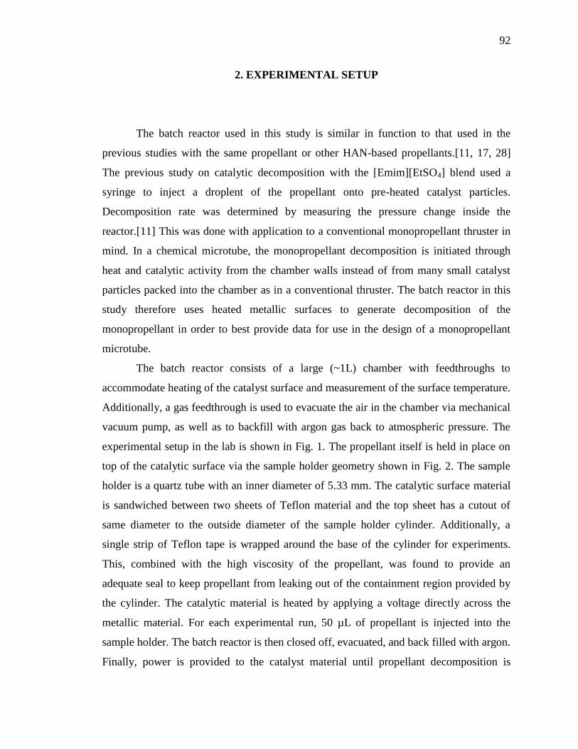
92
2. EXPERIMENTAL SETUP
The batch reactor used in this study is similar in function to that used in the
previous studies with the same propellant or other HAN-based propellants.[11, 17, 28]
The previous study on catalytic decomposition with the [Emim][EtSO4] blend used a
syringe to inject a droplent of the propellant onto pre-heated catalyst particles.
Decomposition rate was determined by measuring the pressure change inside the
reactor.[11] This was done with application to a conventional monopropellant thruster in
mind. In a chemical microtube, the monopropellant decomposition is initiated through
heat and catalytic activity from the chamber walls instead of from many small catalyst
particles packed into the chamber as in a conventional thruster. The batch reactor in this
study therefore uses heated metallic surfaces to generate decomposition of the
monopropellant in order to best provide data for use in the design of a monopropellant
microtube.
The batch reactor consists of a large (~1L) chamber with feedthroughs to
accommodate heating of the catalyst surface and measurement of the surface temperature.
Additionally, a gas feedthrough is used to evacuate the air in the chamber via mechanical
vacuum pump, as well as to backfill with argon gas back to atmospheric pressure. The
experimental setup in the lab is shown in Fig. 1. The propellant itself is held in place on
top of the catalytic surface via the sample holder geometry shown in Fig. 2. The sample
holder is a quartz tube with an inner diameter of 5.33 mm. The catalytic surface material
is sandwiched between two sheets of Teflon material and the top sheet has a cutout of
same diameter to the outside diameter of the sample holder cylinder. Additionally, a
single strip of Teflon tape is wrapped around the base of the cylinder for experiments.
This, combined with the high viscosity of the propellant, was found to provide an
adequate seal to keep propellant from leaking out of the containment region provided by
the cylinder. The catalytic material is heated by applying a voltage directly across the
metallic material. For each experimental run, 50 µL of propellant is injected into the
sample holder. The batch reactor is then closed off, evacuated, and back filled with argon.
Finally, power is provided to the catalyst material until propellant decomposition is
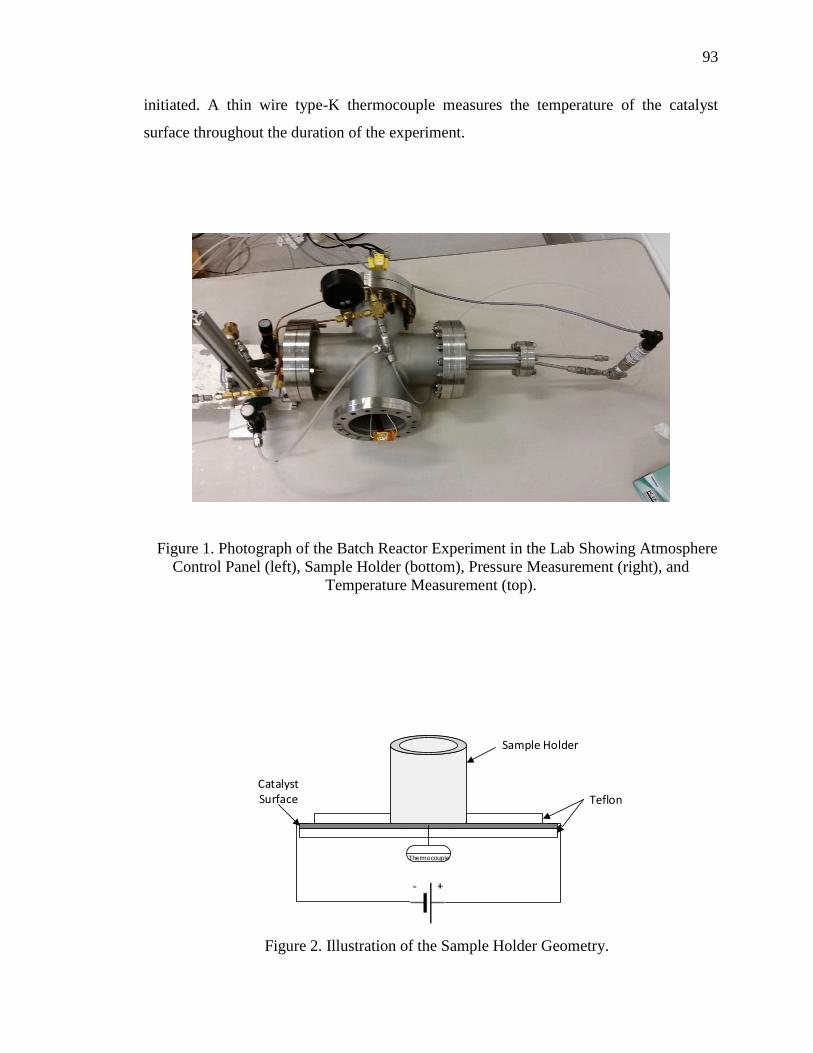
93
initiated. A thin wire type-K thermocouple measures the temperature of the catalyst
surface throughout the duration of the experiment.
Figure 1. Photograph of the Batch Reactor Experiment in the Lab Showing Atmosphere
Control Panel (left), Sample Holder (bottom), Pressure Measurement (right), and
Temperature Measurement (top).
Thermocouple
Teflon
Sample Holder
Catalyst Surface
Figure 2. Illustration of the Sample Holder Geometry.

94
As mentioned, the propellant used in this study is a blend of hydroxylammonium
nitrate (HAN) and 1-ethyl-3-methylimidazolium ethyl sulfate ([Emim][EtSO4])
consisting of 59% oxidizer and 41% fuel by mass. The synthesis procedure is described
in detail in the previous studies.[11, 15] Three catalyst materials are selected for this
investigation: titanium, platinum, and rhenium. Rhenium was found from the previous
study to be a good candidate catalyst material.[11] Platinum was the material selected for
the previous microtube thruster experiments[12-14] and is also a candidate for HAN
propellant catalyst applications.[28] Titanium is selected for this study to provide a
measure of thermal decomposition absent catalytic activity since it it known to be
compatible with HAN propellants for long term storage.[29] The properties relevant to
this study for each material are given in Table 1. For the experiment, a 25 mm x 8 mm
strip of 0.025 mm thick material is used for platinum and rhenium. For titanium the
dimensions are the same except for the thickness, which is 0.05 mm.
Table 1. Thermal and Electrical Properties of Catalyst Materials Used in This Study.
ρ [Ω-m] x 10-7
κ [W/m-K] Tm [K]
Platinum 1.04 71.6 1968
Rhenium 1.85 71.0 3382
Titanium 4.27 20.8 1868
3. RESULTS
Results from the batch reactor experiment described in the previous section are
presented here. All decomposition experiments are conducted in a 15 psia argon internal
atmosphere and with 50 µL of propellant. For comparison, an 80% HAN/water blend and
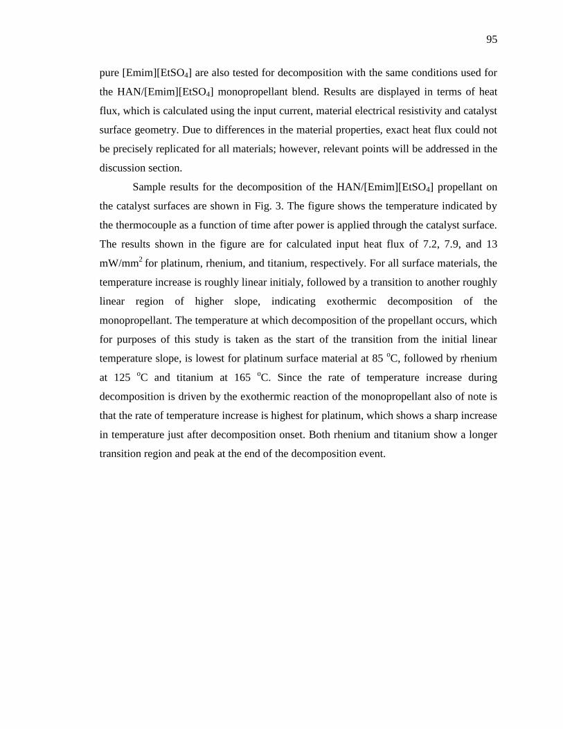
95
pure [Emim][EtSO4] are also tested for decomposition with the same conditions used for
the HAN/[Emim][EtSO4] monopropellant blend. Results are displayed in terms of heat
flux, which is calculated using the input current, material electrical resistivity and catalyst
surface geometry. Due to differences in the material properties, exact heat flux could not
be precisely replicated for all materials; however, relevant points will be addressed in the
discussion section.
Sample results for the decomposition of the HAN/[Emim][EtSO4] propellant on
the catalyst surfaces are shown in Fig. 3. The figure shows the temperature indicated by
the thermocouple as a function of time after power is applied through the catalyst surface.
The results shown in the figure are for calculated input heat flux of 7.2, 7.9, and 13
mW/mm2
for platinum, rhenium, and titanium, respectively. For all surface materials, the
temperature increase is roughly linear initialy, followed by a transition to another roughly
linear region of higher slope, indicating exothermic decomposition of the
monopropellant. The temperature at which decomposition of the propellant occurs, which
for purposes of this study is taken as the start of the transition from the initial linear
temperature slope, is lowest for platinum surface material at 85 oC, followed by rhenium
at 125 oC and titanium at 165
oC. Since the rate of temperature increase during
decomposition is driven by the exothermic reaction of the monopropellant also of note is
that the rate of temperature increase is highest for platinum, which shows a sharp increase
in temperature just after decomposition onset. Both rhenium and titanium show a longer
transition region and peak at the end of the decomposition event.
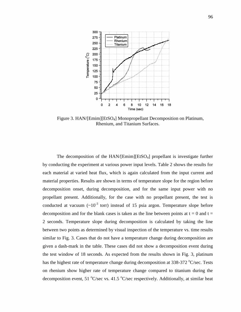
96
Figure 3. HAN/[Emim][EtSO4] Monopropellant Decomposition on Platinum,
Rhenium, and Titanium Surfaces.
The decomposition of the HAN/[Emim][EtSO4] propellant is investigate further
by conducting the experiment at various power input levels. Table 2 shows the results for
each material at varied heat flux, which is again calculated from the input current and
material properties. Results are shown in terms of temperature slope for the region before
decomposition onset, during decomposition, and for the same input power with no
propellant present. Additionally, for the case with no propellant present, the test is
conducted at vacuum (~10-3
torr) instead of 15 psia argon. Temperature slope before
decomposition and for the blank cases is taken as the line between points at t = 0 and t =
2 seconds. Temperature slope during decomposition is calculated by taking the line
between two points as determined by visual inspection of the temperature vs. time results
similar to Fig. 3. Cases that do not have a temperature change during decomposition are
given a dash-mark in the table. These cases did not show a decomposition event during
the test window of 18 seconds. As expected from the results shown in Fig. 3, platinum
has the highest rate of temperature change during decomposition at 338-372 oC/sec. Tests
on rhenium show higher rate of temperature change compared to titanium during the
decomposition event, 51 oC/sec vs. 41.5
oC/sec respectively. Additionally, at similar heat
97
flux, the platinum cases have a higher temperature slope before decomposition compared
to both rhenium and titanium. For example, the temperature slope for heat flux of 3.2
mW/mm2 is 7.5
oC/sec for platinum and 6.0
oC/sec for rhenium; and, the temperature
slope is 10 oC/sec for platinum at 5 mW/mm
2 heat flux and 6.7
oC/sec at 5.4 mW/mm
2 for
titanium. This trend is true for all cases tested. Tests on rhenium also show a slightly
higher rate of temperature change prior to decomposition onset compared to titanium, for
example 9.3 oC/sec at 4.3 mW/mm
2 on rhenium versus 8.5
oC/sec at 7 mW/mm
2 on
titanium.
98
Table 2. Rate of Temperature Change Before and During Decomposition Events for
Each Catalyst Surface at Various Input Power.
"Q
(mW/mm2)
ET
(oC/s) ST (
oC/s)
blankT (oC/s)
Platinum
3.2 7.5 - 10.0
4.4 9.5 354 17.7
5.0 10.0 363 27.0
6.0 15.0 338 31.7
7.2 21.5 372 37.5
Rhenium
1.4 3.3 - 6.0
3.2 6.0 - 11.0
4.3 9.3 - 18.5
5.7 11.7 52 34.7
7.9 13.5 50 44.0
Titanium
5.4 6.7 - 23.3
7.0 8.5 - 35
8.8 9.7 40 47.7
10.9 10.0 41 52.5
13.0 11.0 43 60.3
More information about the propellant decomposition process may be obtained by
observing the decomposition of the constituent fuel and oxidizer. As mentioned, an 80%
HAN by mass HAN/water solution and pure [Emim][EtSO4] are tested for
decomposition. Results on platinum at heat flux of 7.2 mW/mm2 are shown in Fig. 4.
99
From the figure, the decomposition of HAN/Water is virtually the same as that of the
HAN/[Emim][EtSO4] monopropellant blend. The temperature rate of change is the same
value of 21.5 oC/sec, the onset temperature is 85
oC, and the temperature slope during
decomposition is slightly lower for HAN/Water at 283 oC/sec. The behavior of
temperature data after the decomposition event for HAN/Water is noticeably erratic; this
will be discussed in the next section. Pure [Emim][EtSO4] does show an exothermic
decomposition peak, which has been observed qualitatively before during spot plate
tests.[11] This occurs at roughly 140 oC on platinum, well above the decomposition onset
of 85 oC for HAN/Water and HAN/[Emim][EtSO4] blend.
Figure 4. Decomposition of HAN/[Emim][EtSO4] Monopropellant and Constituent
Fuel and Oxidizer on Platinum.
100
4. DISCUSSION
Results from the preceding section are discussed, with particular attention paid to
developing insights for the development of a microtube thruster. However, there is no
reason why the results could not also be used, at minimum qualitatively, for catalyst
development, particularly monolith catalysts. The results and trends seen in the previous
section will first be discussed, followed by elucidation of these results into Arrhenius
type reaction rate data.
4.1. DISCUSSION OF EXPERIMENTAL RESUTLS
The most significant result of the experiment is the fact that the lowest onset
temperature and fastest decomposition rate of the monopropellant is obtained through the
use of platinum material. Given that both platinum and rhenium show both lower onset
temperature and faster decomposition rate, it is apparent that they do act as a catalyst for
the monopropellant decomposition. The fact that the rate of temperature increase prior to
the onset temperature is also greater for platinum and rhenium compared to titanium is
likely indicative that the monopropellant is undergoing an adsorption process onto the
metallic surface, which is exothermic.
Further quantitative assessment of catalytic capability of platinum and rhenium
requires the assumption that titanium does not act as a catalyst material for the
HAN/[Emim][EtSO4] monopropellant decomposition. The onset temperature for
decomposition on titanium material was found in this study to be 165 oC. This agrees
with the literature for the exothermic decomposition temperature for other HAN-based
propellants, as well as HAN itself by thermal decomposition initiation means alone.[17,
28, 30] Typically, for HAN-based propellants the initial step in the reaction is assumed to
be the initial HAN decomposition step regardless of the fuel choice.[21, 31-33] This is
mainly due to the fact that the fuel typically is not decomposed thermally, but through
reaction with HAN decomposition intermediate species.[33] Results show that
101
[Emim][EtSO4] decomposes at much higher onset temperature than HAN for a particular
catalyst, although it does appear to be catalyzed by platinum, as evidenced by the
exothermic peak at 140 oC for pure [Emim][EtSO4] on HAN but no such peak at at least
165 oC on titanium. Additionally, the HAN-water onset temperature is exactly the same
as the HAN/[Emim][EtSO4] propellant as seen in Fig. 4. It can therefore be reasonably
concluded that titanium does not act as a catalyst for this monopropellant and that the fuel
does not decompose thermally prior to the first step in HAN decomposition.
4.2. ELUCIDATION OF ARRHENIUN-TYPE REACTION RATE DATA
Decomposition of HAN-based propellants, even assuming the fuel does not
participate in the decomposition initiation, is comprised of many reaction steps.[32, 33]
Without knowledge of the intermediate species, or post-reaction species it is not possible
to determine a multi-step reaction mechanism from the data garnered in this experiment
alone. However, in order to aid preliminary thruster modeling predictions it is useful to
develop Arrhenius-type reaction rate equations for the decomposition of this
monopropellant on various catalyst surfaces. Using the temperature vs. time data from
this study it is possible to determine the activation energy and frequency factor for use in
Eq. (1),
' B
E
k Tk Ae (1)
The energy balance for the system described in the experimental setup is Eq. (2),
,
( )( )RX A
i p i
Q H r VdT
dt N C
(2)
where the contribution to temperature change is heat transfer from the electrical heating
and self heating from the exothermic decomposition of the monopropellant, Eqs. (3) and
(4), respectively,
102
,
EE
i p i
QT
N C
(3)
,
( )( )Rx AS
i p i
H r VT
N C
(4)
It is clear from the results that prior to the onset temperature the electrical heating rate is
much greater than the self heating rate and this region is therefore described fairly
accurately by Eq. (3) except perhaps for the cases where catalytic activity is observed.
After the onset temperature is achieved the self heating rate described by Eq. (4) clearly
dominates the electrical heating rate. This data can therefore be used to determine the
targeted reaction rate parameters. Substituting the Arrhenius rate equation into Eq. (4)
and taking the natural logarithm of both sides gives Eq. (5),
,
( )ln ln ln lnRx
s A
i p i B
H V ET A C
N C k T
(5)
Since all parameters are constant aside from the temperature and self heating rate, the
activation energy is then the slope of the line of a plot of ln sT and 1/T. The activity
coefficient can then be solved for by substituting the result back into Eq. (5).
The results of these calculations are shown in Table 3. For the calculation of
activity coefficient, the propellant specific heat was determined from Eq. (3) from the
titanium data only since absorption does not occur and the only heating during the initial
phase is due to electrical heating. The value of specific heat for this monopropellant is
95.7 ± 8.6 J/mol-K. Results show what is expected from the assumed catalytic activity
described previously, namely that platinum has the lowest activation energy, followed by
rhenium.
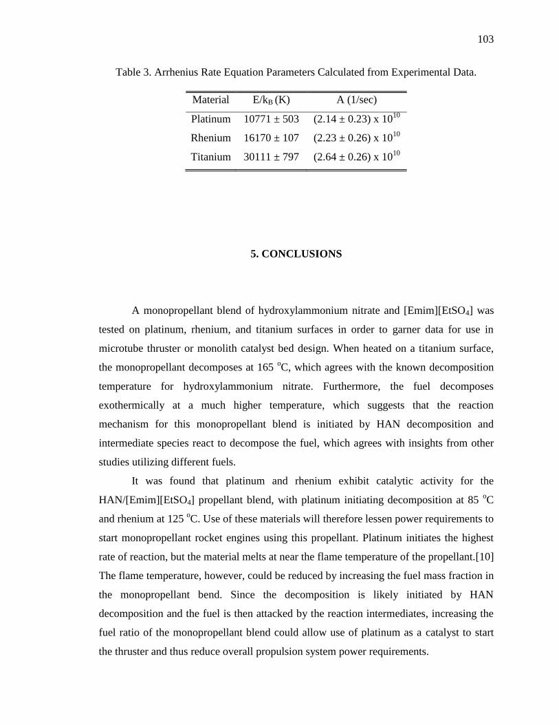
103
Table 3. Arrhenius Rate Equation Parameters Calculated from Experimental Data.
Material E/kB (K) A (1/sec)
Platinum 10771 ± 503 (2.14 ± 0.23) x 1010
Rhenium 16170 ± 107 (2.23 ± 0.26) x 1010
Titanium 30111 ± 797 (2.64 ± 0.26) x 1010
5. CONCLUSIONS
A monopropellant blend of hydroxylammonium nitrate and [Emim][EtSO4] was
tested on platinum, rhenium, and titanium surfaces in order to garner data for use in
microtube thruster or monolith catalyst bed design. When heated on a titanium surface,
the monopropellant decomposes at 165 oC, which agrees with the known decomposition
temperature for hydroxylammonium nitrate. Furthermore, the fuel decomposes
exothermically at a much higher temperature, which suggests that the reaction
mechanism for this monopropellant blend is initiated by HAN decomposition and
intermediate species react to decompose the fuel, which agrees with insights from other
studies utilizing different fuels.
It was found that platinum and rhenium exhibit catalytic activity for the
HAN/[Emim][EtSO4] propellant blend, with platinum initiating decomposition at 85 oC
and rhenium at 125 oC. Use of these materials will therefore lessen power requirements to
start monopropellant rocket engines using this propellant. Platinum initiates the highest
rate of reaction, but the material melts at near the flame temperature of the propellant.[10]
The flame temperature, however, could be reduced by increasing the fuel mass fraction in
the monopropellant bend. Since the decomposition is likely initiated by HAN
decomposition and the fuel is then attacked by the reaction intermediates, increasing the
fuel ratio of the monopropellant blend could allow use of platinum as a catalyst to start
the thruster and thus reduce overall propulsion system power requirements.
104
REFERENCES
[1] C. A. Kluever, "Spacecraft Optimization with Combined Chemical-Electric
Propulsion," Journal of Spacecraft and Rockets, Vol. 32, No. 2, 1994, pp. 378-380.
[2] C. A. Kluever, "Optimal Geostationary Orbit Transfers Using Onboard Chemical-
Electric Propulsion," Journal of Spacecraft and Rockets, Vol. 49, No. 6, 2012, pp.
1174-1182.
[3] D. Y. Oh, Randolph, T., Kimbrel, S., and Martinez-Sanchez, M., "End-toEnd
Optimization of Chemical-Electric Orbit Raising Missions," Journal of Spacecraft
and Rockets, Vol. 41, No. 5, 2004, pp. 831-839.
[4] S. R. Oleson, Myers, R. M., Kluever, C. A., Riehl, J. P., Curran, F. M., "Advanced
Propulsion for Geostationary Orbit Insertion and North-South Station Keeping,"
Journal of Spacecraft and Rockets, Vol. 34, No. 1, 1997, pp. 22-28.
[5] B. R. a. R. Donius, J. L., "Ionic Liquid Dual-Mode Spacecraft Propulsion
Assessment," Journal of Spacecraft and Rockets, Vol. 48, No. 1, 2011, pp. 110-123.
[6] T. Rexius, and Holmes, M., "Mission Capability Gains from Multi-Mode Propulsion
Thrust Profile Variations for a Plane Change Maneuver," AIAA Modeling and
Simulation Technologies Conference, AIAA Paper 2011-6431, 2011.
[7] J. M. Haas, and Holmes, M. R., "Multi-Mode Propulsion System for the Expansion of
Small Satellite Capabilities," NATO, Rept. MP-AVT-171-05, 2010.
[8] S. P. Berg, and Rovey, J. L., "Assessment of Multi-Mode Spacecraft Micropropulsion
Systems," 50th AIAA/ASME/SAE/ASEE Joint Propulsion Conference, AIAA Paper
2014-3758, 2014.
[9] S. P. Berg, and Rovey, J. L., "Assessment of High-Power Electric Multi-Mode
Spacecraft Propulsion Concepts," 33rd International Electric Propulsion Conference,
IEPC-2013-308, 2013.
105
[10] S. P. Berg, and Rovey, J. L., "Assessment of Imidazole-Based Energetic Ionic
Liquids as Dual-Mode Spacecraft Propellants," Journal of Propulsion and Power,
Vol. 29, No. 2, 2013, pp. 339-351.
[11] S. P. Berg, and Rovey, J. L., "Decomposition of Monopropellant Blends of
Hydroxylammonium Nitrate and Imidazole-Based Ionic Liquid Fuels," Journal of
Propulsion and Power, Vol. 29, No. 1, 2013, pp. 125-135.
[12] C. A. Mento, Sung, C-J., Ibarreta, A. F., Schneider, S. J.,, "Catalyzed Ignition of
Using Methane/Hydrogen Fuel in a Microtube for Microthruster Applications,"
Journal of Propulsion and Power, Vol. 25, No. 6, 2009, pp. 1203-1210.
[13] G. A. Boyarko, Sung, C-J., Schneider, S. J.,, "Catalyzed Combustion of Hydrogen-
Oxygen in Platinum Tubes for Micro-Propulsion Applications," Proceedings of the
Combustion Institute, Vol. 30, No. 2005, pp. 2481-2488.
[14] S. J. Volchko, Sung, C-J., Huang, Y., Schneider, S. J.,, "Catalytic Combustion of
Rich Methane/Oxygen Mixtures for Micropropulsion Appications," Journal of
Propulsion and Power, Vol. 22, No. 3, 2006, pp. 684-693.
[15] S. P. Berg, Rovey, J. L., Prince, B. P., Miller, S. W., and Bemish, R.J., "Electrospray
of and Energetic Ionic Liquid Propellant for Multi-Mode Micropropulsion
Applications," 51st AIAA/ASME/SAE/ASEE Joint Propulsion Conference, AIAA
Paper 2015-4011, 2015.
[16] G. P. Sutton, and Biblarz, O., Rocket Propulsion Elements, 7th, Wiley, New York,
2001.
[17] D. Amariei, Courtheoux, L., Rossignol, S., Batonneau, Y., Kappenstein, C., Ford,
M., and Pillet, N., "Influence of the Fuel on Thermal and Catalytic Decompositions
of Ionic Liquid Monopropellants," 41st AIAA/ASME/SAE/ASEE Joint Propulsion
Conference & Exhibit, AIAA Paper 2005-3980, 2005.
[18] K. Anflo, Gronland, T. A., Bergman, G., Johansson, M., and Nedar, R., "Towards
Green Propulsion for Spacecraft with ADN-Based Monopropellants," 38th
AIAA/ASME/SAE/ASEE Joint Propulsion Conference & Exhibit, AIAA Paper
2002-3847, 2002.
106
[19] B. Slettenhaar, Zevenbergen, J. F., Pasman, H. J., Maree, A. G. M., and Morel, J. L.
P. A., "Study on Catalytic Ignition of HNF Based Non Toxic Monopropellants,"
39th AIAA/ASME/SAE/ASEE Joint Propulsion Conference & Exhibit, AIAA Paper
2003-4920, 2003.
[20] K. Anflo, Persson, S., Thormahlen, P., Bergman, G., and Hasanof, T., "Flight
Demonstration of ADN-Based Propulsion System on the PRISMA Satellite," 42nd
AIAA/ASME/SAE/ASEE Joint Propulsion Conference & Exhibit, AIAA Paper
2006-5212, 2006.
[21] Y. P. Chang, Josten, J.K., Zhang, B.Q., Kuo, K.K.,, "Combustion Characteristics of
Energetic HAN/Methanol Based Monopropellants," 38th AIAA Joint Propulsion
Conference, AIAA Paper 2002-4032, 2002.
[22] C. H. McLean, Deininger, W. D., Joniatis, J., Aggarwal, P. K., Spores, R. A., Deans,
M., Yim, J. T., Bury, K., Martinez, J., Cardiff, E. H., Bacha, C. E., "Green Propellant
Infusion Mission Program Development and Technology Maturation," 50th
AIAA/ASME/SAE/ASEE Joint Propulsion Conference, AIAA Paper 2014-3481,
2014.
[23] Green Monopropellant Thrusters, http://www.busek.com/index_htm_files/70008517B.pdf
[24] Busek Electrospray Thrusters, http://www.busek.com/index_htm_files/70008500E.pdf
[25] Chiu, Y., Dressler, A.,, "Ionic Liquids For Space Propulsion", Ionic Liquids IV: Not
Just Solvents Anymore, Vol. 975, American Chemical Society, Washington, D. C.,
2007, Ch.
[26] M. Gamero-Castano, "Characterization of a Six-Emitter Colloid Thruster Using a
Torsional Balance," Journal of Propulsion and Power, Vol. 20, No. 4, 2004, pp. 736-
741.
[27] M. S. Alexander, Stark, J., Smith, K. L., Stevens, B., Kent, B., "Electrospray
Performance of Microfabricated Colloid Thruster Arrays," Journal of Propulsion and
Power, Vol. 22, No. 3, 2006, pp. 620-627.
107
[28] R. Eloirdi, Rossignol, S., Kappenstein, C., Duprez, D., Pillet, N., "Design and Use of
a Batch Reactor for Catalytic Decomposition of Propellants," Journal of Propulsion
and Power, Vol. 19, No. 2003, pp. 213-219.
[29] E. W. Schmidt, "Hydroxylammonium Nitrate Compatibility Tests with Various
Materials-A Liquid Propellant Study," U.S. Army Ballistic Research Laboratory,
Rept. BRL-CR-636, 1990.
[30] A. J. Alfano, Mills, J. D., Vaghjiani, G. L., "Resonant Laser Ignition Study of HAN-
HEHN Propellant Mixture," Combustion Science and Technology, Vol. 181, No. 6,
2009, pp. 902-913.
[31] S. R. Vosen, "Hydroxylammonium Nitrate-Based Liquid Propellant Combustion-
Interpretation of Strand Burner Data and the Laminar Burning Velocity,"
Combustion and Flame, Vol. 82, No. 1990, pp. 376-388.
[32] H.-S. Lee, Litzinger, T. A.,, "Chemical Kinetic Study of HAN Decomposition,"
Combustion and Flame, Vol. 135, No. 2003, pp. 151-169.
[33] Y.-P. Chang, "Combustion Behavior of HAN-Based Liquid Propellants,"
Mechanical Engineering, Pennsylvania State University, 2002.
108
IV. Electrospray of an Energetic Ionic Liquid Monopropellant for Multi-Mode
Micropropulsion Applications
Steven P. Berg and Joshua L. Rovey
Missouri University of Science and Technology, Rolla, Missouri, 65409
Benjamin D. Prince , Shawn W. Miller and Raymond J. Bemish
Air Force Research Laboratory, Kirtland AFB, Albuquerque, New Mexico, 87117
ABSTRACT
The multi-mode chemical-electric propulsion capable energetic ionic liquid
propellant [Emim][EtSO4]-HAN is electrosprayed in a 100 μm capillary emitter to test
the electric-mode performance of the propellant. The ionic liquid exhibits stable
electrospray emission in both cation and anion extraction modes at a nominal extraction
voltage of 3400 V. Near field measurements of current and mass flow rate distribution
are taken at flow rates from 0.19 nL/s to 3.06 nL/s. Total emission current, as measured
by Faraday cup and integrated, increases from 754 nA to 3195 nA for cation emission
and from 552 nA to 2012 nA for anion emission. The thrust and specific impulse at 0.19
nL/s flow rate is 1.08 μN and 412 seconds, respectively, with a beam power of 2.22 mW.
At 3.06 nL/s, the thrust is 8.71 μN and the specific impulse is 204 seconds with a beam
power of 8.85 mW. Extrapolation of the current data shows that specific impulse in
excess of 1000 seconds is achievable through optimized feed system and emitter design.
NOMENCLATURE
Dc = transport capillary inner diameter [μm]
109
Dn = emitter inner diameter [μm]
F = thrust [μN]
g0 = constant to convert specific impulse to units of seconds [m/s2]
I = current [nA]
Isp = specific impulse [sec]
K = ionic liquid electrical conductivity [S/m]
Lc = length of transport capillary [cm]
Ln = length of capillary emitter [cm]
�̇� = mass flow rate [ng/s]
m/q = mass to charge ratio [amu/e]
P0 = reservoir pressure [torr]
Pc = pressure in transport capillary [torr]
Pn = pressure at capillary emitter [torr]
Q = volumetric flow rate [nL/s]
Vacc = acceleration voltage [V]
VE = extractor voltage [V]
VN = emitter voltage [V]
γ = ionic liquid surface tension [N/m]
ε = ionic liquid dielectric constant
ε0 = permittivity of free space [F/m]
μl = viscosity of propellant [cP]
ρ = ionic liquid density [g/cm3]
1. INTRODUCTION
Multi-mode spacecraft propulsion is the use of two or more types of propulsive
devices on a spacecraft that share some commonality in terms of either hardware or
propellant. An example is the Mars Global Surveyor, which made use of hydrazine as

110
both a monopropellant for attitude control and a bipropellant for primary maneuvering.[1]
Specific to this study is a multi-mode system making use of a high-thrust, usually
chemical, mode and a high-specific impulse, electric mode. Using these two modes can
be beneficial in two primary ways. One way is by designing a mission such that the high-
thrust and high-specific impulse maneuvers are conducted in such a way that it provides a
more optimum trajectory over a single chemical or single electric maneuver.[2-5] The
second is to increase the mission flexibility of a single spacecraft architechture in that
both high-thrust and high-specific impulse maneuvers are available to mission designers
at will, perhaps even allowing for drastic changes in the mission plan while on-orbit or
with a relatively short turnaround from concept to launch.[6-10] For the second method,
it is extremely beneficial to utilize a common propellant for both modes as this provides
the highest flexibility in terms of mission design choices.[9] Previous research has
investigated a multi-mode system utilizing a single ionic liquid propellant for chemical
monopropellant and electrospray modes.[6, 11] Two propellants were developed that may
not only function, but theoretically perform well in both a modes.[11] These propellants,
based on binary mixtures of ionic liquid fuels [Emim][EtSO4] and [Bmim][NO3] with
ionic liquid oxidizer hydroxylammonium nitrate (HAN), have been previously
synthesized and tested for thermal and catalytic decomposition in a microreactor.[12]
This paper presents results of experiments measuring the performance of the electrospray
emitter and beam composition of the [Emim][EtSO4]-HAN propellant. In a separate
paper, the decomposition and performance of this propellant in the chemical, high-thrust
mode thruster has been investigated.[13]
Recent efforts have placed a greater emphasis on smaller spacecraft, specifically
microsatellites (10-100 kg) and nanosatellites (1-10 kg), including the subset of
cubesats.[14] Many different types of thrusters have been proposed to meet the stringent
mass and volume requirements placed on spacecraft of this type. Electrospray, in
particular, may be well suited for micropropulsion, and has been selected for these types
of applications.[15-17] Several types of thrusters have been proposed for chemical
propulsion for small spacecraft. One type is the chemical microtube.[18-20] This type of
thruster is simply a heated tube of diameter ~1 mm or less that may or may not consist of
a catalytic surface material. Additionally, and ideally from a multi-mode system
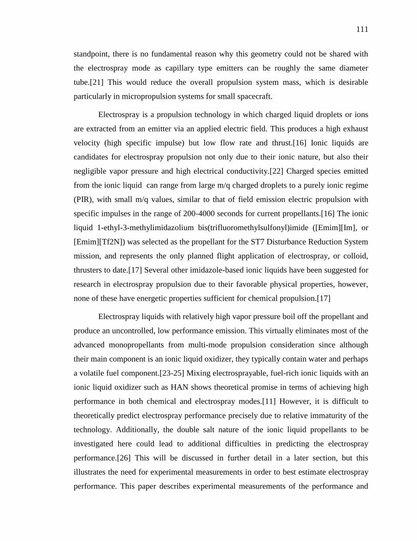
111
standpoint, there is no fundamental reason why this geometry could not be shared with
the electrospray mode as capillary type emitters can be roughly the same diameter
tube.[21] This would reduce the overall propulsion system mass, which is desirable
particularly in micropropulsion systems for small spacecraft.
Electrospray is a propulsion technology in which charged liquid droplets or ions
are extracted from an emitter via an applied electric field. This produces a high exhaust
velocity (high specific impulse) but low flow rate and thrust.[16] Ionic liquids are
candidates for electrospray propulsion not only due to their ionic nature, but also their
negligible vapor pressure and high electrical conductivity.[22] Charged species emitted
from the ionic liquid can range from large m/q charged droplets to a purely ionic regime
(PIR), with small m/q values, similar to that of field emission electric propulsion with
specific impulses in the range of 200-4000 seconds for current propellants.[16] The ionic
liquid 1-ethyl-3-methylimidazolium bis(trifluoromethylsulfonyl)imide ([Emim][Im], or
[Emim][Tf2N]) was selected as the propellant for the ST7 Disturbance Reduction System
mission, and represents the only planned flight application of electrospray, or colloid,
thrusters to date.[17] Several other imidazole-based ionic liquids have been suggested for
research in electrospray propulsion due to their favorable physical properties, however,
none of these have energetic properties sufficient for chemical propulsion.[17]
Electrospray liquids with relatively high vapor pressure boil off the propellant and
produce an uncontrolled, low performance emission. This virtually eliminates most of the
advanced monopropellants from multi-mode propulsion consideration since although
their main component is an ionic liquid oxidizer, they typically contain water and perhaps
a volatile fuel component.[23-25] Mixing electrosprayable, fuel-rich ionic liquids with an
ionic liquid oxidizer such as HAN shows theoretical promise in terms of achieving high
performance in both chemical and electrospray modes.[11] However, it is difficult to
theoretically predict electrospray performance precisely due to relative immaturity of the
technology. Additionally, the double salt nature of the ionic liquid propellants to be
investigated here could lead to additional difficulties in predicting the electrospray
performance.[26] This will be discussed in further detail in a later section, but this
illustrates the need for experimental measurements in order to best estimate electrospray
performance. This paper describes experimental measurements of the performance and
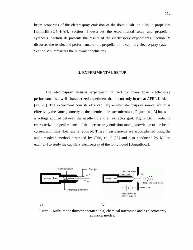
112
beam properties of the electrospray emission of the double salt ionic liquid propellant
[Emim][EtSO4]-HAN. Section II describes the experimental setup and propellant
synthesis. Section III presents the results of the electrospray experiments. Section IV
discusses the results and performance of the propellant in a capillary electrospray system.
Section V summarizes the relevant conclusions.
2. EXPERIMENTAL SETUP
The electrospray thruster experiment utilized to characterize electrospray
performance is a well-characterized experiment that is currently in use at AFRL Kirtland
[27, 28]. The experiment consists of a capillary emitter electrospray source, which is
effectively the same geometry as the chemical thruster microtube, Figure 1a,[13] but with
a voltage applied between the needle tip and an extractor grid, Figure 1b. In order to
characterize the performance of the electrospray emission mode, knowledge of the beam
current and mass flow rate is required. These measurements are accomplished using the
angle-resolved method described by Chiu, et. al.[28] and also conducted by Miller,
et.al.[27] to study the capillary electrospray of the ionic liquid [Bmim][dca].
a) b)
Figure 1. Multi-mode thruster operated in a) chemical microtube and b) electrospray
emission modes.
113
2.1. APPARATUS
A schematic of the instrumentation to diagnose the electrospray emission in the
near-field is shown in Figure 2. The electrospray source, as in Figure 1b, consists of a
capillary and extractor plate. The capillary is 100 µm internal diameter, 5.0 cm long, and
has a tapered tip. The capillary is fed from a propellant reservoir via a 100 µm internal
diameter fused silica transport capillary 82.5 cm in length. The feed system is a pressure-
fed system similar to that used by Lozano[29] and is shown in Figure 3. Notable
differences include direct feed pressure monitoring via a pressure transducer and the fact
the reservoir, after achieving nominal pressure, is isolated by closing both shut-off valves
and operates in blow-down mode. Since the volume change of the propellant in the
reservoir is negligible during normal test opertions (~nL/s flow rate from a ~10 mL
reservoir), reservoir pressure, and thus flow rate, can safely be assumed to be constant
during the experiment under steady flow conditions. The extractor plate consists of a
metal plate with a 1.5 mm orifice to allow for passage of the electrospray beam.
The electrospray source is attached to a rotation stage, which allows the beam to
be rotated in order to capture species in the full width of the beam divergence. These
measurements allow for computation of the thrust, specific impulse, and efficiency of the
electrospray thruster. A Faraday cup and quartz crystal microbalance (QCM) measure the
current and mass flow rate of the electrospray beam. Appatures of 0.8 mm are used on
both targets located 18 mm downstream of the emission source, and the measurement
interval is at minimum 2.5 degrees for all angle-resolved measurements described in this
paper.

114
Figure 2. Electrospray experiment near-field diagnostics. [27, 28]
Figure 3. Plumbing and instrumentation diagram of the electrospray apparatus.[27]
While the experiment itself is well characterized with various ionic liquids, there
are notable differences between ionic liquids previously investigated with the setup and
the ionic liquid propellants proposed in this study. The major difference is that previously
only single ionic liquids have been used. The multi-mode propellants proposed here are
115
mixtures of two ionic liquids. Furthermore, the term mixture is actually a misnomer and
these may in fact be more accurately referred to as double salt ionic liquids [26]. The
reason is in the fundamental nature of ionic liquids, in that they are essentially dissociated
pairs of cations and anions in solution. Therefore mixing two ionic liquids could result in
not only pairs of the original constituents, but also pairs of the swapped ions. For
example, a mixture of two ionic liquids [A]+[B]
- and [C]
+[D]
- could consist of a mixture
of [A]+[B]
-, [C]
+[D]
-, [A]
+[D]
-, [C]
+[B]
- in some ratio. While trends in the literature
predict that the physical properties for double salt ionic liquids in general follow typical
mixing laws [26], this could fundamentally alter the species emitted in the electrospray
beam, and thus have an effect on the electrospray thruster performance of the ionic liquid
propellants.
2.2. PROPELLANT SYNTHESIS
The propellant synthesis method for the binary mixture of [Emim][EtSO4]-HAN
was developed in a previous study,[12] however it is repeated here making particular note
of the considerations made to ensure successful electrospray operation. Pure 1-ethyl-3-
methylimidazolium ethyl sulfate, [Emim][EtSO4] (95% purity), and hydroxylammonium
nitrate, HAN, (24% in water) were purchased from Sigma Aldrich. Pure crystalline HAN
was obtained by removing water in high-vacuum (~10-6
torr) for ~8 h. Additionally,
[Emim][EtSO4] was placed in high vacuum for ~8h to remove any volatile impurities.
Crystalline HAN was then added to the [Emim][EtSO4] in a sealable container in the
desired ratio; for this study the ratio is 59% HAN, 41% [Emim][EtSO4] by weight. This
ratio was chosen mostly to avoid sooting and burn through in the chemical mode and is
described more in the previous studies with this propellant.[11,12] This mixture was
allowed to settle overnight at which point solid HAN was no longer visible in the
mixture. This process likely could be sped up by mechanically agitating the mixture to
allow for faster dissolving. However, due to safety concerns involved with creating the
potentially explosive monopropellant, this was avoided, and is not recommended. The
propellant reservoir in the electrospray experiment described in this paper was kept under
rough vacuum (< 100 mTorr) when not in operation to prevent water absorption.
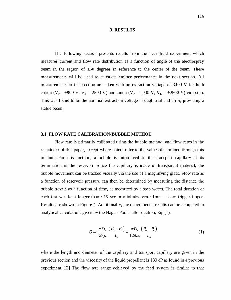
116
3. RESULTS
The following section presents results from the near field experiment which
measures current and flow rate distribution as a function of angle of the electrospray
beam in the region of ±60 degrees in reference to the center of the beam. These
measurements will be used to calculate emitter performance in the next section. All
measurements in this section are taken with an extraction voltage of 3400 V for both
cation (VN =+900 V, VE =-2500 V) and anion (VN = -900 V, VE = +2500 V) emission.
This was found to be the nominal extraction voltage through trial and error, providing a
stable beam.
3.1. FLOW RATE CALIBRATION-BUBBLE METHOD
Flow rate is primarily calibrated using the bubble method, and flow rates in the
remainder of this paper, except where noted, refer to the values determined through this
method. For this method, a bubble is introduced to the transport capillary at its
termination in the reservoir. Since the capillary is made of transparent material, the
bubble movement can be tracked visually via the use of a magnifying glass. Flow rate as
a function of reservoir pressure can then be determined by measuring the distance the
bubble travels as a function of time, as measured by a stop watch. The total duration of
each test was kept longer than ~15 sec to minimize error from a slow trigger finger.
Results are shown in Figure 4. Additionally, the experimental results can be compared to
analytical calculations given by the Hagan-Pouiseulle equation, Eq. (1),
4 40
128 128
n n cc n
l c l n
P P P PD DQ
L L
(1)
where the length and diameter of the capillary and transport capillary are given in the
previous section and the viscosity of the liquid propellant is 130 cP as found in a previous
experiment.[13] The flow rate range achieved by the feed system is similar to that
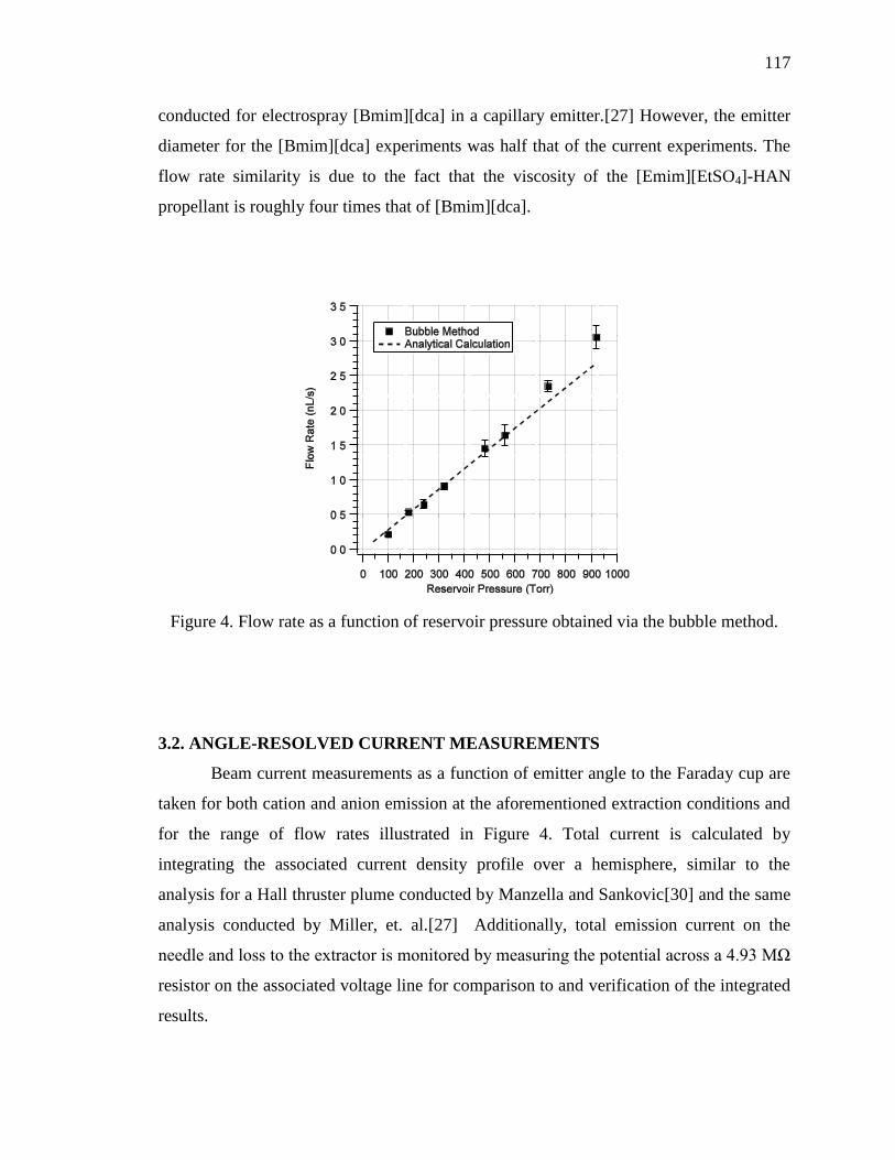
117
conducted for electrospray [Bmim][dca] in a capillary emitter.[27] However, the emitter
diameter for the [Bmim][dca] experiments was half that of the current experiments. The
flow rate similarity is due to the fact that the viscosity of the [Emim][EtSO4]-HAN
propellant is roughly four times that of [Bmim][dca].
Figure 4. Flow rate as a function of reservoir pressure obtained via the bubble method.
3.2. ANGLE-RESOLVED CURRENT MEASUREMENTS
Beam current measurements as a function of emitter angle to the Faraday cup are
taken for both cation and anion emission at the aforementioned extraction conditions and
for the range of flow rates illustrated in Figure 4. Total current is calculated by
integrating the associated current density profile over a hemisphere, similar to the
analysis for a Hall thruster plume conducted by Manzella and Sankovic[30] and the same
analysis conducted by Miller, et. al.[27] Additionally, total emission current on the
needle and loss to the extractor is monitored by measuring the potential across a 4.93 MΩ
resistor on the associated voltage line for comparison to and verification of the integrated
results.
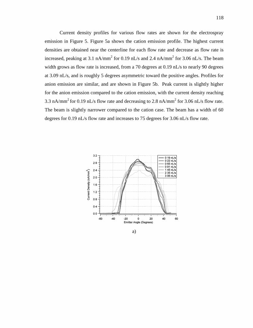
118
Current density profiles for various flow rates are shown for the electrospray
emission in Figure 5. Figure 5a shows the cation emission profile. The highest current
densities are obtained near the centerline for each flow rate and decrease as flow rate is
increased, peaking at 3.1 nA/mm2 for 0.19 nL/s and 2.4 nA/mm
2 for 3.06 nL/s. The beam
width grows as flow rate is increased, from a 70 degrees at 0.19 nL/s to nearly 90 degrees
at 3.09 nL/s, and is roughly 5 degrees asymmetric toward the positive angles. Profiles for
anion emission are similar, and are shown in Figure 5b. Peak current is slightly higher
for the anion emission compared to the cation emission, with the current density reaching
3.3 nA/mm2
for 0.19 nL/s flow rate and decreasing to 2.8 nA/mm2 for 3.06 nL/s flow rate.
The beam is slightly narrower compared to the cation case. The beam has a width of 60
degrees for 0.19 nL/s flow rate and increases to 75 degrees for 3.06 nL/s flow rate.
a)

119
b)
Figure 5. Current density profiles for a) cation and b) anion emission of the electrospray
of [Emim][EtSO4]-HAN propellant.
Total emission current obtained by integrating the beam current profiles, along
with the measurements from the 4.93 MΩ resistor are shown in Figure 6. The integrated
current is the total current obtained by integrating the current profiles in Figure 5 via the
method described previously. The emitter current is measured on the needle and is a
measure of the overall total current of the electrospray emission. The extractor current is
the current lost to the extractor. Figure 6a shows the results from cation emission. At the
lowest flow rate conducted in the experiment, 0.19 nL/s, the total current is 680 nA. Both
the integrated and emitter current agree at low flow rates. However, due to loss to the
extractor at higher flow rates, the current measured via integration of the Faraday cup
measurements does not increase markedly although the emitter current does. At the
highest flow rate at which experiments were conducted, 3.1 nL/s, the loss to the extractor
represents nearly 2/3 of the total emission current. Current measured for anion emission
is shown in Figure 6b. The trends in total current are similar to the cation case; however,
the current at each flow rate is roughly 70% that of the cation case. The current integrated
from the angle-resolved profiles added to the current measured on the extractor agrees
well with the emitter current, within 15% for all flow rate cases.
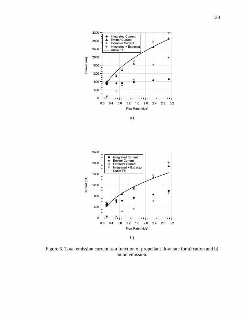
120
a)
b)
Figure 6. Total emission current as a function of propellant flow rate for a) cation and b)
anion emission.
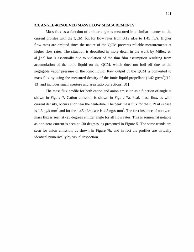
121
3.3. ANGLE-RESOLVED MASS FLOW MEASUREMENTS
Mass flux as a function of emitter angle is measured in a similar manner to the
current profiles with the QCM, but for flow rates from 0.19 nL/s to 1.45 nL/s. Higher
flow rates are omitted since the nature of the QCM prevents reliable measurements at
higher flow rates. The situation is described in more detail in the work by Miller, et.
al.,[27] but is essentially due to violation of the thin film assumption resulting from
accumulation of the ionic liquid on the QCM, which does not boil off due to the
negligible vapor pressure of the ionic liquid. Raw output of the QCM is converted to
mass flux by using the measured density of the ionic liquid propellant (1.42 g/cm3)[12,
13] and includes small aperture and area ratio corrections.[31]
The mass flux profile for both cation and anion emission as a function of angle is
shown in Figure 7. Cation emission is shown in Figure 7a. Peak mass flux, as with
current density, occurs at or near the centerline. The peak mass flux for the 0.19 nL/s case
is 1.3 ng/s-mm2 and for the 1.45 nL/s case is 4.5 ng/s-mm
2. The first instance of non-zero
mass flux is seen at -25 degrees emitter angle for all flow rates. This is somewhat notable
as non-zero current is seen at -30 degrees, as presented in Figure 5. The same trends are
seen for anion emission, as shown in Figure 7b, and in fact the profiles are virtually
identical numerically by visual inspection.
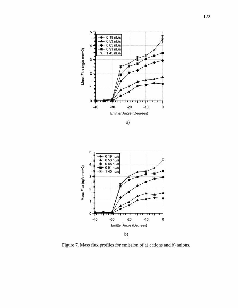
122
a)
b)
Figure 7. Mass flux profiles for emission of a) cations and b) anions.

123
The mass flux profiles are integrated over a hemisphere in the same manner as
described in the total current integration. Results of the integration are shown in Table 1
and compared to the nominal mass flow rate measured by the bubble method. As with the
current measurements, the integrated mass flow rate agrees with the nominal mass flow
rate at low flow rates. However, this quickly diverges as flow rate is increased. At the
highest flow rate, 1.45 nL/s, integration of measurements taken via the QCM results in a
roughly 50% reduced flow rate value. Also notable is that, except for the 0.22 nL/s case,
the mass flow rate obtained via integration of the QCM data is smaller than that of the
mass flow rate measured by the bubble method.
Table 1. Mass flow rate integrated from QCM data compared to bubble method.
Flow Rate
(nL/s)
Integrated Mass Flow
(ng/s)
Nominal Mass
Flow (ng/s)
%
Difference
Cation Emission
0.19 268 269 0.51
0.22 334 312 -7.27
0.65 720 922 21.89
0.91 890 1291 31.08
1.45 1012 2057 50.82
Anion Emission
0.19 265 269 1.39
0.22 394 312 26.34
0.65 679 922 26.33
0.91 967 1291 25.10
1.45 1065 2057 48.24
124
4. DISCUSSION
The near-field measurements described in the previous section provide
information on the current and mass distribution of the electrospray emission of the
double-salt ionic liquid propellant. Integration of the results from these measurements can
be used to predict the performance characteristics of the ionic liquid propellant in an
electrospray thruster. While the experiments conducted in this study do not represent the
entirety of the possible performance envelope of the propellant, results can be
extrapolated to determine the likely bounds of performance for this propellant.
4.1. CURRENT AND MASS DISTRIBUTION
The current and mass distributions of the electrospray of the [Emim][[EtSO4]-
HAN double-salt ionic liquid propellant follow trends seen in the literature.[27] Namely,
the peak current falls as flow rate is increased and the profile becomes wider, resulting in
a higher total integrated current. As noted in the previous section, the QCM data shows a
non-zero flow rate at roughly 5 degrees closer to centerline than does the current. This
supports the conclusion that much of the species comprising the outer portions of the
beam are ions, whereas the center contains higher mass droplets. The mass flow of the
ions is so small that it would not read a significant amount on the QCM.
Integrating the current data from the Faraday cup measurements and comparing to
the current obtained from measuring the voltage across a resistor on the emitter and
extractor lines shows that losses to the extractor become large as flow rate is increased.
As mentioned, at the highest flow rates conducted in this study the loss is as much as
66% of the total emission current. This can likely be mitigated with an extractor designed
and optimized for this propellant specifically; however, as will be shown in the next sub-
section, these flow rates do not represent conditions in which a thruster would likely be
operated. Adding the current obtained from the extractor resistor to the integrated current
shows good agreement with the current obtained from the emitter resistor measurements,
with most values falling within roughly 15% of each other. Though not shown in Figure
125
6, the measurement error for the resistor currents was also roughly 15%. This represented
the average of the highest and lowest values observed on a digital readout, since these
values were not instantaneously averaged via computer software but rather recorded by
hand. Thus, the error also likely represents higher than one standard deviation.
As in the study of capillary electrospray emission of [Bmim][dca], [27] total mass
flow rate calculated by integration of QCM data results agrees well with that obtained by
the bubble method at low flow rates, but diverges as flow rate is increased. Curiously, in
this study the mass flow calculated by QCM integration is lower than that of the bubble
method, whereas in the [Bmim][dca] study it was higher. During the unfortunate situation
in which a large amount of liquid was unintentionally deposited on the outer surface of
the capillary, the propellant was actually observed to boil in the high vacuum conditions
(~10-6
torr). This is likely the HAN component of the propellant. As a result, liquid
deposited on the QCM in any significant amount would contribute a negative component
to the mass flow rate during testing operations and would explain why the integrated
mass flow rate is lower than the mass flow obtained by the bubble method.
4.2. PERFORMANCE
The primary goal of this study is to predict thruster performance of the
[Emim][EtSO4]-HAN propellant operating in the electrospray mode of the proposed
multi-mode system. The current and mass flow measurments obtained experimentally are
directly used to compute performance. Thrust is calculated by Eq. (2),
𝐹 = √2𝑉𝑎𝑐𝑐𝑚𝐼̇ (2)
where the current used is the integrated current profile plus extractor current shown in
Figure 6. Although the extractor current does not contribute to actual thrust in this
experiment, it still represents thrust that could be achieved through optimized extractor
design. The specific impulse is then, Eq. (3),

126
𝐼𝑠𝑝 =𝐹
�̇�𝑔0 (3)
Current and calculated thrust values are shown in Table 2 for both cation and anion
emission separately. Thrust for both cases is on the order of μN for this single emitter
case. The thrust at the lowest flow rate is ~1 μN and increases to 9.71 μN and 7.71 μN for
the cation and anion cases, respectively, at the highest tested flow rate of 3.06 nL/s.
Thrust is roughly 17% lower for anion emission compared to cation emission, a direct
result of the lower current generated by the anion beam.
Table 2. Current, thrust, and mass to charge ratio for cation and anion emission.
Flow Rate
(nL/s)
Mass Flow
(ng/s)
Current
(nA)
Thrust
(μN)
m/q
(amu)
Cation Emission
0.19 269 754 1.18 34508
0.22 312 811 1.31 37137
0.65 922 1101 2.63 80815
0.91 1291 1439 3.56 86579
1.45 2057 1807 5.03 109860
2.35 3334 2733 7.87 117722
3.06 4342 3194 9.71 131170
Anion Emission
0.19 269 551 1.01 47170
0.22 312 547 1.08 55022
0.65 922 640 2.00 139028
0.91 1291 891 2.80 139769
1.45 2057 1110 3.94 178742
2.35 3334 1562 5.95 206000
3.06 4342 2011 7.71 208281

127
An actual thruster would likely not operate in solely cation or anion emission
mode, but rather in AC mode to prevent charge build up and eventual fouling of the
emitter. Thus, in order to gauge performance, both the cation and anion emission must be
taken into account. Table 3 shows the average thrust of the cation and anion emission at
the tested flow rates, along with the beam power and specific impulse. Power ranges from
2.22 mW at the 0.19 nL/s flow rate to 8.85 mW for the 3.06 nL/s flow rate. Thrust per
power (in μN/mW) , however, at low flow rate is roughly 0.5 and improves to roughly
1.0 at high flow rate. Specific impulse decreases as flow rate increases, with a calculated
value of 412.37 seconds at 0.19 nL/s flow rate and 204.47 seconds at 3.06 nL/s. These
values are higher than the specific impulse predicted for the chemical propulsion mode
(~180 seconds).[13]
Table 3. Thrust, power, and specific impulse for electrospray emission.
Flow Rate
(nL/s)
Mass Flow
(ng/s)
Average Thrust
(μN)
Power
(mW)
Isp
(sec)
0.19 269 1.09 2.22 412
0.22 312 1.20 2.31 390
0.65 922 2.32 2.96 255
0.91 1291 3.18 3.96 250
1.45 2057 4.49 4.96 222
2.35 3334 6.91 7.30 211
3.06 4342 8.71 8.85 204
Although the highest specific impulse measured in this study is 412 seconds, this
number could likely be improved through optimized thruster and feed system design. In
order to gauge what might be possible, scaling laws can be used to extrapolate the data
garnered in this study to possible specific impulse and thrust values. Current in the mixed
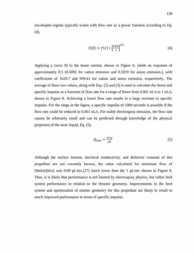
128
ion-droplet regime typically scales with flow rate as a power function according to Eq.
(4),
𝐼(𝑄) = 𝑓(𝜀) ∗ [𝛾𝐾𝑄
𝜀]0.5
(4)
Applying a curve fit to the beam current, shown in Figure 6, yields an exponent of
approximately 0.5 (0.5092 for cation emission and 0.5019 for anion emission.), with
coefficients of 1629.7 and 939.41 for cation and anion emission, respectively. The
average of these two values, along with Eqs. (2) and (3) is used to calculate the thrust and
specific impulse as a function of flow rate for a range of flows from 0.001 nL/s to 1 nL/s,
shown in Figure 8. Achieving a lower flow rate results in a large increase in specific
impulse. For the range in the figure, a specific impulse of 1000 seconds is possible if the
flow rate could be reduced to 0.001 nL/s. For stable electrospray emission, the flow rate
cannot be arbitrarily small and can be predicted through knowledge of the physical
properties of the ionic liquid, Eq. (5),
𝑄𝑚𝑖𝑛 =𝛾𝜀𝜀0
𝜌𝐾 (5)
Although the surface tension, electrical conductivity, and dielectric constant of this
propellant are not currently known, the value calculated for minimum flow of
[Bmim][dca] was 0.09 pL/sec,[27] much lower than the 1 pL/sec shown in Figure 8.
Thus, it is likely that performance is not limited by electrospray physics, but rather feed
system performance in relation to the thruster geometry. Improvements in the feed
system and optimization of emitter geometry for this propellant are likely to result in
much improved performance in terms of specific impulse.

129
Figure 8. Thrust and specific impulse of IL propellant in a capillary emitter extrapolated
from experimental data.
5. CONCLUSIONS
The double-salt, energetic ionic liquid propellant [Emim][EtSO4]-HAN exhibits
stable electrospray emission of both cations and anions in a capillary emitter of 100 μm
inner diameter with a nominal extraction voltage of 3400 V. Near-field measurements of
current and mass flow rate distribution exhibit trends similar to those of other propellants
in the literature. The peak current, in the center of the beam, decreases with increase in
mass flow rate, however the beam becomes wider and thus total integrated current
increases. Current loss to the extractor increases with increasing flow rate, but could be
mitigated with an extractor design optimized specifically for this propellant.
The lowest flow rate achieved in this experiment was 0.19 nL/s. This corresponds
to the highest specific impulse achieved in this experiment, 412.37 seconds. The thrust at
this specific impulse was calculated to be 1.09 μN, and higher thrust is possible with
higher flow rates. At the highest flow rate tested, the thrust was 8.71 μN, which also
corresponds to the highest thrust per unit power achieved in these experiments.
Extrapolation of the data obtained from the electrospray emission currents shows that
130
higher performance, in terms of specific impulse is possible. For example, if 1 pL/s flow
rate could be achieved, the specific impulse would be 1000 seconds. Examination of the
scaling laws for minimum flow rate reveals that the electrospray physics likely do not
prohibit this performance from being achieved. It is therefore likely that improvements to
the feed system and optimization of the emitter hardware in reference to this propellant
specifically can realize higher performance than achieved in these experiments.
REFERENCES
[1] S. Dominick, "Design, Development, and Flight Performance of the Mars Global
Surveyor Propulsion System," 35th AIAA Joint Propulsion Conference, AIAA
Paper 1999-2176, 1999.
[2] C. A. Kluever, "Spacecraft Optimization with Combined Chemical-Electric
Propulsion," Journal of Spacecraft and Rockets, Vol. 32, No. 2, 1994, pp. 378-380.
[3] C. A. Kluever, "Optimal Geostationary Orbit Transfers Using Onboard Chemical-
Electric Propulsion," Journal of Spacecraft and Rockets, Vol. 49, No. 6, 2012, pp.
1174-1182.
[4] D. Y. Oh, Randolph, T., Kimbrel, S., and Martinez-Sanchez, M., "End-toEnd
Optimization of Chemical-Electric Orbit Raising Missions," Journal of Spacecraft
and Rockets, Vol. 41, No. 5, 2004, pp. 831-839.
[5] S. R. Oleson, Myers, R. M., Kluever, C. A., Riehl, J. P., Curran, F. M., "Advanced
Propulsion for Geostationary Orbit Insertion and North-South Station Keeping,"
Journal of Spacecraft and Rockets, Vol. 34, No. 1, 1997, pp. 22-28.
[6] B. R. a. R. Donius, J. L., "Ionic Liquid Dual-Mode Spacecraft Propulsion
Assessment," Journal of Spacecraft and Rockets, Vol. 48, No. 1, 2011, pp. 110-123.
[7] T. Rexius, and Holmes, M., "Mission Capability Gains from Multi-Mode Propulsion
Thrust Profile Variations for a Plane Change Maneuver," AIAA Modeling and
Simulation Technologies Conference, AIAA Paper 2011-6431, 2011.

131
[8] J. M. Haas, and Holmes, M. R., "Multi-Mode Propulsion System for the Expansion of
Small Satellite Capabilities," NATO, Rept. MP-AVT-171-05, 2010.
[9] S. P. Berg, and Rovey, J. L., "Assessment of Multi-Mode Spacecraft Micropropulsion
Systems," 50th AIAA/ASME/SAE/ASEE Joint Propulsion Conference, AIAA
Paper 2014-3758, 2014.
[10] S. P. Berg, and Rovey, J. L., "Assessment of High-Power Electric Multi-Mode
Spacecraft Propulsion Concepts," 33rd International Electric Propulsion
Conference, IEPC-2013-308, 2013.
[11] S. P. Berg, and Rovey, J. L., "Assessment of Imidazole-Based Energetic Ionic
Liquids as Dual-Mode Spacecraft Propellants," Journal of Propulsion and Power,
Vol. 29, No. 2, 2013, pp. 339-351.
[12] S. P. Berg, and Rovey, J. L., "Decomposition of Monopropellant Blends of
Hydroxylammonium Nitrate and Imidazole-Based Ionic Liquid Fuels," Journal of
Propulsion and Power, Vol. 29, No. 1, 2013, pp. 125-135.
[13] S. P. Berg, and Rovey, J. L., "Ignition and Performance of Ionic Liquid Propellants
in a Microtube for Multi-Mode Micropropulsion Applications," 51st
AIAA/ASME/SAE/ASEE Joint Propulsion Conference, to be presented, 2015.
[14] Green Monopropellant Thrusters,
http://www.busek.com/index_htm_files/70008517B.pdf
[15] Busek Electrospray Thrusters,
http://www.busek.com/index_htm_files/70008500E.pdf
[16] Chiu, Y., Dressler, A.,, "Ionic Liquids For Space Propulsion", Ionic Liquids IV: Not
Just Solvents Anymore, Vol. 975, American Chemical Society, Washington, D. C.,
2007, Ch.
[17] M. Gamero-Castano, "Characterization of a Six-Emitter Colloid Thruster Using a
Torsional Balance," Journal of Propulsion and Power, Vol. 20, No. 4, 2004, pp.
736-741.
[18] C. A. Mento, Sung, C-J., Ibarreta, A. F., Schneider, S. J.,, "Catalyzed Ignition of
Using Methane/Hydrogen Fuel in a Microtube for Microthruster Applications,"
Journal of Propulsion and Power, Vol. 25, No. 6, 2009, pp. 1203-1210.

132
[19] G. A. Boyarko, Sung, C-J., Schneider, S. J.,, "Catalyzed Combustion of Hydrogen-
Oxygen in Platinum Tubes for Micro-Propulsion Applications," Proceedings of the
Combustion Institute, Vol. 30, No. 2005, pp. 2481-2488.
[20] S. J. Volchko, Sung, C-J., Huang, Y., Schneider, S. J.,, "Catalytic Combustion of
Rich Methane/Oxygen Mixtures for Micropropulsion Appications," Journal of
Propulsion and Power, Vol. 22, No. 3, 2006, pp. 684-693.
[21] M. S. Alexander, Stark, J., Smith, K. L., Stevens, B., Kent, B., "Electrospray
Performance of Microfabricated Colloid Thruster Arrays," Journal of Propulsion
and Power, Vol. 22, No. 3, 2006, pp. 620-627.
[22] I. Romero-Sanz, Bocanegra, R., Fernandez De La Mora, J., Gamero-Castano, M.,,
"Source of Heavy Molecular Ions Based on Taylor Cones of Ionic Liquids
Operating in the Pure Ion Evaporation Regime," Journal of Applied Physics, Vol.
94, No. 2003, pp. 3599-3605.
[23] D. Amariei, Courtheoux, L., Rossignol, S., Batonneau, Y., Kappenstein, C., Ford,
M., and Pillet, N., "Influence of the Fuel on Thermal and Catalytic Decompositions
of Ionic Liquid Monopropellants," 41st AIAA/ASME/SAE/ASEE Joint Propulsion
Conference & Exhibit, AIAA Paper 2005-3980, 2005.
[24] K. Anflo, Gronland, T. A., Bergman, G., Johansson, M., and Nedar, R., "Towards
Green Propulsion for Spacecraft with ADN-Based Monopropellants," 38th
AIAA/ASME/SAE/ASEE Joint Propulsion Conference & Exhibit, AIAA Paper
2002-3847, 2002.
[25] C. H. McLean, Deininger, W. D., Joniatis, J., Aggarwal, P. K., Spores, R. A., Deans,
M., Yim, J. T., Bury, K., Martinez, J., Cardiff, E. H., Bacha, C. E., "Green
Propellant Infusion Mission Program Development and Technology Maturation,"
50th AIAA/ASME/SAE/ASEE Joint Propulsion Conference, AIAA Paper 2014-
3481, 2014.
[26] G. Chatel, Pereira, J.F.B., Debbeti, V., Wang, H., Rogers, R.D.,, "Mixing Ionic
Liquids-"Simple Mixtures" or "Double Salts"?," Green Chemistry, Vol. 16, No.
2014, pp. 2051-2083.
133
[27] S. W. Miller, Prince, B.D., Bemish, R.J., Rovey, J.L.,, "Electrospray of 1-Butyl-3-
Methylimidazolium Dicyanamide Under Variable Flow Rate Operations," Journal
of Propulsion and Power, Vol. 30, No. 6, 2014, pp. 1701-1710.
[28] Y. Chiu, Gaeta, G., Levandier, D.J., Dressler, R.A., Boatz, J.A.,, "Vacuum
Electrospray Ionization Study of the Ionic Liquid, [Emim][Im]," International
Journal of Mass Spectrometry, Vol. 265, No. 2-3, 2007, pp. 146-158.
[29] P. C. Lozano, "Studies on the Ion-Droplet Mixed Regime in Colloid Thrusters,"
2003.
[30] D. H. Manzella, and Sankovic, J. M., "Hall Thruster Ion Beam Characterization,"
31st AIAA/ASME/ASEE Joint Propulsion Conference and Exhibit, AIAA Paper
1995-2927, 1995.
[31] B. A. Martin, and Hager, H. E. , "Velocity Profile on Quartz Crystals Oscillating in
Liquids," Journal of Applied Physics, Vol. 65, No. 7, 1989, pp. 2630-2635.
134
SECTION
2. CONCEPTUAL DESIGN OF A MULTI-MODE INTEGRATED
MONOPROPELLANT ELECTROSPRAY PROPULSION SYSTEM
2.1. INTRODUCTION
Results from Papers I-IV of this thesis are used to develop, conceptually, a design
for a fully integrated multi-mode propulsion system. This section is not intended to be a
fully developed, optimized, and complete design, since there are many possible options,
particularly for the thruster architecture and feed system. The intention is then to use the
methods and insights developed in the previous sections of this thesis to illustrate the
multi-mode propulsion system design process and the considerations that should be made
in approaching design of these systems.
The propulsive modes chosen for this study are chemical monopropellant and
electrospray thrusters. Specifically, as described in Paper III and IV introduction sections,
the chemical mode will be a microtube thruster, and the electric mode will be a capillary
electrospray emitter. As described, since these typically have inner diameters on the order
of tenths of a millimeter, there is no reason these could not be combined into a single
thruster head. Thus, the propulsion system described herein will be a system utilizing a
single propellant, the blend of [Emim][EtSO4] and HAN developed in Paper I and tested
in Papers III and IV, as well as a single thruster for both modes. Thus, the system is a
fully integrated propulsion system, utilizing all common components.
2.2. FEED SYSTEM ARCHITECHTURE
The largest driver for multi-mode propulsion system concepts has been the use of
a common propellant. As mentioned, using a common propellant provides the highest
level of mission flexibility. However, particularly for micropropulsion systems it is also
desirable to limit the inert mass fraction of the propulsion system as much as possible.
This particular system will utilize common thruster geometry for both modes. The feed
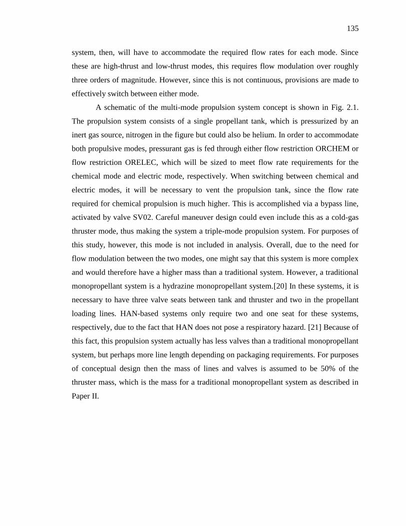
135
system, then, will have to accommodate the required flow rates for each mode. Since
these are high-thrust and low-thrust modes, this requires flow modulation over roughly
three orders of magnitude. However, since this is not continuous, provisions are made to
effectively switch between either mode.
A schematic of the multi-mode propulsion system concept is shown in Fig. 2.1.
The propulsion system consists of a single propellant tank, which is pressurized by an
inert gas source, nitrogen in the figure but could also be helium. In order to accommodate
both propulsive modes, pressurant gas is fed through either flow restriction ORCHEM or
flow restriction ORELEC, which will be sized to meet flow rate requirements for the
chemical mode and electric mode, respectively. When switching between chemical and
electric modes, it will be necessary to vent the propulsion tank, since the flow rate
required for chemical propulsion is much higher. This is accomplished via a bypass line,
activated by valve SV02. Careful maneuver design could even include this as a cold-gas
thruster mode, thus making the system a triple-mode propulsion system. For purposes of
this study, however, this mode is not included in analysis. Overall, due to the need for
flow modulation between the two modes, one might say that this system is more complex
and would therefore have a higher mass than a traditional system. However, a traditional
monopropellant system is a hydrazine monopropellant system.[20] In these systems, it is
necessary to have three valve seats between tank and thruster and two in the propellant
loading lines. HAN-based systems only require two and one seat for these systems,
respectively, due to the fact that HAN does not pose a respiratory hazard. [21] Because of
this fact, this propulsion system actually has less valves than a traditional monopropellant
system, but perhaps more line length depending on packaging requirements. For purposes
of conceptual design then the mass of lines and valves is assumed to be 50% of the
thruster mass, which is the mass for a traditional monopropellant system as described in
Paper II.
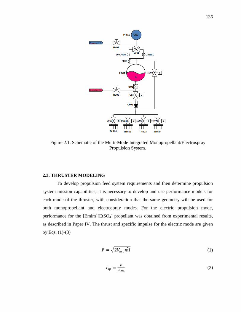
136
Figure 2.1. Schematic of the Multi-Mode Integrated Monopropellant/Electrospray
Propulsion System.
2.3. THRUSTER MODELING
To develop propulsion feed system requirements and then determine propulsion
system mission capabilities, it is necessary to develop and use performance models for
each mode of the thruster, with consideration that the same geometry will be used for
both monopropellant and electrospray modes. For the electric propulsion mode,
performance for the [Emim][EtSO4] propellant was obtained from experimental results,
as described in Paper IV. The thrust and specific impulse for the electric mode are given
by Eqs. (1)-(3)
𝐹 = √2𝑉𝑎𝑐𝑐𝑚𝐼̇ (1)
𝐼𝑠𝑝 =𝐹
�̇�𝑔0 (2)
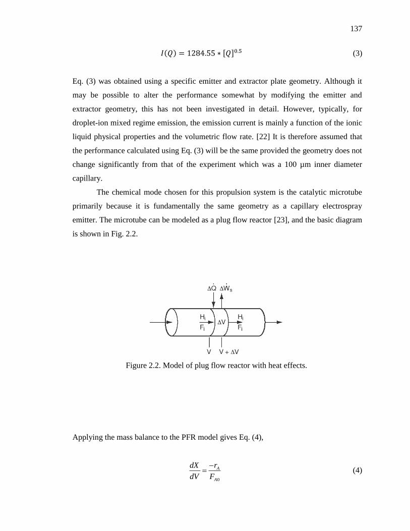
137
𝐼(𝑄) = 1284.55 ∗ [𝑄]0.5 (3)
Eq. (3) was obtained using a specific emitter and extractor plate geometry. Although it
may be possible to alter the performance somewhat by modifying the emitter and
extractor geometry, this has not been investigated in detail. However, typically, for
droplet-ion mixed regime emission, the emission current is mainly a function of the ionic
liquid physical properties and the volumetric flow rate. [22] It is therefore assumed that
the performance calculated using Eq. (3) will be the same provided the geometry does not
change significantly from that of the experiment which was a 100 µm inner diameter
capillary.
The chemical mode chosen for this propulsion system is the catalytic microtube
primarily because it is fundamentally the same geometry as a capillary electrospray
emitter. The microtube can be modeled as a plug flow reactor [23], and the basic diagram
is shown in Fig. 2.2.
Applying the mass balance to the PFR model gives Eq. (4),
0
A
A
rdX
dV F
(4)
Figure 2.2. Model of plug flow reactor with heat effects.
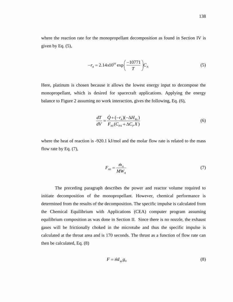
138
where the reaction rate for the monopropellant decomposition as found in Section IV is
given by Eq. (5),
10 107712.14 10 expA Ar x C
T
(5)
Here, platinum is chosen because it allows the lowest energy input to decompose the
monopropellant, which is desired for spacecraft applications. Applying the energy
balance to Figure 2 assuming no work interaction, gives the following, Eq. (6),
0
( )( )
( )
A Rx
A PA P
Q r HdT
dV F C C X
(6)
where the heat of reaction is -920.1 kJ/mol and the molar flow rate is related to the mass
flow rate by Eq. (7),
0A
A
A
mF
MW (7)
The preceding paragraph describes the power and reactor volume required to
initiate decomposition of the monopropellant. However, chemical performance is
determined from the results of the decomposition. The specific impulse is calculated from
the Chemical Equilibrium with Applications (CEA) computer program assuming
equilibrium composition as was done in Section II. Since there is no nozzle, the exhaust
gases will be frictionally choked in the microtube and thus the specific impulse is
calculated at the throat area and is 170 seconds. The thrust as a function of flow rate can
then be calculated, Eq. (8)
0spF mI g (8)

139
and the thrust as a function of volumetric flow rate for the monopropellant is shown in
Fig. 2.3.
Figure 2.3. Thrust as a Function of Flow Rate for the Chemical Microtube Propulsion
Mode.
For the chemical microtube, the flow rate cannot be arbitrarily selected. It is
limited by the flashback behavior of the propellant. HAN-based propellant burning
behavior has been investigated previously, and in general it has been found to behave
similarly to solid propellants in that a distinct linear burning rate as a function of pressure
can be determined. [24, 25] Since after ignition occurs, the reaction front will propagate
at this rate back into the chamber, it is necessary to maintain sufficient flow rate to keep
the reaction front in the microtube. Thus, the minimum flow rate necessary is governed
by the burn rate of the monopropellant. The linear burning rate for this monopropellant
was not determined as part of this study, however, for other HAN-based monopropellant
formulations is typically on the order of ~1-2 mm/s at 300 psi pressure. [25] Since this
includes a variety of different fuels combined with HAN, a value of 2 mm/s is selected as
sufficient for conceptual design. The minimum mass flow rate as a function of tube inner
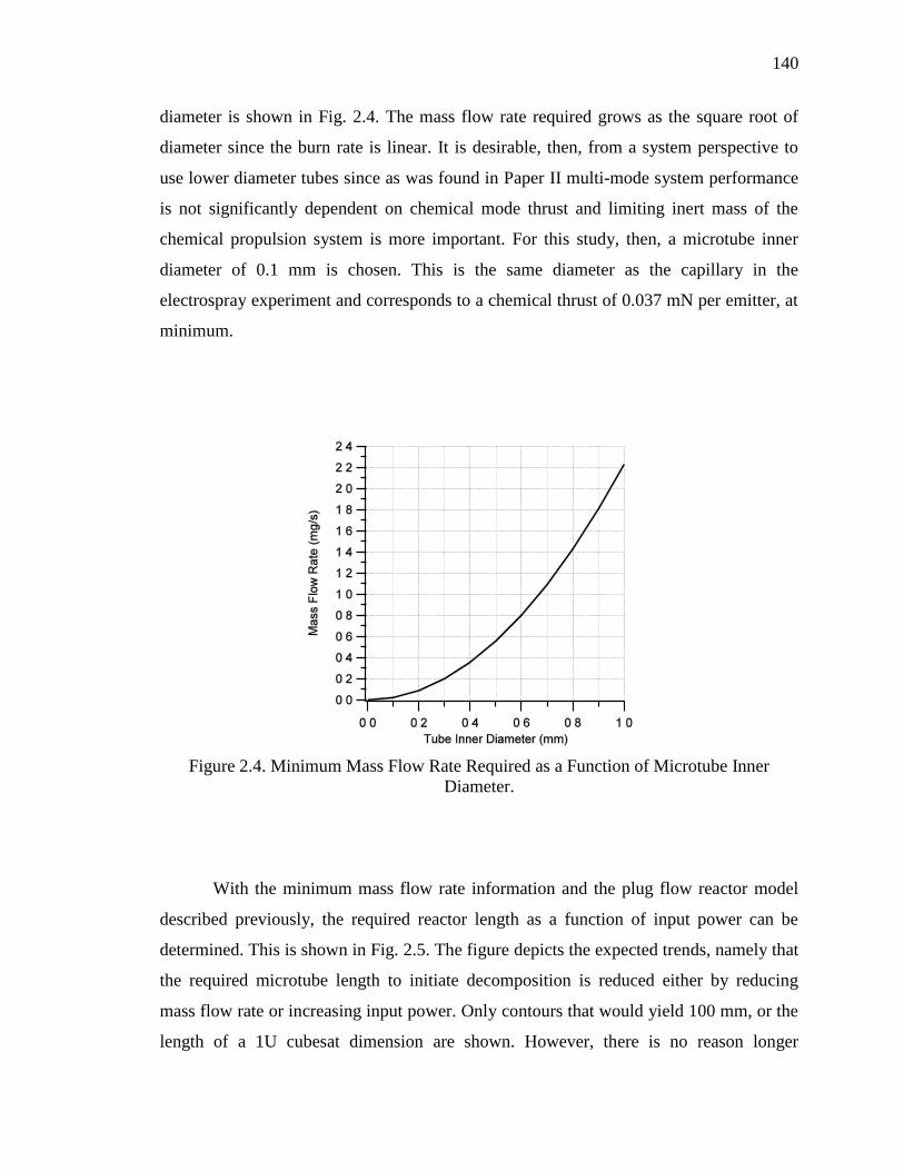
140
diameter is shown in Fig. 2.4. The mass flow rate required grows as the square root of
diameter since the burn rate is linear. It is desirable, then, from a system perspective to
use lower diameter tubes since as was found in Paper II multi-mode system performance
is not significantly dependent on chemical mode thrust and limiting inert mass of the
chemical propulsion system is more important. For this study, then, a microtube inner
diameter of 0.1 mm is chosen. This is the same diameter as the capillary in the
electrospray experiment and corresponds to a chemical thrust of 0.037 mN per emitter, at
minimum.
Figure 2.4. Minimum Mass Flow Rate Required as a Function of Microtube Inner
Diameter.
With the minimum mass flow rate information and the plug flow reactor model
described previously, the required reactor length as a function of input power can be
determined. This is shown in Fig. 2.5. The figure depicts the expected trends, namely that
the required microtube length to initiate decomposition is reduced either by reducing
mass flow rate or increasing input power. Only contours that would yield 100 mm, or the
length of a 1U cubesat dimension are shown. However, there is no reason longer
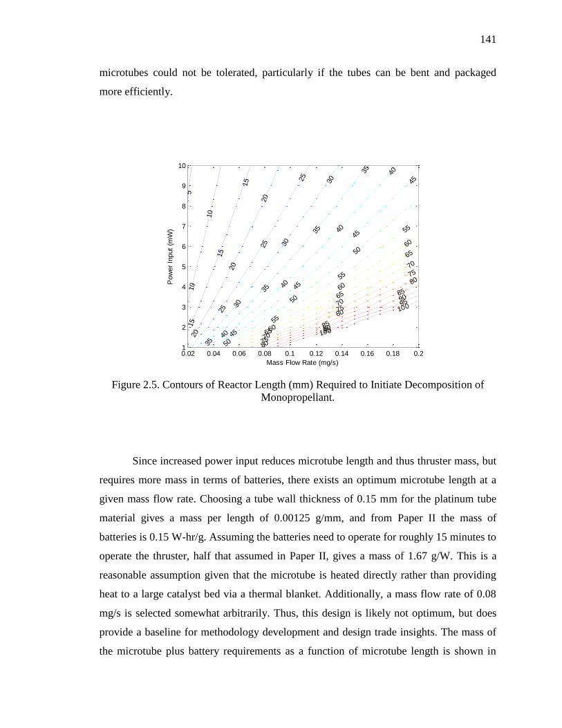
141
microtubes could not be tolerated, particularly if the tubes can be bent and packaged
more efficiently.
Figure 2.5. Contours of Reactor Length (mm) Required to Initiate Decomposition of
Monopropellant.
Since increased power input reduces microtube length and thus thruster mass, but
requires more mass in terms of batteries, there exists an optimum microtube length at a
given mass flow rate. Choosing a tube wall thickness of 0.15 mm for the platinum tube
material gives a mass per length of 0.00125 g/mm, and from Paper II the mass of
batteries is 0.15 W-hr/g. Assuming the batteries need to operate for roughly 15 minutes to
operate the thruster, half that assumed in Paper II, gives a mass of 1.67 g/W. This is a
reasonable assumption given that the microtube is heated directly rather than providing
heat to a large catalyst bed via a thermal blanket. Additionally, a mass flow rate of 0.08
mg/s is selected somewhat arbitrarily. Thus, this design is likely not optimum, but does
provide a baseline for methodology development and design trade insights. The mass of
the microtube plus battery requirements as a function of microtube length is shown in
5
10
10
15
15
15
20
20
20
25
25
25
30
30
30
35
35
35
35
40
40
40
40
45
45
45
45
50
50
50
55
55
55
60
60
60
65
65
65
70
70
70
75
75
75
80
80
80
85
85
90
90
95
95
100
100
Mass Flow Rate (mg/s)
Pow
er
Input
(mW
)
0.02 0.04 0.06 0.08 0.1 0.12 0.14 0.16 0.18 0.21
2
3
4
5
6
7
8
9
10
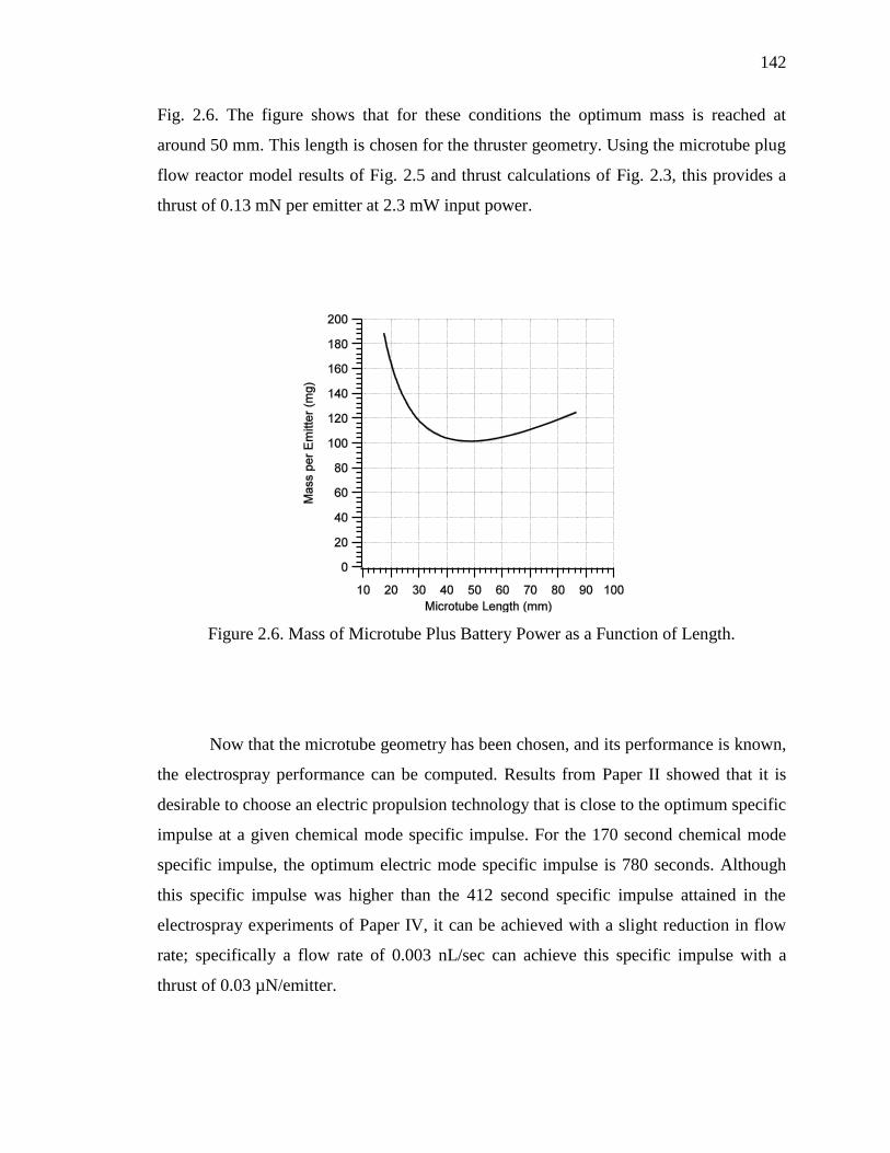
142
Fig. 2.6. The figure shows that for these conditions the optimum mass is reached at
around 50 mm. This length is chosen for the thruster geometry. Using the microtube plug
flow reactor model results of Fig. 2.5 and thrust calculations of Fig. 2.3, this provides a
thrust of 0.13 mN per emitter at 2.3 mW input power.
Figure 2.6. Mass of Microtube Plus Battery Power as a Function of Length.
Now that the microtube geometry has been chosen, and its performance is known,
the electrospray performance can be computed. Results from Paper II showed that it is
desirable to choose an electric propulsion technology that is close to the optimum specific
impulse at a given chemical mode specific impulse. For the 170 second chemical mode
specific impulse, the optimum electric mode specific impulse is 780 seconds. Although
this specific impulse was higher than the 412 second specific impulse attained in the
electrospray experiments of Paper IV, it can be achieved with a slight reduction in flow
rate; specifically a flow rate of 0.003 nL/sec can achieve this specific impulse with a
thrust of 0.03 µN/emitter.
143
The final consideration is the number of emitters to include in the thruster design.
Since multi-mode propulsion system performance is highly dependent on electric thrust,
scaling the thrust in the electric mode should be a prime consideration. Achieving 0.3 mN
of thrust, in the same range as the systems investigated in Paper II, requires 10000
emitters. This requires 6 W of power, assuming 50% powertrain efficiency. The chemical
mode thrust with this number of emitters is 1.3 N and the required power input is 23 W.
The thruster mass is 625 grams.
2.4. PROPULSION SYSTEM CAPABILITIES
As mentioned, the main motivation for using the combined thruster geometry is
reduction in propulsion system inert mass. Table 2.1 shows the propulsion system dry
mass, excluding tankage for the combined propulsion system versus a separate system
consisting of state-of-the-art thrusters in chemical and electric modes. These masses were
computed using the same methodologies as developed in Paper II, but with the relevant
design considerations from this section. It is seen that the total effect of using a combined
system, which includes reducing thruster mass by half, results in a total system mass
reduction of nearly half since the lines and valves and associated structural mounts mass
penalty is also reduced due to the reduction in thruster mass.
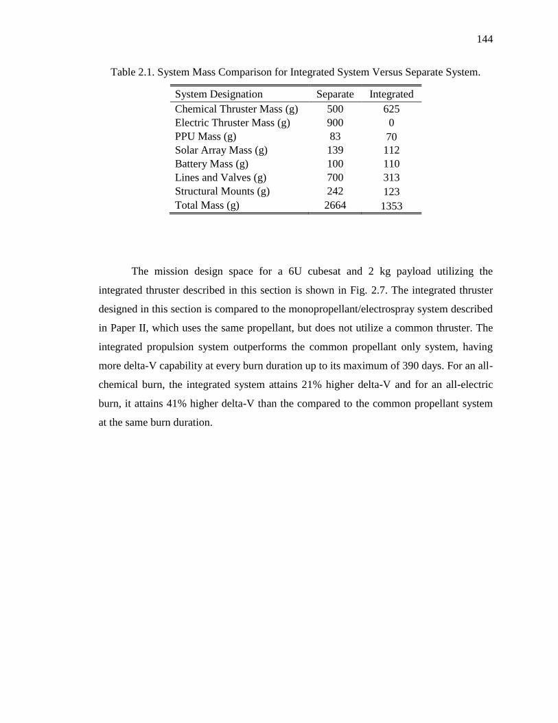
144
Table 2.1. System Mass Comparison for Integrated System Versus Separate System.
System Designation Separate Integrated
Chemical Thruster Mass (g) 500 625
Electric Thruster Mass (g) 900 0
PPU Mass (g) 83 70
Solar Array Mass (g) 139 112
Battery Mass (g) 100 110
Lines and Valves (g) 700 313
Structural Mounts (g) 242 123
Total Mass (g) 2664 1353
The mission design space for a 6U cubesat and 2 kg payload utilizing the
integrated thruster described in this section is shown in Fig. 2.7. The integrated thruster
designed in this section is compared to the monopropellant/electrospray system described
in Paper II, which uses the same propellant, but does not utilize a common thruster. The
integrated propulsion system outperforms the common propellant only system, having
more delta-V capability at every burn duration up to its maximum of 390 days. For an all-
chemical burn, the integrated system attains 21% higher delta-V and for an all-electric
burn, it attains 41% higher delta-V than the compared to the common propellant system
at the same burn duration.

145
Figure 2.7. Mission Design Space for Fully Integrated System versus Common Propellant
Only System.
REFERENCES
[1] Hass, J.M., Holmes, M.R., “Multi-Mode Propulsion System for the Expansion of
Small Satellite Capabilities,” NATO MP-AVT-171-05, 2010.
[2] Donius, B.R. “Investigation of Dual-Mode Spacecraft Propulsion by Means of
Ionic Liquids,” Masters Thesis, Department of Mechanical and Aerospace
Engineering, Missouri University of Science & Technology, Rolla, MO., May
2010.
[3] Donius, B. R., Rovey, J. L., “Ionic Liquid Dual-Mode Spacecraft Propulsion
Assessment,” Journal of Spacecraft and Rockets, Vol. 48, No. 1, 2011, pp. 110-
123.
[4] Donius, B. R., Rovey, J. L., “Analysis and Prediction of Dual-Mode Chemical
and Electric Ionic Liquid Propulsion Performance,” 48th
Aerospace Sciences
Meeting, AIAA Paper 2010-1328, 2010.
146
[5] Sutton, G. P., Biblarz, O., Rocket Propulsion Elements, 7th
ed., John Wiley &
Sons, New York, 2001, Ch. 5, 7, 19.
[6] Zube, D., Wucherer, E., Reed, B., “Evaluation of HAN-Based Propellant Blends,”
39th
AIAA Joint Propulsion Conference, AIAA Paper 2003-4643, 2003.
[7] Amariei, D., Courtheoux, L., Rossignol, S., Batonneau, Y., Kappenstein, C., Ford,
M., and Pillet, N., “Influence of the Fuel on the Thermal and Catalytic
Decompositions of Ionic Liquid Monopropellants,” 41st AIAA Joint Propulsion
Conference, AIAA, Paper 2005-3980, 2005.
[8] Anflo, K., Grönland, T. A., Bergman, G., Johansson, M., Nedar, R., “Towards
Green Propulsion for Spacecraft with ADN-Based Monopropellants,” 38th
AIAA
Joint Propulsion Conference, AIAA Paper 2002-3847, 2002.
[9] Slettenhaar, B., Zevenbergen, J. F., Pasman, H. J., Maree, A. G. M., Moerel, J. L.
P. A. “Study on Catalytic Ignition of HNF Based Non Toxic Monopropellants,”
39th
AIAA Joint Propulsion Conference. AIAA Paper 2003-4920, 2003.
[10] Anflo, K., Persson, S., Thormahlen, P., Bergman, G., Hasanof, T., “Flight
Demonstration of an ADN-Based Propulsion System on the PRISMA Satellite,”
42nd
AIAA Joint Propulsion Conference, AIAA Paper 2006-5212, 2006.
[11] Meng, H., Khare, P., Risha, G. A., Yetter, R. A., Yang, V., “Decomposition and
Ignition of HAN-Based Monopropellants by Electrolysis,” 47th
AIAA Aerospace
Sciences Meeting, AIAA Paper 2009-451, 2009.
[12] Wingborg, N., Larsson, A., Elfsberg, M., Appelgren, P., “Characterization and
Ignition of ADN-based Liquid Monopropellants,” 41st AIAA Joint Propulsion
Conference, AIAA Paper 2005-4468, 2005.
[13] Wilkes, J.S., Wasserscheid, P., Welton, T., Ionic Liquids in Synthesis, 2nd
ed.,
WILEY-VCH Verlag GmbH &Co., 2008, Ch.1.
[14] Boatz, J., Gordon, M., Voth, G., Hammes-Schiffer, S., “Design of Energetic Ionic
Liquids,” DoD HPCMP Users Group Conference, IEEE Publ., Piscataway, NJ,
Pittsburgh, 2008, pp. 196-200.
147
[15] Smiglak, M., Reichert, M. W., Holbrey, J. D., Wilkes, J. S., Sun, L., Thrasher, J.
S., Kirichenko, K., Singh, S., Katritzky, A. R., Rogers, R. D., “Combustible ionic
liquids by design: is laboratory safety another ionic liquid myth?” Chemical
Communications, Issue 24, 2006, pp. 2554-2556.
[16] Romero-Sanz, I., Bocanegra, R., Fernandez De La Mora, J., Gamero-Castano, M.,
“Source of Heavy Molecular Ions Based on Taylor Cones of Ionic Liquids
Operating in the Pure Ion Evaporation Regime,” Journal of Applied Physics, Vol.
94, 2003, pp. 3599-3605.
[17] Chiu, Y., Dressler,A., “Ionic Liquids for Space Propulsion,” In Ionic Liquids IV:
Not Just Solvents Anymore, ACS Symposium Series, Vol. 975, American
Chemical Society, Washington, DC, 2007, pp. 138-160.
[18] Gamero-Castano, M., “Characterization of a Six-Emitter Colloid Thruster Using a
Torsional Balance,” Journal of Propulsion and Power, Vol. 20, No. 4, 2004, pp.
736-741.
[19] Larriba, C., Garoz, D., Bueno, C., Romero-Sanz, I., Castro, S., Fernandez de la
Mora, J., Yoshida, Y., Saito, G., Hagiwara, R., Masumoto, K., Wilkes, J., “Taylor
Cones of Ionic Liquids as Ion Sources: The Role of Electrical Conductivity and
Surface Tension,” Ionic Liquids IV: Not Just Solvents Anymore, ACS Symposium
Series, Vol. 975, American Chemical Society, Washington, DC, 2007, Ch. 21.
[20] R. W. Humble, Henry, G. N., and Larson, W. J., Space Propulsion Analysis and
Design, McGraw-Hill, 1995.
[21] C. H. McLean, Deininger, W. D., Joniatis, J., Aggarwal, P. K., Spores, R. A.,
Deans, M., Yim, J. T., Bury, K., Martinez, J., Cardiff, E. H., Bacha, C. E., "Green
Propellant Infusion Mission Program Development and Technology Maturation,"
50th AIAA/ASME/SAE/ASEE Joint Propulsion Conference, AIAA Paper 2014-
3481, 2014.
[22] P. C. Lozano, "Studies on the Ion-Droplet Mixed Regime in Colloid Thrusters,"
2003.
148
[23] C. A. Mento, Sung, C-J., Ibarreta, A. F., Schneider, S. J.,, "Catalyzed Ignition of
Using Methane/Hydrogen Fuel in a Microtube for Microthruster Applications,"
Journal of Propulsion and Power, Vol. 25, No. 6, 2009, pp. 1203-1210.
[24] H.-S. Lee, Litzinger, T. A.,, "Chemical Kinetic Study of HAN Decomposition,"
Combustion and Flame, Vol. 135, No. 2003, pp. 151-169.
[25] Y.-P. Chang, "Combustion Behavior of HAN-Based Liquid Propellants,"
Mechanical Engineering, Pennsylvania State University, 2002.
149
VITA
Steven Paul Berg was born in 1988 in Kansas City, KS. In 1991, he moved to
Wentzville, MO and attended St. Dominic High School, graduating in 2006. In August
2006 he began his collegiate career at University of Missouri-Rolla, which changed its
name to Missouri University of Science and Technology in January 2008. He graduated
Summa Cum Laude with a Bachelors of Science in Aerospace Engineering in May 2010.
In August 2010 he began graduate school at the Missouri University of Science and
Technology. He was awarded a Master of Science in Aerospace Engineering in May
2012.
Upon completion of his Master of Science degree he decided to pursue a Ph.D.
degree in Aerospace Engineering, continuing the research developed in the M.S. phase of
his education. He completed his dissertation in the Fall of 2015 and received his Ph.D in
December of 2015. Post-graduation, he will continue to further this work through a post-
doctoral position alongside developing a small satellite business around the multi-mode
propulsion capability.


![Ionic Liquid–Liquid Chromatography: A New General ... · Ionic Liquid–Liquid Chromatography: A New General Purpose Separation Methodology ... its suitability for scale-up [27]](https://img.pdfslide.net/doc/110x75/5ed1d5db93f53a0e9e286ab4/ionic-liquidaliquid-chromatography-a-new-general-ionic-liquidaliquid-chromatography.jpg)