Embed Size (px)
Citation preview

Development of Multi-Skin Cutting Techniques
Phase 1: Preliminary Study
Deliverable D3.29
TWI-007 9-13
LaserSnake2 110128


22883/7/13 TWI Ltd
Contents
1 Introduction 1
1.1 Background 1
1.2 Suggested test geometries 1
2 Objective 1
3 Materials Used 2
4 Equipment and Procedures 2
5 Results 3
5.1 Introduction 3
5.2 Series 1 - 6mm thickness plates at various separations 3
5.3 Series 2 - Triple plate cutting 8
5.4 Series 3 - Double plate cutting using 12mm plate 8
5.5 Series 4 - Power dependence for double plate cutting 14
5.6 Stainless steel concrete sandwich 14
6 Discussion 15
6.1 Cutting plates with air gaps 15
6.2 Cutting plates with concrete in-between 15
7 Conclusions 16
8 Acknowledgements 16
9 Disclaimer 16 Table Figures 1-12
22883/7/13 1 TWI Ltd
1 Introduction
1.1 Background
NNL has supplied information on five possible multi-skinned components which will require size reduction at some point in the future. Some of these examples could also benefit from size reduction underwater: The first example is one type of pond storage container fabricated from 304L stainless
steel. The multi-skin regions are in the areas which have been reinforced to support the lifting trunnions. The resulting welded structure consists of two sections, the first containing three plates of typically 10mm thickness stainless steel such that the separation between the outer and middle plates is approximately 65mm and that between the middle and inner plate is 125mm. The second section consists of two plates separated by a distance of about 18mm.
The second example is a ‘container lid’ which is has a concrete core faced on either side by 304 stainless steel plate, of 6mm thickness. The concrete appears to have a thickness of about 110mm.
The third example consists of a dissolver vessel and cooling jacket. The cylindrical jacket wall has a typical thickness of 12mm with an air space of about 55mm before the dissolver itself. The dissolver vessel has a wall thickness of 32mm. This make close to 100mm in total. At the base of the unit, it would appear two spinnings have been used to construct the vessels and in this region the gap between the two walls might reach 100mm.
The fourth example is the top section of a dissolver basket, where a tubular ring, of wall thickness about 12mm and diameter 80mm, has been welded to the outside of a cylindrical vessel of wall thickness 19mm. The tube is covered by further plates, typically 6mm wall thickness, such that a gap of some 80mm exists between the 6mm plate and the 19mm plate, making a total thickness of 103mm. The section including cylindrical tube consists of; 6mm plate, 12mm wall tube, 54mm air gap to the other side of the tube, 12mm tube wall and 19mm vessel wall, again making 103mm in total.
The last example is a double skinned dissolver basket, where the inner perforated tube wall is approximately 20mm thickness. This is in contact (welded) with a 5mm wall thickness sleeve, which also appears perforated.
1.2 Suggested test geometries
Based on the above, two different geometries were suggested for the first series of multi-skin cutting trials: Flexible, plate/air gap geometry, for stainless steel plates:
A selection of stainless steel plates of wall thicknesses 6, 12, 20 and 32mm to be procured and drilled so that they can be assembled together using sections of tapped rod. This will easily allow several geometrical arrangements of plate thickness, plate spacing and number of plates to be assembled for cutting trials. A schematic of this arrangement can be seen in Figure 1.
Stainless steel/concrete sandwich: A series of stainless steel plates will be bonded, top and bottom, to pre-cast concrete slabs. In the first instance, 6mm plate will be used top and bottom of concrete slabs approximately 30mm thickness (paving-slabs). Based on the results obtained, further trials will be made, increasing the concrete thickness.
2 Objective
The overall objective of the work in this part of the LaserSnake2 project is to demonstrate the cutting of various multi-skinned components using both 5 and 10kW of laser power, using conventional focussing optics and to establish the process variables that contribute to the overall thickness of material that can be cut and the maximum separation between the plates.

22883/7/13 2 TWI Ltd
3 Materials Used
The cutting trials reported here were conducted on stainless steel 304L plates of dimensions, 400mm long, by 120mm wide, by 6mm and 12mm thickness. Cuts were made along the 120mm width of the material. A 30mm thick paving-slab faced with 6mm thick stainless steel plate was used for the sandwich work.
4 Equipment and Procedures
For all the trials, a multimode fibre laser was used with a maximum output power of 10kW. The beam from the laser was transmitted to the cutting head using a 200micron diameter optical fibre. In conventional laser cutting systems, the laser light arriving at the cutting head from the optical fibre first expands as it leaves the fibre and is then made parallel by a lens (the collimating lens). Below this lens, a second lens (the focussing lens) then focusses the laser light to a small spot to create the power density needed for cutting. In this work, the cutting head used was a TWI design and employed a 120mm focal length collimating lens. A focussing lens of 500mm focal length was used. The assist gas nozzle exit design allowed for nozzle tip placement such that the tip to beam focus position distance could be either 53 or 100mm. For the shorter distance a nozzle tip with an exit diameter of 2.5mm was used, whereas for the longer distance, a nozzle tip with an exit diameter of 3.5mm was used. These diameters were chosen to make sure the focussing laser beam did not clip the copper nozzle tips. Before work began, tests were performed to check that each nozzle exit was co-axially aligned with the focussing laser beam. The calculated diameter of the laser beam focussed spot was 0.8mm. The cutting head included a fused silica ‘coverslide’, to provide the cutting lens with some protection from scattered debris and dust during the trials. Compressed air, from a bottle bank, was used as the cutting assist gas. This could be turned on and off, in the program of the robot which held the cutting head.
Figure 1 The jig for holding multi-skin test components. In practice, all cuts were performed by traversing the laser beam in the horizontal plane across the material using the robot. ‘Single-pass’ cutting, where all parts of the ‘multi-skin’ were separated in one pass of the robot and ‘double-pass’ cutting, where a first pass removed the uppermost ‘skin’ and a second pass removed the lower skin, were used. For double-pass cutting, the position of the nozzle tip with respect to the uppermost surface remained the same during the second pass. Table 1 below shows the configurations of material and spacing used in the trials, along with the combinations of nozzle/focus distance and laser power used in the experiments.
Cutting table
Tapped rod
Base secured to table

22883/7/13 3 TWI Ltd
Table Configuration designation for material thickness and separation combinations used in the trials
Configuration D/double T/triple
Material thickness, mm
Separation, mm
Laser power, kW
Nozzle/focus distance, mm
C1 D 6/6 50 5 53 C2 D 6/6 25 5 53 C3 T 6/6/6 10/10 5 53 C4 D 6/6 75 5/10 53/100 C5 D 12/6 10 5 53 C6 D 12/12 8 5 53 C7 D 6/6 40 5/10 53
The compressed air supply acting as cutting assist gas was almost always applied at a pressure of 8bar, measured using a small capsule gauge attached to the cutting nozzle. Only 5 and 10kW laser powers were used and the main cutting variables were the position of the beam focus with respect to the material and the cutting speed. Top, middle (if present) and lower plates were marked for identification before each cut. In practice, for any given configuration, after setting the position of the beam focus by a vertical movement of the cutting head, cutting speed would be reduced until the plates being cut separated. The parameters were noted and the sets of samples created were photographed to reveal the cut edges, positioned for photography at the separation(s) used in the corresponding trial. Approximately 70 sets of parameters were trialled, resulting in 15 conditions which produced separation as required. These 15 sets are designated MS1 to 15 and are further described in the results section. For the work on the stainless steel/concrete sandwich, an assembly was produced by gluing two 6mm stainless steel plates to the top and bottom sides of a 30mm thickness concrete paving-slab. This was cut using a nozzle to beam focus distance of 53mm.
5 Results
5.1 Introduction
Figures 2 to 10 show the results of the experiments on cutting multiple layers of stainless steel. Each figure contains photographs of the cut edges arranged at the separations used in the experiments, along with a diagram showing the position of the laser beam focus and the corresponding ‘stand-off’ distance ie the distance between the nozzle tip and the uppermost surface of the plate closest to the cutting head. Other parameters, including laser power, nozzle to focus position distance, cutting speed and whether the result was achieved using single or double-pass cutting, are also given in each figure. For double-pass cutting the speed figure is the fastest single-speed that could be used to cut both the top and bottom plates. The results can be broken down into four series: The first investigated the effects of cutting two 6mm thickness plates at different
separation distances. The second investigated cutting of three layers of 6mm thickness stainless steel as a
function of beam focus position. The third investigated cutting two layers of thicker material. The fourth investigated the effects of using higher laser power on the cutting of two
layers of 6mm material at a fixed separation.
5.2 Series 1 - 6mm thickness plates at various separations
In this series of experiments the laser power was fixed at 5kW, the cutting assist gas pressure was fixed at 8bar, two nozzle tip to material surface distance possibilities were used and the distance between the plates varied from 25 to 75mm. Single and double-pass cutting was used. The results can be seen in Figures 2 to 5. Figure 2 shows that with the
22883/7/13 4 TWI Ltd
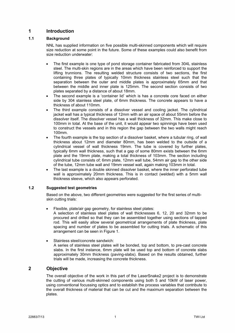
beam focus positioned mid-way between the two plates, thus providing the greatest flexibility for positioning the cutting head, at the separation of 25mm, both plates were successfully cut in a single-pass at a speed of 0.4m/min. It also shows that the effective cutting speed is faster, if a double-pass technique was employed, in that the double-pass speed of 1.0m/min is greater than twice 0.4m/min.
Figure 2 Cutting parameters for MS3 (left) and MS4 (right).
Single-pass Speed 0.4m/min; Laser power 5kW; Nozzle to focus position distance 53mm.
Double-pass Speed 1.0m/min; Laser power 5kW; Nozzle to focus position distance 53mm.

22883/7/13 5 TWI Ltd
Figure 3 Cutting parameters for MS1 (left) and MS2 (right).
Single-pass; Speed 0.2m/min; Laser power 5kW; Nozzle to focus position distance 53mm.
Double-pass; Speed 0.6m/min; Laser power 5kW; Nozzle to focus position distance 53mm.
6mm
6mm
50mm
C1
Stand‐off 10mm
MS1/2

22883/7/13 6 TWI Ltd
Figure 4 Cutting parameters for MS6
Double-pass Speed 0.3m/min; Laser power 5kW; Nozzle to focus position distance 53mm.

22883/7/13 7 TWI Ltd
Figure 5 Cutting parameters for MS11 (left) and MS12 (right).
Double-pass Speed 0.3m/min; Laser power 5kW; Nozzle to focus position distance 100mm.
Double-pass Speed 0.3m/min; Laser power 5kW; Nozzle to focus position distance 100mm.

22883/7/13 8 TWI Ltd
What can also be seen from the photographs in Figure 2, is that the edge of the uppermost cut is always better (for both cutting modes) that the lower surface. This is probably due to disruption in the gas stream by the upper layer, rather than the effect of the laser beam. Figure 3 presents essentially the same results for a greater plate separation of 50mm. In addition, the laser beam focus has been moved closer to the top surface of the lower plate. At the larger separation, it is clear that it is even more beneficial, in terms of cutting time, to perform a double-pass. Also clear, is that at this separation, using the double-pass technique provides a better edge quality (compared to the single-pass cut) on the lower plate. Figure 4 shows the results of extending the plate separation to 75mm. At this separation, using the single-pass technique it was not possible to separate both the top and bottom plates at speeds down to 0.1m/min. Using a double-pass technique, both top and bottom plates could be severed at a speed of 0.3m/min. Figure 5 shows, for the same plate configuration, the effect of switching to the longer nozzle tip to focus position distance. This reduces the effectiveness of the gas stream as a larger diameter exit hole has to be used but gains the advantage that the focus position can be moved to be on top of the lower plate surface. In this position the power density in the beam is at its highest and it could be argued this would be beneficial for cutting the lower plate. With either configuration, no successful single-pass cutting was obtained down to speeds of 0.1m/min. The maximum successful double-pass cutting was achieved at a speed of 0.3m/min, in both cases. Although there are differences between the two lower cut edges, it is difficult to decide if the change in beam focus position had a significant effect on the cutting at this plate separation.
5.3 Series 2 - Triple plate cutting
Figure 6 shows, for a return to a nozzle tip to beam focus distance of 53mm, single-pass cutting of three plates of 6mm thickness material, each separated by 10mm. Sample MS5 has the beam focus positioned at the centre of the middle plate. MS10 has the beam focus on the top of the lower plate. As can be seen from the results, there is very little difference in the maximum single-pass separation speed for either focus position. With the focus position set to the centre of the middle plate, three pass cutting was tried, but the lower plate did not separate at a speed of 0.75m/min (ie three times as fast as the single-pass speed).
5.4 Series 3 - Double plate cutting using 12mm plate
Figure 7 shows single-pass two plate cutting where the upper plate thickness is 12mm and the lower plate thickness is 6mm. with the beam focus positioned midway between the plate separation of 8mm. Under these conditions a speed of 0.2m/min was achieved for single-pass cutting. This part of the work concluded with trials to cut two layers of 12mm thickness plate separated by a gap of 8mm. For the two trials reported, the beam focus was positioned either at the top surface or the bottom surface of the lower plate. Single-pass cutting speeds for separation of both plates were 0.20 and 0.25m/min respectively. When comparing the results of MS7 and MS8, there is an indication that positioning the beam focus on the top of the lower plate is beneficial. Comparing MS8 and MS9 would indicate that pushing the beam focus even lower is also beneficial. The limit for the lowest beam focus position will be the acceptable stand-off distance between cutting tip nozzle and the top plate surface.

22883/7/13 9 TWI Ltd
Figure 6 Cutting parameters for MS5 (left) and MS10 (right).
Single-pass; Speed 0.2m/min; Laser power 5kW; Nozzle to focus position distance 53mm.
Single-pass; Speed 0.25m/min; Laser power 5kW; Nozzle to focus position distance 53mm.

22883/7/13 10 TWI Ltd
Figure 7 Cutting parameters for MS7. Single-pass: Speed: 0.2m/min; Laser power: 5kW; Nozzle to focus position distance: 53mm.

22883/7/13 11 TWI Ltd
Figure 8 Cutting parameters for MS8 (left) and MS9 (right).
Single-pass: Speed 0.25m/min; Laser power 5kW; Nozzle to focus position distance 53mm.
Single-pass: Speed 0.20m/min; Laser power 5kW; Nozzle to focus position distance 53mm.

22883/7/13 12 TWI Ltd
Single-pass: Speed 0.20m/min; Laser power 10kW; Nozzle to focus position distance 53mm. Figure 9 Cutting parameters for MS15

22883/7/13 13 TWI Ltd
Figure 10 Cutting parameters for MS13 (left) and MS14 (right)
Single-pass: Speed 0.25m/min; Laser power 5kW; Nozzle to focus position distance 53mm.
Single-pass: Speed 0.6m/min: Laser power 10kW: Nozzle to focus position distance 53mm.

22883/7/13 14 TWI Ltd
5.5 Series 4 - Power dependence for double plate cutting
For this part of the work, two 6mm thickness plates were positioned with a separation of 40mm. Two laser powers of 5 and 10kW were used. The laser beam focus position was directed either midway between the plates or on the top surface of the lower plate. For the former, at 5kW power and cutting speeds down to 0.1m/min, no separation of both plates could be achieved in a single-pass. When the laser power was increased to 10kW, separation was possible in a single-pass, at a speed of 0.3m/min. The resulting edge quality can be seen in Figure 9. However, with the focal position on the top surface of the lower plate there is a large effect of increasing the laser power. At 5kW the maximum single-pass separation speed was 0.25m/min which increased to 0.6m/min using 10kW of power. The resulting cut edges can be seen in Figure 10.
5.6 Stainless steel concrete sandwich
In the cutting trials on the concrete/stainless sandwich, as the paving stone was selected at random from a selection at a local builders merchant, trials were first conducted to check that this could be cut by laser. At 5kW laser power and 8bar assist gas pressure, trials were conducted with beam focus positions on the surface of the material, at the mid-point through the thickness of the material and at the lower surface of the material. At a travel speed of 0.2m/min successful cutting was achieved only with the beam focus at the lower edge of the material. Figure 11 shows the cut edge quality obtained at this position. Subsequent attempts were made to cut the 6mm stainless steel/concrete/6mm stainless steel sandwich.
Figure 11 Edge quality cutting a paving slab. Laser power 5kW, assist gas pressure 8bar, cutting speed 0.2m/min. At laser power of 5kW, and both 8 and 10bars assist gas pressure, it was not possible to cut through the full thickness of the sandwich at speeds of 0.2m/min. Even increasing the laser power to 10kW it was only possible to cut through the top layer of stainless steel and the paving slab. The lower layer of stainless steel was hardly marked. An image of the resulting ‘cut’ can be seen in Figure 12.

22883/7/13 15 TWI Ltd
Figure 12 The results of cutting the sandwich at a laser power of 10kW and speed of 0.2m/min.
6 Discussion
6.1 Cutting plates with air gaps
The work at 5kW with 6mm thick plates at various air gaps has shown that with gaps of at least 50mm, it appears that using a double-pass technique is more efficient (in terms of cutting time) than a single-pass technique. This is also likely to be true up to 75mm gap, as it was only possible to cut this configuration in a double-pass and attempts at single-pass cutting failed (at speeds down to 0.1m/min). In the double-pass technique, no improvement was found when changing the position of the laser beam focus. All the trials in this configuration produced better (in terms of edge quality) cuts on the top surface. The limit in the process was the lower material. The results show the importance the cutting gas stream plays in multi-skin cutting. For triple plate cutting of 6mm thick material, beam focus position had little effect on the single-pass cutting speeds achieved. The best position was with the focus positioned in the gap between the two lower plates. Again cut quality decreased on each of the three plates cut, the uppermost plate showing the best quality. For the thicker plate combinations, it would appear that the best position of the beam focus is in the region of the lower plate. Slightly better single-pass cutting speed was possible with the laser beam focus positioned at the lower surface of the lower plate. The results for cutting a double layer of 6mm plate at a separation of 40mm with laser power up to 10kW, showed that at the higher power, the effect of focus position appears to be stronger than for cutting at 5kW. This might show that applied power density is more important than gas flow, when cutting the lower plate. These results also confirmed that at least twice the cutting speed was achieved when doubling the available laser power.
6.2 Cutting plates with concrete in-between
It was clear after cutting the paving slab that this particular slab was almost pure cement containing little or no aggregate. However it was possible to cut this with the laser beam as can be seen in Figure 11, which shows a good cut quality. The cutting was very dependent

22883/7/13 16 TWI Ltd
on the laser beam focus position, however and separation was only achieved with the laser beam focus positioned at the lower surface of the material. What was disappointing is that when this slab was formed into the sandwich with the two 6mm stainless steel plates, even using 10kW of laser power it was not possible to completely separate all three parts in a single-pass when using a cutting speed of 0.2m/min. On examination, it was found that the top stainless layer and the paving slab had separated, but the lower plate showed little evidence of the laser beam. Based on the results of the work discussed in 6.1 above it might be expected that a double-pass would have successfully cut all three components of the sandwich.
7 Conclusions
This preliminary study on multi-skin cutting with 5 and 10kW of laser power has enabled the following conclusions to be drawn, based on the range of experiments conducted to-date: For the range of configurations investigated, use of 10kW laser power as opposed to
5kW, doubled the cutting speed. At 5kW laser power and using two stainless plates of thickness 6mm, it should be
possible to perform single-pass cutting at plate separations up to 50mm. For smaller plate separations double-pass cutting is likely to be the most efficient in
terms of minimizing cutting time. As the plate thickness increases or the laser power increases, there is more benefit (in
terms of cutting speed or capability to produce separation) in placing the laser beam focus in the region of the lower plate.
Cutting stainless/paving-slab/stainless sandwiches was difficult. Single-pass cutting may be complicated due to the different interactions of the beam with the different materials in the sandwich. It is possible multi-pass techniques might be better applied to these types of structures.
8 Acknowledgements
The author would like to thank Frank Nolan who conducted the cutting trials. LaserSnake2 is co-funded by the Technology Strategy Board, the Department of Energy and Climate Change and the Nuclear Decommissioning Authority, under grant number 110128.
9 Disclaimer
The data and results contained within this report are advisory in nature, expressed as an opinion only and no warranty, expressed or implied, is given as to the suitability of such advice or results for any particular purpose. The information made available by TWI Ltd over the World Wide Web does not form part of any contract. Whilst every effort has been made to ensure the accuracy of the information presented, TWI Ltd cannot accept responsibility for any errors.