Embed Size (px)
Citation preview

DEVELOPMENT OF NASA’S SPACE COMMUNICATIONS AND NAVIGATION TEST BED ABOARD ISS TO
INVESTIGATE SDR, ON-BOARD NETWORKING AND NAVIGATION TECHNOLOGIES
Abstract NASA is developing an experimental flight payload (referred to as the Space Communication
and Navigation (SCAN) Test Bed) to investigate software defined radio (SDR), networking,
and navigation technologies, operationally in the space environment. The payload consists of
three software defined radios each compliant to NASA’s Space Telecommunications Radio
System Architecture, a common software interface description standard for software defined
radios. The software defined radios are new technology developments underway by NASA
and industry partners. Planned for launch in early 2012, the payload will be externally
mounted to the International Space Station truss and conduct experiments representative of
future mission capability.
https://ntrs.nasa.gov/search.jsp?R=20100042195 2019-02-09T06:14:25+00:00Z

Development of NASA’s Space
Communications and Navigation
Test Bed aboard ISS to Investigate SDR,
On-board Networking and Navigation
Technologies
Richard C. Reinhart
CONNECT Principal Investigator
NASA Glenn Research Center
Thomas J. Kacpura, Sandra K. Johnson - NASA Glenn Research Center
and
James P. Lux, Jet Propulsion Laboratory
ReSpace - November 2010

Briefing Overview
• NASA’s shift toward use of SDRs
• NASA’s SDR Standard Open Architecture: The Space
Telecommunications Radio System (STRS) Standard
• SDR/STRS-based SCaN Testbed (Communication,
Navigation, and Networking reConfigurable Testbed,
(CONNECT), flight experiment installed on the truss of
International Space Station (ISS)
Work sponsored by the
NASA Space Communications and Navigation (SCaN) Office

Shift Towards SDR Technology
• NASA looking at how to use or infuse SDR technology into NASA
missions and infrastructure
• Assess fixed (e.g. ASIC or OTP) DSP hardware vs SDR architecture– Industry pursuing processor & FPGA-based architecture
– Enable NASA to leverage SDR developments across missions.
– In-flight Reconfigurability
Leverage commercial and NASA Labs’ (JPL, APL) SDR product lines,
with capability for typical or envisioned NASA functions and capability
• Common SDR Architecture: Platforms and waveform STRS compliant– Separation of waveform application from SDR Platform
• Abstract waveform from underlying hardware (need for standard architecture)
• Platform and waveform requirements separation
– Reduce long-term dependence on SDR developer for software upgrades

Space Telecommunications Radio System (STRS) Development Process
• Agency initiative to infuse SDR Technology and Architectures
• Established ~2005 and supported by NASA, JPL, APL, AFRL
• Industry participation through Wireless Innovation (SDR) Forum, OMG
• Provide architecture commonality among mission use of SDRs
2005 2006 2007 2008 2009 2010 2011 2012 2013 2014
NASA & Industry
SDR Work Groups
STRS
Industry DaySTRS RFI
WINN (SDR) Forum
Space Work Group
STRS Alignment with
OMG SDR Architecture
STRS/SDR Developments
for Space Experiment
(CONNECT)
STRS/SDR/Waveform
Space Experiments
(CONNECT)
Launch
STRS Standardization among
CCSDS, WINNF
STRS Rel
1.00
STRS Rel
1.01
STRS Rel
1.02
STRS Rel
Draft
STRS Rel
2.00

STRS Simplified View
• Abstract app sw from underlying HW
– Reduce mission dependence on radio
provider for reconfigurations years after
development/launch.
– Minimum set of hardware and software
interface
• Promote portability/reuse
– Avoid proprietary application designs/
implementations.
• Mission flexibility, for different levels
of available resources. – scalable
• Architecture simplified by mission
planning and hw resource allocation.
– No radio hardware discovery or dynamic
WF allocation change across hardware –
fewer resources (e.g. power, memory)
• Enable waveform component
contributions to repository for reuse

STRS Interface Highlights
6
Radio Platform
GPM(GPP)
STRS OE
WF App. (from PIM) SPM (FPGA)
WF Control:
Modulator
ST
RS
AP
I
ST
RS
HA
L
Platform Specific Wrapper
WF
Control
WF App. (from PIM)
Encoder
WF
ControlHA
L
User Data
Interface
Data
Format
ConverterH
AL
HAL
Standard Interface
for FPGA WF App.
HA
L
RFM
Data
Conversion/
Sampling
HA
LHAL
STRS API Modulator
Carrier
Synthesizer
CLK
HID
HID
HID
HID
Hardware
Abstraction Layer
Hardware Interface
Definition
Common APIs
APIs separate waveform from operating
environment – enabling waveform portability.
HID identifies hardware resources
available to waveform developer,
separating WF from HW dependency.
A waveform is the set of
transformations applied to
information transmitted over the air
and the corresponding set of
transformations to convert received
signals back to their information
contents

SDR Developer Roles
• Platform Supplier
– Hardware
– Operating Environment
• Waveform Developer
– Waveform App
• SDR Integrator
– Combines waveform
applications with the
platform.
– non-SDR model, the
integration is done at the
radio manufacturer
• System Integrator
– integrates the complete
radio (hw/wf) with the
rest of the spacecraft.

SDR Flight Experiment SCaN Testbed Mission Objectives
• SDR-based ISS NATIONAL LABORATORY Capability
– Reconfigure SDR (e.g. STRS OE, wf updates, modulation, coding, framing, filtering)
• Bit streams to arbitrary link layer protocols
– Load/run/reconfigure third party sw applications external to SDRs (flight computer)
• On-board networking (e.g. DTN), routing, and security applications
– Flexible interaction between applications and SDRs
• SDR TECHNOLOGY DEVELOPMENT
– Platform & waveforms compliant to STRS
– Separating SDR performance from link performance
– Promote development and Agency-wide adoption of NASA’s SDR Standard, STRS
• VALIDATION OF FUTURE MISSION OPERATIONAL CAPABILITIES
– Capability representative of future missions
• Comm Data rate, performance, networking/routing, navigation/GPS
– Understanding SDR performance (reliability, SEE, telemetry, instrumentation)
– Multiple and simultaneous RF Links (Ka-band, S-band, L-band/GPS)

National Aeronautics and Space Administration
www.nasa.gov 9
Communications, Navigation, and Networking
reConfigurable Test bed (CONNECT)
TDRS-W(171/174° W)
TDRS-Z (275°W)
Wallops Island Ground
Station
Commercial/
International
CoNNeCT ControlCenter
Glenn Research Center (GRC)White Sands Complex
TSC TT&C Path
S-Band
S-Band
Global Positioning System (GPS)
Constellation
S-Band
S-Band
S-Band
AFSCN
S-Band
NASA/MSFC/
JSC
(HOSC/POIC)ISS TT&C Path
Near Earth Network Communications
S-band Near EarthNetwork Communications
Lunar Surface/Relay Emulation Experiments
CONNECT SN Data Path CONNECT NEN Data Path
IP Networks
L-Band
TDRS
Space-to-
Ground
Links
Ka-Band
Advance SDR/STRS
Communications Technology to TRL-7, Compliant to STRS Common Architecture
Reprogrammable radio functions
Advancement and improvement of the STRS Standard
Multiple sources of STRS compliant radios
Next Generation Navigation
Techniques
GPS L1 and future L2 and L5
Orbit determination and relative
navigation studies
Space Network Communications
S-band and Ka-band Mission Concept & Operations
Adaptive SDR/STRS-based systems
Operational flexibility and capability
Demonstrate Cx, C3I functionality aspects
On-Orbit Networking
TechnologiesDisruptive Tolerant Networking Studies
On-board routing, security
International
Space Station
TDRS-E(41°/46° W)
(TDRS K&L)

SCAN Testbed as an External Payload on ISS
10
SCAN Testbed is located on the
ISS port (P3) ELC, mounted on the
starboard side of the P3 ELC on
the zenith/ram corner
Typical coverage to TDRSS at Ka-
band and S-band avoid solar
reflectors, thermal panels, and ISS
structure, pointing zenith
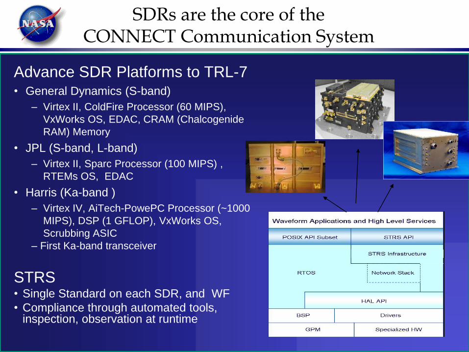
SDRs are the core of the CONNECT Communication System
Advance SDR Platforms to TRL-7• General Dynamics (S-band)
– Virtex II, ColdFire Processor (60 MIPS),
VxWorks OS, EDAC, CRAM (Chalcogenide
RAM) Memory
• JPL (S-band, L-band)
– Virtex II, Sparc Processor (100 MIPS) ,
RTEMs OS, EDAC
• Harris (Ka-band )
– Virtex IV, AiTech-PowePC Processor (~1000
MIPS), DSP (1 GFLOP), VxWorks OS,
Scrubbing ASIC
– First Ka-band transceiver
STRS• Single Standard on each SDR, and WF
• Compliance through automated tools, inspection, observation at runtime

Experiment Waveform Development Comm Technology (Launch Capability)
Transmit
(Return) Link
Receive
(Forward) Link
Platform
Provider
Waveform
Provider
Modulation User Data
Rate
(kbps)
De-
modulation
User Data
Rate
(kbps)
Coding/
Decoding
S-band DG1, Mode 1 GD GD SQPN 24, 192 QPSK 18, 72 Rate 1/2
Viterbi
S-band DG1, Mode 2 GD GD SQPN 24, 192 QPSK 18, 72 Rate 1/2
Viterbi
S-band DG1, Mode 3 GD GD QPSK <1000 QPSK 1000 Rate 1/2
Viterbi
S-band DG2 GD GD SQPSK <1000 QPSK 1000 Rate 1/2
Viterbi
S-band DG1 Mode 2 JPL GRC/GSFC BPSK 24, 96 BPSK 18, 26 Rate 1/2
Viterbi
S-band DG2 JPL GRC/GSFC BPSK 192 BSPK 72 Rate 1/2
Viterbi
Ka-band DG2 Harris Harris SQPSK 100 Mbps
12.5 Mbps
BPSK 12.5 Mbps
3 Mbps
Rate 1/2
Viterbi
12
Specific waveform variations lead to numerous configurations

Flight System Overview
• Flight Computer/Avionics
• Communication System
– SDRs
• 2 S-band SDRs (1 with GPS)
• 1 Ka-band SDR
– RF
• Ka-band TWTA
• S-band switch network
– Antennas
• 2 - low gain S-band antennas
• 1 - L-band GPS antenna
• Medium gain S-band and Ka-band
antenna on antenna pointing
subsystem.
– Antenna pointing system.
• Two gimbals
• Control electronics
• Flight enclosure provides for
thermal control/radiator surface. 13

2
GPS- LGA
Ka HGA
JPL
SDR
Dip
lexer
LNALRx
LNASRx
HPASTx
GD
SDR
LNASRx
HPASTx
Harris
SDR
LNAKaRx
KaTx
SN-MGA
GN- LGA
SN-LGA
Dip
lexer
Dip
lexerTWTA
Atte
nuato
r
Iso
lato
r
CTS2
CTS1
CTS3
SDR
Subsystem
RF
Subsystem
Antenna
Subsystem
Avionics
Subsystem
Data
Space Wire
Command/Telemetry
MIL-STD-1553
Data
Space Wire
Command/Telemetry
MIL-STD-1553
Data
Space Wire
Command/Telemetry
Space Wire
Processor
Storage
Space wire
STD-1553
Communication Verification/Experiment Baseline Plan
SCaN Testbed Flight System Configuration
14
GPS- LGA
Ka HGA
SN-MGA
GN- LGA
SN-LGA
Antenna
Subsystem

Experimenter Access Pointswithin CONNECT System
Experimenters have access to
SDRs, avionics, various ground points
ISS
CONNECT Flight System
Experiment
InterfaceExternal SystemsGround
System
SDR
Av
ion
ics
Experiment
EquipmentC
ON
NE
CT
Co
ntr
ol
Cen
ter
NISN
WSCRTN-IF
WSCLegacy
Service
SDR
T
D
R
S
SR
F
S-band
DTESDR
= Experiment Element (e.g. sw, fw, hw, component)

Initial CONNECT Experiments
• Characterize GD and JPL SDR S-band performance over TDRSS
– SDR-based TDRSS transponder (5th Gen)
– On-orbit waveform performance
• Characterize Harris SDR Ka-band Performance over TDRSS
– First Ka-band TDRSS transponder
– On-orbit waveform performance
• SDR Platform Technology Assessments
– On-orbit platform performance
• S-band and Ka-band IPv4 On-board Routing/Relay
– Avionics IP routing, waveform independent
• GPS L1, L2, L5 Navigation
– On-board GPS position determination using combination of signals
• DTN Node within SDR
– DTN bundling functions within SDR
• TDRSS Waveform Development
– Coherent mode waveforms added to launch capability

Facility
FY08-FY12
Phase I
Experiments
FY12-FY15+Phase II
• NASA, industry, academia experiments
• Unique software and mission operations
• Minimum 2 year operations planned
•Core capabilities
•Flight System development/launch
•Flight Commissioning
Announcement of Opportunity anticipated in 2011
for CONNECT Experiments for Phase II
CONNECT Phases

SDR & STRS Architecture Conclusions
• STRS Architecture
– Provides commonality among reconfigurable SDRs developed by NASA
• Provides a coordinated method across the agency to apply SDR technology
– Reduces SDR vendor dependence for waveform development
– Tailored for resource constrained domains
– Accommodates technology infusion, obsolescence
– Standardization effort among WINNF, CCSDS, OMG in 2010-2011 timeframe
• SCaN Testbed, SDR Flight Experiment aboard International Space Station
– Will provide an experiment opportunity for NASA, industry, and academia
• Comm waveform development and operation in space
• SDR-based mission concepts of operations
• Networking experiments using avionics as router between SDRs, SDR nodes
• GPS-based Navigation waveforms
– Prove out STRS among multiple SDRs in space environment
– Scheduled for launch in early 2012