Embed Size (px)
Citation preview
1
Development of New Anti-Corrosion Steel for COTs of crude oil carrier
The NSGP-1Nippon Steel’s Green Protect-1
2
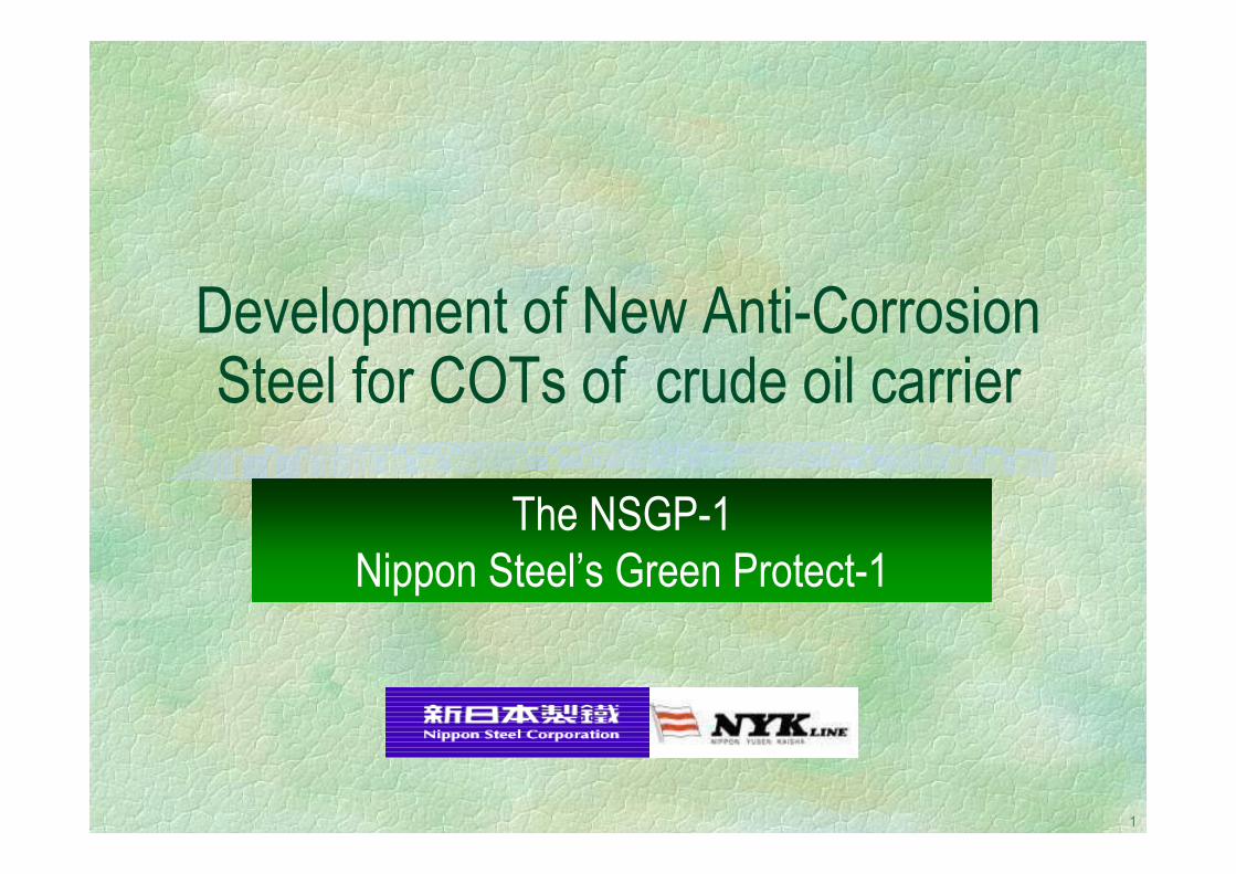
The Studies on COT Corrosion in Japan2000 2002 2004 20061998 2000 2002 2004 20061998
Shift to Double Hull Tanker1990~
1999~2002 Panel SR242 Investigation(The Shipbuilding Research Association of Japan)
2002~
2004~NSGP-1 Field Test on actual Vessels
Anti- corrosion steelLaboratory Test
Scientific Research & understandingof the corrosion phenomena
(Over 10 VLCC s)Basis for Anti-corrosion SteelCorrosion test method
NSGP-1
3
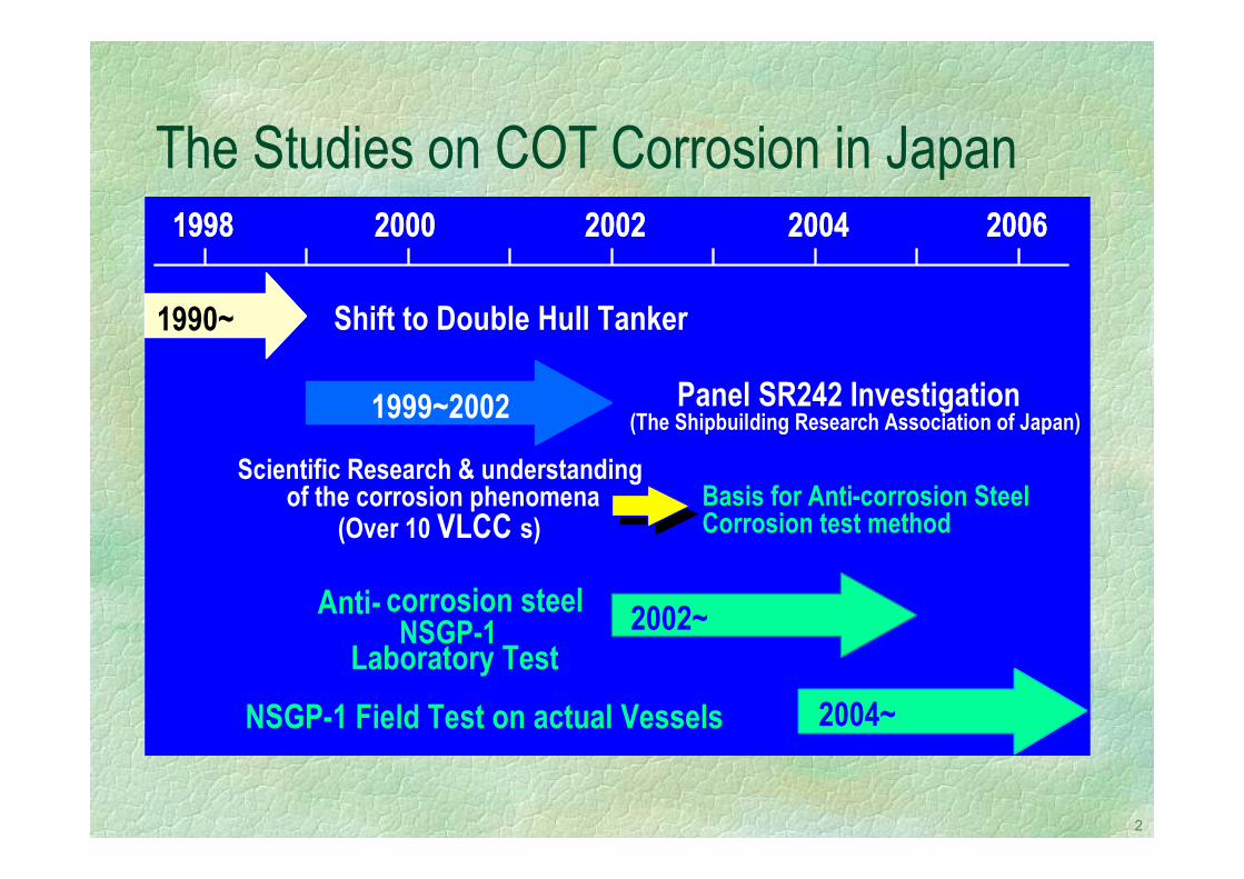
↑Inner Bottom
Inert Gas H2O H2S CO2
Crude Oil
Drain Water
Upper Deck PlateUpper Deck PlateUniform CorrosionUniform Corrosion
Inner Bottom PlateInner Bottom PlatePitting CorrosionPitting Corrosion
Upper Deck↓
Corrosion problems on COT of crude oil carriers
COT corrosion ・Upp.DK uniform corrosion・Pitting on bottom plate
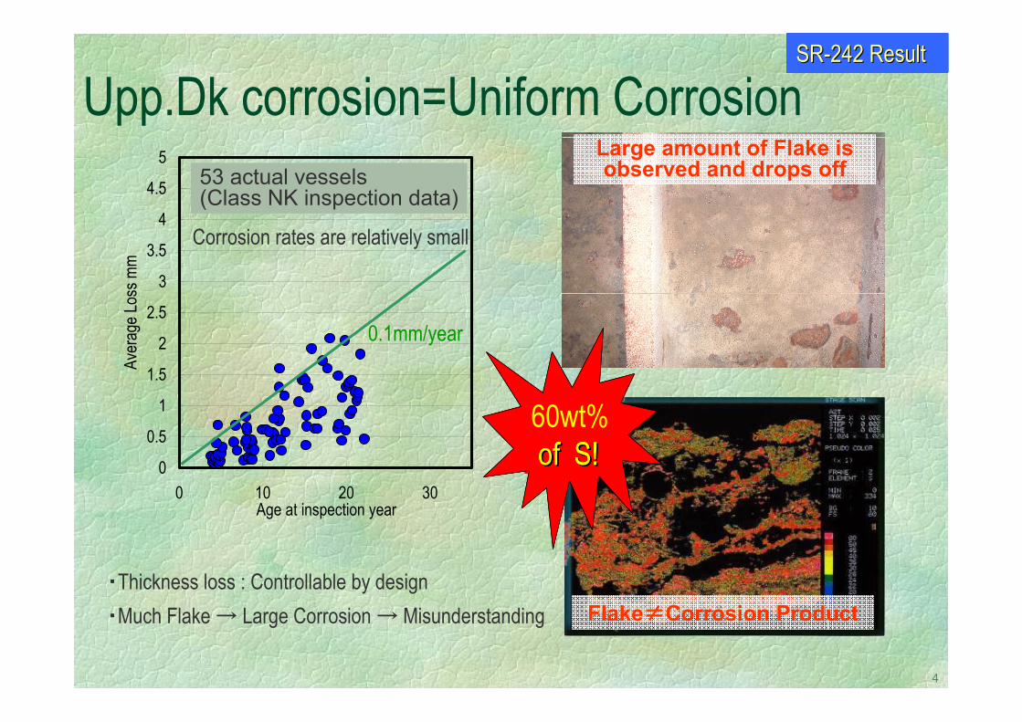
4
Upp.Dk corrosion=Uniform CorrosionLarge amount of Flake is observed and drops off
Flake≠Corrosion Product
60wt%60wt%60wt%
・Thickness loss : Controllable by design・Much Flake → Large Corrosion → Misunderstanding
SRSR--242 Result242 Result
0
0.5
1
1.5
2
2.5
3
3.5
4
4.5
5
0 10 20 30Age at inspection year
Aver
age L
oss m
m
60wt%
53 actual vessels(Class NK inspection data)
0.1mm/year
Corrosion rates are relatively small
of S!of S!of S!of S!
5
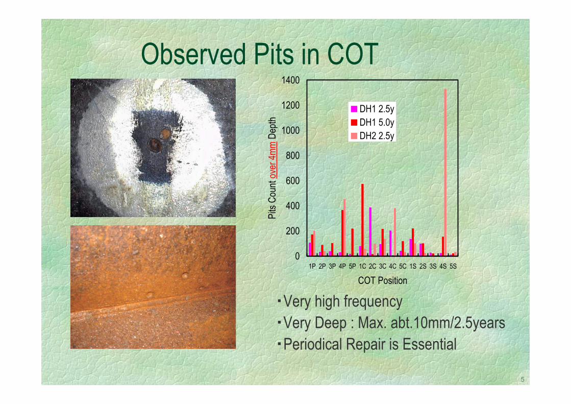
Observed Pits in COT
・Very high frequency・Very Deep : Max. abt.10mm/2.5years・Periodical Repair is Essential
0
200
400
600
800
1000
1200
1400
1P 2P 3P 4P 5P 1C 2C 3C 4C 5C 1S 2S 3S 4S 5S
COT PositionPi
ts Co
unt o
ver 4
mm D
epth
DH1 2.5yDH1 5.0yDH2 2.5y
6
How does the pitting corrosion start?
7
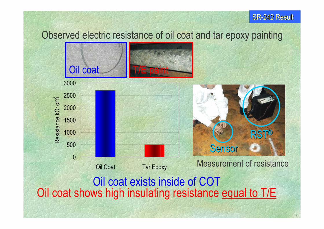
Observed electric resistance of oil coat and tar epoxy painting
Oil coat exists inside of COTOil coat shows high insulating resistance equal to T/E
0
500
1000
1500
2000
2500
3000
Oil Coat Tar Epoxy
Resis
tance
kΩ・ c
Oil coat T/E paint
SensorSensorRSTRST®®
Measurement of resistance
SRSR--242 Result242 Result
8
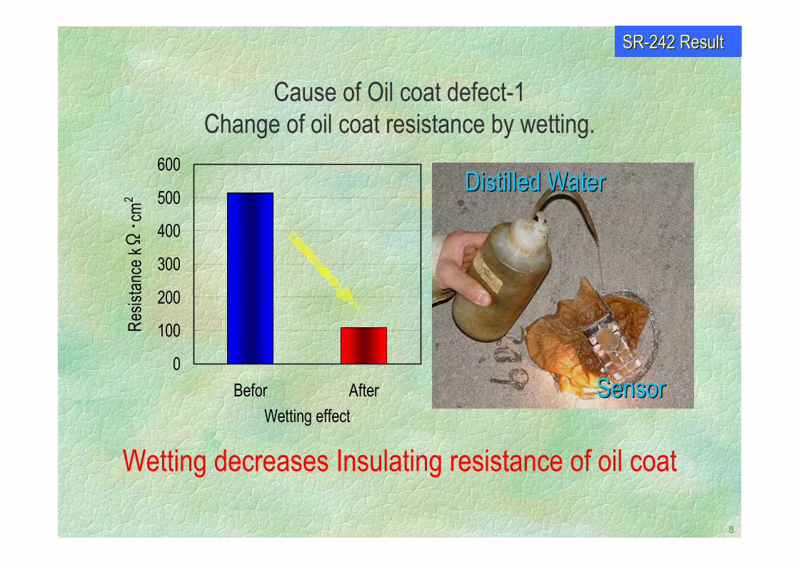
Cause of Oil coat defect-1 Change of oil coat resistance by wetting.
Wetting decreases Insulating resistance of oil coat
0
100
200
300
400
500
600
Befor AfterWetting effect
Resis
tance
kΩ・ c
m2
SensorSensor
Distilled WaterDistilled Water
SRSR--242 Result242 Result
9
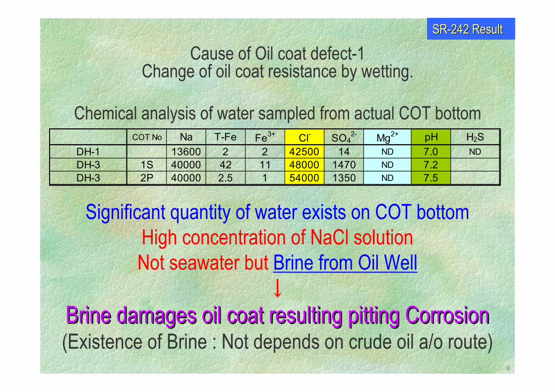
COT No Na T-Fe Fe3+ Cl- SO42- Mg2+ pH H2S
DH-1 13600 2 2 42500 14 ND 7.0 NDDH-3 1S 40000 42 11 48000 1470 ND 7.2DH-3 2P 40000 2.5 1 54000 1350 ND 7.5
Chemical analysis of water sampled from actual COT bottom
Significant quantity of water exists on COT bottomHigh concentration of NaCl solutionNot seawater but Brine from Oil Well
↓
Brine damages oil coat resulting pitting CorrosionBrine damages oil coat resulting pitting Corrosion(Existence of Brine : Not depends on crude oil a/o route)
Cause of Oil coat defect-1 Change of oil coat resistance by wetting.
SRSR--242 Result242 Result
10
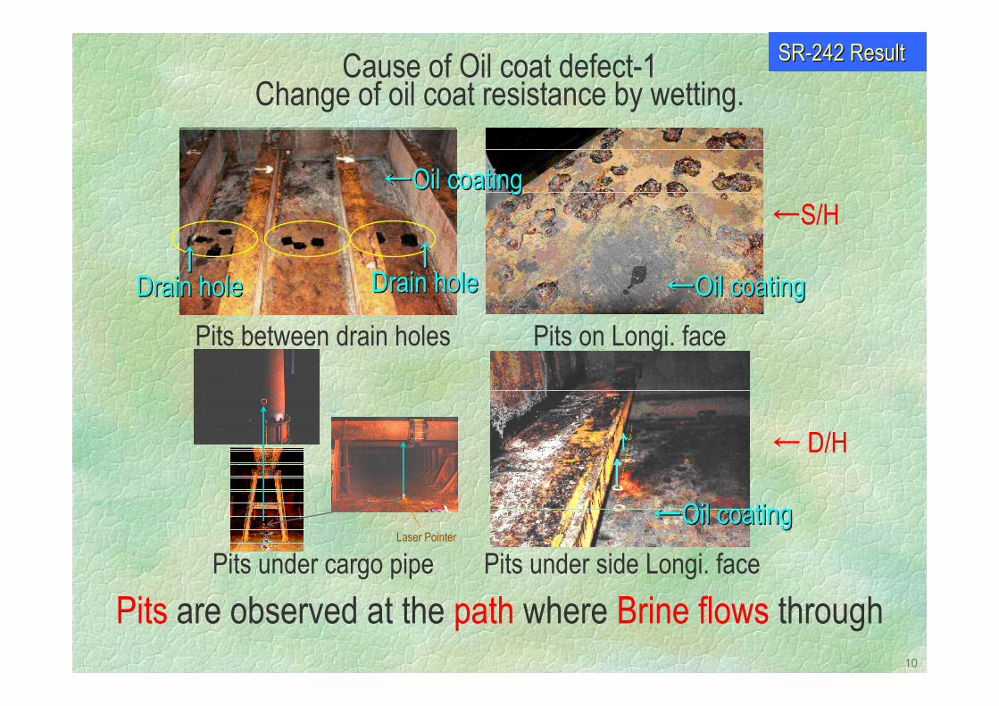
Laser Pointer
Pits on Longi. facePits between drain holes
Pits under cargo pipe Pits under side Longi. face
←S/H
← D/H
←←Oil coatingOil coating
←←Oil coatingOil coating
←←Oil coatingOil coating↑↑
Drain holeDrain hole↑↑
Drain holeDrain hole
Pits are observed at the path where Brine flows through
Cause of Oil coat defect-1 Change of oil coat resistance by wetting.
SRSR--242 Result242 Result
11
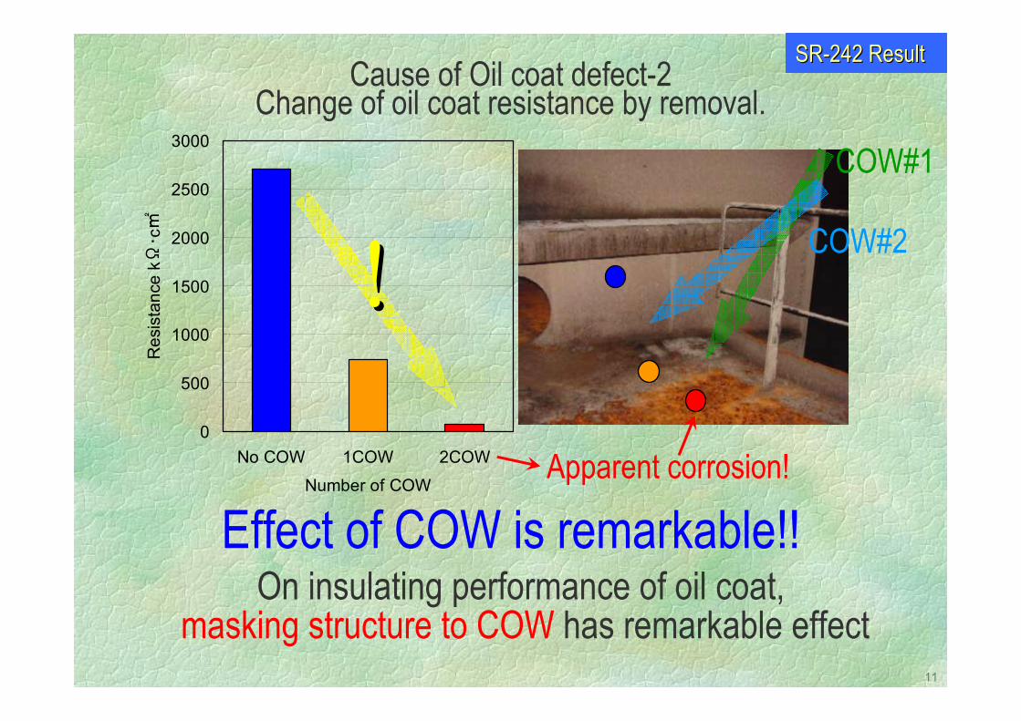
Effect of COW is remarkable!!On insulating performance of oil coat,
masking structure to COW has remarkable effect
0
500
1000
1500
2000
2500
3000
No COW 1COW 2COW
Number of COW
Res
ista
nce
kΩ・ c
!!COW#1
COW#2
Apparent corrosion!
Cause of Oil coat defect-2 Change of oil coat resistance by removal.
SRSR--242 Result242 Result

12
Detrimental Factors to Oil Coat defectDetrimental Factors to Oil Coat defect①① BrineBrine : by wetting: by wetting②② COWCOW : by removal: by removal
↓↓Both decreases insulating resistanceBoth decreases insulating resistance
↓↓Localized defect of oil coat results pitting corrosionLocalized defect of oil coat results pitting corrosion
Oil coat is not stable especially on D/H flat cargo tank topOil coat is not stable especially on D/H flat cargo tank top(compared to S/H bottom (compared to S/H bottom structure) structure)
Inner Bottom
Outer Bottom Outer Bottom
D/H S/HBottom Longi.Inner Bottom
Hidden ribNo shield for bottom Ribs : Shield for bottom
Inner Bottom
Outer Bottom Outer Bottom
D/H S/HBottom Longi.Inner Bottom
Hidden ribNo shield for bottom Ribs : Shield for bottom
13
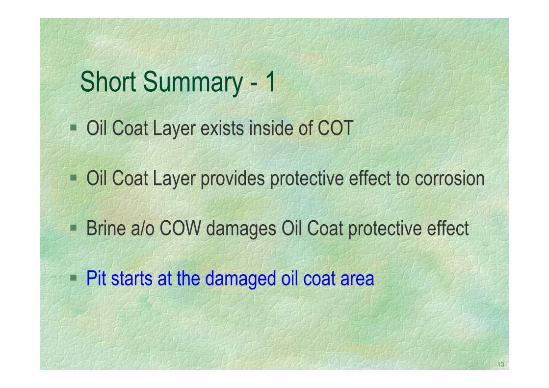
Short Summary - 1Oil Coat Layer exists inside of COT
Oil Coat Layer provides protective effect to corrosion
Brine a/o COW damages Oil Coat protective effect
Pit starts at the damaged oil coat area
14
How much is the pitting corrosion rate?
15
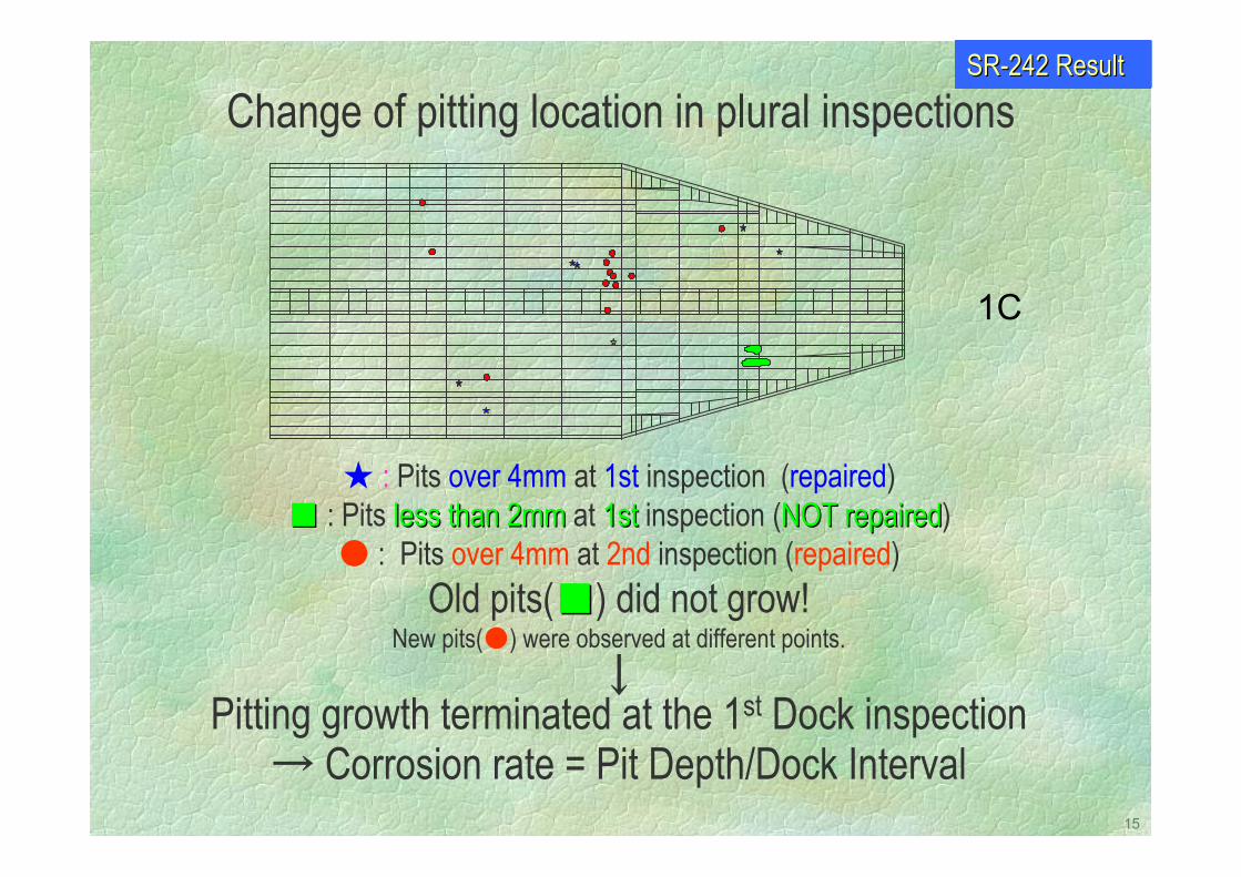
: Pits over 4mm at 1st inspection (repaired) : Pits less than 2mmless than 2mm at 1st1st inspection (NOT repairedNOT repaired)
: Pits over 4mm at 2nd inspection (repaired)Old pits() did not grow!
New pits() were observed at different points.↓
Pitting growth terminated at the 1st Dock inspection→ Corrosion rate = Pit Depth/Dock Interval
1C
Change of pitting location in plural inspectionsSRSR--242 Result242 Result
16
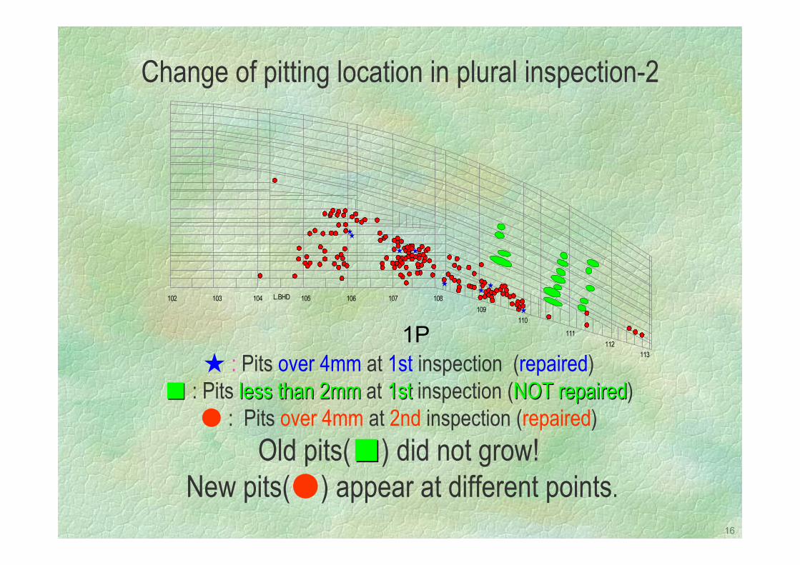
1P
Change of pitting location in plural inspection-2
102 103 104 105 106 107 108109
110
111112
113
L.BHD
: Pits over 4mm at 1st inspection (repaired) : Pits less than 2mmless than 2mm at 1st1st inspection (NOT repairedNOT repaired)
: Pits over 4mm at 2nd inspection (repaired)Old pits() did not grow!
New pits() appear at different points.
17
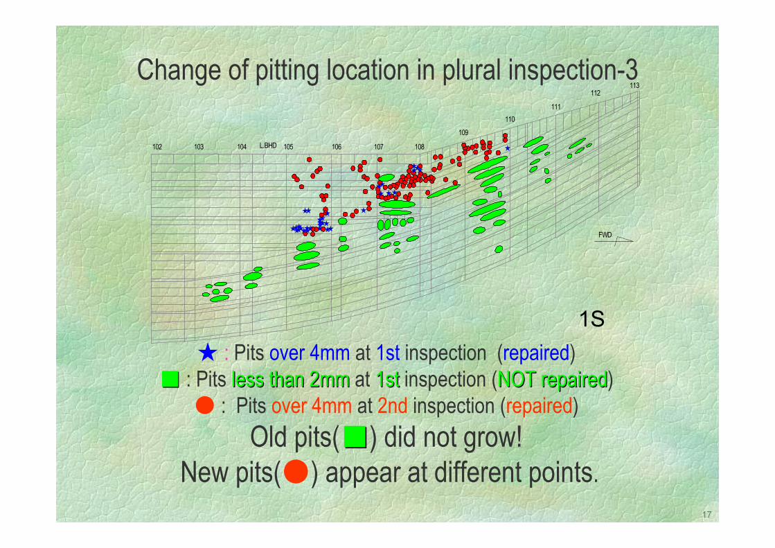
1S
Change of pitting location in plural inspection-3
102 103 104 105 106 107 108
109
110111
112113
L.BHD
FWD
: Pits over 4mm at 1st inspection (repaired) : Pits less than 2mmless than 2mm at 1st1st inspection (NOT repairedNOT repaired)
: Pits over 4mm at 2nd inspection (repaired)Old pits() did not grow!
New pits() appear at different points.
18
3C
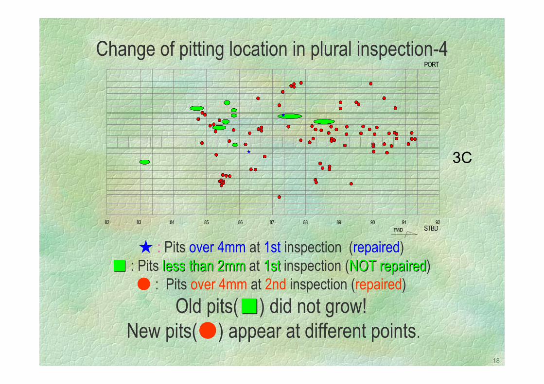
Change of pitting location in plural inspection-4
82 83 84 85 86 87 88 89 90 91 92
PORT
STBDFWD
: Pits over 4mm at 1st inspection (repaired) : Pits less than 2mmless than 2mm at 1st1st inspection (NOT repairedNOT repaired)
: Pits over 4mm at 2nd inspection (repaired)Old pits() did not grow!
New pits() appear at different points.
19
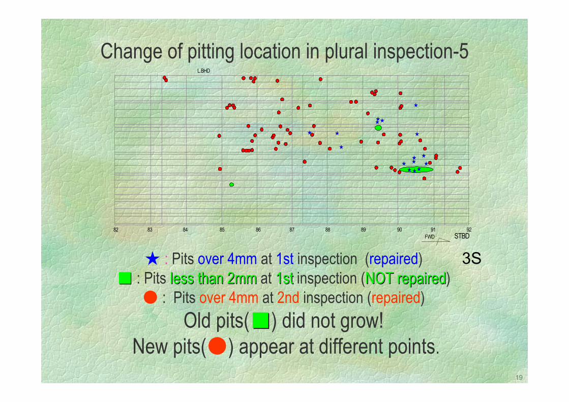
3S
Change of pitting location in plural inspection-5
82 83 84 85 86 87 88 89 90 91 92STBD
L.BHD
FWD
: Pits over 4mm at 1st inspection (repaired) : Pits less than 2mmless than 2mm at 1st1st inspection (NOT repairedNOT repaired)
: Pits over 4mm at 2nd inspection (repaired)Old pits() did not grow!
New pits() appear at different points.
20
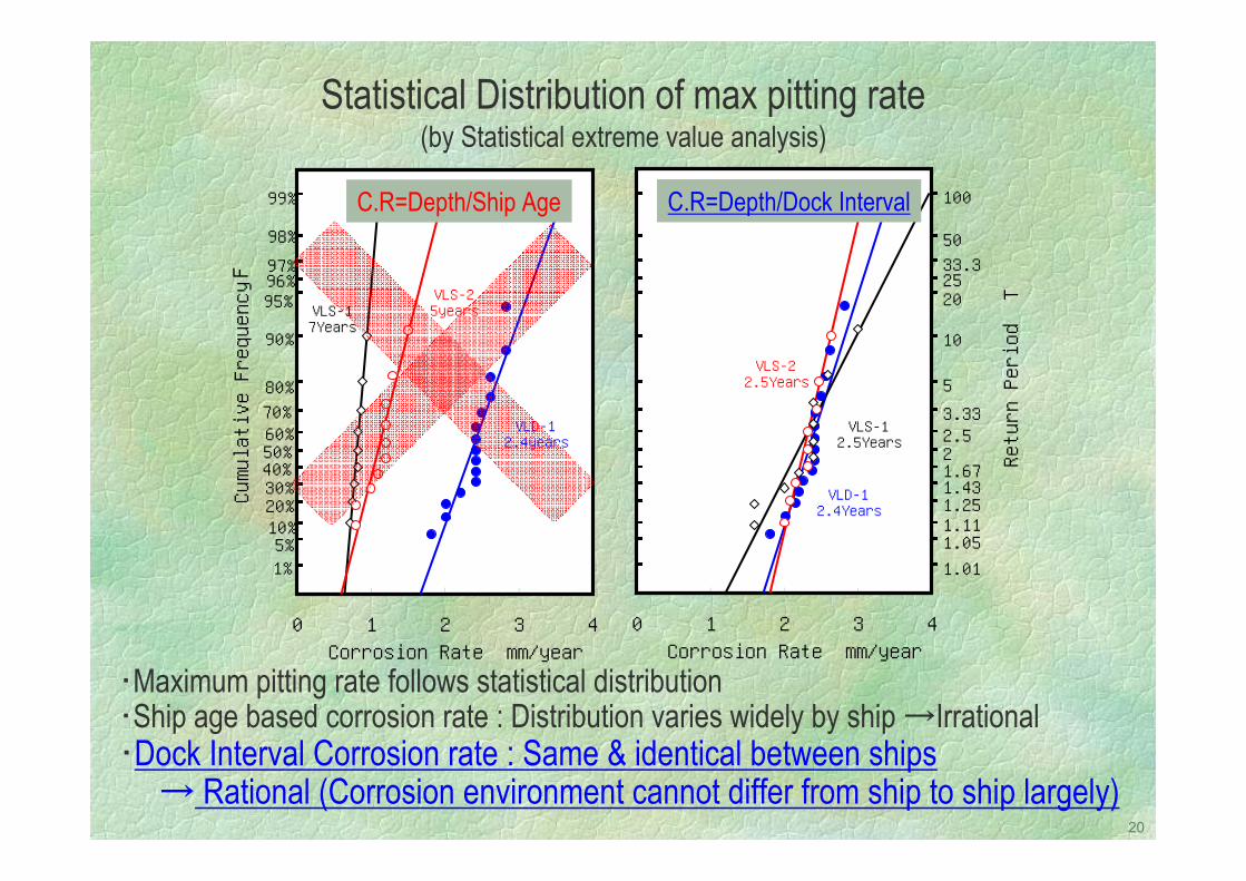
・Maximum pitting rate follows statistical distribution・Ship age based corrosion rate : Distribution varies widely by ship →Irrational・Dock Interval Corrosion rate : Same & identical between ships
→ Rational (Corrosion environment cannot differ from ship to ship largely)
1.011.051.111.251.431.6722.53.335
10
202533.350
100
0 1 2 3 4Corrosion Rate mm/year
Return Period T
VLD-12.4Years
VLS-12.5Years
VLS-22.5Years
F
99%
98%97%96%95%
90%
80%70%60%50%40%30%20%10%5%1%
0 1 2 3 4Corrosion Rate mm/year
Cumulative Frequency F
VLS-17Years
VLD-12.4years
VLS-25years
C.R=Depth/Dock IntervalC.R=Depth/Ship Age
Statistical Distribution of max pitting rate (by Statistical extreme value analysis)
21
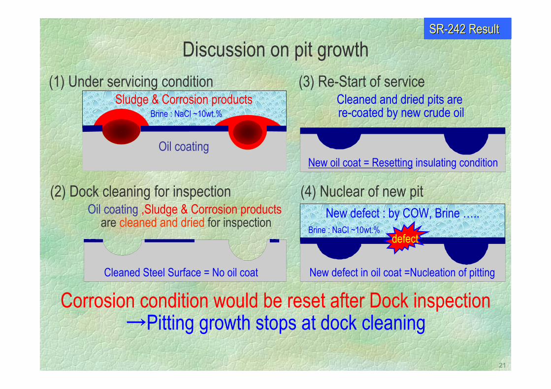
Brine : NaCl ~10wt.%
Corrosion condition would be reset after Dock inspection→Pitting growth stops at dock cleaning
(1) Under servicing condition
(2) Dock cleaning for inspection
(3) Re-Start of service
(4) Nuclear of new pit
Sludge & Corrosion products
Oil coating
Cleaned Steel Surface = No oil coat
Oil coating ,Sludge & Corrosion productsare cleaned and dried for inspection
Cleaned and dried pits are re-coated by new crude oil
New oil coat = Resetting insulating condition
defect
New defect in oil coat =Nucleation of pitting
New defect : by COW, Brine …..
Discussion on pit growth
Brine : NaCl ~10wt.%
SRSR--242 Result242 Result
22
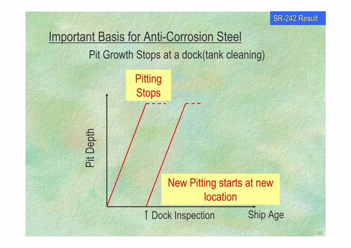
Pit Growth Stops at a dock(tank cleaning)
Pitting Stops
Pit D
epth
↑Dock Inspection Ship Age
New Pitting starts at new location
Important Basis for Anti-Corrosion SteelSRSR--242 Result242 Result
23
Short Summary - 2Pitting corrosion rate follows statistical distribution
Pitting stops at a dock (COT cleaning)
Pitting growth duration is dock interval
24
What is the pitting environment?
25
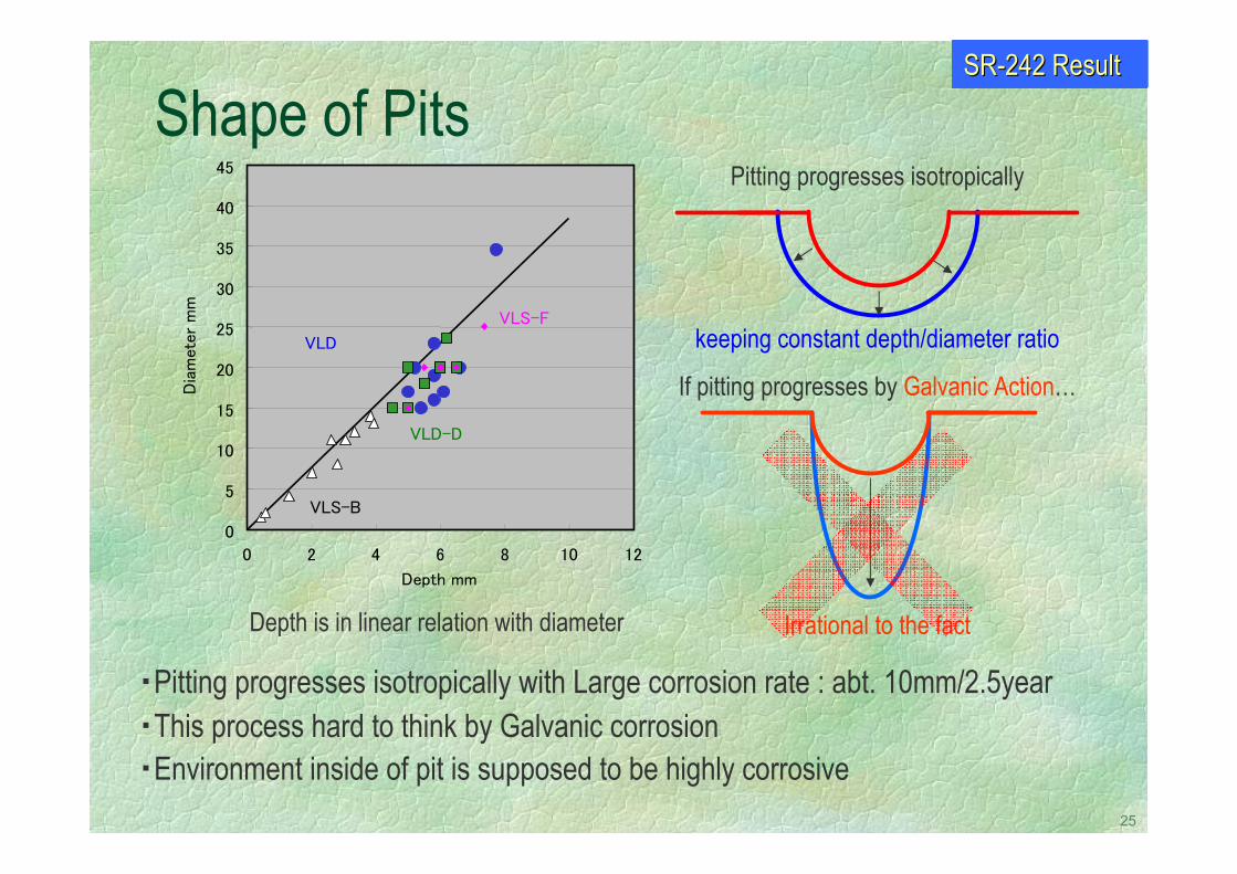
Pitting progresses isotropically
keeping constant depth/diameter ratio
If pitting progresses by Galvanic Action…
Irrational to the fact
Shape of Pits
Depth is in linear relation with diameter
0
5
10
15
20
25
30
35
40
45
0 2 4 6 8 10 12
Depth mm
Dia
mete
r m
m
VLS-B
VLD
VLD-D
VLS-F
・Pitting progresses isotropically with Large corrosion rate : abt. 10mm/2.5year・This process hard to think by Galvanic corrosion・Environment inside of pit is supposed to be highly corrosive
SRSR--242 Result242 Result
26
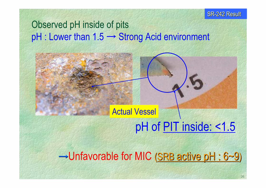
Observed pH inside of pitspH : Lower than 1.5 → Strong Acid environment
Actual Vessel
pH of PIT inside: <1.5
→→Unfavorable for MIC ((SRB SRB active pH : 6~9active pH : 6~9))
SRSR--242 Result242 Result
27
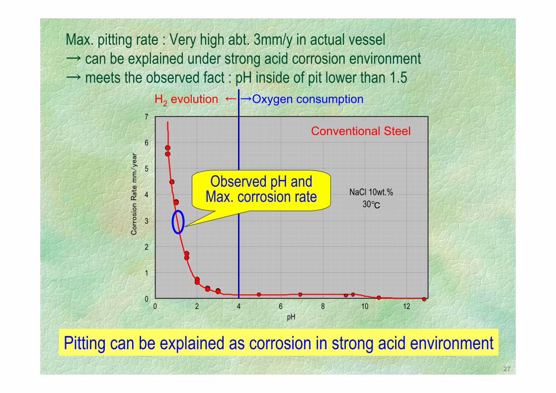
Max. pitting rate : Very high abt. 3mm/y in actual vessel→ can be explained under strong acid corrosion environment → meets the observed fact : pH inside of pit lower than 1.5
H2 evolution ← →Oxygen consumption
Pitting can be explained as corrosion in strong acid environment
0
1
2
3
4
5
6
7
0 2 4 6 8 10 12pH
Corr
osi
on R
ate m
m/ye
ar
NaCl 10wt.%30
Conventional Steel
Observed pH and Max. corrosion rate
28
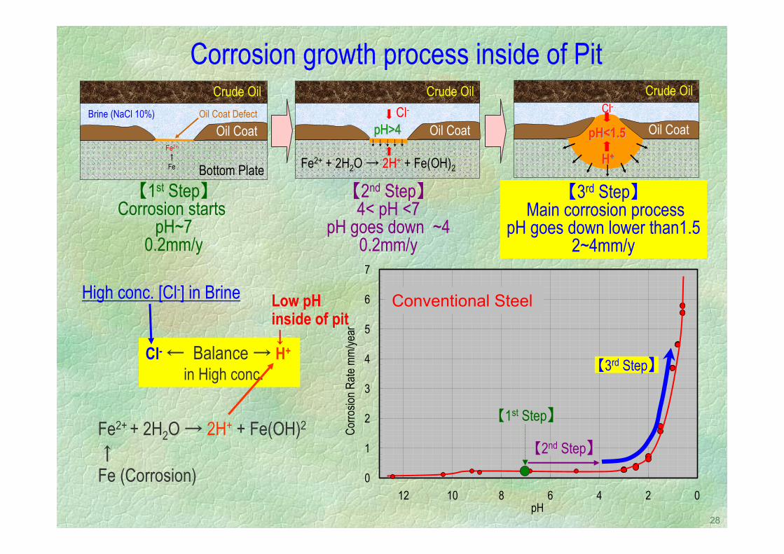
Corrosion growth process inside of Pit
【1st Step】Corrosion starts
pH~70.2mm/y
【2nd Step】4< pH <7
pH goes down ~40.2mm/y
【3rd Step】Main corrosion process
pH goes down lower than1.52~4mm/y
Crude Oil
Bottom Plate
Oil Coat DefectBrine (NaCl 10%)
Oil CoatFe2+
↑Fe
Crude Oil
Oil Coat
H+HH++
pH<1.5pH<1.5pH<1.5
Cl-Crude Oil
Oil CoatCl-
Fe2+ + 2H2O → 2H+ + Fe(OH)2
pH>4pH>4pH>4
0
1
2
3
4
5
6
7
024681012pH
Corro
sion R
ate m
m/ye
ar
【2nd Step】
【3rd Step】
【1st Step】
Conventional Steel
Fe2+ + 2H2O → 2H+ + Fe(OH)2
High conc. [Cl-] in Brine
↑Fe (Corrosion)
Cl- ← Balance → H+
in High conc.
Low pH inside of pit↓
29
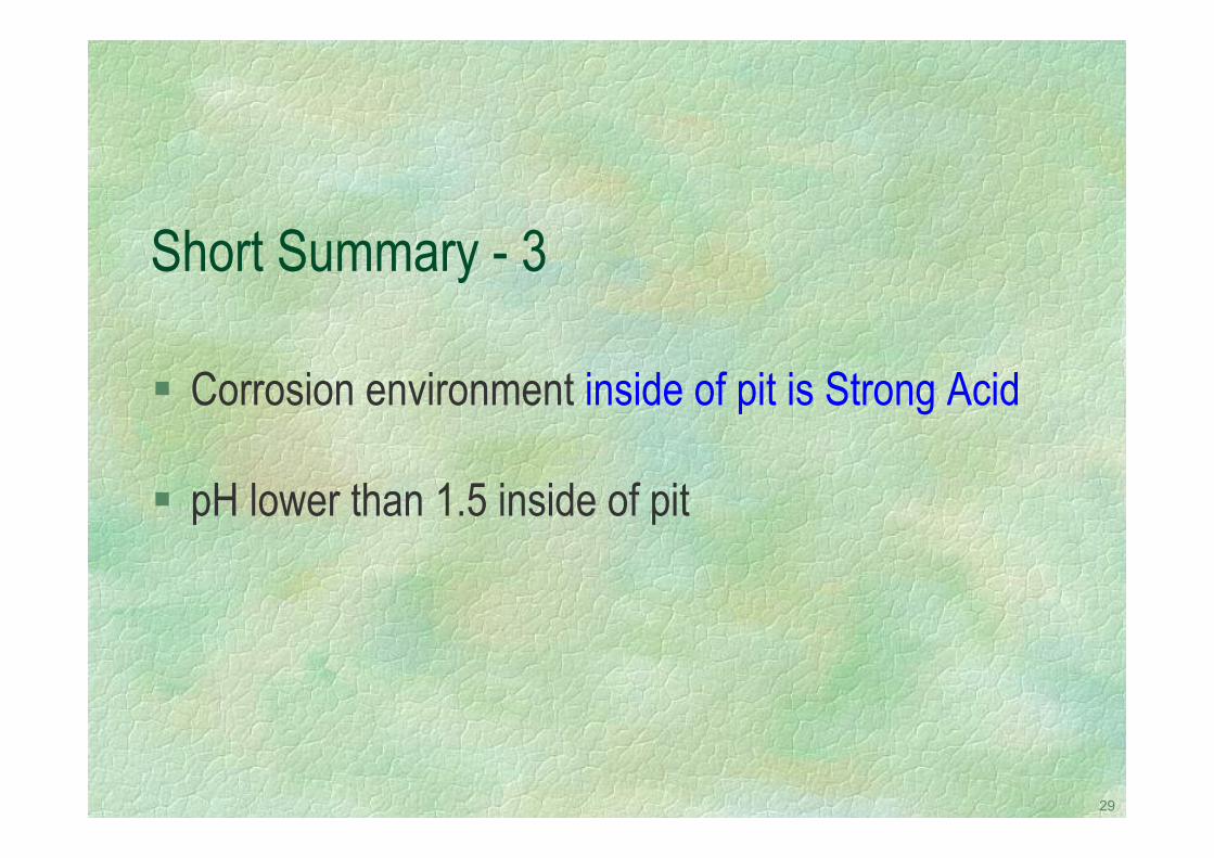
Short Summary - 3
Corrosion environment inside of pit is Strong Acid
pH lower than 1.5 inside of pit

30
Development target and result
31
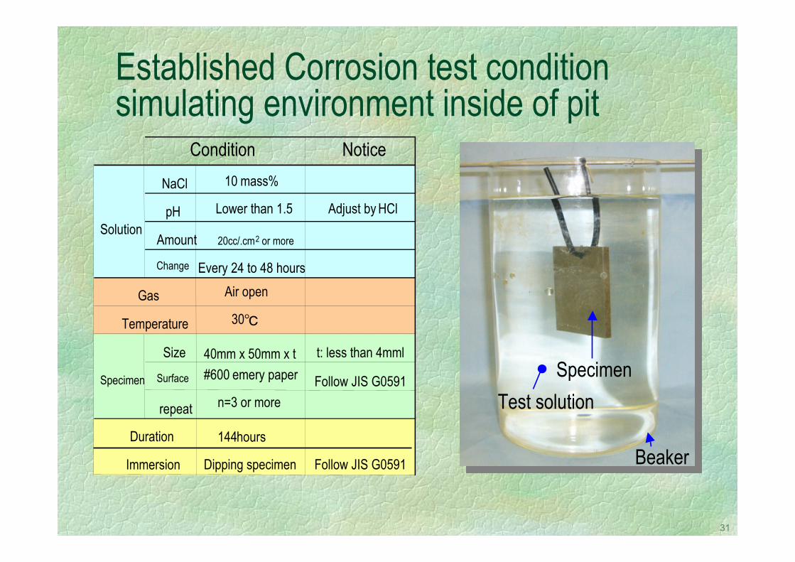
Established Corrosion test condition simulating environment inside of pit
Beaker
SpecimenTest solution
NoticeNaCl 10 mass%
pH Lower than 1.5 Adjust by HCl
Amount 20cc/.cm2 or more
Change Every 24 to 48 hoursAir open
30
Size 40mm x 50mm x t t: less than 4mml
Surface #600 emery paper Follow JIS G0591
repeat n=3 or more
144hours
Dipping specimen Follow JIS G0591Immersion
Gas
Temperature
Condition
Solution
Specimen
Duration
32
0.010.05
0.10.20.30.40.50.60.7
0.8
0.9
0.950.960.97
0.98
0.99
1.01
1.051.111.251.431.6722.53.33
5
10
202533.350
100
0 1 2 3 4Corrosion Rate mm/year
Cumu
lative
Fre
quen
cy F
Retur
n Per
iod TConventional
Steel
Average
15 COT
← Corresponds toLaboratorytest result
← Corresponds toOnboardMax. Depth
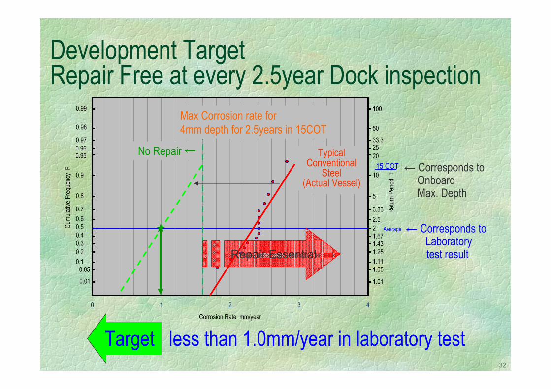
Development TargetRepair Free at every 2.5year Dock inspection
Repair Essential
Max Corrosion rate for4mm depth for 2.5years in 15COT
Target less than 1.0mm/year in laboratory test
No Repair ← TypicalConventional
Steel(Actual Vessel)
33
0
1
2
3
4
5
6
7
8
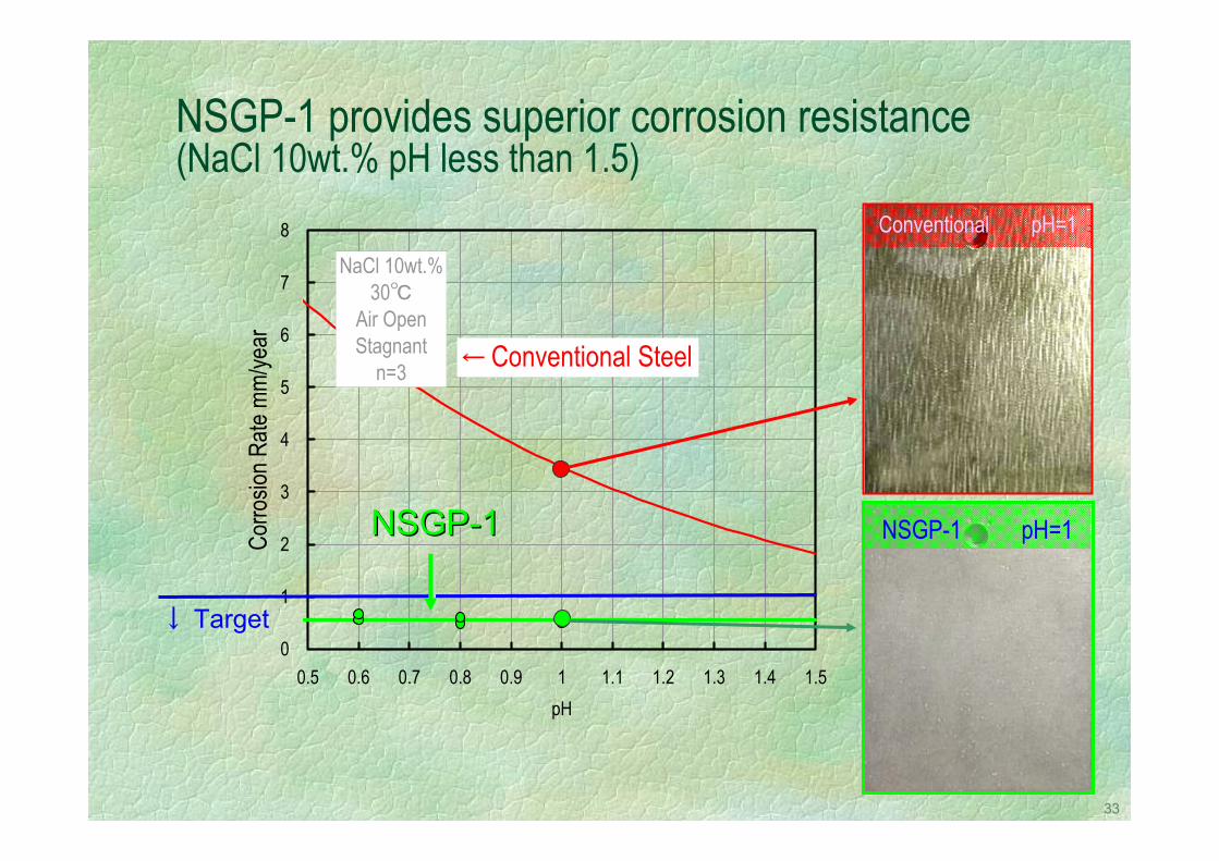
0.5 0.6 0.7 0.8 0.9 1 1.1 1.2 1.3 1.4 1.5pH
Corro
sion R
ate m
m/ye
ar
← Conventional Steel
NaCl 10wt.%30
Air OpenStagnant
n=3
NSGP-1 provides superior corrosion resistance (NaCl 10wt.% pH less than 1.5)
Conventional pH=1
NSGP-1 pH=1NSGP-1NSGPNSGP--11
↓ Target
34
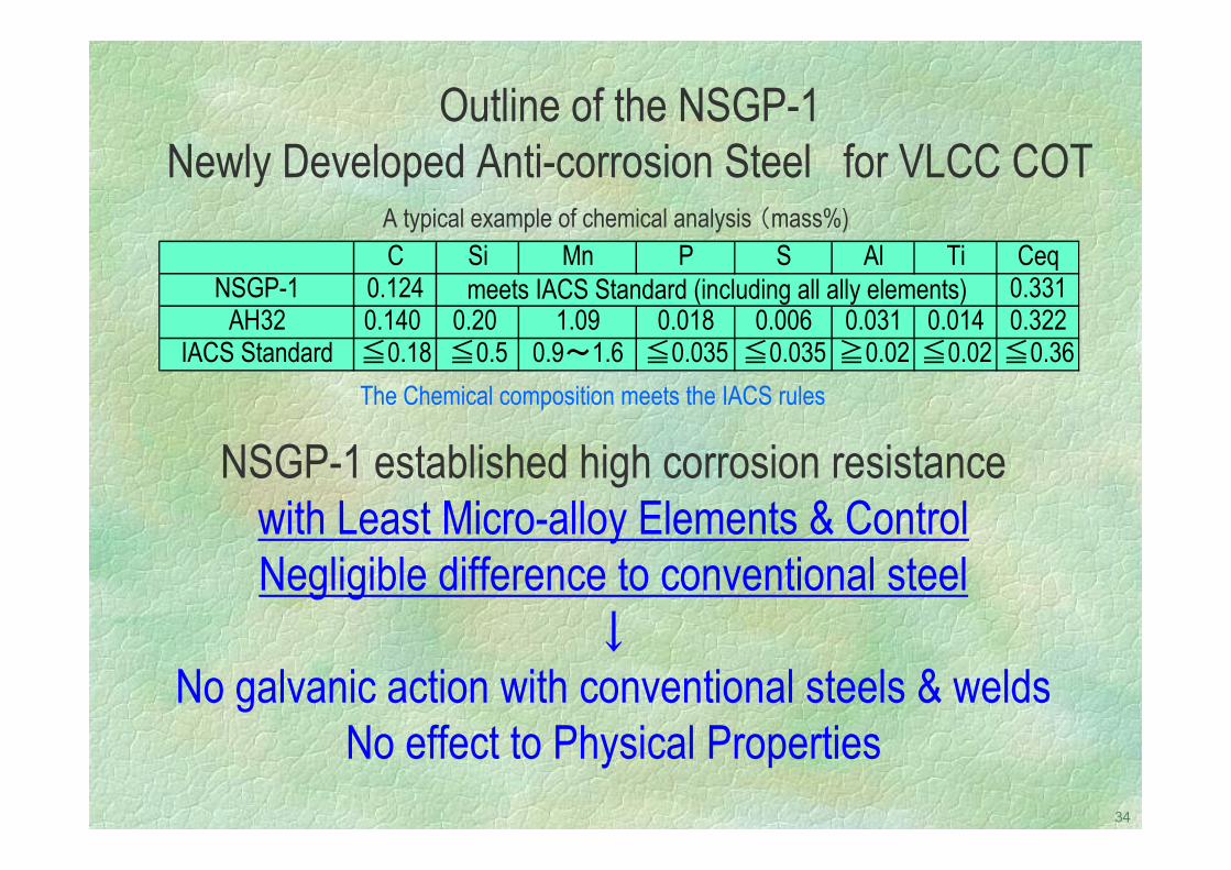
Outline of the NSGP-1Newly Developed Anti-corrosion Steel for VLCC COT
A typical example of chemical analysis (mass%)
NSGP-1 established high corrosion resistancewith Least Micro-alloy Elements & ControlNegligible difference to conventional steel
↓No galvanic action with conventional steels & welds
No effect to Physical Properties
C Si Mn P S Al Ti CeqNSGP-1 0.124 0.331
AH32 0.140 0.20 1.09 0.018 0.006 0.031 0.014 0.322IACS Standard ≦0.18 ≦0.5 0.9~1.6 ≦0.035 ≦0.035 ≧0.02 ≦0.02 ≦0.36
meets IACS Standard (including all ally elements)
The Chemical composition meets the IACS rules
35
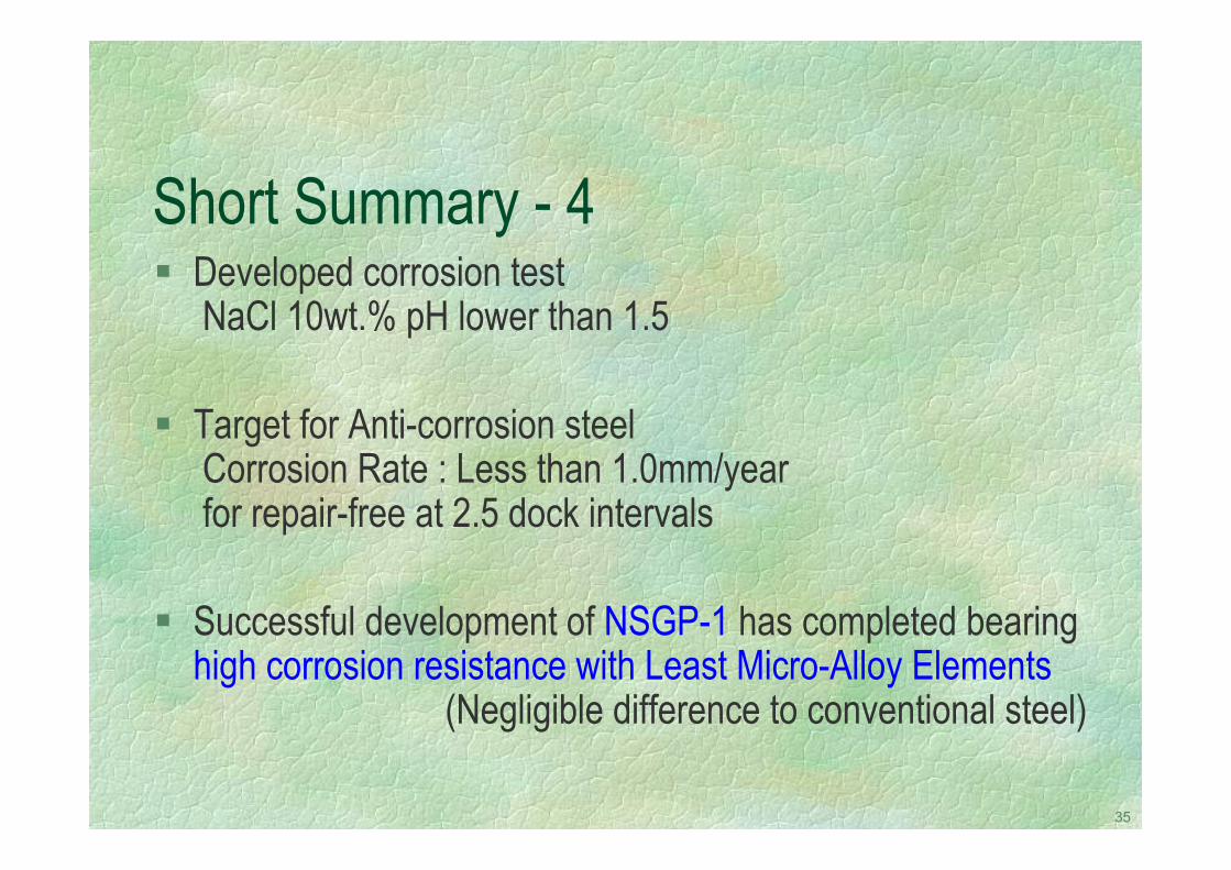
Short Summary - 4Developed corrosion test NaCl 10wt.% pH lower than 1.5
Target for Anti-corrosion steelCorrosion Rate : Less than 1.0mm/yearfor repair-free at 2.5 dock intervals
Successful development of NSGP-1 has completed bearing high corrosion resistance with Least Micro-Alloy Elements
(Negligible difference to conventional steel)
36
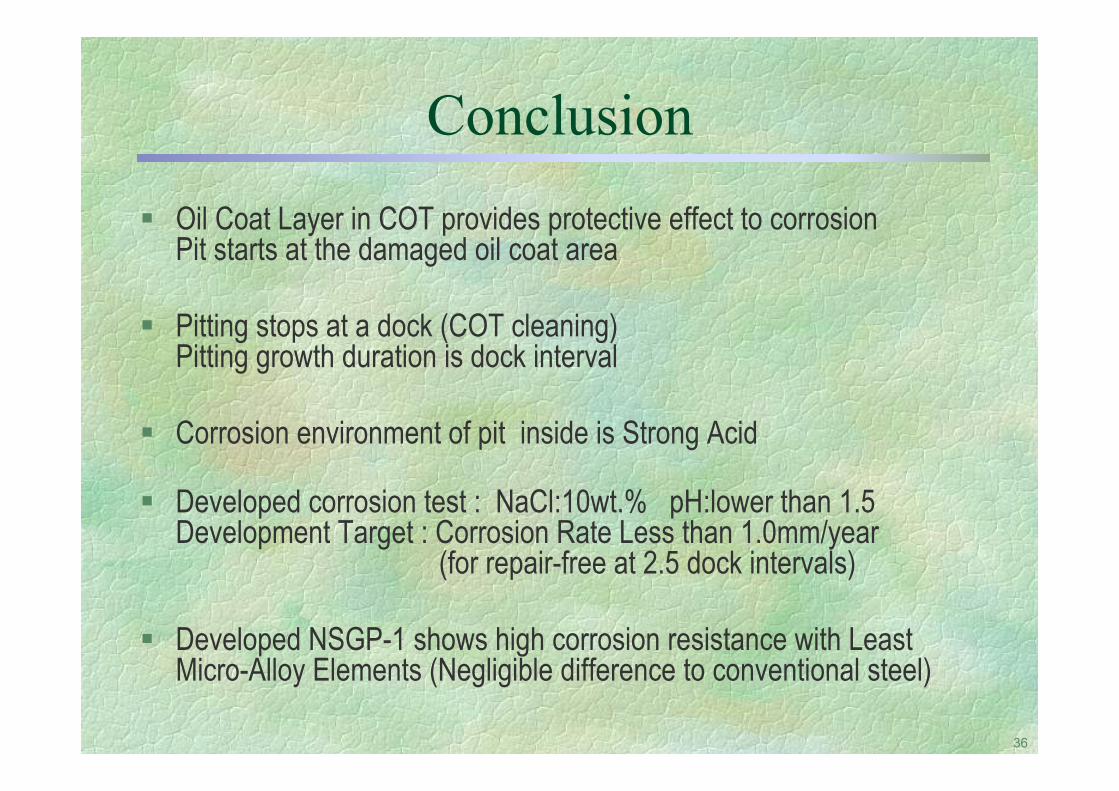
ConclusionOil Coat Layer in COT provides protective effect to corrosionPit starts at the damaged oil coat area
Pitting stops at a dock (COT cleaning)Pitting growth duration is dock interval
Corrosion environment of pit inside is Strong Acid
Developed corrosion test : NaCl:10wt.% pH:lower than 1.5Development Target : Corrosion Rate Less than 1.0mm/year
(for repair-free at 2.5 dock intervals)
Developed NSGP-1 shows high corrosion resistance with Least Micro-Alloy Elements (Negligible difference to conventional steel)


![DEVELOPMENT OF NEW ANTI-CORROSION STEEL FOR COTS OF CRUDE OIL … · Crude Oil type Gas [vol%] The inside of the COT is washed and cleaned in advance in order to carry out the survey](https://img.pdfslide.net/doc/110x75/5eb1bdaea62b6645f4652fb1/development-of-new-anti-corrosion-steel-for-cots-of-crude-oil-crude-oil-type-gas.jpg)