Embed Size (px)
Citation preview

Development of Optimum Design Method for the Heat Recovery Ground
Source Heat Pump System
12th IEA Heat Pump Conference May 18th, 2017, Rotterdam, Netherland
Takao KATSURAFaculty of Engineering, Graduate School of Hokkaido
University

Today’s Contents
1) Design process of HR-GSHP system and basic concept of the design2) Determination method of the thermal load of each GSHP unit in the HR-GSHP system by using optimization method
1) Outlines of subject building and calculation condition2) Determined thermal load of the HR-GSHP system3) Temperature variation of heat carrier fluid in the HR-GSHP system4) Installation effect of the HR-GSHP system
(2) Design method for the HR-GSHP system by using optimization method
1
(3) Feasibility study of installing the HR-GSHP system using the design method
T. Katsura, K. Nagano et al, 12th IEA HPC, 2017-5-18, Rotterdam, Netherland
(1) What is the heat recovery ground source heat pump (HR-GSHP) system ?1) Outlines and advantages2) Applications
Introduction 2
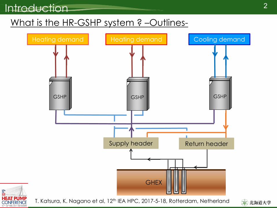
What is the HR-GSHP system ? –Outlines-
T. Katsura, K. Nagano et al, 12th IEA HPC, 2017-5-18, Rotterdam, Netherland
Heating demand Cooling demandHeating demand
Return headerSupply header
GHEX

Introduction 3
What is the HR-GSHP system ? –Application-
T. Katsura, K. Nagano et al, 12th IEA HPC, 2017-5-18, Rotterdam, Netherland
Large complex building
Retail storeRetail store
Restaurant
Retail storeRetail store
OfficeOfficeOfficeOfficeOffice
HotelHotelHotelHotel
Restaurant
Example of hourly thermal load in annual
Hotel

Introduction 4
What is the HR-GSHP system ? –Application-
T. Katsura, K. Nagano et al, 12th IEA HPC, 2017-5-18, Rotterdam, Netherland
Large complex building

Introduction 5
What is the HR-GSHP system ? –Application-
T. Katsura, K. Nagano et al, 12th IEA HPC, 2017-5-18, Rotterdam, Netherland
Food productive processCold
storageCasting
Seasoning Drying Vaporing Cooling Packing HeatingSterilization Cooling Shipment
Cold water
Cold water
Vapor
Boiler
GSHP
GHEX
GSHP GSHP
Tap water
Pre-heated water

Introduction 6
What is the HR-GSHP system ? –Application-
T. Katsura, K. Nagano et al, 12th IEA HPC, 2017-5-18, Rotterdam, Netherland
Thermal grid system

7
Design method for the HR-GSHP system by using optimization method

8Design process of HR-GSHP system and basic concept of the design
Concept diagram of HR-GSHP system
Basic design concept
2. The GSHP’s total heat load are maximized by using the two heat recovery effects
1. The GSHP units are operated by priority
T. Katsura, K. Nagano et al, 12th IEA HPC, 2017-5-18, Rotterdam, Netherland

9Determination method of the thermal load of each GSHP unit
T. Katsura, K. Nagano et al, 12th IEA HPC, 2017-5-18, Rotterdam, Netherland
Flow of design method
Example of Qghr, i and Qgcr, j

10Determination method of the thermal load of each GSHP unit
T. Katsura, K. Nagano et al, 12th IEA HPC, 2017-5-18, Rotterdam, Netherland
Flow of design method
Example of hourly thermal load (top)and heat extraction (bottom)

11Determination method of the thermal load of each GSHP unit
T. Katsura, K. Nagano et al, 12th IEA HPC, 2017-5-18, Rotterdam, Netherland
Flow of design method
Simplifying hourly heat extraction

12Determination method of the thermal load of each GSHP unit
T. Katsura, K. Nagano et al, 12th IEA HPC, 2017-5-18, Rotterdam, Netherland
Optimizing the thermal load of each GSHP unit Objective function: 𝐽" = ∑ 𝑄&'(
)*+,)-. + ∑ 𝑄&'0
)*+,)-.
Evaluation variables: 𝑄234567, 𝑄284567Constrains:A. 0 < 𝑄234567 ≤ 𝑄23456𝑄23456 = 𝑞=23𝐿2Δ𝑇2448A×1000
B. 0 < 𝑄284567 ≤ 𝑄28456𝑄28456 = 𝑞=28𝐿2Δ𝑇24456×1000
C. D.E≤
∑ ∑ "FG*,I+IJG
K*+,KJG
∑ ∑ "FGI,I+IJG
K*+,KJG
≤ .ED
Maximized
Here,
Δ𝑇2448A : Maximum temperature variation for heat extraction [oC] Δ𝑇24456 : Maximum temperature variation for heat injection [oC]
𝑄23456
: Total length of GHEX [m]
: Maximum value of GHEX’s heat extraction Qpe [kW]𝑄28456
𝐿2
: Maximum value of GHEX’s heat injection Qpi [kW]
: Heat extraction rate [W/m/K] (Explained later)𝑞=23, 𝑞=28
Constrains by giving the total length of GHEX, heat extraction rate 𝑞=23,𝑞=28 and allowable temperatures, T1inmax and T1inmin
Constrains of heat balance between heat extraction and heat injection
The genetic algorithm (GA) is applied for the optimization method because the objective function lacked smoothness and was nonlinear according to the evaluation variables

13Determination method of the thermal load of each GSHP unit Optimizing the thermal load of each GSHP unit Example of changing the evaluation variable and objective function
T. Katsura, K. Nagano et al, 12th IEA HPC, 2017-5-18, Rotterdam, Netherland
𝑄28456
𝑄&.
𝑄284567
𝑄23456𝑄234567
𝑄&. > 𝑄28456
𝑄234567
𝑄284567
𝑄&. ≤ 𝑄28456

14
T. Katsura, K. Nagano et al, 12th IEA HPC, 2017-5-18, Rotterdam, Netherland
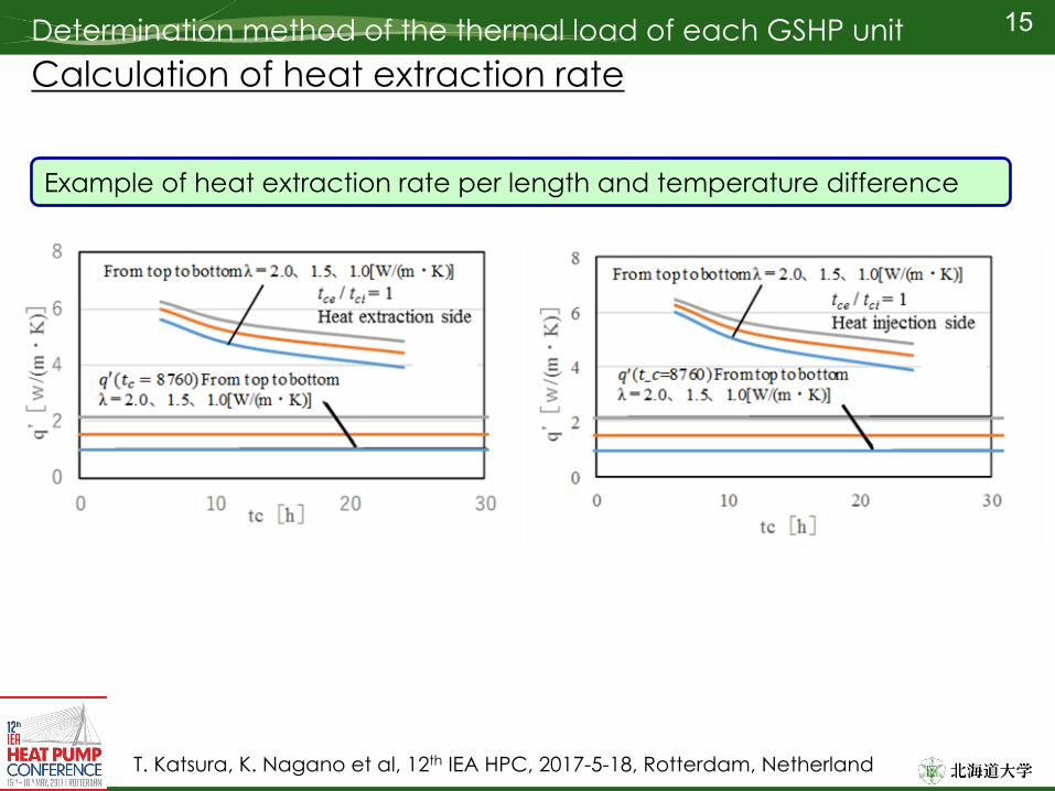
Calculation of heat extraction rateDetermination method of the thermal load of each GSHP unit
Example of hourly heat extraction
Example of temperature variation of heat carrier fluid
Elapsed time [h]T
[o C]
𝑄28
𝑄23
Δ𝑇2448A
Δ𝑇24456
Heat extraction rate per length and temperature difference 𝑞′ [W/m/K]
𝑞′ =𝑄2/𝐿2Δ𝑇24
Elapsed time [h]
15
T. Katsura, K. Nagano et al, 12th IEA HPC, 2017-5-18, Rotterdam, Netherland
Calculation of heat extraction rateDetermination method of the thermal load of each GSHP unit
Example of heat extraction rate per length and temperature difference

16
Feasibility study of installing the HR-GSHP system using the design method

17Outlines of subject building and calculation condition
T. Katsura, K. Nagano et al, 12th IEA HPC, 2017-5-18, Rotterdam, Netherland
Retail storeRetail store
Restaurant
Retail storeRetail store
OfficeOfficeOfficeOfficeOffice
HotelHotelHotelHotel
Restaurant
Example of hourly thermal load in annual
Hotel
Outlines of subject building and thermal loadLarge complex building

18Outlines of subject building and calculation condition
T. Katsura, K. Nagano et al, 12th IEA HPC, 2017-5-18, Rotterdam, Netherland
Outlines of HR-GSHP system and calculation condition
Heatingcapacity : 2,000 kW
Coolingcapacity : 1,200 kW
Single U-tube GHEXDepth: 100 m, 72 boreholes
Condition of soil propertyInitial ground temperature : 16.5 oCHeat capacity : 3,000 kJ/m3/KEffective thermal conductivity : 1.5 W/m/K

19Determined thermal load of the HR-GSHP system
T. Katsura, K. Nagano et al, 12th IEA HPC, 2017-5-18, Rotterdam, Netherland
Comparison of thermal loads with the conventional GSHP systemThermal load of the HR-GSHP system
Thermal load of the conventional GSHP system
Heating load for HR-GSHP system
Cooling load for HR-GSHP system
Heating load for HR-GSHP system
Cooling load for HR-GSHP system
Heating load for HR-GSHP system
Cooling load for HR-GSHP system
Heating load for HR-GSHP system
Cooling load for HR-GSHP system
Total thermal loadHeating load : 5,442 MWh Cooling load : 3,955 MWh
Total thermal loadHeating load : 1,303 MWh Cooling load : 883 MWh
4.3 times

20Temperature variation of heat carrier fluid
T. Katsura, K. Nagano et al, 12th IEA HPC, 2017-5-18, Rotterdam, Netherland
Comparison of temperature variations with the conventional GSHP system
Temperature variation of T1in in the HR-GSHP system
Temperature variation of T1in in the conventional GSHP system

21Installation effect of the HR-GSHP system
T. Katsura, K. Nagano et al, 12th IEA HPC, 2017-5-18, Rotterdam, Netherland
Comparison of thermal loads and COPs with the conventional GSHP system

22Summary(1) A design method applying the optimization method for the HR-GSHP system was introduced. By applying the design method, the total heating and cooling loads of each GSHP unit in the HR-GSHP system were maximized in response to an arbitrarily set GHEX total length.
(2) Assuming that an HR-GSHP system is installed in a large scale complex building, the hourly heating and cooling loads of each GSHP unit were determined using the optimum design method. The results showed that the HR-GSHP could cover approximately 4.3 times of the heat load compared to a conventional GSHP system.
T. Katsura, K. Nagano et al, 12th IEA HPC, 2017-5-18, Rotterdam, Netherland
(3) The average COPs for the HR-GSHP system were 4.6 for heating and 10.3 for cooling. Therefore, the HR-GSHP system also has the advantage of COP compared to the conventional GSHP system.

23
Thank you for your attention

Introduction 24
T. Katsura, K. Nagano et al, 12th IEA HPC, 2017-5-18, Rotterdam, Netherland
Ground source heat pump (GSHP) systems have gained attention in Japan since ground thermal energy was defined as one of the renewable energies in 2009. However in Japan there are few examples of large GSHP system with a total heating or cooling capacity of more than 500 kW.
Heat recovery ground source heat pump (HR-GSHP) system have the potential to promote the installation of large GSHP system.

Introduction 25
What is the HR-GSHP system ? –Advantages-
T. Katsura, K. Nagano et al, 12th IEA HPC, 2017-5-18, Rotterdam, Netherland
Direct heat recovery effect
Example of hourly thermal load
Heating load
Cooling load
Example of hourly heat extraction rate
Eliminated heat extraction (Blue)
Eliminated heat injection (Red)
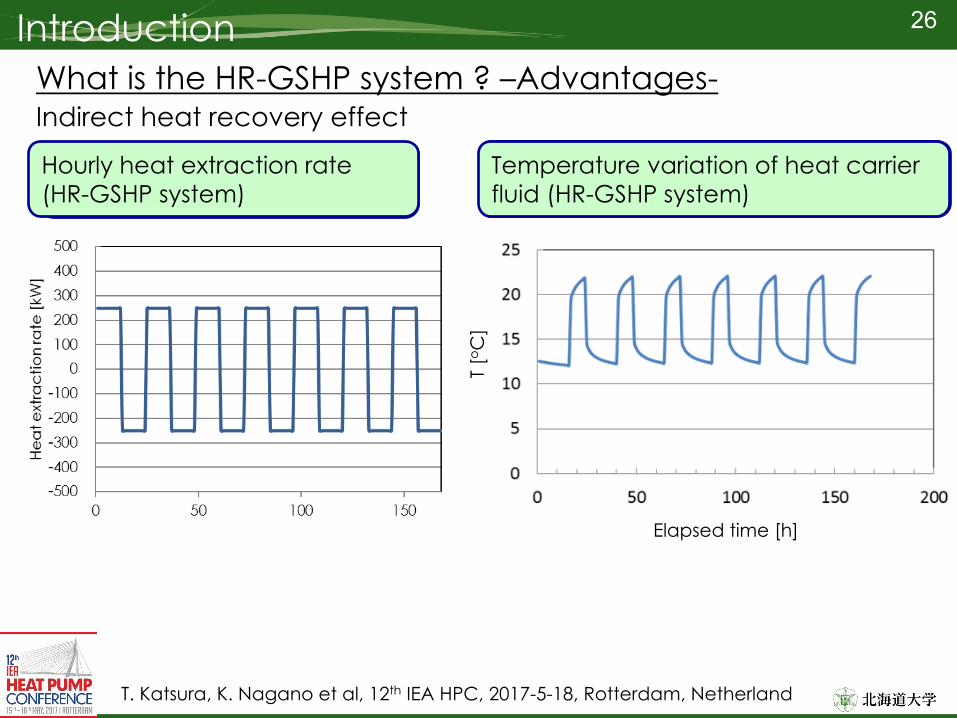
Introduction 26
What is the HR-GSHP system ? –Advantages-
T. Katsura, K. Nagano et al, 12th IEA HPC, 2017-5-18, Rotterdam, Netherland
Indirect heat recovery effect
Temperature variation of heat carrier fluid (Conventional GSHP system)
Hourly heat extraction(Conventional GSHP system)
Hourly heat extraction rate(HR-GSHP system)
Temperature variation of heat carrier fluid (HR-GSHP system)
Elapsed time [h]
T [o C
]

Design process of HR-GSHP system and basic concept of the design 27
Necessity of optimization method for design process
T. Katsura, K. Nagano et al, 12th IEA HPC, 2017-5-18, Rotterdam, Netherland
Diagram of design process for the conventional GSHP system
Design tool for the GSHP system
Introduced HPC2005 Las Vegas
However, it is required tohandle the heat loads of several types of heat pumps.
The number of variable increases
The optimization method is required to determine the heat loads
Diagram of design process for the HR-GSHP system

28Installation effect of the HR-GSHP system
T. Katsura, K. Nagano et al, 12th IEA HPC, 2017-5-18, Rotterdam, Netherland
Comparison of electric power consumption with the conventional GSHP system
40 %

29Design process of HR-GSHP system and basic concept of the design
Concept diagram of HR-GSHP system
We assume the followingsin the modeling
2. The total heat load Q2,iis covered not only by the GSHP in HR-GSHP system but also by other heat source systems
1. Heat gain and heat loss in the piping between the heat pump units and GHEXs
T. Katsura, K. Nagano et al, 12th IEA HPC, 2017-5-18, Rotterdam, Netherland

30Modeling of the HR-GSHP system
Concept diagram of HR-GSHP system
We assume the followingsin the modeling
2. The total heat load Q2,iis covered not only by the GSHP in HR-GSHP system but also by other heat source systems
1. Heat gain and heat loss in the piping between the heat pump units and GHEXs
T. Katsura, K. Nagano et al, 12th IEA HPC, 2017-5-18, Rotterdam, Netherland

31Modeling of the HR-GSHP system
Concept diagram of HR-GSHP system (1) Calculation of total thermal load of GSHP units
(If the heat pump unit i=1 supplies heating, the heating load of the heat pump unit i=1 is added to the heating side)
Example of hourly Qg2h, Qg2c
Qg2h(Qg2)
Qg2c(Negative side of Qg2)
𝑄&'( =O𝑄&'(,8
A
8-.
𝑄&'0 =O𝑄&'0,8
A
8-.
HeatingloadCoolingload
T. Katsura, K. Nagano et al, 12th IEA HPC, 2017-5-18, Rotterdam, Netherland
Q [k
W]

32Modeling of the HR-GSHP system
Concept diagram of HR-GSHP system (2)Calculation of total heat extraction rate of GSHP units
𝑄&.3,8 = 𝑄&'(,8 − 𝑄&'(,8/𝐶𝑂𝑃(,8Here,
𝑄&.8,8 = 𝑄&'0,8 − 𝑄&'0,8/𝐶𝑂𝑃0,8
Example of hourly Qg1e, Qg1i
Qg1e (Qg1)
Qg1i (Negative side of Qg1)
T. Katsura, K. Nagano et al, 12th IEA HPC, 2017-5-18, Rotterdam, Netherland
𝑄&.3 =O𝑄&.3,8
A
8-.
𝑄&.8 =O𝑄&.T,8
A
8-.
Heat Injection(Cooling)
Heat extraction(Heating)
Q [k
W]

33Modeling of the HR-GSHP system
Concept diagram of HR-GSHP system
T. Katsura, K. Nagano et al, 12th IEA HPC, 2017-5-18, Rotterdam, Netherland
(3) Calculation of GHEXs’ heat extraction rate
Example of calculation Qp
Qg1e(Eliminated, blue)Qg1(Green)
Qg1i(Eliminated, red)
Qp = Qg1
𝑄2 = 𝑄&. = 𝑄&.3 − 𝑄&.3
Q [k
W]
Q [k
W]

34Modeling of the HR-GSHP system
Concept diagram of HR-GSHP system
T. Katsura, K. Nagano et al, 12th IEA HPC, 2017-5-18, Rotterdam, Netherland
(4) Calculation of temperature of heat carrier fluid
The temperature variations ΔTpmmin and ΔTpmmax are calculated by applying the simplified following equation
Here,
𝑇24 =𝑇28A + 𝑇2UV)
2
Δ𝑇2448A = 𝑄23456×1000 (⁄ 𝑞=23𝐿2)
Δ𝑇24456 = 𝑄28456×1000 (⁄ 𝑞=28𝐿2)
Δ𝑇2448A : Maximum temperature variation for heat extraction [oC]
Δ𝑇24456 : Maximum temperature variation for heat injection [oC]
𝑄23456
: Total length of GHEX [m]
: Maximum value of Qpe [kW](Qpe is positive value of Qp)
𝑄28456
𝐿2
: Maximum value of Qpi [kW](Qpi is negative value of Qp)
: Heat extraction rate [W/m/K] (Explained later)
𝑞=23, 𝑞=28

35Modeling of the HR-GSHP system
Concept diagram of HR-GSHP system
T. Katsura, K. Nagano et al, 12th IEA HPC, 2017-5-18, Rotterdam, Netherland
(4) Calculation of temperature of heat carrier fluid (continuation)
𝑇.8A48A = 𝑇[E − Δ𝑇2448A + Δ𝑇./2
𝑇.8A456 = 𝑇[E + Δ𝑇24456 − Δ𝑇./2
The temperature T1inmin (Minimum value of T1in) and T1inmax (Maximum value of T1in) are calculated by the following equation
Here, 𝑇[E : Undisturbed ground
temperature [oC]: Temperature difference between T1in and T1out [oC] (Generally 5 oC)
Δ𝑇.
We can predict the temperature variation

36
T. Katsura, K. Nagano et al, 12th IEA HPC, 2017-5-18, Rotterdam, Netherland
Design process of HR-GSHP system and basic concept of the designBasic design concept