Embed Size (px)
Citation preview
2011 VOL. 57 NO.164 Development of PLUS (Parallel Link Undercarriage System)
― 2 ―
Technical Paper
Development of PLUS (Parallel Link Undercarriage System)
Hiroyuki Nakaishi
Kazuo Maeda
A reduction in the R&M (repair and maintenance) cost for bulldozer undercarriages has been demanded by
customers due to the considerable expense involved. The authors attempted to develop a rotary bushing to extend the life of bulldozers, but were unable to achieve this with existing technologies. PLUS is a new technology for undercarriages of small- and medium-class bulldozers, achieving twice the wear life of conventional types. The authors have established parallel link technology while maintaining strength equivalent to that of conventional tracks by achieving a new long-life track seal for PLUS.
Key Words: Bulldozer, Undercarriage, Rotary Bushing, Parallel Link
1. Background The undercarriage makes up a considerable proportion of the
R&M cost, which is the expense incurred by the user after purchasing a bulldozer, of which, in turn, the track shoe and sprockets account for more than 70%. A detailed analysis of this R&M cost shows a high replacement frequency, indicating that the R&M cost of the bushings and sprockets needs to be improved to reduce the total R&M cost. One solution to this challenge is to improve their service life.
Machine Undercarriage
Under carriage
SprocketTrack shoe
Fig. 1 Proportion of R&M cost
Machine operation hours
Und
erca
rriag
e R
&M
Cos
t
A: Bushing turningSprocket replacement
C: Replacement of link assembly, sprocket, carrier roller, track roller and idler
B: Replacement of link assembly, sprocket and carrier roller
D: Replacement of shoe assembly, sprocket, carrier roller, track roller and idler
B
B
Fig. 2 Current status of R&M cost
2. Bushing Wear Mechanism and Past Activities
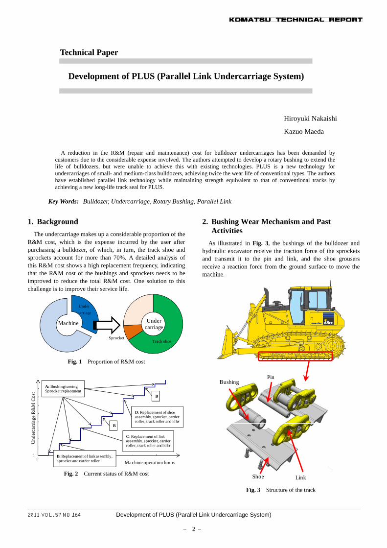
As illustrated in Fig. 3, the bushings of the bulldozer and hydraulic excavator receive the traction force of the sprockets and transmit it to the pin and link, and the shoe grousers receive a reaction force from the ground surface to move the machine.
LinkShoe
PinBushing
Fig. 3 Structure of the track
2011 VOL. 57 NO.164 Development of PLUS (Parallel Link Undercarriage System)
― 3 ―
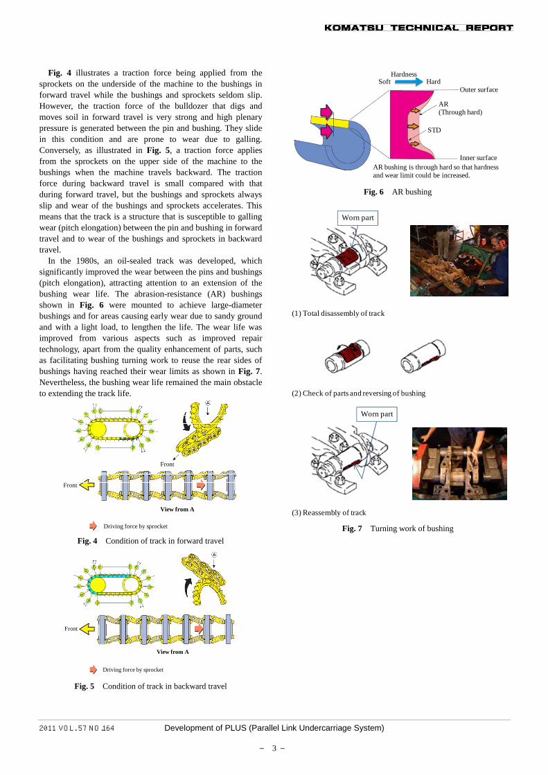
Fig. 4 illustrates a traction force being applied from the sprockets on the underside of the machine to the bushings in forward travel while the bushings and sprockets seldom slip. However, the traction force of the bulldozer that digs and moves soil in forward travel is very strong and high plenary pressure is generated between the pin and bushing. They slide in this condition and are prone to wear due to galling. Conversely, as illustrated in Fig. 5, a traction force applies from the sprockets on the upper side of the machine to the bushings when the machine travels backward. The traction force during backward travel is small compared with that during forward travel, but the bushings and sprockets always slip and wear of the bushings and sprockets accelerates. This means that the track is a structure that is susceptible to galling wear (pitch elongation) between the pin and bushing in forward travel and to wear of the bushings and sprockets in backward travel.
In the 1980s, an oil-sealed track was developed, which significantly improved the wear between the pins and bushings (pitch elongation), attracting attention to an extension of the bushing wear life. The abrasion-resistance (AR) bushings shown in Fig. 6 were mounted to achieve large-diameter bushings and for areas causing early wear due to sandy ground and with a light load, to lengthen the life. The wear life was improved from various aspects such as improved repair technology, apart from the quality enhancement of parts, such as facilitating bushing turning work to reuse the rear sides of bushings having reached their wear limits as shown in Fig. 7. Nevertheless, the bushing wear life remained the main obstacle to extending the track life.
Front
Front
View from A
Driving force by sprocket Fig. 4 Condition of track in forward travel
Front
View from A
Driving force by sprocket Fig. 5 Condition of track in backward travel
HardnessSoft Hard
Outer surface
AR(Through hard)
STD
Inner surfaceAR bushing is through hard so that hardness and wear limit could be increased.
Fig. 6 AR bushing
Worn part
(1) Total disassembly of track
(2) Check of parts and reversing of bushing
Worn part
(3) Reassembly of track Fig. 7 Turning work of bushing
2011 VOL. 57 NO.164 Development of PLUS (Parallel Link Undercarriage System)
― 4 ―
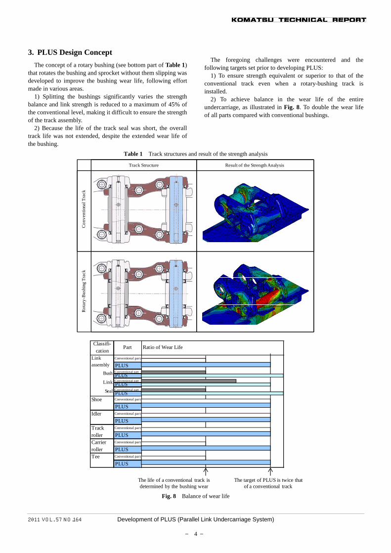
3. PLUS Design Concept The concept of a rotary bushing (see bottom part of Table 1)
that rotates the bushing and sprocket without them slipping was developed to improve the bushing wear life, following effort made in various areas.
1) Splitting the bushings significantly varies the strength balance and link strength is reduced to a maximum of 45% of the conventional level, making it difficult to ensure the strength of the track assembly.
2) Because the life of the track seal was short, the overall track life was not extended, despite the extended wear life of the bushing.
The foregoing challenges were encountered and the
following targets set prior to developing PLUS: 1) To ensure strength equivalent or superior to that of the
conventional track even when a rotary-bushing track is installed.
2) To achieve balance in the wear life of the entire undercarriage, as illustrated in Fig. 8. To double the wear life of all parts compared with conventional bushings.
Table 1 Track structures and result of the strength analysis
Track Structure Result of the Strength Analysis
Con
vent
iona
l Tra
ckR
otar
y-B
ushi
ng T
rack
The life of a conventional track is determined by the bushing wear
The target of PLUS is twice that of a conventional track
Conventional part
PLUSConventional partPLUSConventional partPLUSConventional partPLUS
Shoe Conventional part
PLUSIdler Conventional part
PLUSConventional part
PLUSConventional part
PLUSTee Conventional part
PLUS
Part Ratio of Wear Life
TrackrollerCarrierroller
Linkassembly
Bush
Link
Seal
Classifi-cation
Fig. 8 Balance of wear life
2011 VOL. 57 NO.164 Development of PLUS (Parallel Link Undercarriage System)
― 5 ―
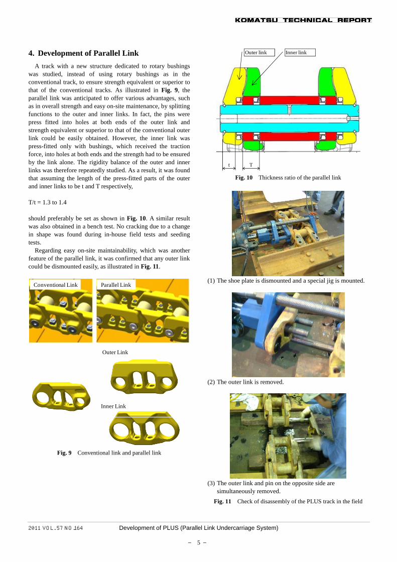
4. Development of Parallel Link A track with a new structure dedicated to rotary bushings
was studied, instead of using rotary bushings as in the conventional track, to ensure strength equivalent or superior to that of the conventional tracks. As illustrated in Fig. 9, the parallel link was anticipated to offer various advantages, such as in overall strength and easy on-site maintenance, by splitting functions to the outer and inner links. In fact, the pins were press fitted into holes at both ends of the outer link and strength equivalent or superior to that of the conventional outer link could be easily obtained. However, the inner link was press-fitted only with bushings, which received the traction force, into holes at both ends and the strength had to be ensured by the link alone. The rigidity balance of the outer and inner links was therefore repeatedly studied. As a result, it was found that assuming the length of the press-fitted parts of the outer and inner links to be t and T respectively, T/t = 1.3 to 1.4 should preferably be set as shown in Fig. 10. A similar result was also obtained in a bench test. No cracking due to a change in shape was found during in-house field tests and seeding tests.
Regarding easy on-site maintainability, which was another feature of the parallel link, it was confirmed that any outer link could be dismounted easily, as illustrated in Fig. 11.
Conventional Link Parallel Link
Inner Link
Outer Link
Fig. 9 Conventional link and parallel link
t T
Outer link Inner link
Fig. 10 Thickness ratio of the parallel link
(1) The shoe plate is dismounted and a special jig is mounted.
(2) The outer link is removed.
(3) The outer link and pin on the opposite side are
simultaneously removed. Fig. 11 Check of disassembly of the PLUS track in the field
2011 VOL. 57 NO.164 Development of PLUS (Parallel Link Undercarriage System)
― 6 ―
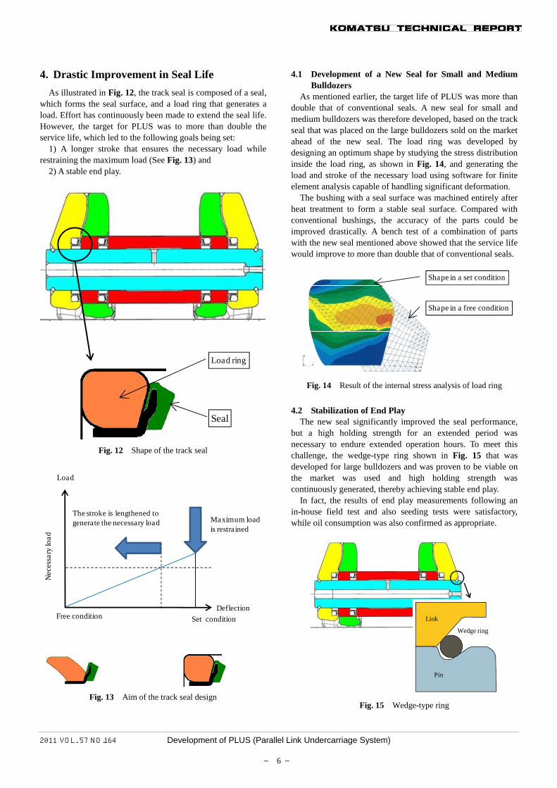
4. Drastic Improvement in Seal Life As illustrated in Fig. 12, the track seal is composed of a seal,
which forms the seal surface, and a load ring that generates a load. Effort has continuously been made to extend the seal life. However, the target for PLUS was to more than double the service life, which led to the following goals being set:
1) A longer stroke that ensures the necessary load while restraining the maximum load (See Fig. 13) and
2) A stable end play.
Load ring
Seal
Fig. 12 Shape of the track seal
Deflection
Load
Set condition
Maximum load is restra ined
The stroke is lengthened to generate the necessary load
Free condition
Nec
essa
ry lo
ad
Fig. 13 Aim of the track seal design
4.1 Development of a New Seal for Small and Medium Bulldozers
As mentioned earlier, the target life of PLUS was more than double that of conventional seals. A new seal for small and medium bulldozers was therefore developed, based on the track seal that was placed on the large bulldozers sold on the market ahead of the new seal. The load ring was developed by designing an optimum shape by studying the stress distribution inside the load ring, as shown in Fig. 14, and generating the load and stroke of the necessary load using software for finite element analysis capable of handling significant deformation.
The bushing with a seal surface was machined entirely after heat treatment to form a stable seal surface. Compared with conventional bushings, the accuracy of the parts could be improved drastically. A bench test of a combination of parts with the new seal mentioned above showed that the service life would improve to more than double that of conventional seals.
Shape in a set condition
Shape in a free condition
Fig. 14 Result of the internal stress analysis of load ring
4.2 Stabilization of End Play
The new seal significantly improved the seal performance, but a high holding strength for an extended period was necessary to endure extended operation hours. To meet this challenge, the wedge-type ring shown in Fig. 15 that was developed for large bulldozers and was proven to be viable on the market was used and high holding strength was continuously generated, thereby achieving stable end play.
In fact, the results of end play measurements following an in-house field test and also seeding tests were satisfactory, while oil consumption was also confirmed as appropriate.
Link
Pin
Wedge ring
Fig. 15 Wedge-type ring
2011 VOL. 57 NO.164 Development of PLUS (Parallel Link Undercarriage System)
― 7 ―
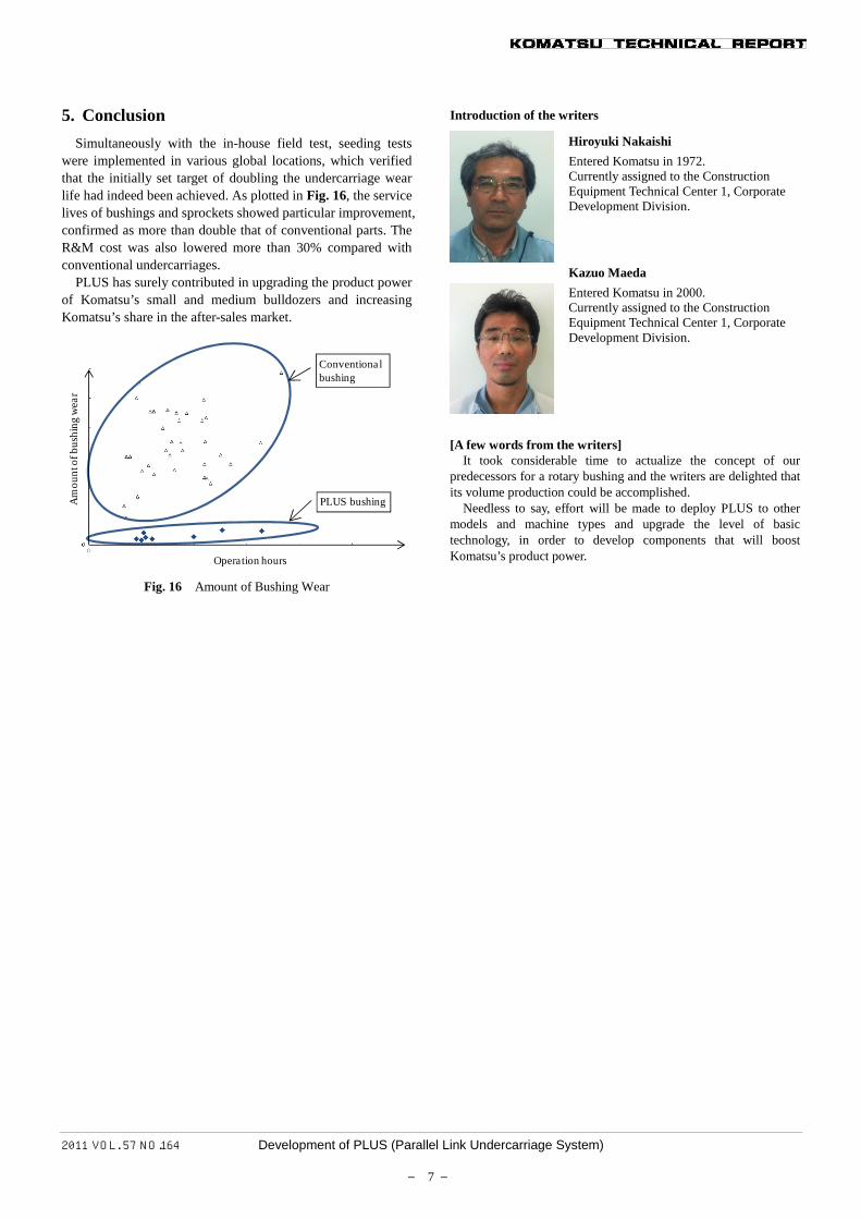
5. Conclusion Simultaneously with the in-house field test, seeding tests
were implemented in various global locations, which verified that the initially set target of doubling the undercarriage wear life had indeed been achieved. As plotted in Fig. 16, the service lives of bushings and sprockets showed particular improvement, confirmed as more than double that of conventional parts. The R&M cost was also lowered more than 30% compared with conventional undercarriages.
PLUS has surely contributed in upgrading the product power of Komatsu’s small and medium bulldozers and increasing Komatsu’s share in the after-sales market.
Operation hours
Am
ount
of b
ushi
ng w
ear
Conventional bushing
PLUS bushing
Fig. 16 Amount of Bushing Wear
Introduction of the writers
Hiroyuki Nakaishi Entered Komatsu in 1972. Currently assigned to the Construction Equipment Technical Center 1, Corporate Development Division.
Kazuo Maeda Entered Komatsu in 2000. Currently assigned to the Construction Equipment Technical Center 1, Corporate Development Division.
[A few words from the writers]
It took considerable time to actualize the concept of our predecessors for a rotary bushing and the writers are delighted that its volume production could be accomplished.
Needless to say, effort will be made to deploy PLUS to other models and machine types and upgrade the level of basic technology, in order to develop components that will boost Komatsu’s product power.