Embed Size (px)
Citation preview

Copyright © 2013 JFE Steel Corporation. All Rights Reserved. 1
Development of PSA Systemfor the Recovery of CO2from Blast Furnace Gas
H.Saima, Y.Mogi, T.HaraokaJFE Steel Corp.
IEA-GHG IETS Iron and Steel Industry Workshop, Tokyo, Japan
Nov. 05 2013
E-mail : [email protected]

Copyright © 2013 JFE Steel Corporation. All Rights Reserved. 2
Blast Furnace
Blast Furnace
Iron ore
Coke
Hot Air
Fe2O3 + CO → 2Fe + 3CO2
2C + O2 → 2CO
~2,000℃
150~200℃
(Fe2O3)
(C)
Molten Iron(Fe)
Blast Furnace GasCO : 23% CO2 : 22%N2 : 52% H2 : 3%Ambient Pressure ~130kPa
Important Fuel GasMain Origin of CO2
(1,000~1,100℃)

Copyright © 2013 JFE Steel Corporation. All Rights Reserved. 3
CO2 Emission in Japan
CO2 emission from Steel Works is around 15%Reduction of CO2 is an important subject for Steel Makers
JISF* starts COURSE 50** Project
*JISF : Japan Iron and Steel Federation
186
Japan1,256 Mt(2010)
Steel Works(15%)
COURSE 50 : CO2 Ultimate Reduction of Steel-making Process by InnovativeTechnology for Cool Earth 50
(STEP 1 2008-2012)
CO2 emission in Japan lies around 1.0-1.3 billion tons per year
(STEP 2 2013-2017)

Copyright © 2013 JFE Steel Corporation. All Rights Reserved. 4
Subjects in COURSE 50
Coke Oven
COG
H2
(H2:50-60%)
Amine
PSA
Separation
CCS?CO2
BFG (CO2:21-23%)
Blast Furnace
Heat RecoverySteam, Power Supply
Our subject
Use of H2 at Blast Furnace for Iron Ore ReductionSeparation of CO2 from BFG with amine or PSARecovery of Wasted Heat to supply separation energy

Copyright © 2013 JFE Steel Corporation. All Rights Reserved. 5
BlastFurnace
CO2
N2
CO
H2
CO,N2
Inflamable Gas
Fuel Gas
Gas SeparationUnit (PSA)
Adsorbent
for CO2
Adsorbentfor CO
CO2
CO
N2
H2
22%23%
52%
3%
Outline of PSA Project
•CO2 Recovery ≧80% or CO2 Purity ≧90%•Flamable Gas Recovery ≧90%•Reduction of CO2 Recovery Cost >50% (≦2,000yen/t)
Target

Copyright © 2013 JFE Steel Corporation. All Rights Reserved. 6
Laboratory PSA Apparatus
PSA Tower : ID.40mm x 500mmHx 4 Towers system
Feed Gas : CO2, CO, N2, H2
Each flow rate is controlled independently and mixed.
(Usually use 3towers]

Copyright © 2013 JFE Steel Corporation. All Rights Reserved. 7
DesorptionRinse
Adsorption Rinse
BFG
N2,CO
CO2
CO2
Vacuum Pump
Press. & Adsorption
Cycle Time
Desorption
3 Steps 3 Towers PSA System

Copyright © 2013 JFE Steel Corporation. All Rights Reserved. 8
Zeolum F-9H
Active Carbon
CO2 Purity (%)
CO2
Reco
very
(%)
Evaluation by Laboratory PSA
Zeolum F-9H shows high performance in PSA system.Technical target of the project is achieved. (blue area)
Adsorption200kPa*
Desorption7kPa*
*absolutepressure
Cycle Time630sec
Copyright © 2013 JFE Steel Corporation. All Rights Reserved. 9
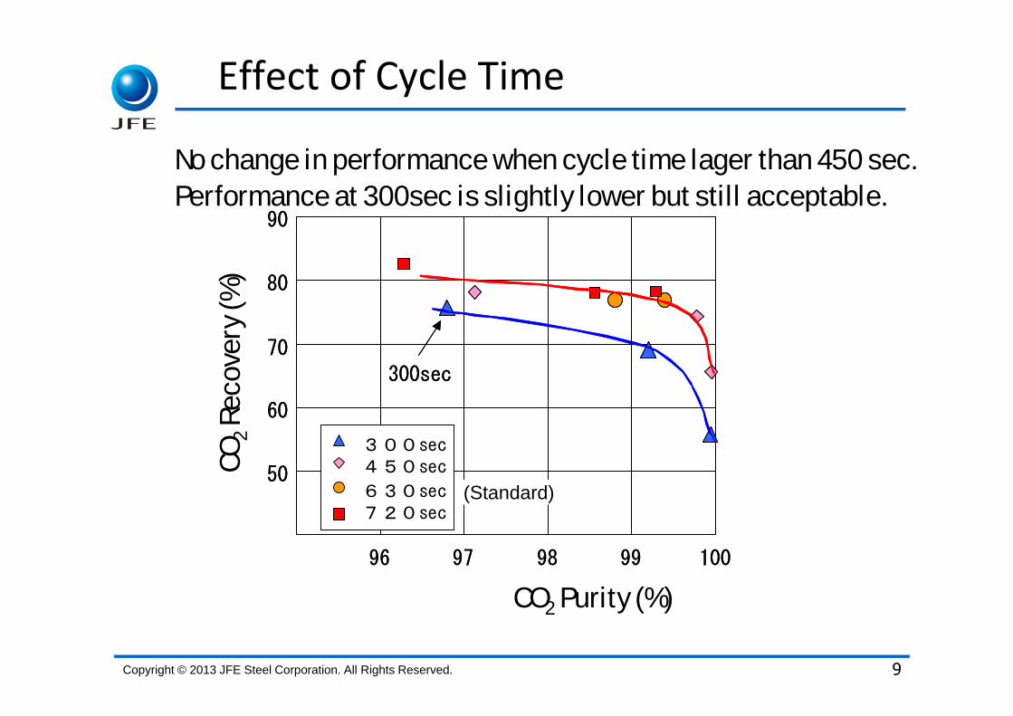
Effect of Cycle Time
50
60
70
80
90
96 97 98 99 100
300sec450sec
630sec720sec
300sec
50
60
70
80
90
96 97 98 99 100
300sec450sec
630sec720sec
300sec
CO2 Purity (%)
CO2
Reco
very
(%)
No change in performance when cycle time lager than 450 sec.Performance at 300sec is slightly lower but still acceptable.
(Standard)

Copyright © 2013 JFE Steel Corporation. All Rights Reserved. 10
Effects of CO2 Concentration in Feed Gas
0
2
4
6
8
10
12
14
16
18
20
22% 27% 32% 37%
CO2 Conc. In Raw Gas(%)
CO
2 F
low
Rate
(NL/m
in/kg
)
0.0
0.2
0.4
0.6
0.8
1.0
1.2
1.4
1.6
1.8
2.0
Ratio o
f C
O2
Flo
w R
ate
(-)
Feed
Recovery
Recovery
Feed
Higher CO2 concentration leads higher recovery rate.
Gas Feed Rate: Constant
CO2 Conc. In Raw Gas(%)

Copyright © 2013 JFE Steel Corporation. All Rights Reserved. 11
Recovery Cost Estimated from Laboratory Results
Total cost is reduced at shorter cycle time because of lower capital cost and higher CO2 concentration leads more advantage.
-
1,000
2,000
3,000
4,000
Recovery
Cost(
\/t)
630 300 300 Target
Cycle Time (sec)
Cap
ital
Pow
er
High CO2 Conc
Adso
rbent
High CO2 Conc
4,0402,500
2,000

Copyright © 2013 JFE Steel Corporation. All Rights Reserved. 12
ASCOA‐3* (JFE Steel Fukuyama Area)*Advanced Separation System by Carbon Oxides Adsorption
Start : March 2011
Capacity : 3tons-CO2/dayPlant Area : 21m x 25m

Copyright © 2013 JFE Steel Corporation. All Rights Reserved. 13
CO2 Adsorption Towers ID : 750mm, Height : 1,200mm

Copyright © 2013 JFE Steel Corporation. All Rights Reserved. 14
ASCOA‐3 Flow Diagram
BFG冷媒
圧縮機 ガスクーラー脱湿塔 脱硫塔
CO2-PSACO2タンク
中間タンク真 空ポンプ
中 間ブロアー
真 空ポンプ
CO-PSACOタンク
混合タンク
BFGブロアー
ブロアー
BFG冷媒
圧縮機 ガスクーラー脱湿塔 脱硫塔
CO2-PSACO2タンク
中間タンク真 空ポンプ
中 間ブロアー
真 空ポンプ
CO-PSACOタンク
混合タンク
BFGブロアー
ブロアー
Compressor Gas Cooler
Blower
Dehumidifier
Tank
VacuumPump
Tank Blower
Tank TankVacuumPump
DesulfurizingTower
300kPa-abs. 10℃ D.P -60℃

Copyright © 2013 JFE Steel Corporation. All Rights Reserved. 15
General Test Operation
0.0
0.5
1.0
1.5
2.0
2.5
3.0
3.5
4.0
4.5
5.0
3/8
3/11
3/11
3/14
3/15
3/16
3/17
3/18
3/22
3/23
3/24
CO
2 R
ecove
ry(t
/da
y)
0
10
20
30
40
50
60
70
80
90
100
CO
2 P
urity
, Recove
ry R
atio
(%)
Recover target:3t/day
Purity target:90%
Recovery ratio target 80%
Recovery Ratio
Purity
Achieve 3 targets
Max. Recovery:4.3t/day
Max. Purity:99.5%
Recovery
All technical targets were cleared during test operation period.

Copyright © 2013 JFE Steel Corporation. All Rights Reserved. 16
Cost Reduction‐Power Consumption of Vacuum Pump‐
3.5
5.2
6.3186
121 123
2
3
4
5
6
7
CO2 22%C.T. 300sec.
CO2 34%C.T. 300sec.
CO2 33%C.T.225sec.
CO
2 R
ecovr
y(t/
Day
)
100
120
140
160
180
200
V.P
um
p P
ow
er
Consu
mpt
ion(k
Whr/
t)
Higher CO2 recovery leads lower power consumption

Copyright © 2013 JFE Steel Corporation. All Rights Reserved. 17
Further Cost Reduction (Higher Dew Point)
Operation is stable even at a higher dew point.
3
4
5
6
7
8
0 200 400 600 800 1000
Process Time (hr)
CO
2 R
ecove
ry(t
/day
)
(Dew point of raw gas:-60→-30℃)
Gas Pressure : 50kPa CO2 Conc. : 33-34%
5tons/day Condition (Cycle Time : 300sec.)
6tons/day Condition (Cycle Time : 225sec.)

Copyright © 2013 JFE Steel Corporation. All Rights Reserved. 18
CO2 Adsorption Towers
CenterHalf Radius
Wall Side
11 Resistance Thermometers

Copyright © 2013 JFE Steel Corporation. All Rights Reserved. 19
0
5
10
15
20
25
30
0 50 100 150 200 250 300
Time/sec.
Tem
pera
ture
/D
egr
ee C
entigr
ade
600h Center 80h Center
600h half radius 80h Half radius
600h Wall side 80h Wall Side
Temperature Distribution(Horizontal Direction)
Gas Outlet
ResistanceThermometer
Gas Inlet
80h
340h
600h
840h
1100h
height/mm
Temperatures at center and half radius move simultaneously

Copyright © 2013 JFE Steel Corporation. All Rights Reserved. 20
Temperature Distribution
Temperature change indicates adsorption-desorption behavior of CO2
Adsorption-Desorption behaviors at center and half radius are the same.
It is easy to scale-up the adsorption tower to the horizontal direction.
☆
☆
Homogeneity of gas flow in enormous adsorption tower?☆
Copyright © 2013 JFE Steel Corporation. All Rights Reserved. 21
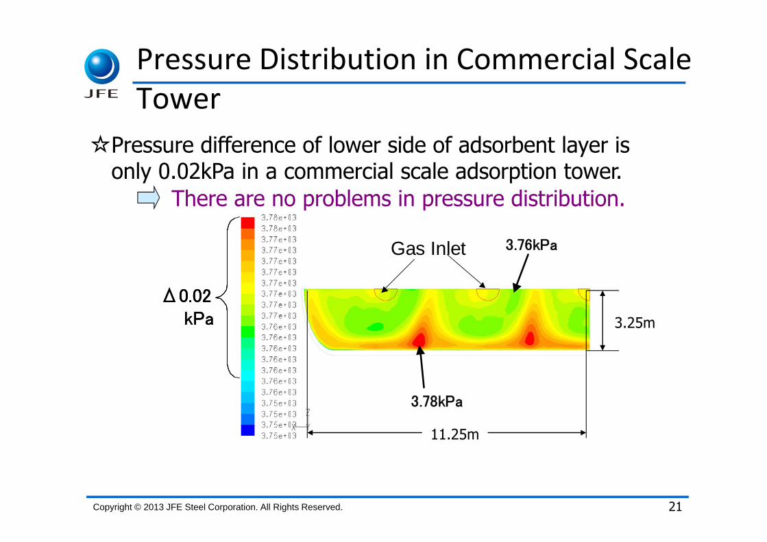
Pressure Distribution in Commercial Scale Tower
3.76kPa
3.78kPa
Δ0.02
Gas Inlet
kPa
3.76kPa
3.78kPa
Δ0.02
Gas Inlet
kPa
3.76kPa
3.78kPa
Δ0.02
Gas Inlet
kPa 3.25m
11.25m
Pressure difference of lower side of adsorbent layer is only 0.02kPa in a commercial scale adsorption tower.
There are no problems in pressure distribution.
☆

Copyright © 2013 JFE Steel Corporation. All Rights Reserved.
Design of Adsorption Tower
22
17000
1500ID 4000
Adsorbent Layer
Adsorbent : Zeolum F-9HSize : 4,000mmΦ×17,000mm
Adsorption Tower
Weight : 50tonsMaterial : SM490B
Thickness : 12mm
Designed Pressure : 190kPa/FV
Apparent Density : 0.65kg/LWeight : 65tons

Copyright © 2013 JFE Steel Corporation. All Rights Reserved. 23
Commercial Plant Image (Capacity : 1Mt‐CO2/y)
150m
95m
BeforeDevelopment
After Development1Mt/y
Investment:15B¥200kt/y×5units
Compressor
95m-α
60m
1.26Mt/y
500kt/y×2units
Blower (Common)
Vacuum Pump
Investment:7B¥
6.5mφ×23m
Tower
4mφ×17mTower
Vacuum Pump

Copyright © 2013 JFE Steel Corporation. All Rights Reserved.
Recovery Cost Estimation
24
Recovery cost was achieved the target! (≦2,000yen/t)
Item
Capital 7,000 Million \
Unit Cost 840 \/t-CO2
Power 145 kWh/t-CO2
Steam 0.05 t/t-CO2
Utility Cost 1,060 \/t-CO2
Adsorbent 390 tons
Unit Cost 40 \/t-CO2
Total Unit Cost 1,940 \/t-CO2
Cost

Copyright © 2013 JFE Steel Corporation. All Rights Reserved.
0
1,000
2,000
3,000
4,000
5,000
Recovery
Cost(
Yen/t-
CO
2)
Initial ASCOA-3 Target
Utility
Capital
Adsorbent
4,040
2,0001,940
25
Cost Estimation from ASCOA‐3 Operation Results
($41/t)
($20/t) ($21/t)

Copyright © 2013 JFE Steel Corporation. All Rights Reserved. 26
Summery
1. Zeolite type adsorbent has a good performance in Laboratory PSA and ASCOA-3
2. Shorter cycle time and higher CO2 concentration in BFG reduce the cost for CO2 separation
3. The size of commercial adsorption tower was reduced to 1/3~1/4 as the fruit of development
4. CO2 recovery cost achieved the target through the operation result with ASCOA-3 and imaging the design of commercial plant
E-mail : [email protected]
AcknowledgementWe appreciate to NEDO for their financial support.

Copyright © 2013 JFE Steel Corporation. All Rights Reserved. 27
Thank you for your attention!

Copyright © 2013 JFE Steel Corporation. All Rights Reserved.
Any reproduction, modification, translation, distribution, transmission, uploading of the contents of the document, in whole or in part, is strictly prohibited
28