Embed Size (px)
Citation preview
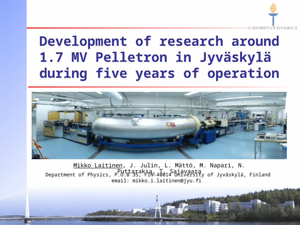
Development of research around 1.7 MV Pelletron in Jyväskylä
during five years of operation
Mikko Laitinen, J. Julin, L. Mättö, M. Napari, N. Puttaraksa, T. Sajavaara
Department of Physics, P.O.B 35, FIN-40014 University of Jyväskylä, Finlandemail: [email protected]

Outlook Background: Who we are
Moving the 1.7MV Pelletron to Jyväskylä
Water leak at the SF6 heat exchanger From corona needles to resistors
Turbopumped stripper system installation
Beamlines and recent developments
‘Contaminants’ after analyzing magnet

University: Staff 2600, 15000 Students, 217 M€ turnover Department: Personnel 190, including 85 PhD students
Physics department main research areas:• Nuclear and accelerator based physics
• One team out of 8 : Accelerator based materials physics• Materials physics• High- energy physics
NordForsk 2011: Comparing Research at Nordic Universities using Bibliometric Indicators Among 30 Nordic Universities,
JyU is among the top four universities in Physics + Mathematics
(“second place” after Aarhus U.)
University of Jyväskylä,Department of Physics (JYFL)

Accelerator based materials physics 1 Senior, no other staff, including engineers
4-5 PhD students (for example: ion beam lithography, detector development, direct signal digitization by fast digitizers)
4-6 Master (and bachelor) thesis students24/7 working diffusion cloud chamber for physics department
permanent exhibiton: Masters thesis project
Commercial systemprice tag: 25-50k€depending on size
MOVING THE 1.7MV PELLETRON TO JYVÄSKYLÄ

Acquisition of the Pelletron accelerator
A coffee table rumor was heard in late 2006…… and quickly confirmed by indirect route
The technical research center of Finland (VTT) had little usage of their accelerator and needed the room space for cleanroom extension.. …And our group in Jyväskylä needed an accelerator.
1.7MV 5SDH-2 Pelletron(serial number 002, made in 1985)
with one (Alphatross) ion source and one beam line was donated to JYU by VTT

Monday 18th of September 2006
Moving the accelerator from VTT

Monday 18th of September 2006
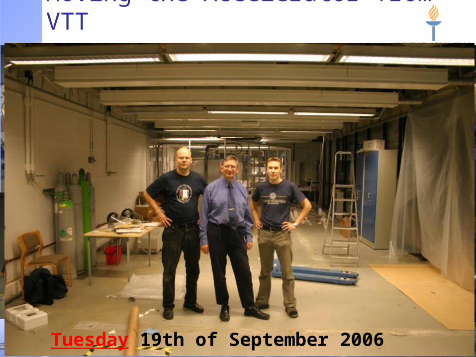
Moving the Accelerator from VTT
SF6 purity 88%!
No moisture 19ppmV
Purity analysis bySolvay Germany
Herkunft Gebinde GewichtAnteil SF6
SF6 Luft CF4 CO2 SO2F2 SO2 S2F10 SF5-O-SF5
Art Nr. kg Vol-% Vol-% Vol-% Vol-% ppmv ppmv ppmv ppmv
Wikeström, Helsinki Flasche 72356 28 18 65.2939 34.706 0.0206
Wikeström, Helsinki Flasche 74390 21 16 75.2364 24.231 0.0699 0.0226 0.28837 0.01014
Wikeström, Helsinki Flasche 12780 30 28 93.8826 6.1131 0.001 0.00009 0.00516
Wikeström, Helsinki Flasche 9977952 33 30 89.6052 10.395 0.0022 0.00027 0.00558
S2F10 was considered a potential chemical warfare agent in World War II because it does not produce lacrimation or skin irritation, thus providing little warning of exposure. LD50 levels about 15-25 ppm
1ATM of air+ 5bar SF6 overpressure!
Moving the Accelerator from VTT
Tuesday 19th of September 2006

Arriving at Jyväskylä after 330km
25th of September 2006

5th of October 200626th of October 200630th of November 2006
Building of the Pelletron lab
Pelletron
Target hall

14th of December 2006
Installing of the Pelletron

Installing of the Pelletron
17th of December 20062nd of January 2007January 2007

Cleaning of the Pelletron
17th of January 2007
18th of January 2007

Powering up of the Pelletron acc.
6th of February 2006

Ion source cleaning + comissioning

First RBS measurements
0
200
400
600
800
1000
1200
150 250 350 450 550
Energy (ch)
Yie
ld
Experimental
SIMNRA simulation
0
100
200
300
400
500
600
700
120 220 320 420 520
Energy (ch)
Yie
ld
Experimental
SIMNRA simulation
Thin (170 nm) hydroxyapatite Thick (550 nm) hydroxyapatite
Ca
P
O
Si-substrate
Ca/P ratio 1.18 Ca/P ratio 1.33
Beam on target: 21.2.2007Total commissioning time from ‘amateurs’: ~2months

WATER LEAK AT THE SF6 HEAT EXCHANGER

Water leakage from the heat EX
Beginning of September 2007Beginning of September 2007
First symptom: Voltage(GVM) didn’t go DOWN when chains were turned off
Real signal: Voltage rised very poorly, even after long “conditioning” (about 1.5 weeks from first symptoms)

Water leakage from the heat EX
55thth of October 2007 of October 2007
Measuring the purity of SF6: 99.6% (27.9.2007) Water content in SF6: 7500 ppmV !!! (19 @ VTT)

Water leakage from the heat EX
55thth of October 2007, of October 2007, almost a month from first symptomsalmost a month from first symptoms

Water leakage from the heat EX
9/26/2007 10/3/2007 10/10/2007 10/17/2007 10/24/2007 10/31/2007
0
1000
2000
3000
4000
5000
6000
7000
8000
9000
0
1000
2000
3000
4000
5000
6000
7000
8000
9000
Problemverified
H2O
co
nte
nt
aft
er
dry
er
[pp
mV]
H2O
co
nte
nt
of
SF 6 in
ta
nk
[p
pm V
]
Time [days]
Dry alumina changes
Water condensation@ ~7500ppm
V H
2O
in [email protected] bar, 24C
Pressure changedin Vaisala dewpoint
meter to 2.2 bar
Pumping few days of the external heat exhanger tubing with dry scroll pump.
A lot of water out from alumina
New alumina in -> gas circulation

Water leakage from the heat EX Conclusions and aftermath of the water
leakage after tank opening + cleaning: There had been few cm of liquid water
inside the tank bottom (“high water” -mark)
New “pure” ion exchanged water at new lab might enhanced corrosion of the rusted Cu pipes of the original heat exhanger
Only aftermath was most likely the GVM bearings that failed less than month later: forced tank opening and gas recovery

FROM CORONA NEEDLES TO RESISTORSANDTURBOPUMPED STRIPPER SYSTEM INSTALLATION

From corona needles to resistors 550 Mohm resistors ordered from NEC to replace some 60 corona gaps
Resistor based charge division change was relatively easy, except tight space
Lower voltages far more stable, accelerator has been run with 75kV at terminal
From corona needle based voltage division to resistorsFrom corona needle based voltage division to resistors
20082008
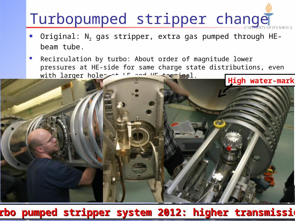
Turbopumped stripper change Original: N2 gas stripper, extra gas pumped through HE- beam tube.
Recirculation by turbo: About order of magnitude lower pressures at HE-side for same charge state distributions, even with larger holes at LE and HE terminal.
Less beam (charge state-)contamination due to residual stripper gas.
Turbo pumped stripper system 2012: higher transmissionTurbo pumped stripper system 2012: higher transmission
High water-mark

BEAM LINES AND RECENT DEVELOPMENTS

The lab and the beam lines 2009

Low energy heavy ion ERDA Typically 1–20 MeV Cl, Br, I or Au ions from 1–3 MV tandem accelerator
Time-of-flight–energy spectrometers for isotopic identificationand energy spectrum measurement
Time of flight (velocity) and energyare measured for the same particle
E=½mv2 → m=2E/v2
Different masses can be identified
63Cu

Example: Thin film with high mass element Atomic layer deposited Ru film on HF cleaned Si
Scattered beam, 35Cl, used for Ru deph profile
Monte Carlo simulations needed for getting reliable values for light impurities at the middle of the film
Ru
Si
SiO2
Low energy heavy ion ERDA – See posters!
Poor E resolution

Gas ionization detector to replace Si-energy detector Why try to fix a well working system?
Greatly improved energy resolution for low energy heavy ions → heavier masses can be resolved
Gas detector is 1D position sensitive by nature → possibility for kinematic correction and therefore larger solid angles possible
Gas detector does not suffer from ion bombardment
10.2 MeV 79Br 8.5 MeV 35Cl
Recoil ranges in isobutane
Gas ionization detector develoment – See posters!
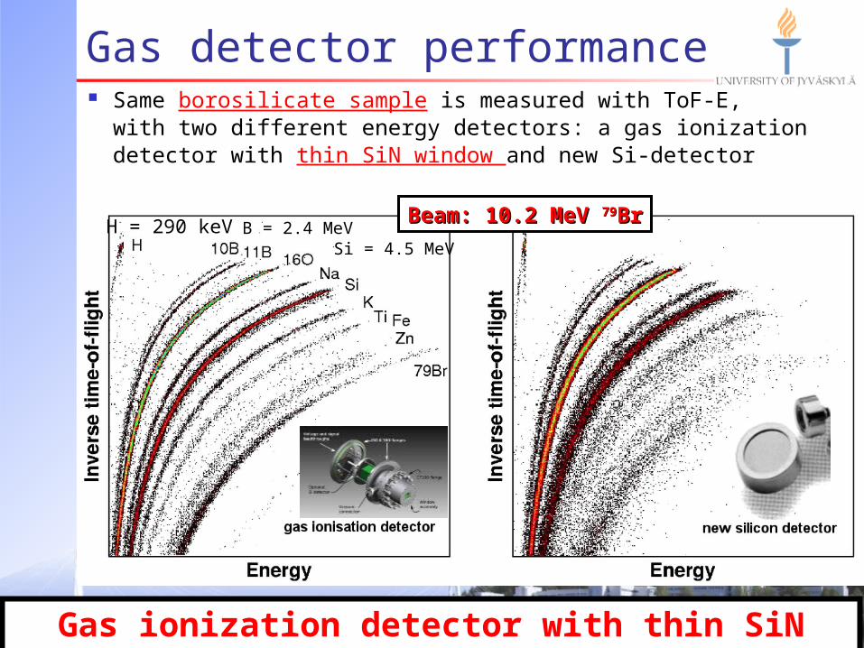
Gas detector performance Same borosilicate sample is measured with ToF-E,
with two different energy detectors: a gas ionization detector with thin SiN window and new Si-detector
Gas ionization detector with thin SiN window
Beam: 10.2 MeV Beam: 10.2 MeV 7979BrBrB = 2.4 MeVH = 290 keV
Si = 4.5 MeV

‘Contaminants’ after analyzing magnet 13.6 MeV 63Cu7+ CaPO (hydroxyapatite)
Si
H
C
P Ca
Cu beam
O
Multiple (charge) statesof same ion but withdifferent energiesbend at the analysingmagnet through sameslit to same angle
Is this mostly due to stripper gas effect in HE column?
Stripper N

Acknowledgements
Accelerator based materials physics
group at JYFL
TEKES-EU Regional Funds
Academy of Finland
TEKES


Pelletron Laboratory 25 years old 1.7 MV Pelletron accelerator, in Jyväskylä since 2006
Available beams and energies: from H to Au, from 0.2 MeV to 20+ MeV
Three ion sourceswithin ~2 m2 !
100 cm100 cm

Ion sources Mean life time of the ion source more important than 2×more beam
Maintained by group, development together with ion source team
Alphatross 100 MHz RF, Rb charge exhange He- 250 nA
SNICS '1' Cs sputtering, single cathode C-, Cl-, Cu-, Br- 2 000 nA
PELLIS Filament driven multicusp H- 15 000 nA
Ion source name
Ion source typeprimary
ion(s)Typical
intensities
"cathode" HV, currentfilament P,
oven TEinzel
focusing HV'Extraction'
lens HV
Alphatross +5 kV, 0.75 mA 250 oC / 55 oC none -8 kV
SNICS '1' -4 kV, < 0.2 mA 19 A, 6 V -8 kV -8 kV
PELLIS +100 V, 1 A 70 A, 3 V -5.5 and -3.4 kV -10 kV
Typical operational parametersIon source name

Where does the ions end up
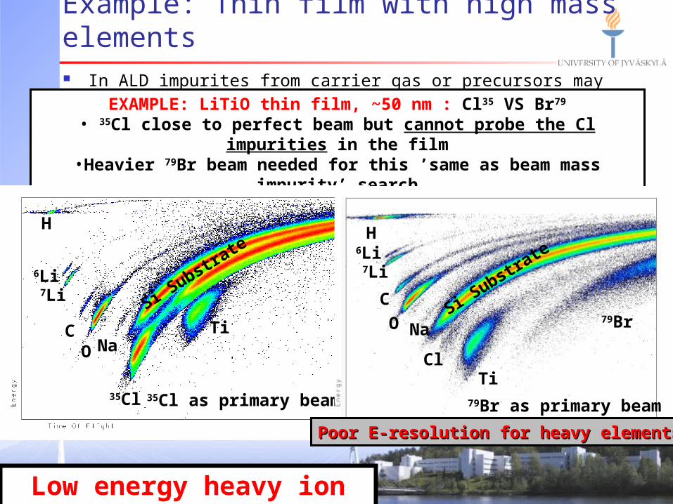
Example: Thin film with high mass elements In ALD impurites from carrier gas or precursors may interfere in the process
EXAMPLE: LiTiO thin film, ~50 nm : Cl35 VS Br79
• 35Cl close to perfect beam but cannot probe the Cl impurities in the film•Heavier 79Br beam needed for this ’same as beam mass impurity’ search•Br beam suffers from multiple scattering and cannot probe whole film
Low energy heavy ion ERDA
Ti
Si Substra
te
NaOC
6Li
35Cl
7Li
H
35Cl as primary beam
No Chlorine impurities seenNo Chlorine impurities seen
ClTi
Si Substra
teH
NaO
C
6Li7Li
79Br
79Br as primary beam
Poor E-resolution for heavy elementsPoor E-resolution for heavy elements

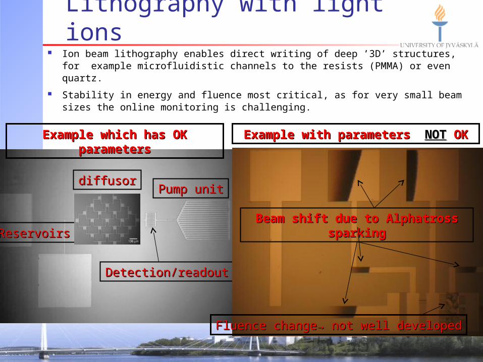
Lithography with light ions Ion beam lithography enables direct writing of deep ’3D’ structures,
for example microfluidistic channels to the resists (PMMA) or even quartz.
Stability in energy and fluence most critical, as for very small beam sizes the online monitoring is challencing.
Uniform beam(up to ~30%), parallel exposure trough slits → fast prototyping.
Depth defined by ion rangeDepth defined by ion range
Lithography with light ions Ion beam lithography enables direct writing of deep ’3D’ structures,
for example microfluidistic channels to the resists (PMMA) or even quartz.
Stability in energy and fluence most critical, as for very small beam sizes the online monitoring is challenging.
Pump unitPump unit
ReservoirsReservoirs
diffusordiffusor
Detection/readoutDetection/readout
Beam shift due to Alphatross sparkingBeam shift due to Alphatross sparking
Fluence change→ not well developedFluence change→ not well developed
Example which has OK parametersExample which has OK parameters Example with parameters Example with parameters NOTNOT OK OK

1472 1488 1504 1520 1536 1552 1568 1584 1600
0
250
500
750
1000
1250
1500
50 keV Pb implantation doses in glass
1E16 at. cm-2
3E15 at. cm-2
1E15 at. cm-2
3E14 at. cm-2
Inte
nsi
ty [
cou
nts
]
Backscattered energy [keV]
As-implanted = highest peak for every dose
460 oC 1 h
480 oC 1 h
500 oC 1 h
520 oC 1 h
540 oC 1 h
560 oC 1 h = lowest peak for every dose
Need for negative helium Rutherford Backscattering Spectrometry (RBS) uses often He to probe the
sample from the surface (few 10’s of nm to few µm).
Higher the energy, lower the backscattering yield, but better mass resolution (and relative energy resolution at silicon detector).
Lower the energy, better the depth resolution, but worse transmission through the accelerator → High He input current needed from ion source.
1472 1488 1504 1520 1536 1552 1568 1584 1600
0
25
50
75
100
125
150
175
200
Backscattered energy [keV]
Inte
nsi
ty [
cou
nts
]
50 keV Pb implantation doses in glass
1E16 at. cm-2
3E15 at. cm-2
1E15 at. cm-2
3E14 at. cm-2
EXAMPLE: RBS for Pb that has diffused in glass at elevated temperatures
2 more doses! 2 more doses! - 1E14 at. cm- 1E14 at. cm-2-2
- 3E13 at. cm- 3E13 at. cm-2-2

What is needed: Conclusions I ToF-ERDA: Selection of heavy ions that are fast to switch,
stability in intensity not that important but higher charge states from small accelerator is needed for reasonable count rates.
Lithography: Stability in both energy and intensity most important. Light ions can create deep ’open’ structures where heavy ions can create closed channels directly (Bragg peak).
RBS: Helium beam most used beam as it can separate heavy target/sample masses from each other
PIXE (particle induced x-ray emission): Protons or helium most often used. Data can be collected often together with other methods easily.

What is needed: Conclusions II For ion beam applications, for both characterization and
modification variety of negative ion beams is needed.
Stable in energy and fluence, easy to maintain ion sources are priority parameters over higher beam intensities.
Protons:Protons: PELLIS H- source performs very well with long life times and is easy to operate by users.
Helium: Helium: Alphatross currently has poor to worse performance. Upgrades coming: helical RF-plasma coupling and temperature stabilized Rb charge exchange chamber for stable Rb backflow to oven.
Heavy ions:Heavy ions: SNICS ’1’ has moderate performance. ”New” 40 MC-SNICS to be installed still in this year.

Growth of Al2O3 on TiO2
In dye sensitized solar cells even single ALD cycles of Al2O3 were
found to reduce the interfacial electron transfer between semiconductor TiO2 and dye
molecule. This improves the performance of the cell.
How thick films of Al2O3 were
deposited during first cycles of ALD growth?
50 nm ALD-TiO2
Liisa Antila, Mikko Heikkilä, Viivi Aumanen, Marianna Kemell, Pasi Myllyperkiö, Markku Leskelä, and Jouko E. I. Korppi-TommolaJ. Phys. Chem. Lett. 1, 536 (2010).

Minimizing background
Si substrate
50 nm TiO2
Sample:50 nm TiO2 on Si substrate where 5 ALD cycles of Al2O3 has been grow on to (corresponding 0.5 nm thickness)
All counts visible on log intensity scale
5 ALD cycles of Al2O3

Growth of Al2O3 on TiO2
Samples with 1, 2, 3 and 5 cycles of ALD Al2O3 on 50 nm ALD TiO2 were
studied
Measurements using 8.26 MeV 79Br beam
Conclusion: Al2O3 film growth starts rapidlyfrom the first cycles and then the growth rate per cycle reduces
5 ALD cycles

Timing gates: construction Carbon foils
T1 foil 3 µg/cm2 (diameter 9 mm)
T2 foil 10 µg/cm2 (diameter 18 mm) Determines solid angle of 0.29 msr
Distance between foils 633 mm
Wires in the electrostatic mirror grids Spot-welded 25 µm diameter Au wire
Wire-to-wire distance 1 mm, 97.5% transmission, telescope transmission 87%
Micro-channel plates Low-cost chevron-type MCP assembly from TECTRA
Active diameter >40 mm, pore size 12 µm, channel length/diameter 40:1
Specified only for 10 ns timing resolution!

TOF detection efficiency
Sample holder backwall
Detection efficiency against energy detector All sample elements, including H, can be detected and quantified No pinholes in C foils
hydrogen carbon
typicalERDAenergies
(%)

Timing resolution for He and H Current timing resolution 155 ps (FWHM) for 4.8 MeV incident He ions and
235 ps for 0.6 MeV incident H ions scattered from 1-2 nm Au film on SiO2/Si substrate
155 ps235 ps
For He 155 ps timing resolution gives 32 keV resolutionat 4.8 MeV but 0.8 keV resolution at 400 keV!
4.8 MeV He 0.6 MeV H
Au Si9 keV

Example: Diamond-like carbon films 2.3 µm thick diamond-like-carbon film on Si, measured with 9 MeV 35Cl
All isotopes can be determined for light masses
Light elements can be well quantified (N content 0.05±0.02 at.%)
Low energy heavy ion ERDA

Selection of coincident events
ADC n:o Ch Timestamp0 2675 4576693833991 2624 4576693834710 3756 4576694599091 1332 4576694599820 6688 4576694992370 3044 4576698623941 1987 457669862467
Time-stamp resolution 25 ns.
Lonely TOF-event, has probably hit T2 detectorC-foil frame
TOF
energy

Selection of coincident eventsCoincidence <10µs, 585117 counts
1.6-1.9 µs, 576741 counts 1725-1750 ns, 329445 counts outside peak, <10µs

ANALYSIS OF THE Al2O3/TiO2 NANOLAMINATES
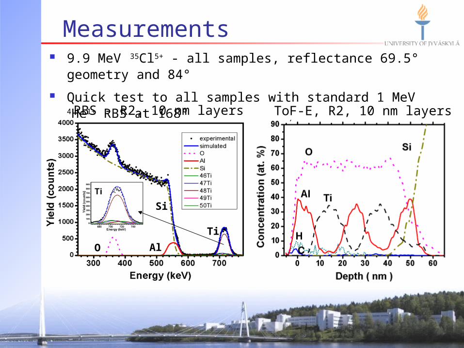
Measurements 9.9 MeV 35Cl5+ - all samples, reflectance 69.5° geometry and 84°
Quick test to all samples with standard 1 MeV 4He1+ RBS at 168°
ToF-E, R2, 10 nm layers
O Al
Si
Ti
RBS - R2, 10 nm layers

Measurements 6.0 MeV 12C3+ - 3 thinnest layered samples, 84° and 86° 0.5 MeV 4He1+ - Rutherford Scattering to forward angles up to 88°
Sample R3, 5 nm layers Sample R4, 2 nm layers

Monte Carlo -simulations MC-simulations made for the spectra in reflectance geometry
Better undertanding of the composition and thicknesses
Sample R2, 10 nm layers, start profile
Difference comes from the incomplete selection of Al counts from Si substrate
(does not effect MC-result)

FURTHER IMPROVEMENTS

Gas ionization detector Thin (~100 nm) SiN
window
Electrons for T2 timing signal emitted from the membrane

Conclusions All Al2O3/TiO2 nanolaminates could be depth profiled and
impurities, including hydrogen were analyzed Nanolaminates with individual layers of 5 nm could be resolved Depth resolution of <2 nm at the surface was reached Gas ionization detector as an energy detector and yet coming
position sensitivity will push the performance to even higher level

Future improvements: Gas ionization detector
TOF-E results from ETH Zürich
Incident ion 12 MeV 127I and borosilicate glass target
Nucl. Instr. and Meth. B 248 (2006) 155-162 200 nm thick SiN membrane from Aalto
University, Finland, on 100 mm wafer
30 mm

ALD 8.6 nm Al2O3/Si Atomic layer deposited Al2O3 film on silicon (Prof. Ritala, U. of Helsinki)
Density of 2.9 g/cm3 and thickness of 8.6 nm determined with XRR (Ritala)
Elemental concentrations in the film bulk as determined with TOF ERDA are O 60±3 at.%, Al 35±2 at.%, H 4±1 at.%. and C 0.5±0.2 at.%

10 nm CNx on silicon TOF-ERDA results from sputter deposited 10 nm thick CNx hard coating on
Si. Measured with 6 MeV 35Cl beam and extreme glancing angle of 3°
A density of 2.0 g/cm3 was used in converting areal densities to nm

Effect of stripper gas pressure
13.6 MeV 63Cu7+ CaPO (hydroxyapatite)

Timing resolution Shape of the MCP signal with the original anode
Risetime ~3 ns for He ions

Electronics and data acquisition Timing gates
Fast Phillips Scientific 776 preamplifier (10×)
Ortec 935 quad CFD
FAST 7072T TDC/ADC, no delay used
Energy detector Implanted 450 mm2 ORTEC detector (ULTRA series)
Ortec 142 preamplifier
Ortec 571 amplifier
FAST 7072T TDC/ADC
Data acquisition with LabVIEW National Instruments FPGA card based multiparameter
data acquisition system, programmed in Jyväskylä
40 MHz (25 ns) time stamping
Can host up to 8 ADCs, easily expandable
List-mode data – coincident events determined off-line!

Depth resolution optimization

TOF-ERDA beamline and chamber
UHV compatible chamber with a load lock
LabVIEW controlled stepping motor driven 6-axis goniometer (Panmure instruments)
Currently sample holder for two samples, holder for 7 samples in design
Beamline equipped with high precision slits and NEC beam profile monitor
Telescope angle 41º

Timing gates: voltages
HV2: –1800 V
10 kΩ
40 MΩ
HV1: –2800 V
10 kΩ
20 MΩ
1 MΩ
99 V
1699 V
MCP stack and ”toblerone”
Carbon foil and outer mirror grid
Cable from anode to SMA leadthrough
ions
e-

Towards position sensitivity Risetime of 1 ns with PCB anode
achieved with the test detector Risetime of 2 ns from lower MCP
electrode through 1 nF capacitor achieved with the test detector
Also ALD-Al2O3 coated carbon foils have been fabricated,much higher electron yields expected

Conclusions New high performance spectrometer has been built in Jyväskylä Detector telescope has high detection efficiency and good
timing resolution Depth resolution of <2 nm at the surface has been reached Position sensitivity and gas ionization detector as an energy
detector will push the performance to even higher level
1st timing detector,
3 μg/cm2 C-foil
2nd timing detector,
10 μg/cm2 C-foil


![COMPLETE PELLETRON SYSTEMS FOR ION BEAM ......National Electrostatics Corp. 7540 Graber Rd., P.O. Box 620310, Middleton, WI 53562-0310 USA 06/14 [IBA] COMPLETE PELLETRON SYSTEMS FOR](https://img.pdfslide.net/doc/110x75/5f218a320471711893037fe6/complete-pelletron-systems-for-ion-beam-national-electrostatics-corp-7540.jpg)