Embed Size (px)
Citation preview
JFE TECHNICAL REPORT No. 24 (Mar. 2019)
Copyright © 2019 JFE Steel Corporation. All Rights Reserved.
142
Development of T-bar Production Technology by Universal RollingTAKASHIMA Yukio*1 YAMAGUCHI Yoichiro*2 TAKAHASHI Hideki*3
Abstract:Application of T-bars in shipbuilding has increased
recently. A new hot section rolling technology by univer-sal rolling was developed to produce slim T-bars suitable for ships. The new process uses universal mills in inter-mediate and finishing rolling. In order to obtain higher productivity, a tandem rolling technology with two uni-versal mills and an edger mill was developed for interme-diate rolling. In the present study, the deformation prop-erties of the tandem rolling was investigated by model rolling experiment. Then T-bar rolling test was carried out at an actual structural mill. As a result, T-bars with target dimensions were successfully produced, and the possibility of the T-bar universal rolling technology was clearly demonstrated.
1. Introduction
Several section steel products are used in ships in order to increase the hull stiffness1). For example, unequal-leg angles and bulb-plates are used in ship-building, and these sections are manufactured by hot rolling with grooved rolls. To achieve higher hull stiff-ness, sections having a height of at least twice their width are generally required for ships, and a wide vari-ety of thicknesses are required for reduction of ship structural weight2).
Application of T-bars in shipbuilding has increased recently. However, it is difficult to produce slim sections suitable for ships by conventional T-bar rolling meth-ods such as groove rolling3,4) and three-roll rolling5,6). As a result, T-bars for ships are typically fabricated by welding two plates. JFE Steel Corporation has carried
out research on new T-bar rolling technologies employ-ing universal mills. Universal rolling technology is widely applied to the manufacture of H-beams7), and universal rolling facilities have been introduced at many structural steel mills. Moreover, because the roll gaps of the horizontal and vertical rolls can be set individu-ally in a universal mill, it is possible to produce prod-ucts with several different thicknesses with the same rolls8).
Our previous studies revealed that rolling of T-bars is possible by determining the appropriate thickness reductions of the web and flange for side camber con-trol. In addition, the influence of rolling conditions on deformation behavior, including flange spread, was investigated9). An extended T-bar rolling technology with a universal mill and an edger mill was investigated by numerical simulation and laboratory rolling experi-ments, and the possibility of manufacturing T-bar products with suitable cross sections for ships with con-ventional universal rolling facilities for H-beam pro-duction was demonstrated10). Furthermore, a new roll-ing method for production of T-bars at an actual structural steel mill was investigated, and mill trials were carried out at the mill11). This paper reports the details of the new production technology, which achieved successful results in T-bar rolling at a com-mercial structural steel mill.
2. Outline of T-Bar Tandem Universal Rolling
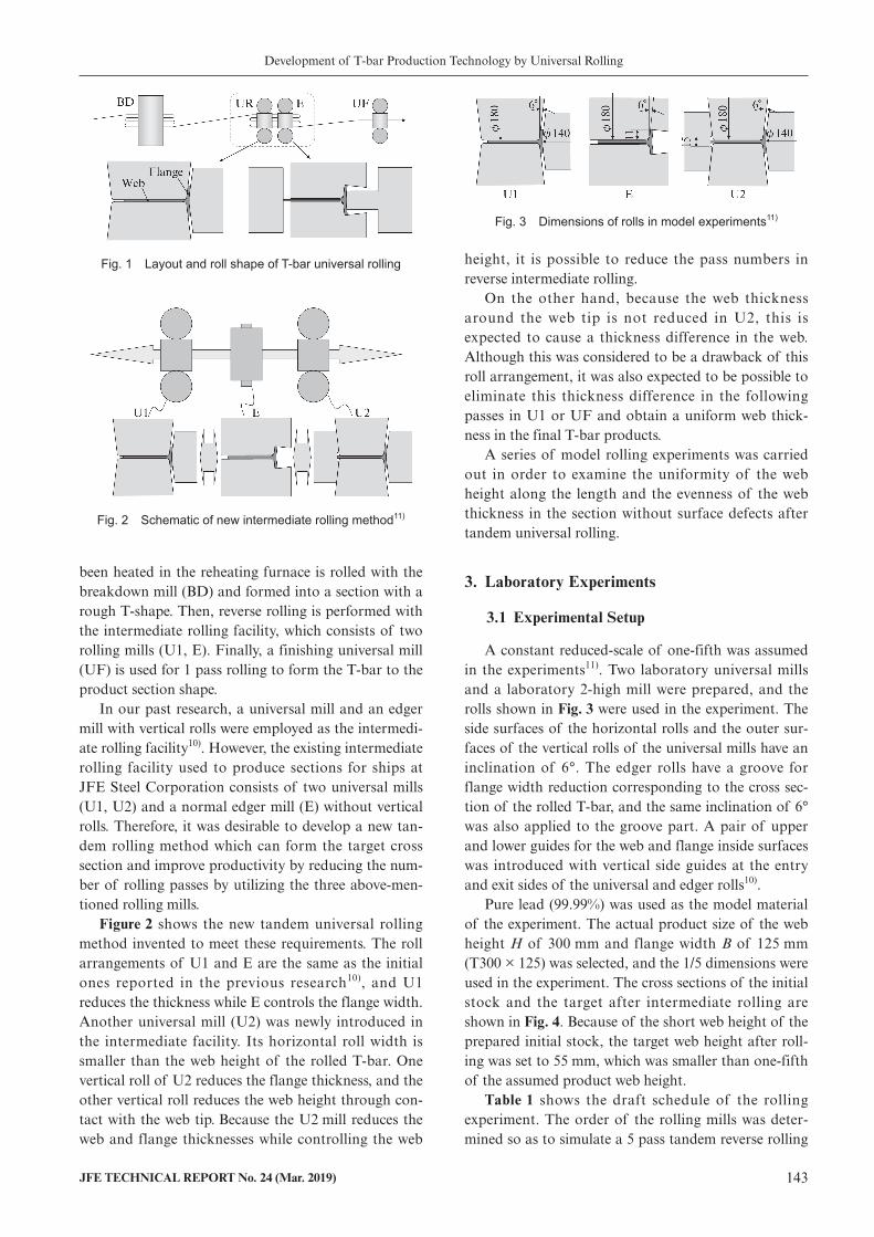
Figure 1 shows the schematic of the universal rolling method developed for manufacturing T-bars for ships. First, in the rough groove rolling step, material that has
† Originally published in JFE GIHO No. 42 (Aug. 2018), p. 90−96 *2 Staff Deputy Manager, Shape Rolling Dept., West Japan Works (Fukuyama), JFE Steel
*1 Dr. Eng., Senior Researcher Deputy General Manager, Rolling & Processing Research Dept., Steel Res. Lab., JFE Steel
*3 Staff General Manager, Planning & Marketing Dept., Construction Materials & Services Business Division, JFE Steel
Development of T-bar Production Technology by Universal Rolling
JFE TECHNICAL REPORT No. 24 (Mar. 2019) 143
been heated in the reheating furnace is rolled with the breakdown mill (BD) and formed into a section with a rough T-shape. Then, reverse rolling is performed with the intermediate rolling facility, which consists of two rolling mills (U1, E). Finally, a finishing universal mill (UF) is used for 1 pass rolling to form the T-bar to the product section shape.
In our past research, a universal mill and an edger mill with vertical rolls were employed as the intermedi-ate rolling facility10). However, the existing intermediate rolling facility used to produce sections for ships at JFE Steel Corporation consists of two universal mills (U1, U2) and a normal edger mill (E) without vertical rolls. Therefore, it was desirable to develop a new tan-dem rolling method which can form the target cross section and improve productivity by reducing the num-ber of rolling passes by utilizing the three above-men-tioned rolling mills.
Figure 2 shows the new tandem universal rolling method invented to meet these requirements. The roll arrangements of U1 and E are the same as the initial ones reported in the previous research10), and U1 reduces the thickness while E controls the flange width. Another universal mill (U2) was newly introduced in the intermediate facility. Its horizontal roll width is smaller than the web height of the rolled T-bar. One vertical roll of U2 reduces the flange thickness, and the other vertical roll reduces the web height through con-tact with the web tip. Because the U2 mill reduces the web and flange thicknesses while controlling the web
height, it is possible to reduce the pass numbers in reverse intermediate rolling.
On the other hand, because the web thickness around the web tip is not reduced in U2, this is expected to cause a thickness difference in the web. Although this was considered to be a drawback of this roll arrangement, it was also expected to be possible to eliminate this thickness difference in the following passes in U1 or UF and obtain a uniform web thick-ness in the final T-bar products.
A series of model rolling experiments was carried out in order to examine the uniformity of the web height along the length and the evenness of the web thickness in the section without surface defects after tandem universal rolling.
3. Laboratory Experiments
3.1 Experimental Setup
A constant reduced-scale of one-fifth was assumed in the experiments11). Two laboratory universal mills and a laboratory 2-high mill were prepared, and the rolls shown in Fig. 3 were used in the experiment. The side surfaces of the horizontal rolls and the outer sur-faces of the vertical rolls of the universal mills have an inclination of 6°. The edger rolls have a groove for flange width reduction corresponding to the cross sec-tion of the rolled T-bar, and the same inclination of 6° was also applied to the groove part. A pair of upper and lower guides for the web and flange inside surfaces was introduced with vertical side guides at the entry and exit sides of the universal and edger rolls10).
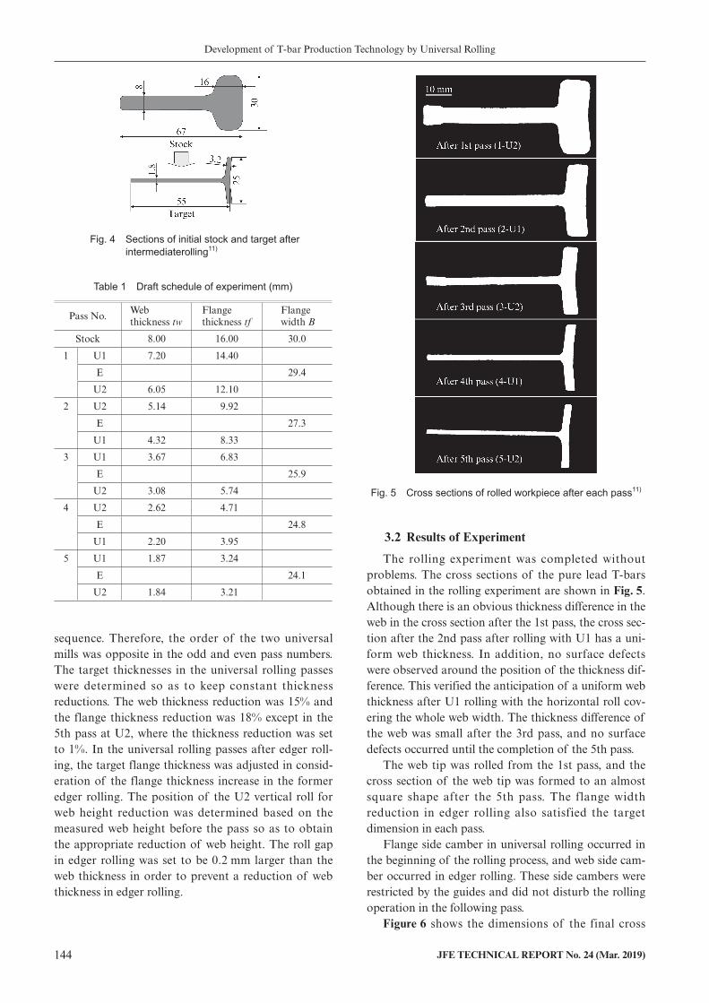
Pure lead (99.99%) was used as the model material of the experiment. The actual product size of the web height H of 300 mm and flange width B of 125 mm (T300 × 125) was selected, and the 1/5 dimensions were used in the experiment. The cross sections of the initial stock and the target after intermediate rolling are shown in Fig. 4. Because of the short web height of the prepared initial stock, the target web height after roll-ing was set to 55 mm, which was smaller than one-fifth of the assumed product web height.
Table 1 shows the draft schedule of the rolling experiment. The order of the rolling mills was deter-mined so as to simulate a 5 pass tandem reverse rolling
Fig. 1 Layout and roll shape of T-bar universal rolling
Fig. 2 Schematic of new intermediate rolling method11)
Fig. 3 Dimensions of rolls in model experiments11)
Development of T-bar Production Technology by Universal Rolling
144 JFE TECHNICAL REPORT No. 24 (Mar. 2019)
sequence. Therefore, the order of the two universal mills was opposite in the odd and even pass numbers. The target thicknesses in the universal rolling passes were determined so as to keep constant thickness reductions. The web thickness reduction was 15% and the flange thickness reduction was 18% except in the 5th pass at U2, where the thickness reduction was set to 1%. In the universal rolling passes after edger roll-ing, the target flange thickness was adjusted in consid-eration of the flange thickness increase in the former edger rolling. The position of the U2 vertical roll for web height reduction was determined based on the measured web height before the pass so as to obtain the appropriate reduction of web height. The roll gap in edger rolling was set to be 0.2 mm larger than the web thickness in order to prevent a reduction of web thickness in edger rolling.
3.2 Results of Experiment
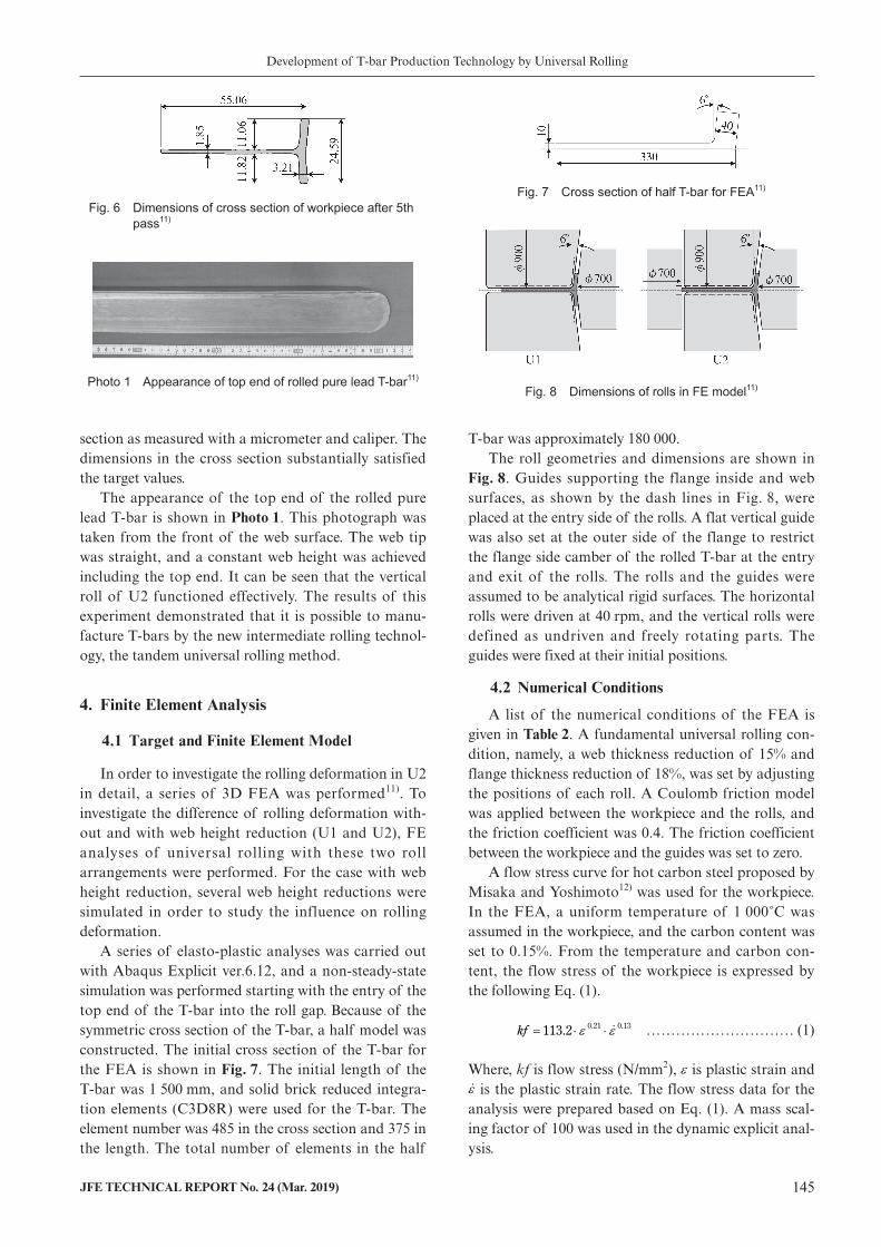
The rolling experiment was completed without problems. The cross sections of the pure lead T-bars obtained in the rolling experiment are shown in Fig. 5. Although there is an obvious thickness difference in the web in the cross section after the 1st pass, the cross sec-tion after the 2nd pass after rolling with U1 has a uni-form web thickness. In addition, no surface defects were observed around the position of the thickness dif-ference. This verified the anticipation of a uniform web thickness after U1 rolling with the horizontal roll cov-ering the whole web width. The thickness difference of the web was small after the 3rd pass, and no surface defects occurred until the completion of the 5th pass.
The web tip was rolled from the 1st pass, and the cross section of the web tip was formed to an almost square shape after the 5th pass. The flange width reduction in edger rolling also satisfied the target dimension in each pass.
Flange side camber in universal rolling occurred in the beginning of the rolling process, and web side cam-ber occurred in edger rolling. These side cambers were restricted by the guides and did not disturb the rolling operation in the following pass.
Figure 6 shows the dimensions of the final cross
Fig. 4 Sections of initial stock and target after intermediaterolling11)
Table 1 Draft schedule of experiment (mm)
Pass No.Web thickness tw
Flange thickness tf
Flange width B
Stock 8.00 16.00 30.0
1 U1 7.20 14.40
E 29.4
U2 6.05 12.10
2 U2 5.14 9.92
E 27.3
U1 4.32 8.33
3 U1 3.67 6.83
E 25.9
U2 3.08 5.74
4 U2 2.62 4.71
E 24.8
U1 2.20 3.95
5 U1 1.87 3.24
E 24.1
U2 1.84 3.21
Fig. 5 Cross sections of rolled workpiece after each pass11)
Development of T-bar Production Technology by Universal Rolling
JFE TECHNICAL REPORT No. 24 (Mar. 2019) 145
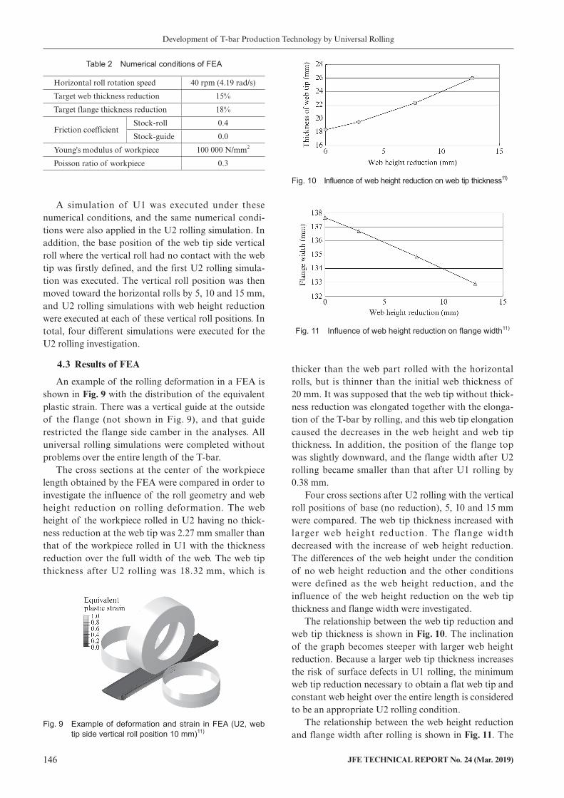
section as measured with a micrometer and caliper. The dimensions in the cross section substantially satisfied the target values.
The appearance of the top end of the rolled pure lead T-bar is shown in Photo 1. This photograph was taken from the front of the web surface. The web tip was straight, and a constant web height was achieved including the top end. It can be seen that the vertical roll of U2 functioned effectively. The results of this experiment demonstrated that it is possible to manu-facture T-bars by the new intermediate rolling technol-ogy, the tandem universal rolling method.
4. Finite Element Analysis
4.1 Target and Finite Element Model
In order to investigate the rolling deformation in U2 in detail, a series of 3D FEA was performed11). To investigate the difference of rolling deformation with-out and with web height reduction (U1 and U2), FE analyses of universal rolling with these two roll arrangements were performed. For the case with web height reduction, several web height reductions were simulated in order to study the influence on rolling deformation.
A series of elasto-plastic analyses was carried out with Abaqus Explicit ver.6.12, and a non-steady-state simulation was performed starting with the entry of the top end of the T-bar into the roll gap. Because of the symmetric cross section of the T-bar, a half model was constructed. The initial cross section of the T-bar for the FEA is shown in Fig. 7. The initial length of the T-bar was 1 500 mm, and solid brick reduced integra-tion elements (C3D8R) were used for the T-bar. The element number was 485 in the cross section and 375 in the length. The total number of elements in the half
T-bar was approximately 180 000.The roll geometries and dimensions are shown in
Fig. 8. Guides supporting the flange inside and web surfaces, as shown by the dash lines in Fig. 8, were placed at the entry side of the rolls. A flat vertical guide was also set at the outer side of the flange to restrict the flange side camber of the rolled T-bar at the entry and exit of the rolls. The rolls and the guides were assumed to be analytical rigid surfaces. The horizontal rolls were driven at 40 rpm, and the vertical rolls were defined as undriven and freely rotating parts. The guides were fixed at their initial positions.
4.2 Numerical Conditions
A list of the numerical conditions of the FEA is given in Table 2. A fundamental universal rolling con-dition, namely, a web thickness reduction of 15% and flange thickness reduction of 18%, was set by adjusting the positions of each roll. A Coulomb friction model was applied between the workpiece and the rolls, and the friction coefficient was 0.4. The friction coefficient between the workpiece and the guides was set to zero.
A flow stress curve for hot carbon steel proposed by Misaka and Yoshimoto12) was used for the workpiece. In the FEA, a uniform temperature of 1 000˚C was assumed in the workpiece, and the carbon content was set to 0.15%. From the temperature and carbon con-tent, the flow stress of the workpiece is expressed by the following Eq. (1).
0.21 0.13113.2kf ………………………… (1)
Where, kf is flow stress (N/mm2), is plastic strain and is the plastic strain rate. The flow stress data for the analysis were prepared based on Eq. (1). A mass scal-ing factor of 100 was used in the dynamic explicit anal-ysis.
Fig. 6 Dimensions of cross section of workpiece after 5th pass11)
Photo 1 Appearance of top end of rolled pure lead T-bar11)
Fig. 7 Cross section of half T-bar for FEA11)
Fig. 8 Dimensions of rolls in FE model11)
Development of T-bar Production Technology by Universal Rolling
146 JFE TECHNICAL REPORT No. 24 (Mar. 2019)
A simulation of U1 was executed under these numerical conditions, and the same numerical condi-tions were also applied in the U2 rolling simulation. In addition, the base position of the web tip side vertical roll where the vertical roll had no contact with the web tip was firstly defined, and the first U2 rolling simula-tion was executed. The vertical roll position was then moved toward the horizontal rolls by 5, 10 and 15 mm, and U2 rolling simulations with web height reduction were executed at each of these vertical roll positions. In total, four different simulations were executed for the U2 rolling investigation.
4.3 Results of FEA
An example of the rolling deformation in a FEA is shown in Fig. 9 with the distribution of the equivalent plastic strain. There was a vertical guide at the outside of the flange (not shown in Fig. 9), and that guide restricted the flange side camber in the analyses. All universal rolling simulations were completed without problems over the entire length of the T-bar.
The cross sections at the center of the workpiece length obtained by the FEA were compared in order to investigate the influence of the roll geometry and web height reduction on rolling deformation. The web height of the workpiece rolled in U2 having no thick-ness reduction at the web tip was 2.27 mm smaller than that of the workpiece rolled in U1 with the thickness reduction over the full width of the web. The web tip thickness after U2 rolling was 18.32 mm, which is
thicker than the web part rolled with the horizontal rolls, but is thinner than the initial web thickness of 20 mm. It was supposed that the web tip without thick-ness reduction was elongated together with the elonga-tion of the T-bar by rolling, and this web tip elongation caused the decreases in the web height and web tip thickness. In addition, the position of the flange top was slightly downward, and the flange width after U2 rolling became smaller than that after U1 rolling by 0.38 mm.
Four cross sections after U2 rolling with the vertical roll positions of base (no reduction), 5, 10 and 15 mm were compared. The web tip thickness increased with larger web height reduction. The flange width decreased with the increase of web height reduction. The differences of the web height under the condition of no web height reduction and the other conditions were defined as the web height reduction, and the influence of the web height reduction on the web tip thickness and flange width were investigated.
The relationship between the web tip reduction and web tip thickness is shown in Fig. 10. The inclination of the graph becomes steeper with larger web height reduction. Because a larger web tip thickness increases the risk of surface defects in U1 rolling, the minimum web tip reduction necessary to obtain a flat web tip and constant web height over the entire length is considered to be an appropriate U2 rolling condition.
The relationship between the web height reduction and flange width after rolling is shown in Fig. 11. The
Table 2 Numerical conditions of FEA
Horizontal roll rotation speed 40 rpm (4.19 rad/s)
Target web thickness reduction 15%
Target flange thickness reduction 18%
Friction coefficientStock-roll 0.4
Stock-guide 0.0
Young's modulus of workpiece 100 000 N/mm2
Poisson ratio of workpiece 0.3
Fig. 9 Example of deformation and strain in FEA (U2, web tip side vertical roll position 10 mm)11)
Fig. 10 Influence of web height reduction on web tip thickness11)
Fig. 11 Influence of web height reduction on flange width11)
Development of T-bar Production Technology by Universal Rolling
JFE TECHNICAL REPORT No. 24 (Mar. 2019) 147
flange width after U2 rolling decreased linearly against the web height reduction. Due to the web height reduc-tion, the deformation in the length direction around the web tip increased, and the web elongation became larger. In turn, the larger web elongation increased flange elongation, and flange spread decreased. If the decrease of flange width becomes excessive, an insuffi-cient product flange width is possible. Therefore, it was also concluded that an excessively large web height reduction should be avoided in U2 rolling.
5. Mill Trial of T-Bar Tandem Universal Rolling
5.1 Mill Trial Facilities and Rolling Conditions
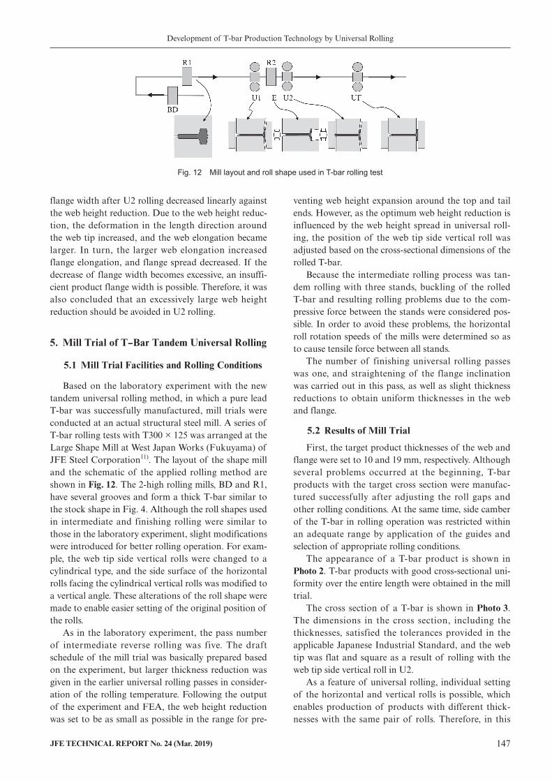
Based on the laboratory experiment with the new tandem universal rolling method, in which a pure lead T-bar was successfully manufactured, mill trials were conducted at an actual structural steel mill. A series of T-bar rolling tests with T300 × 125 was arranged at the Large Shape Mill at West Japan Works (Fukuyama) of JFE Steel Corporation11). The layout of the shape mill and the schematic of the applied rolling method are shown in Fig. 12. The 2-high rolling mills, BD and R1, have several grooves and form a thick T-bar similar to the stock shape in Fig. 4. Although the roll shapes used in intermediate and finishing rolling were similar to those in the laboratory experiment, slight modifications were introduced for better rolling operation. For exam-ple, the web tip side vertical rolls were changed to a cylindrical type, and the side surface of the horizontal rolls facing the cylindrical vertical rolls was modified to a vertical angle. These alterations of the roll shape were made to enable easier setting of the original position of the rolls.
As in the laboratory experiment, the pass number of intermediate reverse rolling was five. The draft schedule of the mill trial was basically prepared based on the experiment, but larger thickness reduction was given in the earlier universal rolling passes in consider-ation of the rolling temperature. Following the output of the experiment and FEA, the web height reduction was set to be as small as possible in the range for pre-
venting web height expansion around the top and tail ends. However, as the optimum web height reduction is influenced by the web height spread in universal roll-ing, the position of the web tip side vertical roll was adjusted based on the cross-sectional dimensions of the rolled T-bar.
Because the intermediate rolling process was tan-dem rolling with three stands, buckling of the rolled T-bar and resulting rolling problems due to the com-pressive force between the stands were considered pos-sible. In order to avoid these problems, the horizontal roll rotation speeds of the mills were determined so as to cause tensile force between all stands.
The number of finishing universal rolling passes was one, and straightening of the flange inclination was carried out in this pass, as well as slight thickness reductions to obtain uniform thicknesses in the web and flange.
5.2 Results of Mill Trial
First, the target product thicknesses of the web and flange were set to 10 and 19 mm, respectively. Although several problems occurred at the beginning, T-bar products with the target cross section were manufac-tured successfully after adjusting the roll gaps and other rolling conditions. At the same time, side camber of the T-bar in rolling operation was restricted within an adequate range by application of the guides and selection of appropriate rolling conditions.
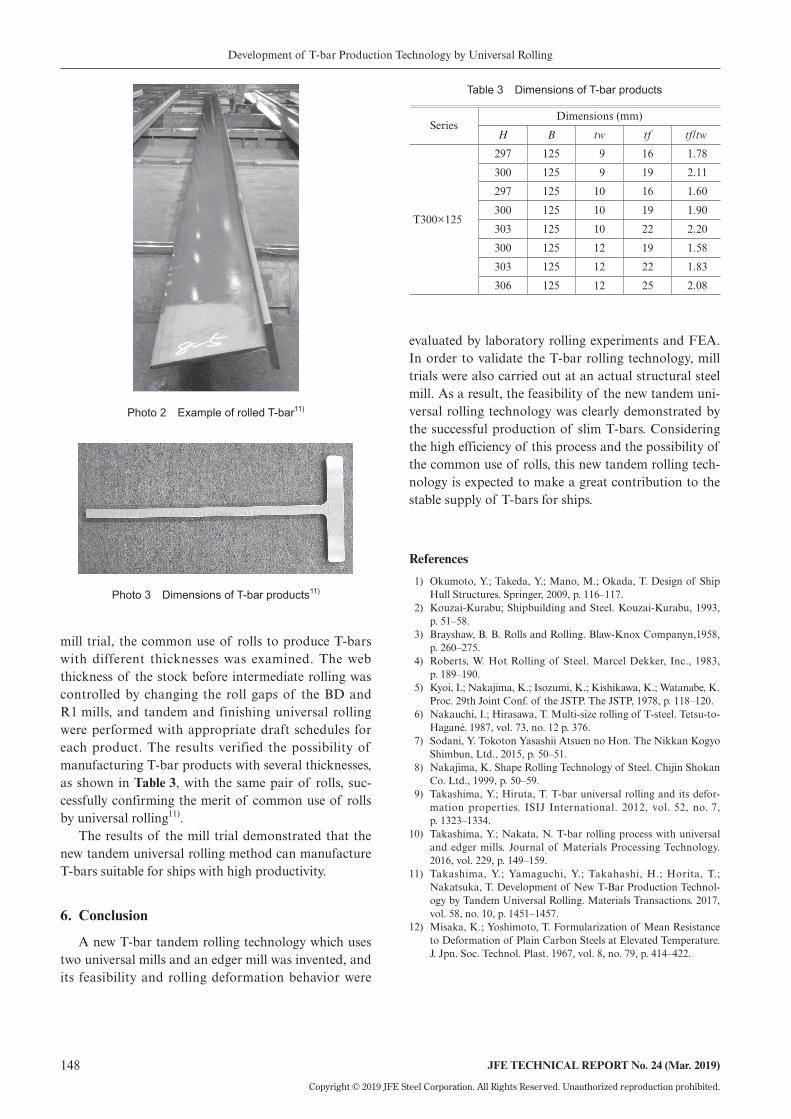
The appearance of a T-bar product is shown in Photo 2. T-bar products with good cross-sectional uni-formity over the entire length were obtained in the mill trial.
The cross section of a T-bar is shown in Photo 3. The dimensions in the cross section, including the thicknesses, satisfied the tolerances provided in the applicable Japanese Industrial Standard, and the web tip was flat and square as a result of rolling with the web tip side vertical roll in U2.
As a feature of universal rolling, individual setting of the horizontal and vertical rolls is possible, which enables production of products with different thick-nesses with the same pair of rolls. Therefore, in this
Fig. 12 Mill layout and roll shape used in T-bar rolling test
Development of T-bar Production Technology by Universal Rolling
148 JFE TECHNICAL REPORT No. 24 (Mar. 2019)
Copyright © 2019 JFE Steel Corporation. All Rights Reserved. Unauthorized reproduction prohibited.
mill trial, the common use of rolls to produce T-bars with different thicknesses was examined. The web thickness of the stock before intermediate rolling was controlled by changing the roll gaps of the BD and R1 mills, and tandem and finishing universal rolling were performed with appropriate draft schedules for each product. The results verified the possibility of manufacturing T-bar products with several thicknesses, as shown in Table 3, with the same pair of rolls, suc-cessfully confirming the merit of common use of rolls by universal rolling11).
The results of the mill trial demonstrated that the new tandem universal rolling method can manufacture T-bars suitable for ships with high productivity.
6. Conclusion
A new T-bar tandem rolling technology which uses two universal mills and an edger mill was invented, and its feasibility and rolling deformation behavior were
evaluated by laboratory rolling experiments and FEA. In order to validate the T-bar rolling technology, mill trials were also carried out at an actual structural steel mill. As a result, the feasibility of the new tandem uni-versal rolling technology was clearly demonstrated by the successful production of slim T-bars. Considering the high efficiency of this process and the possibility of the common use of rolls, this new tandem rolling tech-nology is expected to make a great contribution to the stable supply of T-bars for ships.
References
1) Okumoto, Y.; Takeda, Y.; Mano, M.; Okada, T. Design of Ship Hull Structures. Springer, 2009, p. 116–117.
2) Kouzai-Kurabu; Shipbuilding and Steel. Kouzai-Kurabu, 1993, p. 51–58.
3) Brayshaw, B. B. Rolls and Rolling. Blaw-Knox Companyn,1958, p. 260–275.
4) Roberts, W. Hot Rolling of Steel. Marcel Dekker, Inc., 1983, p. 189–190.
5) Kyoi, I.; Nakajima, K.; Isozumi, K.; Kishikawa, K.; Watanabe, K. Proc. 29th Joint Conf. of the JSTP. The JSTP, 1978, p. 118–120.
6) Nakauchi, I.; Hirasawa, T. Multi-size rolling of T-steel. Tetsu-to-Hagané. 1987, vol. 73, no. 12 p. 376.
7) Sodani, Y. Tokoton Yasashii Atsuen no Hon. The Nikkan Kogyo Shimbun, Ltd., 2015, p. 50–51.
8) Nakajima, K. Shape Rolling Technology of Steel. Chijin Shokan Co. Ltd., 1999, p. 50–59.
9) Takashima, Y.; Hiruta, T. T-bar universal rolling and its defor-mation properties. ISIJ International. 2012, vol. 52, no. 7, p. 1323–1334.
10) Takashima, Y.; Nakata, N. T-bar rolling process with universal and edger mills. Journal of Materials Processing Technology. 2016, vol. 229, p. 149–159.
11) Takashima, Y.; Yamaguchi, Y.; Takahashi, H.; Horita, T.; Nakatsuka, T. Development of New T-Bar Production Technol-ogy by Tandem Universal Rolling. Materials Transactions. 2017, vol. 58, no. 10, p. 1451–1457.
12) Misaka, K.; Yoshimoto, T. Formularization of Mean Resistance to Deformation of Plain Carbon Steels at Elevated Temperature. J. Jpn. Soc. Technol. Plast. 1967, vol. 8, no. 79, p. 414–422.
Photo 2 Example of rolled T-bar11)
Photo 3 Dimensions of T-bar products11)
Table 3 Dimensions of T-bar products
SeriesDimensions (mm)
H B tw tf tf/tw
T300×125
297 125 9 16 1.78
300 125 9 19 2.11
297 125 10 16 1.60
300 125 10 19 1.90
303 125 10 22 2.20
300 125 12 19 1.58
303 125 12 22 1.83
306 125 12 25 2.08